EP4477885A2 - Fluidmaschine und betriebsverfahren dafür - Google Patents
Fluidmaschine und betriebsverfahren dafür Download PDFInfo
- Publication number
- EP4477885A2 EP4477885A2 EP24175460.5A EP24175460A EP4477885A2 EP 4477885 A2 EP4477885 A2 EP 4477885A2 EP 24175460 A EP24175460 A EP 24175460A EP 4477885 A2 EP4477885 A2 EP 4477885A2
- Authority
- EP
- European Patent Office
- Prior art keywords
- slide valve
- pressure
- screws
- pressure chamber
- discharge end
- Prior art date
- Legal status (The legal status is an assumption and is not a legal conclusion. Google has not performed a legal analysis and makes no representation as to the accuracy of the status listed.)
- Pending
Links
Images






Classifications
-
- F—MECHANICAL ENGINEERING; LIGHTING; HEATING; WEAPONS; BLASTING
- F04—POSITIVE - DISPLACEMENT MACHINES FOR LIQUIDS; PUMPS FOR LIQUIDS OR ELASTIC FLUIDS
- F04C—ROTARY-PISTON, OR OSCILLATING-PISTON, POSITIVE-DISPLACEMENT MACHINES FOR LIQUIDS; ROTARY-PISTON, OR OSCILLATING-PISTON, POSITIVE-DISPLACEMENT PUMPS
- F04C18/00—Rotary-piston pumps specially adapted for elastic fluids
- F04C18/08—Rotary-piston pumps specially adapted for elastic fluids of intermeshing-engagement type, i.e. with engagement of co-operating members similar to that of toothed gearing
- F04C18/12—Rotary-piston pumps specially adapted for elastic fluids of intermeshing-engagement type, i.e. with engagement of co-operating members similar to that of toothed gearing of other than internal-axis type
- F04C18/14—Rotary-piston pumps specially adapted for elastic fluids of intermeshing-engagement type, i.e. with engagement of co-operating members similar to that of toothed gearing of other than internal-axis type with toothed rotary pistons
- F04C18/16—Rotary-piston pumps specially adapted for elastic fluids of intermeshing-engagement type, i.e. with engagement of co-operating members similar to that of toothed gearing of other than internal-axis type with toothed rotary pistons with helical teeth, e.g. chevron-shaped, screw type
-
- F—MECHANICAL ENGINEERING; LIGHTING; HEATING; WEAPONS; BLASTING
- F04—POSITIVE - DISPLACEMENT MACHINES FOR LIQUIDS; PUMPS FOR LIQUIDS OR ELASTIC FLUIDS
- F04C—ROTARY-PISTON, OR OSCILLATING-PISTON, POSITIVE-DISPLACEMENT MACHINES FOR LIQUIDS; ROTARY-PISTON, OR OSCILLATING-PISTON, POSITIVE-DISPLACEMENT PUMPS
- F04C23/00—Combinations of two or more pumps, each being of rotary-piston or oscillating-piston type, specially adapted for elastic fluids; Pumping installations specially adapted for elastic fluids; Multi-stage pumps specially adapted for elastic fluids
- F04C23/001—Combinations of two or more pumps, each being of rotary-piston or oscillating-piston type, specially adapted for elastic fluids; Pumping installations specially adapted for elastic fluids; Multi-stage pumps specially adapted for elastic fluids of similar working principle
-
- F—MECHANICAL ENGINEERING; LIGHTING; HEATING; WEAPONS; BLASTING
- F04—POSITIVE - DISPLACEMENT MACHINES FOR LIQUIDS; PUMPS FOR LIQUIDS OR ELASTIC FLUIDS
- F04C—ROTARY-PISTON, OR OSCILLATING-PISTON, POSITIVE-DISPLACEMENT MACHINES FOR LIQUIDS; ROTARY-PISTON, OR OSCILLATING-PISTON, POSITIVE-DISPLACEMENT PUMPS
- F04C23/00—Combinations of two or more pumps, each being of rotary-piston or oscillating-piston type, specially adapted for elastic fluids; Pumping installations specially adapted for elastic fluids; Multi-stage pumps specially adapted for elastic fluids
- F04C23/001—Combinations of two or more pumps, each being of rotary-piston or oscillating-piston type, specially adapted for elastic fluids; Pumping installations specially adapted for elastic fluids; Multi-stage pumps specially adapted for elastic fluids of similar working principle
- F04C23/003—Combinations of two or more pumps, each being of rotary-piston or oscillating-piston type, specially adapted for elastic fluids; Pumping installations specially adapted for elastic fluids; Multi-stage pumps specially adapted for elastic fluids of similar working principle having complementary function
-
- F—MECHANICAL ENGINEERING; LIGHTING; HEATING; WEAPONS; BLASTING
- F04—POSITIVE - DISPLACEMENT MACHINES FOR LIQUIDS; PUMPS FOR LIQUIDS OR ELASTIC FLUIDS
- F04C—ROTARY-PISTON, OR OSCILLATING-PISTON, POSITIVE-DISPLACEMENT MACHINES FOR LIQUIDS; ROTARY-PISTON, OR OSCILLATING-PISTON, POSITIVE-DISPLACEMENT PUMPS
- F04C23/00—Combinations of two or more pumps, each being of rotary-piston or oscillating-piston type, specially adapted for elastic fluids; Pumping installations specially adapted for elastic fluids; Multi-stage pumps specially adapted for elastic fluids
- F04C23/02—Pumps characterised by combination with, or adaptation to, specific driving engines or motors
-
- F—MECHANICAL ENGINEERING; LIGHTING; HEATING; WEAPONS; BLASTING
- F04—POSITIVE - DISPLACEMENT MACHINES FOR LIQUIDS; PUMPS FOR LIQUIDS OR ELASTIC FLUIDS
- F04C—ROTARY-PISTON, OR OSCILLATING-PISTON, POSITIVE-DISPLACEMENT MACHINES FOR LIQUIDS; ROTARY-PISTON, OR OSCILLATING-PISTON, POSITIVE-DISPLACEMENT PUMPS
- F04C28/00—Control of, monitoring of, or safety arrangements for, pumps or pumping installations specially adapted for elastic fluids
- F04C28/18—Control of, monitoring of, or safety arrangements for, pumps or pumping installations specially adapted for elastic fluids characterised by varying the volume of the working chamber
- F04C28/185—Control of, monitoring of, or safety arrangements for, pumps or pumping installations specially adapted for elastic fluids characterised by varying the volume of the working chamber by varying the useful pumping length of the cooperating members in the axial direction
-
- F—MECHANICAL ENGINEERING; LIGHTING; HEATING; WEAPONS; BLASTING
- F04—POSITIVE - DISPLACEMENT MACHINES FOR LIQUIDS; PUMPS FOR LIQUIDS OR ELASTIC FLUIDS
- F04C—ROTARY-PISTON, OR OSCILLATING-PISTON, POSITIVE-DISPLACEMENT MACHINES FOR LIQUIDS; ROTARY-PISTON, OR OSCILLATING-PISTON, POSITIVE-DISPLACEMENT PUMPS
- F04C29/00—Component parts, details or accessories of pumps or pumping installations, not provided for in groups F04C18/00 - F04C28/00
-
- F—MECHANICAL ENGINEERING; LIGHTING; HEATING; WEAPONS; BLASTING
- F04—POSITIVE - DISPLACEMENT MACHINES FOR LIQUIDS; PUMPS FOR LIQUIDS OR ELASTIC FLUIDS
- F04C—ROTARY-PISTON, OR OSCILLATING-PISTON, POSITIVE-DISPLACEMENT MACHINES FOR LIQUIDS; ROTARY-PISTON, OR OSCILLATING-PISTON, POSITIVE-DISPLACEMENT PUMPS
- F04C29/00—Component parts, details or accessories of pumps or pumping installations, not provided for in groups F04C18/00 - F04C28/00
- F04C29/12—Arrangements for admission or discharge of the working fluid, e.g. constructional features of the inlet or outlet
-
- F—MECHANICAL ENGINEERING; LIGHTING; HEATING; WEAPONS; BLASTING
- F04—POSITIVE - DISPLACEMENT MACHINES FOR LIQUIDS; PUMPS FOR LIQUIDS OR ELASTIC FLUIDS
- F04C—ROTARY-PISTON, OR OSCILLATING-PISTON, POSITIVE-DISPLACEMENT MACHINES FOR LIQUIDS; ROTARY-PISTON, OR OSCILLATING-PISTON, POSITIVE-DISPLACEMENT PUMPS
- F04C29/00—Component parts, details or accessories of pumps or pumping installations, not provided for in groups F04C18/00 - F04C28/00
- F04C29/12—Arrangements for admission or discharge of the working fluid, e.g. constructional features of the inlet or outlet
- F04C29/124—Arrangements for admission or discharge of the working fluid, e.g. constructional features of the inlet or outlet with inlet and outlet valves specially adapted for rotary or oscillating piston pumps
-
- F—MECHANICAL ENGINEERING; LIGHTING; HEATING; WEAPONS; BLASTING
- F04—POSITIVE - DISPLACEMENT MACHINES FOR LIQUIDS; PUMPS FOR LIQUIDS OR ELASTIC FLUIDS
- F04C—ROTARY-PISTON, OR OSCILLATING-PISTON, POSITIVE-DISPLACEMENT MACHINES FOR LIQUIDS; ROTARY-PISTON, OR OSCILLATING-PISTON, POSITIVE-DISPLACEMENT PUMPS
- F04C2240/00—Components
- F04C2240/80—Other components
- F04C2240/81—Sensor, e.g. electronic sensor for control or monitoring
Definitions
- the present disclosure relates to a fluid machine such as a compressor or expander and, more particularly, to a fluid machine and an operating method thereof.
- Existing common two-stage helical machines internally have a sequentially connected low-pressure chamber, an intermediate-pressure chamber, and a high-pressure chamber.
- the low-pressure chamber houses a first-stage rotor
- the high-pressure chamber houses a second-stage rotor
- the intermediate-pressure chamber accommodates a motor and a rotary shaft that connects the first-stage rotor and the second-stage rotor.
- Fluids (such as refrigerants, coolants, etc.) are compressed by the first-stage and second-stage rotors in succession, causing the fluid pressure in the low-pressure chamber, intermediate-pressure chamber, and high-pressure chamber to be at low, intermediate, and high pressures, respectively.
- the intermediate pressure in the intermediate-pressure chamber of the conventional two-stage helical machine cannot be adjusted and can only passively conform to changes in system pressure, preventing the two-stage helical machine from achieving optimal efficiency.
- the suction pressure is too high, it may cause the pressure (intermediate pressure) in the intermediate-pressure chamber to be too high, which may prevent the injection of a lubricating fluid into the intermediate-pressure and high-pressure chambers. This results in insufficient oil supply pressure difference for the second-stage rotor, thereby reducing the efficiency of the two-stage helical machine.
- the present disclosure provides a fluid machine and an operating method thereof. Based on a rotational speed of co-axially rotating first and second screws and interior pressure values of an intermediate-pressure chamber, a controller adjusts relative positions of a first slide valve to the first screws and a second slide valve to the second screws. This adjustment modifies the interior pressure of the intermediate-pressure chamber to prevent excessive pressure, ensuring that a lubricating fluid is steadily injected into the intermediate chamber and a high-pressure chamber. The lubricating fluid continuously lubricates the second screws, enhancing the operational efficiency of the fluid machine.
- a fluid machine including: a main body internally divided into a low-pressure chamber, an intermediate-pressure chamber, and a high-pressure chamber, sequentially interconnected to each other; a screw set, including a pair of first screws accommodated in the low-pressure chamber and engaged with each other, and a pair of second screws accommodated in the high-pressure chamber and engaged with each other, wherein a first contact line is defined between the pair of first screws, and a second contact line is defined between the pair of second screws; a drive module disposed in the intermediate-pressure chamber, wherein the drive module is connected to and drives one of the first screws and one of the second screws to rotate coaxially; a capacity adjustment mechanism, including a first slide valve movably disposed corresponding to the first contact line and a second slide valve movably disposed corresponding to the second contact line; an intermediate pressure sensor disposed in the intermediate-pressure chamber, wherein the intermediate pressure sensor obtains an interior pressure of the intermediate-pressure chamber; and a controller connected to and driving movement of
- an operating method of a fluid machine including following steps: step A, providing the fluid machine of claim 2, positioning the first slide valve between the intermediate-pressure chamber and the first discharge end, and positioning the second slide valve between the exhaust port and the second discharge end, wherein the drive module drives one of the first screws and one of the second screws to rotate at a preset rotational speed with a fixed frequency; step B, the controller controlling the second slide valve to move from between the exhaust port and the second discharge end towards the second suction end; and step C, the controller controlling the first slide valve to move from between the intermediate-pressure chamber and the first discharge end towards the first suction end, until the intermediate pressure sensor detects that the interior pressure of the intermediate-pressure chamber is equal to a preset intermediate pressure.
- an operating method of a fluid machine including following steps: step F, providing the fluid machine of claim 2, positioning the first slide valve between the intermediate-pressure chamber and the first discharge end, and positioning the second slide valve between the exhaust port and the second discharge end, wherein the drive module drives one of the first screws and one of the second screws to rotate at a preset rotational speed with a fixed frequency; step G, the controller controlling the first slide valve to move from the first discharge end towards the first suction end until the first slide valve covers the first suction end, and the second slide valve to move from the second discharge end towards the second suction end such that one end of the second slide valve is positioned between the second suction end and the second discharge end, and another end of the second slide valve is positioned between the exhaust port and the second discharge end; and step H, the controller first controlling the first radial notch to be positioned at a designated position between the first suction end and the first discharge end, then controlling the second slide valve to move towards either the second suction end or the second discharge end,
- an operating method of a fluid machine including following steps: step K, providing the fluid machine of claim 2, positioning the first radial notch between the first suction end and a midpoint of the pair of first screws, the drive module driving one of the first screws and one of the second screws to accelerate to rotate at a low rotational speed; step L, the controller controlling the second slide valve to move from the second discharge end towards the second suction end, such that one end of the second slide valve is positioned between the second suction end and the second discharge end, and another end of the second slide valve is positioned between the exhaust port and the second discharge end, the drive module then continuing to accelerate one of the first screws and one of the second screws to a preset rotational speed for constant-speed rotation; and step M, the controller first positioning the first radial notch at a designated position between the first suction end and the first discharge end, then controlling the second slide valve to move towards either the second suction end or the second discharge end, until the intermediate pressure sensor detects that the interior pressure of the intermediate
- the controller adjusts the positions of the first slide valve and the second slide valve relative to the pair of first screws and the pair of second screws, respectively, based on the rotational speeds of the first and second screws and the interior pressure values of the intermediate-pressure chamber.
- This adjustment regulates the interior pressure of the intermediate-pressure chamber to maintain the interior pressure at a preset intermediate pressure, ensuring that the lubricating fluid is steadily injected into the intermediate-pressure chamber and the high-pressure chamber.
- the lubricating fluid Once the lubricating fluid enters the intermediate-pressure chamber and the high-pressure chamber, the lubricating fluid continues to lubricate the second screw with the fluid flow, achieving good operational efficiency for the fluid machine of this disclosure.
- the present disclosure provides a fluid machine and an operating method.
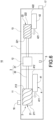
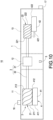
- the fluid machine 10 mainly includes a main body 1, a screw set 2, a drive module 3, a capacity adjustment mechanism 4, an intermediate pressure sensor 5, and a controller 6.
- an interior of the main body 1 is divided into a low-pressure chamber 11, an intermediate-pressure chamber 12, and a high-pressure chamber 13, which are sequentially interconnected.
- the main body 1 includes a first auxiliary chamber 14 arranged on one side of the low-pressure chamber 11 and communicating with low-pressure chamber 11, and a second auxiliary chamber 15 arranged on one side of the high-pressure chamber 13 and communicating with the high-pressure chamber 13.
- the low-pressure chamber 11 has an intake port 16, and the high-pressure chamber 13 has an exhaust port 17.
- the intermediate-pressure chamber 12 and the high-pressure chamber 13 communicate with an oil reservoir (not illustrated), which is used to inject a lubricating fluid into the intermediate-pressure chamber 12 and the high-pressure chamber 13.
- the screw set 2 includes a pair of first screws 21 housed in the low-pressure chamber 11 and meshing with each other, and a pair of second screws 22 housed in the high-pressure chamber 13 and meshing with each other.
- a first contact line Z1 is defined between meshing male and female helical tooth surfaces of the pair of first screws 21, and a second contact line Z2 is defined between meshing male and female helical tooth surfaces of the pair of second screws 22.
- first screws 21 is provided with a first suction end 211 and a first discharge end 212 at two ends
- second screws 22 is provided with a second suction end 221 and a second discharge end 222 at two ends.
- a fluid (such as refrigerant, coolant, etc.) starts from the intake port 16 and sequentially passes through the low-pressure chamber 11, the first suction ends 211 of the first screws 21, the first discharge ends 212 of the first screws 21, the intermediate-pressure chamber 12, the high-pressure chamber 13, the second suction ends 221 of the second screws 22, and the second discharge ends 222 of the second screws 22, and is finally expelled from the exhaust port 17. Because the fluid is successively compressed by the first screws 21 and the second screws 22, the fluid pressure in the low-pressure chamber 11, the intermediate-pressure chamber 12, and the high-pressure chamber 13 is respectively at low, intermediate, and high pressures.
- the fluid machine 10 of this disclosure further includes an evaporator (not illustrated) and a temperature sensor (not illustrated) installed on the evaporator.
- the fluid flows through the low-pressure chamber 11, the intermediate-pressure chamber 12, the high-pressure chamber 13, and the evaporator (not illustrated).
- the temperature sensor or a pressure sensor (not illustrated) is used to detect and obtain the temperature and pressure of the evaporator.
- the aforementioned temperature could be a target temperature set for the evaporator or an actual temperature of the environment that the evaporator has created.
- the controller may use the measured temperature and pressure to calculate a saturation temperature of the refrigerant, thereby controlling the capacity adjustment mechanism 4.
- the drive module 3 is accommodated within the intermediate-pressure chamber 12 and includes a motor 31 and one or two drive shafts 32 that connect to the motor 31, the pair of first screws 21, and the pair of second screws 22.
- the motor 31 drives one of the first screws 21 and one of the second screws 22 to rotate coaxially via the drive shaft 32.
- this configuration is not limiting; there may be two drive shafts, with rotational axes of both the drive shafts 32 aligned on the same line.
- one drive shaft 32 connects to the motor 31 and one of the first screws 21, and the other drive shaft 32 connects to the motor 31 and one of the second screws 22.
- This setup independently drives both one of the first screws 21 and one of the second screws 22 to rotate coaxially.
- the capacity adjustment mechanism 4 includes a first slide valve 41, which is movably disposed corresponding to the first contact line Z1, and a second slide valve 42, which is movably set corresponding to the second contact line Z2.
- the first slide valve 41 is accommodated and slides within the first auxiliary chamber 14, while the second slide valve 42 is accommodated and slides within the second auxiliary chamber 15.
- One end of the first slide valve 41 is provided with a first low-pressure end 411 arranged corresponding to the first suction end 211, and the other end of the first slide valve 41 is provided with a first radial notch 412 arranged corresponding to the first contact line Z1.
- the first radial notch 412 may be arranged corresponding to any groove location within spiral grooves of the pair of first screws 21, thereby enabling control over when the low-pressure chamber 11 begins to exhaust and an exhaust pressure at which this exhaust happens. The closer a position of the first radial notch 412 is to the first discharge end 212, the greater the exhaust pressure.
- one end of the second slide valve 42 is provided with a second low-pressure end 421 arranged corresponding to the second suction end 221, and the other end of the second slide valve 42 is provided with a second radial notch 422 arranged corresponding to the second contact line Z2.
- the second radial notch 422 may be positioned corresponding to any groove location within spiral grooves of the pair of the second screws 22, thereby controlling when the high-pressure chamber 13 begins to exhaust and an exhaust pressure at which this exhaust happens. The closer a position of the second radial notch 422 is to the second discharge end 222, the greater the exhaust pressure.
- the intermediate pressure sensor 5 is accommodated within the intermediate-pressure chamber 12.
- the intermediate pressure sensor 5 is used to sense and obtain an internal pressure of the intermediate-pressure chamber 12, that is, to measure an interior pressure of the intermediate-pressure chamber 12 and generate an intermediate-pressure chamber pressure signal.
- a pressure sensor (not illustrated) is also installed inside the intake port 16, which is used to sense and obtain a pressure at the intake port 16.
- the controller 6 is connected to and drives the movement of the first slide valve 41 and the second slide valve 42. Based on a rotational speed at which one of the first screws 21 and one of the second screws 22 co-axially rotate, as well as the values of the interior pressure, the controller 6 thus moves the first slide valve 41 relative to the pair of first screws 21, and moves the second slide valve 42 relative to the pair of second screws 22. That is, upon receiving the pressure signals from the intermediate-pressure chamber and the intake port 16, the controller 6 judges and calculates to adjust the relative positions of the first slide valve 41 and the second slide valve 42.
- FIG. 4 illustrates a first step in an operating method of the fluid machine 10 of the present disclosure, further explained as follows.
- a fluid machine 10 as previously described is provided.
- the first slide valve 41 is disposed between the intermediate-pressure chamber 12 and the first discharge end 212
- the second slide valve 42 is disposed between the exhaust port 17 and the second discharge end 222.
- the drive module 3 drives one of the first screws 21 and one of the second screws 22 to rotate at a constant preset rotational speed, which is between 2950 to 3600 rpm, meaning a rotational frequency of the pair of first screws 21 and the pair of second screws 22 is fixed.
- the lubricating fluid starts to be injected into the intermediate-pressure chamber 12 and the high-pressure chamber 13.
- the controller 6 controls the second slide valve 42 to move from between the exhaust port 17 and the second discharge end 222 towards the second suction end 221, thereby increasing a suction volume of the pair of second screws 22.
- the controller 6 controls the first slide valve 41 to move from between the intermediate-pressure chamber 12 and the first discharge end 212 towards the first suction end 211, thereby increasing a suction volume of the pair of first screws 21, until the intermediate pressure sensor 5 detects that the interior pressure of the intermediate-pressure chamber 12 is equal to a preset intermediate pressure.
- the position of the first slide valve 41 is determined by the controller 6 through calculations using the signals of the refrigerant saturation temperature of the evaporator and the interior pressure of the intermediate-pressure chamber 12.
- step D of FIG. 4 and in FIG. 7 when the first slide valve 41 moves to cover the first suction end 211, and a length of the second slide valve 42 between the second suction end 221 and the second discharge end 222 is equal to or less than 80% of a total length of the second slide valve 42, and the interior pressure of the intermediate-pressure chamber 12 is still not equal to the preset intermediate pressure, the controller 6 first controls the position of the first radial notch 412 to be at a designated position between the first suction end 211 and the first discharge end 212.
- the controller 6 controls the second slide valve 42 to move towards the second suction end 221 (to increase the suction volume of the pair of second screws 22) or towards the second discharge end 222 (to decrease the suction volume of the pair of second screws 22), until the intermediate pressure sensor 5 detects that the interior pressure of the intermediate-pressure chamber 12 is equal to the preset intermediate pressure.
- the designated position is determined by the controller 6 through calculations from the signals of the pressure at the intake port 16, the refrigerant saturation temperature at the evaporator, and the interior pressure of the intermediate-pressure chamber 12.
- step D is a special case and may not always occur. It may be omitted depending on the actual operating method of the fluid machine 10 of the present disclosure.
- step E of FIG. 4 and in FIG. 5 the controller 6 first moves the first slide valve 41 towards the first discharge end 212 and the second slide valve 42 towards the second suction end 221. Then, the drive module 3 is shut down. After the first screw 21 and the second screw 22 stop rotating, the lubricating fluid stops being injected into the intermediate-pressure chamber 12 and the high-pressure chamber 13. In this case, the first slide valve 41 is positioned between the intermediate-pressure chamber 12 and the first discharge end 212, and the second slide valve 42 is positioned between the exhaust port 17 and the second discharge end 222.
- the drive module 3 drives one of the first screws 21 and one of the second screws 22 to rotate at a constant preset rotational speed, which is set between 2950 to 3600 rpm, meaning a rotational frequency of the pair of first screws 21 and the pair of second screws 22 is fixed.
- the lubricating fluid starts to be injected into the intermediate-pressure chamber 12 and the high-pressure chamber 13.
- the controller 6 controls the first slide valve 41 to move from the first discharge end 212 towards the first suction end 211 until the first slide valve 41 covers the first suction end 211, and the second slide valve 42 to move from the second discharge end 222 towards the second suction end 221 until one end of the second slide valve 42 is positioned between the second suction end 221 and the second discharge end 222, and the other end of the second slide valve 42 is between the exhaust port 17 and the second discharge end 222.
- the position of the first slide valve 41 is determined by the controller 6 through calculations using the signals of the refrigerant saturation temperature of the evaporator and the interior pressure of the intermediate-pressure chamber 12, while the position of the second slide valve 42 is determined by the controller 6 based on the interior pressure of the intermediate-pressure chamber 12 as measured by the intermediate pressure sensor 5 to be equal to the preset intermediate pressure.
- the controller 6 first positions the first radial notch 412 at a designated position between the first suction end 211 and the first discharge end 212. Then, the controller 6 controls the second slide valve 42 to move towards the second suction end 221 (to increase the suction volume of the pair of second screws 22) or towards the second discharge end 222 (to decrease the suction volume of the pair of second screws 22), until the intermediate pressure sensor 5 detects that the interior pressure of the intermediate-pressure chamber 12 is equal to a preset intermediate pressure.
- step H the length of the second slide valve 42 between the second suction end 221 and the second discharge end 222 is equal to or less than 80% of the total length of the second slide valve 42.
- the second slide valve 42 covers 80% or less of the screw area of the pair of second screws 22, reserving at least 20% of the screw area for adjusting the interior pressure of the intermediate-pressure chamber 12. This is to prevent the interior pressure of the intermediate-pressure chamber 12 from continuing to rise and becoming unadjustable.
- the designated position is determined by the controller 6 through calculations using the signals of the pressure at the intake port 16, the refrigerant saturation temperature of the evaporator, and the interior pressure of the intermediate-pressure chamber 12.
- step I1 of FIG. 8 and in FIG. 12 when the second slide valve 42 is positioned such that its length between the second suction end 221 and the second discharge end 222 is equal to 80% of the total length of the second slide valve 42, and the intermediate pressure sensor 5 detects that the interior pressure of the intermediate-pressure chamber 12 is still above the preset intermediate pressure, at this point, the intermediate-pressure chamber 12 and the high-pressure chamber 13 are unable to successfully inject the lubricating fluid.
- the controller 6 then directs the second slide valve 42 to continue moving towards the second suction end 221, meaning the second slide valve 42 covers more than 80% of the screw area of the pair of second screws 22, thereby increasing the suction volume of the pair of second screws 22 until the intermediate pressure sensor 5 detects that the interior pressure of the intermediate-pressure chamber 12 is equal to the preset intermediate pressure, allowing the lubricating fluid to be successfully injected into the intermediate-pressure chamber 12 and the high-pressure chamber 13.
- the controller 6 directs the second slide valve 42 to move from the second suction end 221 towards the second discharge end 222, thereby reducing the suction volume of the pair of second screws 22 until the intermediate pressure sensor 5 detects that the interior pressure of the intermediate-pressure chamber 12 is equal to the preset intermediate pressure.
- step I2 of FIG. 7 and in FIG. 13 when the second slide valve 42 covers the second suction end 221 and the interior pressure of the intermediate-pressure chamber 12 remains higher than the preset intermediate pressure, the controller 6 directs the first slide valve 41 to move away from the first suction end 211 towards the first discharge end 212. This action decreases the suction volume of the pair of first screws 21 until the intermediate pressure sensor 5 detects that the interior pressure of the intermediate-pressure chamber 12 is equal to the preset intermediate pressure.
- steps I1 and I2 are special cases and may not always occur. Steps I1 and I2 may be omitted depending on the actual operating method of the fluid machine 10 of this disclosure.
- step J of FIG. 7 and in FIG. 9 the controller 6 controls the first slide valve 41 to move towards the first discharge end 212 and the second slide valve 42 to move towards the second suction end 221. Then, the drive module 3 is stopped. After the first screw 21 and the second screw 22 stop rotating, lubricating fluid stops being injected into the intermediate-pressure chamber 12 and the high-pressure chamber 13. At this point, the first slide valve 41 is positioned between the intermediate-pressure chamber 12 and the first discharge end 212, and the second slide valve 42 is positioned between the exhaust port 17 and the second discharge end 222.
- FIG. 14 it represents a third step in the operating method of the fluid machine 10 of the present disclosure, further explained as follows.
- a fluid machine 10 as previously described is provided, with the first radial notch 412 positioned between the first suction end 211 and the midpoint of the pair of first screws 21.
- the drive module 3 then drives one of the first screws 21 and one of the second screws 22 to accelerate to rotate at a low rotational speed. As the first screw 21 and the second screw 22 begin to rotate, the lubricating fluid starts to be injected into the intermediate-pressure chamber 12 and the high-pressure chamber 13.
- the controller 6 controls the second slide valve 42 to move from the second discharge end 222 towards the second suction end 221 until one end of the second slide valve 42 is positioned between the second suction end 221 and the second discharge end 222, and the other end of the second slide valve 42 is positioned between the exhaust port 17 and the second discharge end 222.
- the drive module 3 then accelerates one of the first screws 21 and one of the second screws 22, continuing to increase their speed until reaching a preset rotational speed for constant-speed rotation.
- the aforementioned low rotational speed refers to the rotational speed of the pair of first screws 21 and the pair of second screws 22 gradually increasing from zero to between one-third to one-half of the preset rotational speed. For example, if the preset rotational speed is between 1200 to 4200 rpm, then the low rotational speed is between 400 to 2100 rpm, although this disclosure is not limited in this regard.
- one of the first screws 21 and one of the second screws 22 maintain or slightly reduce their speed for constant-speed rotation based on the current speed.
- the controller 6 first controls the first radial notch 412 to be positioned at a designated position between the first suction end 211 and the first discharge end 212. Then, the controller 6 directs the second slide valve 42 to move towards the second suction end 221 (to increase the suction volume of the pair of second screws 22) or towards the second discharge end 222 (to decrease the suction volume of the pair of second screws 22), until the intermediate pressure sensor 5 detects that the interior pressure of the intermediate-pressure chamber 12 is equal to a preset intermediate pressure.
- step M the length of the second slide valve 42 between the second suction end 221 and the second discharge end 222 is equal to or less than 80% of the total length of the second slide valve 42.
- the second slide valve 42 covers 80% or less of the screw area of the pair of second screws 22, leaving at least 20% of the screw area available for adjusting the interior pressure of the intermediate-pressure chamber 12.
- This arrangement prevents the subsequent inability to adjust the interior pressure of the intermediate-pressure chamber 12 as the interior pressure of the intermediate-pressure chamber 12 continues to rise.
- the designated position for this adjustment is calculated by the controller 6 using the signals of the pressure at the intake port 16, the refrigerant saturation temperature of the evaporator, and the interior pressure of the intermediate-pressure chamber 12.
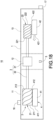
- step N1 of FIG. 14 and in FIG. 18 when the length of the second slide valve 42 between the second suction end 221 and the second discharge end 222 is equal to 80% of the total length of the second slide valve 42, and the intermediate pressure sensor 5 detects that the interior pressure of the intermediate-pressure chamber 12 is still higher than the preset intermediate pressure, at this point, the lubricating fluid is unable to be smoothly injected into the intermediate-pressure chamber 12.
- the controller 6 then controls the second slide valve 42 to continue moving towards the second suction end 221, meaning the second slide valve 42 covers more than 80% of the screw area of the pair of second screws 22, thereby increasing the suction volume of the pair of second screws 22 until the intermediate pressure sensor 5 detects that the interior pressure of the intermediate-pressure chamber 12 is equal to the preset intermediate pressure.
- the controller 6 controls the second slide valve 42 to move from the second suction end 221 towards the second discharge end 222, thereby decreasing the suction volume of the pair of second screws 22 until the interior pressure of the intermediate-pressure chamber 12 is equal to the preset intermediate pressure.
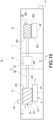
- step N2 of FIG. 14 and in FIG. 19 when the second slide valve 42 covers the second suction end 221 and the interior pressure of the intermediate-pressure chamber 12 remains above the preset intermediate pressure, the controller 6 controls the first slide valve 41 to move away from the first suction end 211 towards the first discharge end 212, thereby decreasing the suction volume of the pair of first screws 21 until the intermediate pressure sensor 5 detects that the interior pressure of the intermediate-pressure chamber 12 is equal to the preset intermediate pressure.
- steps N1 and N2 are special cases and may not always occur. Steps N1 and N2 may be omitted depending on the actual operating method of the fluid machine 10 of this disclosure.
- the drive module 3 first reduces the speed of one of the first screws 21 and one of the second screws 22 to a low rotational speed. This means the rotational speed of the pair of first screws 21 and the pair of second screws 22 gradually decreases from the preset rotational speed to between one-third to one-half of the preset rotational speed, achieving a low rotational speed between 400-2100 rpm.
- these specifics are not limiting to the present disclosure.
- the drive module 3 is then stopped, and after one of the first screws 21 and one of the second screws 22 stop rotating, the lubricating fluid ceases to be injected into the intermediate-pressure chamber 12 and the high-pressure chamber 13.
- the first radial notch 412 is positioned between the first suction end 211 and the midpoint of the pair of first screws 21.
- a related-art fluid machine has not taken into account the interior pressure of the intermediate-pressure chamber, leading to situations where, when the interior pressure of the intermediate-pressure chamber is too high, an economizer connected to both the intermediate-pressure chamber and the high-pressure chamber cannot inject the lubricating fluid. This results in abnormal oil supply to the second screws, thereby reducing efficiency.
- the controller 6 of this disclosure adjusts the positions of the first slide valve 41 and the second slide valve 42 relative to the pair of first screws 21 and the pair of second screws 22, respectively, based on the rotational speeds of the first and second screws 21, 22 and the interior pressure values of the intermediate-pressure chamber 12.
- This adjustment regulates the interior pressure of the intermediate-pressure chamber 12 to maintain the interior pressure at a preset intermediate pressure, ensuring that the lubricating fluid is steadily injected into the intermediate-pressure chamber 12 and the high-pressure chamber 13.
- the lubricating fluid Once the lubricating fluid enters the intermediate-pressure chamber 12 and the high-pressure chamber 13, the lubricating fluid continues to lubricate the second screw 22 with the fluid flow, achieving good operational efficiency for the fluid machine 10 of this disclosure.
Landscapes
- Engineering & Computer Science (AREA)
- Mechanical Engineering (AREA)
- General Engineering & Computer Science (AREA)
- Applications Or Details Of Rotary Compressors (AREA)
Applications Claiming Priority (1)
| Application Number | Priority Date | Filing Date | Title |
|---|---|---|---|
| TW112122808A TWI856706B (zh) | 2023-06-17 | 2023-06-17 | 流體機械及其操作方法 |
Publications (2)
| Publication Number | Publication Date |
|---|---|
| EP4477885A2 true EP4477885A2 (de) | 2024-12-18 |
| EP4477885A3 EP4477885A3 (de) | 2025-02-26 |
Family
ID=91076525
Family Applications (1)
| Application Number | Title | Priority Date | Filing Date |
|---|---|---|---|
| EP24175460.5A Pending EP4477885A3 (de) | 2023-06-17 | 2024-05-13 | Fluidmaschine und betriebsverfahren dafür |
Country Status (4)
| Country | Link |
|---|---|
| US (1) | US12140143B1 (de) |
| EP (1) | EP4477885A3 (de) |
| CN (1) | CN119146054A (de) |
| TW (1) | TWI856706B (de) |
Families Citing this family (1)
| Publication number | Priority date | Publication date | Assignee | Title |
|---|---|---|---|---|
| TWI867585B (zh) * | 2023-06-17 | 2024-12-21 | 復盛股份有限公司 | 雙段冷媒壓縮機及其操作方法 |
Family Cites Families (10)
| Publication number | Priority date | Publication date | Assignee | Title |
|---|---|---|---|---|
| JP4265577B2 (ja) * | 2005-06-30 | 2009-05-20 | 日立アプライアンス株式会社 | 二段スクリュー圧縮機 |
| JP5634228B2 (ja) * | 2010-11-12 | 2014-12-03 | 三菱電機株式会社 | スクリュー冷凍機 |
| JP5261466B2 (ja) * | 2010-12-06 | 2013-08-14 | 株式会社神戸製鋼所 | Bog多段容積型圧縮機の運転制御方法 |
| JP2013209953A (ja) * | 2012-03-30 | 2013-10-10 | Kobe Steel Ltd | 2段圧縮装置 |
| JP6385708B2 (ja) * | 2014-04-18 | 2018-09-05 | 日立ジョンソンコントロールズ空調株式会社 | スクリュー圧縮機 |
| US10808699B2 (en) * | 2017-09-28 | 2020-10-20 | Ingersoll-Rand Industrial U.S., Inc. | Suction side slide valve for a screw compressor |
| CN108167186B (zh) * | 2018-03-05 | 2024-07-12 | 珠海格力电器股份有限公司 | 螺杆压缩机及空调机组 |
| TWI681122B (zh) * | 2018-09-12 | 2020-01-01 | 復盛股份有限公司 | 流體機械 |
| US10876531B2 (en) * | 2018-12-26 | 2020-12-29 | Trane International Inc. | Lubricant injection for a screw compressor |
| CN110566461A (zh) * | 2019-09-11 | 2019-12-13 | 珠海格力电器股份有限公司 | 双级压缩机及双级压缩机的控制方法及空调机组 |
-
2023
- 2023-06-17 TW TW112122808A patent/TWI856706B/zh active
- 2023-06-26 CN CN202310759625.5A patent/CN119146054A/zh active Pending
-
2024
- 2024-05-07 US US18/656,887 patent/US12140143B1/en active Active
- 2024-05-13 EP EP24175460.5A patent/EP4477885A3/de active Pending
Also Published As
| Publication number | Publication date |
|---|---|
| EP4477885A3 (de) | 2025-02-26 |
| US12140143B1 (en) | 2024-11-12 |
| CN119146054A (zh) | 2024-12-17 |
| TW202500866A (zh) | 2025-01-01 |
| TWI856706B (zh) | 2024-09-21 |
Similar Documents
| Publication | Publication Date | Title |
|---|---|---|
| US8858192B2 (en) | Screw compressor | |
| US4351160A (en) | Capacity control systems for screw compressor based water chillers | |
| CN100406738C (zh) | 可变内部容积比式变频螺杆压缩机 | |
| KR100345843B1 (ko) | 스크류 압축장치와 그 운전 제어방법 | |
| US8491280B2 (en) | Oil-flooded screw compressor, motor drive system, and motor control device | |
| US7891955B2 (en) | Compressor having a dual slide valve assembly | |
| US6659729B2 (en) | Screw compressor equipment for accommodating low compression ratio and pressure variation and the operation method thereof | |
| US8337183B2 (en) | Oil return valve for a scroll compressor | |
| US6881040B2 (en) | Multi-stage screw compressor unit accommodating high suction pressure and pressure fluctuations and method of operation thereof | |
| JPH0249994A (ja) | 回転式圧縮機 | |
| JPS6059439B2 (ja) | 確実容積型回転ねじ圧縮機 | |
| KR940000217B1 (ko) | 스크류 압축장치 및 그 제어장치 | |
| US12140143B1 (en) | Fluid machine and operating method thereof | |
| JP2008095684A (ja) | 軸方向剪断力軽減装置を備えた、オイル溢流式のスクリュー圧縮機 | |
| EP3225848A1 (de) | Schraubenverdichter und kühlzyklusvorrichtung | |
| JP5078680B2 (ja) | ターボ圧縮機およびターボ冷凍機 | |
| US20230184475A1 (en) | Refrigeration cycle apparatus | |
| CN115875264B (zh) | 一种泵体组件、压缩机及空调器 | |
| CN216812148U (zh) | 螺杆压缩机以及空调设备 | |
| JP2018115643A (ja) | 多段オイルフリースクリュ圧縮機の容量制御方法及び多段オイルフリースクリュ圧縮機 | |
| JPS6330516B2 (de) | ||
| JPH0794827B2 (ja) | スクリュ圧縮機 | |
| CN121511357A (zh) | 用于对无油压缩式压缩机进行供给的油路和用于为这种压缩机供油而调节油参数的方法 | |
| JPH0320600B2 (de) | ||
| CN119146053A (zh) | 双段冷媒压缩机及其操作方法 |
Legal Events
| Date | Code | Title | Description |
|---|---|---|---|
| PUAI | Public reference made under article 153(3) epc to a published international application that has entered the european phase |
Free format text: ORIGINAL CODE: 0009012 |
|
| STAA | Information on the status of an ep patent application or granted ep patent |
Free format text: STATUS: THE APPLICATION HAS BEEN PUBLISHED |
|
| AK | Designated contracting states |
Kind code of ref document: A2 Designated state(s): AL AT BE BG CH CY CZ DE DK EE ES FI FR GB GR HR HU IE IS IT LI LT LU LV MC ME MK MT NL NO PL PT RO RS SE SI SK SM TR |
|
| PUAL | Search report despatched |
Free format text: ORIGINAL CODE: 0009013 |
|
| AK | Designated contracting states |
Kind code of ref document: A3 Designated state(s): AL AT BE BG CH CY CZ DE DK EE ES FI FR GB GR HR HU IE IS IT LI LT LU LV MC ME MK MT NL NO PL PT RO RS SE SI SK SM TR |
|
| RIC1 | Information provided on ipc code assigned before grant |
Ipc: F04C 28/18 20060101ALI20250121BHEP Ipc: F04C 23/00 20060101ALI20250121BHEP Ipc: F04C 18/16 20060101AFI20250121BHEP |
|
| STAA | Information on the status of an ep patent application or granted ep patent |
Free format text: STATUS: REQUEST FOR EXAMINATION WAS MADE |
|
| 17P | Request for examination filed |
Effective date: 20250710 |