EP4477583A2 - Flexible netzartige struktur - Google Patents
Flexible netzartige struktur Download PDFInfo
- Publication number
- EP4477583A2 EP4477583A2 EP24210587.2A EP24210587A EP4477583A2 EP 4477583 A2 EP4477583 A2 EP 4477583A2 EP 24210587 A EP24210587 A EP 24210587A EP 4477583 A2 EP4477583 A2 EP 4477583A2
- Authority
- EP
- European Patent Office
- Prior art keywords
- reticular structure
- housings
- flexible reticular
- module
- modules
- Prior art date
- Legal status (The legal status is an assumption and is not a legal conclusion. Google has not performed a legal analysis and makes no representation as to the accuracy of the status listed.)
- Pending
Links
Images

Classifications
-
- B—PERFORMING OPERATIONS; TRANSPORTING
- B65—CONVEYING; PACKING; STORING; HANDLING THIN OR FILAMENTARY MATERIAL
- B65H—HANDLING THIN OR FILAMENTARY MATERIAL, e.g. SHEETS, WEBS, CABLES
- B65H35/00—Delivering articles from cutting or line-perforating machines; Article or web delivery apparatus incorporating cutting or line-perforating devices, e.g. adhesive tape dispensers
- B65H35/04—Delivering articles from cutting or line-perforating machines; Article or web delivery apparatus incorporating cutting or line-perforating devices, e.g. adhesive tape dispensers from or with transverse cutters or perforators
- B65H35/06—Delivering articles from cutting or line-perforating machines; Article or web delivery apparatus incorporating cutting or line-perforating devices, e.g. adhesive tape dispensers from or with transverse cutters or perforators from or with blade, e.g. shear-blade, cutters or perforators
-
- B—PERFORMING OPERATIONS; TRANSPORTING
- B26—HAND CUTTING TOOLS; CUTTING; SEVERING
- B26D—CUTTING; DETAILS COMMON TO MACHINES FOR PERFORATING, PUNCHING, CUTTING-OUT, STAMPING-OUT OR SEVERING
- B26D7/00—Details of apparatus for cutting, cutting-out, stamping-out, punching, perforating, or severing by means other than cutting
- B26D7/20—Cutting beds
-
- B—PERFORMING OPERATIONS; TRANSPORTING
- B65—CONVEYING; PACKING; STORING; HANDLING THIN OR FILAMENTARY MATERIAL
- B65G—TRANSPORT OR STORAGE DEVICES, e.g. CONVEYORS FOR LOADING OR TIPPING, SHOP CONVEYOR SYSTEMS OR PNEUMATIC TUBE CONVEYORS
- B65G17/00—Conveyors having an endless traction element, e.g. a chain, transmitting movement to a continuous or substantially-continuous load-carrying surface or to a series of individual load-carriers; Endless-chain conveyors in which the chains form the load-carrying surface
- B65G17/06—Conveyors having an endless traction element, e.g. a chain, transmitting movement to a continuous or substantially-continuous load-carrying surface or to a series of individual load-carriers; Endless-chain conveyors in which the chains form the load-carrying surface having a load-carrying surface formed by a series of interconnected, e.g. longitudinal, links, plates, or platforms
- B65G17/08—Conveyors having an endless traction element, e.g. a chain, transmitting movement to a continuous or substantially-continuous load-carrying surface or to a series of individual load-carriers; Endless-chain conveyors in which the chains form the load-carrying surface having a load-carrying surface formed by a series of interconnected, e.g. longitudinal, links, plates, or platforms the surface being formed by the traction element
-
- B—PERFORMING OPERATIONS; TRANSPORTING
- B65—CONVEYING; PACKING; STORING; HANDLING THIN OR FILAMENTARY MATERIAL
- B65G—TRANSPORT OR STORAGE DEVICES, e.g. CONVEYORS FOR LOADING OR TIPPING, SHOP CONVEYOR SYSTEMS OR PNEUMATIC TUBE CONVEYORS
- B65G17/00—Conveyors having an endless traction element, e.g. a chain, transmitting movement to a continuous or substantially-continuous load-carrying surface or to a series of individual load-carriers; Endless-chain conveyors in which the chains form the load-carrying surface
- B65G17/24—Conveyors having an endless traction element, e.g. a chain, transmitting movement to a continuous or substantially-continuous load-carrying surface or to a series of individual load-carriers; Endless-chain conveyors in which the chains form the load-carrying surface comprising a series of rollers which are moved, e.g. over a supporting surface, by the traction element to effect conveyance of loads or load-carriers
-
- B—PERFORMING OPERATIONS; TRANSPORTING
- B65—CONVEYING; PACKING; STORING; HANDLING THIN OR FILAMENTARY MATERIAL
- B65G—TRANSPORT OR STORAGE DEVICES, e.g. CONVEYORS FOR LOADING OR TIPPING, SHOP CONVEYOR SYSTEMS OR PNEUMATIC TUBE CONVEYORS
- B65G17/00—Conveyors having an endless traction element, e.g. a chain, transmitting movement to a continuous or substantially-continuous load-carrying surface or to a series of individual load-carriers; Endless-chain conveyors in which the chains form the load-carrying surface
- B65G17/30—Details; Auxiliary devices
- B65G17/32—Individual load-carriers
- B65G17/34—Individual load-carriers having flat surfaces, e.g. platforms, grids, forks
-
- B—PERFORMING OPERATIONS; TRANSPORTING
- B65—CONVEYING; PACKING; STORING; HANDLING THIN OR FILAMENTARY MATERIAL
- B65G—TRANSPORT OR STORAGE DEVICES, e.g. CONVEYORS FOR LOADING OR TIPPING, SHOP CONVEYOR SYSTEMS OR PNEUMATIC TUBE CONVEYORS
- B65G17/00—Conveyors having an endless traction element, e.g. a chain, transmitting movement to a continuous or substantially-continuous load-carrying surface or to a series of individual load-carriers; Endless-chain conveyors in which the chains form the load-carrying surface
- B65G17/30—Details; Auxiliary devices
- B65G17/38—Chains or like traction elements; Connections between traction elements and load-carriers
- B65G17/40—Chains acting as load-carriers
-
- B—PERFORMING OPERATIONS; TRANSPORTING
- B65—CONVEYING; PACKING; STORING; HANDLING THIN OR FILAMENTARY MATERIAL
- B65H—HANDLING THIN OR FILAMENTARY MATERIAL, e.g. SHEETS, WEBS, CABLES
- B65H2404/00—Parts for transporting or guiding the handled material
- B65H2404/50—Surface of the elements in contact with the forwarded or guided material
- B65H2404/56—Flexible surface
- B65H2404/561—Bristles, brushes
Definitions
- the present invention relates to a flexible reticular structure, in particular to a modular flexible reticular structure whereon additional elements can be assembled, and which has incorporated rolling elements to facilitate the movement thereof.
- Flexible reticular structures are used in different applications, and comprise a movable surface for conveying goods.
- one type of flexible reticular structure is used to move laminar material for the cutting thereof by means of a head, said laminar material being able to be paper or fabric.
- a base element is placed on the movable surface in order to enable the cutting of said laminar material.
- a problem associated with conventional conveyance systems is that in the case of repair or maintenance it is necessary to remove or substitute all or a large part of the movable surface, with the subsequent economic cost associated.
- the movement of said movable surface is operated by at least one motor, or a pair of motors, if the movable surface advances in two directions.
- Document EP 3 106 411 A1 of the same holder as the present application, describes a flexible reticular structure comprising a movable surface the movement of which is operated by means of operating means, said surface being formed by a plurality of modules linked to one another by means of attachment rods, each of said rods being housed in holes provided in at least two of said modules.
- said flexible reticular structure is not optimised to be operated when it has to convey high loads.
- EP 2 295 348 A2 discloses a chain conveyor comprising a conveyor surface, and support rollers, which are arranged below the conveyor surface.
- the support rollers support the conveyor surface on a carrier in a rolling manner.
- the support rollers are arranged in a predetermined distribution below the conveyor surface and are located in the vicinity of outer edges in a transverse direction.
- the flexible reticular structure of the invention resolves the drawbacks mentioned and has other advantages which are described below.
- the flexible reticular structure according to the present invention is defined in claim 1, and it comprises a movable surface the movement of which is operated by operating means, said surface being formed by a plurality of modules linked to one another by means of attachment rods, each of said rods being housed in holes provided in at least two of said modules, and each module comprises at least one wheel assembled in at least one of said rods.
- the flexible reticular structure according to the present invention can be moved easily.
- each module comprises tabs wherein the holes are located, two adjacent tabs defining a housing for placing a wheel.
- the wheels are housed in spaces which would otherwise be wasted.
- said tabs prevent the lateral movement of said wheels, thereby keeping them from moving from the established position thereof and leaving them conveniently distributed throughout the entire structure.
- said tabs define first housings and second housings, the length of the first housings being greater than the length of the second housings. Thanks to this characteristic, the tabs of the second housings can be placed between the tabs of the first housings of an adjacent module, thereby enabling the attachment rod of said modules to remain right at the intersection of said modules.
- said first housings with a greater length if there is more than one, would be located facing each other; and in the same manner said second housings with a smaller length would also be located facing each other, next to the first housings.
- Said distribution enables the assembly of the different modules to be carried out in a linear manner and in an alternating manner.
- the alternating assembly of the different modules gives overall greater stiffness to the flexible reticular structure.
- the wheel is a roller which substantially encompasses the entire length of the housing, and said roller can include a bearing therein to reduce the friction between the roller and the rod.
- each module is made up of a plurality of transverse and longitudinal dividers which define rectangular and/or quadrangular cells.
- a module is achieved with reduced weight, which also facilitates the movement of the flexible reticular structure.
- said rectangular and/or quadrangular cells enable a greater passage of fluids through said module, for example, air, being very useful in applications which, for example, have to work with a vacuum on the upper surface of the flexible reticular structure, and likewise creating a self-cleaning effect.
- each module preferably comprises a recessed portion in the middle part and/or on the ends thereof for placing the operating means.
- Said modules also advantageously comprise holes for fastening corresponding additional elements on the upper part of the flexible reticular structure, for example, brushes provided with bristles.
- Said additional elements enable the surface to be adapted according to different applications.
- Said fastening holes of corresponding additional elements can be distributed regularly or irregularly. It is obvious for a person skilled in the art that said additional elements can be any element, in addition to bristle brushes, which can facilitate conveyance of the material to be handled according to the application.
- Said additional elements can be fastened by any other fastening means, in addition to the fastening holes, which can be screws, adhesive, etc.
- Said operating means comprise an operating element for moving said movable surface in both directions.
- said operating means (motors or equivalents) can operate along the width of the entire structure using several drive means (pinions, gears or equivalents), better distributing forces on the flexible reticular structure and not only on the sides.
- Figure 1 shows the perspective view of a movable surface, generally indicated by the numerical reference 1, of a flexible reticular structure according to the present invention.
- Said movable surface 1 is preferably operated by means of an operating element 2, which can be seen in figure 6 , in the two directions thereof.
- said surface 1 is modular, meaning, it is made up of a plurality of modules 3 linked to one another.
- the linking or coupling of said modules is carried out by means of longitudinal rods 5, which are introduced into holes 6 of said modules 3.
- said holes 6 are arranged in tabs 7 of the modules 3, which project laterally from said modules 3.
- each module 3 comprises at least one wheel 4, which is assembled in at least one of said longitudinal rods 5.
- each module 3 comprises four wheels 4, two on each side of the module 3.
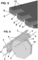
- each wheel 4 is placed in a first housing 8 or a second housing 9 defined between two adjacent tabs 7, as seen in figure 2 .
- the length of the first housings 8 is greater than the length of the second housings 9. Furthermore, each wheel 4 substantially occupies the entire length of the respective housing 8, 9.
- each wheel 4 is a roller, which can include at least one bearing therein to decrease the friction between the wheel 4 and the rod 5.
- each module 3 is made up of a plurality of longitudinal and transverse dividers which define rectangular, quadrangular and/or polygonal cells, maximising the structural resistance thereof and reducing the weight of each module 3 as much as possible. Furthermore, this characteristic enables the circulation of fluid through said module.
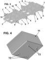
- said modules 3 comprise fastening holes 10, although they could comprise any suitable fastening or coupling means (shown as square holes, these can be any anchoring method: round holes, square holes, clips, guides, screws, glue, etc.).
- the brushes include clips 13 in the lower surface which fit into the fastening holes 10, as seen in figure 4 .
- said additional elements are brushes 11 provided with bristles which couple onto said modules 3.
- each module 3 comprises protuberances 14, which in the assembly position will press on the lower surface of said brushes 11 so that the bristles open (desired effect in the applications for cutting laminar material).
- These brushes 11 are preferably used to act as a base for a laminar material, such as paper or fabric, which will be cut by means of a suitable cutting device.
- the bristles of said brushes 11 will act as a support for the laminar material, but the blade of the cutting device will be able to pass between them.
- Figure 6 shows a plurality of modules 3 assembled on an operating element, which makes up part of the operating means 2, for operating the movement of the movable surface 1.
- each module 3 comprises at least one recessed portion 12 in the middle part thereof and/or on the ends thereof to house the operating element.
- Said operating element has a polygonal shape, seen in a plan view, and comprises grooves 15 in the vertices thereof to house the rods 5. To do so, the wheels 4 of the modules 3 do not occupy the entire length thereof, rather they define a free separation between the housings 8, 9.
Landscapes
- Engineering & Computer Science (AREA)
- Mechanical Engineering (AREA)
- Life Sciences & Earth Sciences (AREA)
- Forests & Forestry (AREA)
- Handcart (AREA)
- Motorcycle And Bicycle Frame (AREA)
- Chain Conveyers (AREA)
- Flexible Shafts (AREA)
- Brushes (AREA)
- Package Frames And Binding Bands (AREA)
- Prostheses (AREA)
Applications Claiming Priority (2)
| Application Number | Priority Date | Filing Date | Title |
|---|---|---|---|
| ES201830162A ES2723748B2 (es) | 2018-02-23 | 2018-02-23 | Estructura reticular flexible |
| EP19382078.4A EP3530594B1 (de) | 2018-02-23 | 2019-02-04 | Flexible retikuläre struktur |
Related Parent Applications (1)
| Application Number | Title | Priority Date | Filing Date |
|---|---|---|---|
| EP19382078.4A Division EP3530594B1 (de) | 2018-02-23 | 2019-02-04 | Flexible retikuläre struktur |
Publications (2)
| Publication Number | Publication Date |
|---|---|
| EP4477583A2 true EP4477583A2 (de) | 2024-12-18 |
| EP4477583A3 EP4477583A3 (de) | 2025-03-19 |
Family
ID=65496733
Family Applications (2)
| Application Number | Title | Priority Date | Filing Date |
|---|---|---|---|
| EP24210587.2A Pending EP4477583A3 (de) | 2018-02-23 | 2019-02-04 | Flexible netzartige struktur |
| EP19382078.4A Active EP3530594B1 (de) | 2018-02-23 | 2019-02-04 | Flexible retikuläre struktur |
Family Applications After (1)
| Application Number | Title | Priority Date | Filing Date |
|---|---|---|---|
| EP19382078.4A Active EP3530594B1 (de) | 2018-02-23 | 2019-02-04 | Flexible retikuläre struktur |
Country Status (11)
| Country | Link |
|---|---|
| US (1) | US10661996B2 (de) |
| EP (2) | EP4477583A3 (de) |
| JP (1) | JP6918037B2 (de) |
| CN (1) | CN110182641B (de) |
| AU (1) | AU2019201040A1 (de) |
| BR (1) | BR102019003452B1 (de) |
| ES (2) | ES2723748B2 (de) |
| MX (1) | MX2019001524A (de) |
| PL (1) | PL3530594T3 (de) |
| RS (1) | RS66273B1 (de) |
| RU (1) | RU2721213C1 (de) |
Families Citing this family (4)
| Publication number | Priority date | Publication date | Assignee | Title |
|---|---|---|---|---|
| EP4005951B1 (de) * | 2020-11-30 | 2023-04-26 | Regina Catene Calibrate S.p.A. | Modulares rollenförderbandmodul und durch mehrere solcher module gebildetes modulares förderband |
| US12208965B2 (en) | 2021-02-25 | 2025-01-28 | Motoveyo Corporation | Conveyor system and drive system for same |
| EP4298039A1 (de) * | 2021-02-25 | 2024-01-03 | Motoveyo Corporation | Fördersystem und antriebssystem dafür |
| EP4071090A1 (de) * | 2021-04-08 | 2022-10-12 | Open Mind Ventures, S.L.U. | Bürstenmodul für förderbänder |
Citations (2)
| Publication number | Priority date | Publication date | Assignee | Title |
|---|---|---|---|---|
| EP2295348A2 (de) | 2009-09-09 | 2011-03-16 | Krones AG | Förderkette |
| EP3106411A1 (de) | 2015-06-19 | 2016-12-21 | Manufacturas y Transformados AB, S.L. | Flexible retikuläre struktur |
Family Cites Families (24)
| Publication number | Priority date | Publication date | Assignee | Title |
|---|---|---|---|---|
| GB856532A (en) * | 1958-07-07 | 1960-12-21 | Ashworth Bros Inc | Heavy duty flat wire conveyor belt |
| US4512460A (en) * | 1983-03-30 | 1985-04-23 | Glasstech, Inc. | Glass sheet roller conveyor including antifriction drive chain |
| US5189936A (en) * | 1991-04-05 | 1993-03-02 | Gerber Garment Technology, Inc. | Conveyor for supporting and advancing sheet material and cutting machine including such conveyor |
| US5558204A (en) * | 1993-05-05 | 1996-09-24 | Maryland Wire Belts, Inc. | Modular components and weld-free belting assembly |
| JP2000016551A (ja) * | 1998-06-30 | 2000-01-18 | Eastern Giken Kk | コンベア装置 |
| JP3448220B2 (ja) * | 1998-07-29 | 2003-09-22 | 株式会社椿本チエイン | スラットコンベヤチェーン |
| US6364095B1 (en) * | 2000-04-13 | 2002-04-02 | Span Tech Llc | Modular conveyor system with side flexing belt having roller support |
| JP2004313501A (ja) * | 2003-04-17 | 2004-11-11 | System Create:Kk | 飲食物の循環搬送装置 |
| GB0316919D0 (en) * | 2003-07-18 | 2003-08-27 | Molins Plc | Improved conveyor belt chain link |
| US6814223B1 (en) * | 2003-09-25 | 2004-11-09 | Laitram, L.L.C. | Self-closing hinge rod retention in modular plastic conveyor belts |
| US6932211B2 (en) * | 2003-12-15 | 2005-08-23 | Rexnord Industries, Inc. | Modular conveying assembly with stub mounted in-line rollers |
| JP2005306536A (ja) * | 2004-04-20 | 2005-11-04 | Star Techno Kk | 搬送装置及び搬送システム |
| DE102004021262A1 (de) * | 2004-04-30 | 2005-11-17 | Sander Hansen A/S | Pasteur mit Förderband |
| US7097030B2 (en) * | 2004-10-19 | 2006-08-29 | Laitram, L.L.C. | Long, flexible conveyor belt modules in modular plastic conveyor belts |
| DE102005030116A1 (de) * | 2005-06-28 | 2007-01-18 | Winterhalter Gastronom Gmbh | Transportband für eine Durchlauf-Geschirrspülmaschine sowie Segmente für ein solches Transportband |
| NL1030701C2 (nl) * | 2005-12-19 | 2007-06-20 | Rexnord Flattop Europe Bv | Module voor een transportmat, modulaire transportmat en transporteur. |
| DE102006004807A1 (de) * | 2006-01-24 | 2007-08-02 | Hauni Maschinenbau Ag | Förderkette als kurvengängige und laufrollenfreie Tragförderkette |
| NL1032089C1 (nl) * | 2006-04-05 | 2007-10-08 | Rexnord Flattop Europe Bv | Transportmatmodule, transportmat en transporteur. |
| US7775345B2 (en) * | 2008-03-27 | 2010-08-17 | Laitram, L.L.C. | Conveyor and belt with clutch-driven flights |
| US7850001B2 (en) * | 2008-04-21 | 2010-12-14 | Habasit Ag | Low friction roller belt |
| WO2010124719A1 (en) * | 2009-04-27 | 2010-11-04 | Habasit Ag | Low friction roller belt |
| US8701871B2 (en) * | 2011-03-25 | 2014-04-22 | Laitram, L.L.C. | Belt conveyor with snagless retractable flights |
| CA2858083C (en) * | 2011-12-06 | 2018-06-12 | Ashworth Bros., Inc. | Conveyor belt with alignment features |
| WO2016095933A1 (en) * | 2014-12-19 | 2016-06-23 | Ammeraal Beltech Modular A/S | Modular belt link |
-
2018
- 2018-02-23 ES ES201830162A patent/ES2723748B2/es active Active
-
2019
- 2019-02-04 PL PL19382078.4T patent/PL3530594T3/pl unknown
- 2019-02-04 RS RS20241376A patent/RS66273B1/sr unknown
- 2019-02-04 EP EP24210587.2A patent/EP4477583A3/de active Pending
- 2019-02-04 ES ES19382078T patent/ES2999024T3/es active Active
- 2019-02-04 EP EP19382078.4A patent/EP3530594B1/de active Active
- 2019-02-06 MX MX2019001524A patent/MX2019001524A/es unknown
- 2019-02-14 AU AU2019201040A patent/AU2019201040A1/en not_active Abandoned
- 2019-02-20 BR BR102019003452-1A patent/BR102019003452B1/pt active IP Right Grant
- 2019-02-22 CN CN201910132631.1A patent/CN110182641B/zh active Active
- 2019-02-22 RU RU2019105016A patent/RU2721213C1/ru active
- 2019-02-22 US US16/282,672 patent/US10661996B2/en active Active
- 2019-02-25 JP JP2019031420A patent/JP6918037B2/ja active Active
Patent Citations (2)
| Publication number | Priority date | Publication date | Assignee | Title |
|---|---|---|---|---|
| EP2295348A2 (de) | 2009-09-09 | 2011-03-16 | Krones AG | Förderkette |
| EP3106411A1 (de) | 2015-06-19 | 2016-12-21 | Manufacturas y Transformados AB, S.L. | Flexible retikuläre struktur |
Also Published As
| Publication number | Publication date |
|---|---|
| BR102019003452B1 (pt) | 2023-11-14 |
| RU2721213C1 (ru) | 2020-05-18 |
| ES2999024T3 (en) | 2025-02-24 |
| BR102019003452A2 (pt) | 2019-10-29 |
| EP3530594B1 (de) | 2024-11-13 |
| EP3530594A1 (de) | 2019-08-28 |
| CN110182641B (zh) | 2022-03-04 |
| US20190263594A1 (en) | 2019-08-29 |
| PL3530594T3 (pl) | 2025-04-14 |
| JP2019142719A (ja) | 2019-08-29 |
| EP4477583A3 (de) | 2025-03-19 |
| JP6918037B2 (ja) | 2021-08-11 |
| ES2723748B2 (es) | 2020-02-28 |
| MX2019001524A (es) | 2019-09-04 |
| CN110182641A (zh) | 2019-08-30 |
| AU2019201040A1 (en) | 2019-09-12 |
| RS66273B1 (sr) | 2025-01-31 |
| US10661996B2 (en) | 2020-05-26 |
| ES2723748A1 (es) | 2019-08-30 |
Similar Documents
| Publication | Publication Date | Title |
|---|---|---|
| EP3530594B1 (de) | Flexible retikuläre struktur | |
| US9731902B2 (en) | Flexible reticular structure | |
| EP2611715B1 (de) | Pick-to-window | |
| RU2713130C2 (ru) | Гибридная система транспортировки предметов | |
| US20130270075A1 (en) | Plastic, modular and self-engaging bristle brush | |
| JP2025122250A (ja) | 複数の毛ブラシにより形成されたコンベアベルト | |
| AU2016100077A4 (en) | Vibratory apparatus with deck panel and assembly method | |
| EP2050697B1 (de) | Fördervorrichtung zum Transportieren, Sortieren und/oder Handhaben von Objekten | |
| CN103128185A (zh) | 搬运装置及采用该搬运装置的冲压设备 | |
| US10870541B2 (en) | Logistics trolley and production line using the same | |
| DE102008002831A1 (de) | Vorrichtung und Verfahren zum Überführen von Gebindelagen in eine Beladestation | |
| ATE469070T1 (de) | Verteilungs- und zwischenlagerungssystem für transporteinheiten | |
| JP6072123B2 (ja) | 青果物の搬送用コンベヤベルト | |
| US20240059493A1 (en) | Conveyor belt formed by a plurality of said bristle brushes | |
| AT507691A3 (de) | Regalbauelement und ein solches enthaltendes regal | |
| CN210253934U (zh) | 一种用于金属板材切割上料的输送装置 | |
| US20080110720A1 (en) | Gravity Flow Track Using B-Deck Panel | |
| JP5730815B2 (ja) | 青果物の搬送用コンベヤベルト | |
| KR20230162180A (ko) | 제품 분류 이송 장치 | |
| EP1347497A3 (de) | Hordenhalter für Halbleiterscheiben | |
| CN107263756A (zh) | 一种多锯片仿形机的移料机构 | |
| CN105773064A (zh) | 一种改进的压花装置 |
Legal Events
| Date | Code | Title | Description |
|---|---|---|---|
| PUAI | Public reference made under article 153(3) epc to a published international application that has entered the european phase |
Free format text: ORIGINAL CODE: 0009012 |
|
| STAA | Information on the status of an ep patent application or granted ep patent |
Free format text: STATUS: THE APPLICATION HAS BEEN PUBLISHED |
|
| AC | Divisional application: reference to earlier application |
Ref document number: 3530594 Country of ref document: EP Kind code of ref document: P |
|
| AK | Designated contracting states |
Kind code of ref document: A2 Designated state(s): AL AT BE BG CH CY CZ DE DK EE ES FI FR GB GR HR HU IE IS IT LI LT LU LV MC MK MT NL NO PL PT RO RS SE SI SK SM TR |
|
| REG | Reference to a national code |
Ref country code: DE Ref legal event code: R079 Free format text: PREVIOUS MAIN CLASS: B65G0017400000 Ipc: B65G0017240000 |
|
| PUAL | Search report despatched |
Free format text: ORIGINAL CODE: 0009013 |
|
| AK | Designated contracting states |
Kind code of ref document: A3 Designated state(s): AL AT BE BG CH CY CZ DE DK EE ES FI FR GB GR HR HU IE IS IT LI LT LU LV MC MK MT NL NO PL PT RO RS SE SI SK SM TR |
|
| RIC1 | Information provided on ipc code assigned before grant |
Ipc: B65G 17/40 20060101ALI20250207BHEP Ipc: B65G 17/24 20060101AFI20250207BHEP |
|
| STAA | Information on the status of an ep patent application or granted ep patent |
Free format text: STATUS: REQUEST FOR EXAMINATION WAS MADE |
|
| 17P | Request for examination filed |
Effective date: 20250915 |