EP4477331A2 - Clamping device and method for transporting a container - Google Patents
Clamping device and method for transporting a container Download PDFInfo
- Publication number
- EP4477331A2 EP4477331A2 EP24201833.1A EP24201833A EP4477331A2 EP 4477331 A2 EP4477331 A2 EP 4477331A2 EP 24201833 A EP24201833 A EP 24201833A EP 4477331 A2 EP4477331 A2 EP 4477331A2
- Authority
- EP
- European Patent Office
- Prior art keywords
- clamp
- pair
- container
- arms
- clamp arms
- Prior art date
- Legal status (The legal status is an assumption and is not a legal conclusion. Google has not performed a legal analysis and makes no representation as to the accuracy of the status listed.)
- Pending
Links
Images

Classifications
-
- B—PERFORMING OPERATIONS; TRANSPORTING
- B65—CONVEYING; PACKING; STORING; HANDLING THIN OR FILAMENTARY MATERIAL
- B65G—TRANSPORT OR STORAGE DEVICES, e.g. CONVEYORS FOR LOADING OR TIPPING, SHOP CONVEYOR SYSTEMS OR PNEUMATIC TUBE CONVEYORS
- B65G47/00—Article or material-handling devices associated with conveyors; Methods employing such devices
- B65G47/74—Feeding, transfer, or discharging devices of particular kinds or types
- B65G47/90—Devices for picking-up and depositing articles or materials
- B65G47/907—Devices for picking-up and depositing articles or materials with at least two picking-up heads
-
- B—PERFORMING OPERATIONS; TRANSPORTING
- B65—CONVEYING; PACKING; STORING; HANDLING THIN OR FILAMENTARY MATERIAL
- B65G—TRANSPORT OR STORAGE DEVICES, e.g. CONVEYORS FOR LOADING OR TIPPING, SHOP CONVEYOR SYSTEMS OR PNEUMATIC TUBE CONVEYORS
- B65G47/00—Article or material-handling devices associated with conveyors; Methods employing such devices
- B65G47/74—Feeding, transfer, or discharging devices of particular kinds or types
- B65G47/84—Star-shaped wheels or devices having endless travelling belts or chains, the wheels or devices being equipped with article-engaging elements
- B65G47/846—Star-shaped wheels or wheels equipped with article-engaging elements
- B65G47/847—Star-shaped wheels or wheels equipped with article-engaging elements the article-engaging elements being grippers
-
- B—PERFORMING OPERATIONS; TRANSPORTING
- B08—CLEANING
- B08B—CLEANING IN GENERAL; PREVENTION OF FOULING IN GENERAL
- B08B9/00—Cleaning hollow articles by methods or apparatus specially adapted thereto
- B08B9/08—Cleaning containers, e.g. tanks
- B08B9/20—Cleaning containers, e.g. tanks by using apparatus into or on to which containers, e.g. bottles, jars, cans are brought
- B08B9/42—Cleaning containers, e.g. tanks by using apparatus into or on to which containers, e.g. bottles, jars, cans are brought the apparatus being characterised by means for conveying or carrying containers therethrough
- B08B9/426—Grippers for bottles
-
- B—PERFORMING OPERATIONS; TRANSPORTING
- B65—CONVEYING; PACKING; STORING; HANDLING THIN OR FILAMENTARY MATERIAL
- B65G—TRANSPORT OR STORAGE DEVICES, e.g. CONVEYORS FOR LOADING OR TIPPING, SHOP CONVEYOR SYSTEMS OR PNEUMATIC TUBE CONVEYORS
- B65G47/00—Article or material-handling devices associated with conveyors; Methods employing such devices
- B65G47/74—Feeding, transfer, or discharging devices of particular kinds or types
- B65G47/90—Devices for picking-up and depositing articles or materials
- B65G47/904—Devices for picking-up and depositing articles or materials provided with rotary movements only
-
- B—PERFORMING OPERATIONS; TRANSPORTING
- B65—CONVEYING; PACKING; STORING; HANDLING THIN OR FILAMENTARY MATERIAL
- B65G—TRANSPORT OR STORAGE DEVICES, e.g. CONVEYORS FOR LOADING OR TIPPING, SHOP CONVEYOR SYSTEMS OR PNEUMATIC TUBE CONVEYORS
- B65G2201/00—Indexing codes relating to handling devices, e.g. conveyors, characterised by the type of product or load being conveyed or handled
- B65G2201/02—Articles
- B65G2201/0235—Containers
- B65G2201/0244—Bottles
Definitions
- the invention relates to a clamping device for holding a container and a method for transporting a container.
- containers In container treatment plants for manufacturing, cleaning, filling, closing, etc. containers, containers can be held and transported through the plant using gripper or clamp devices.
- the DE 10 2005 014 838 A1 a clamp for holding vessels in vessel transport machines, with two clamp arms that can be moved relative to each other for opening and closing.
- Each clamp arm has a gripping arm and at least one clamp arm has a counter arm.
- the clamp arm is designed as a single piece with the gripping arm and counter arm so that the gripping arm is dimensionally stable and the counter arm is dimensionally elastic.
- the invention is based on the object of creating an improved technology for holding containers.
- the technology should also be able to hold containers in a process-safe and damage-free manner, the outer surface of which has differently shaped and/or differently sized sections.
- a clamping device e.g. double clamping device, double-deck clamping device or multiple clamping device for holding a container for a container treatment system (e.g. for producing, cleaning, testing, filling, closing, labeling, printing and/or packaging containers for liquid media, preferably drinks or liquid foodstuffs).
- the clamping device has a first (e.g. lower or upper) pair of clamping arms and a second (e.g. upper or lower) pair of clamping arms, which are arranged one above the other (e.g. directly) to hold the container at the same time, and which can be pivoted independently of one another (e.g. decoupled) (e.g. between an open position and a closed position), preferably coaxially (and/or about a, preferably common, pivot axis).
- the two pairs of clamp arms advantageously have an additional degree of freedom compared to conventional solutions due to the independent pivoting capability of each other.
- the clamping device advantageously enables a container to be held on different external shapes and/or external dimensions of the container. The number of incorrect grips can be reduced even with complex container shapes. This ultimately ensures higher product quality and greater process reliability. Overall, increased flexibility can be achieved with regard to different shapes and sizes of containers that can be held by the clamping device and thus processed in the container treatment system.
- the solution also allows containers with "normal" container shapes (for example with a cylindrical container body) to be handled. This means that, for example, a quick format change between cylindrical containers and contour containers can be carried out without having to change the clamping devices on the transport device. Particularly preferred embodiments are described below, with which the advantages mentioned can be achieved particularly effectively.
- the containers can be designed as bottles, cans, canisters, cartons, flacons, etc.
- the containers can have a drawn-in, bulbous, conical, sectionally tapering, sectionally widening or generally contoured (e.g. jacket or outer circumference) shape.
- the container may have a first outer peripheral portion and a second outer peripheral portion that are offset from each other with respect to a vertical axis of the container and that differ from each other in a size (e.g. cross-sectional size or diameter) and/or a shape.
- the container may be holdable or retained by the first pair of clamp arms at the first outer peripheral portion, and the container may be holdable or retained by the second pair of clamp arms at the second outer peripheral portion.
- the first pair of clamp arms may extend in a first horizontal plane and the second pair of clamp arms may extend in a second horizontal plane spaced from the first horizontal plane.
- the first pair of clamp arms has two first clamp arms, preferably coupled to one another (e.g. by means of a first actuating device), for applying to the container, which can be pivoted in opposite directions to one another (for example about a pivot pin of the clamping device).
- the second pair of clamp arms has two second clamp arms, preferably coupled to one another (e.g. by means of a second actuating device), for applying to the container, which can be pivoted in opposite directions to one another and independently of the two first clamp arms (for example about another pivot pin of the clamping device), preferably coaxially to the two first clamp arms.
- the two first clamp arms are formed separately from one another or are formed integrally with one another.
- the two second clamp arms can be formed separately from one another or are formed integrally with one another.
- first pair of clamp arms and the second pair of clamp arms are pivotable independently of one another such that the container can be held on different sized and/or differently shaped outer peripheral portions of the container when simultaneously held by the first pair of clamp arms and the second pair of clamp arms.
- first pair of clamp arms and the second pair of clamp arms can be pivoted independently of one another in such a way that a pivoting in (or closing) of the first pair of clamp arms, preferably brought about by pre-tensioning, is continued until it comes into contact with the container, even if a pivoting in of the second pair of clamp arms, preferably brought about by pre-tensioning, has already ended by coming into contact with the container.
- first pair of clamp arms and the second pair of clamp arms can be pivoted independently of one another in such a way that a pivoting (or opening) of the first pair of clamp arms, preferably brought about by actuation, takes place decoupled from a pivoting of the second pair of clamp arms, preferably brought about by actuation.
- first pair of clamp arms and the second pair of clamp arms are structurally identical and/or substantially mirror-symmetrical with respect to a horizontal plane.
- this can reduce the manufacturing costs of the clamping device and/or make assembly of the clamping device easier.
- the clamping device further comprises a clamp carrier, preferably substantially block-shaped and/or elongated, which pivotably supports the first clamp arm pair and the second clamp arm pair (e.g. on at least one pivot pin of the clamp carrier), preferably on opposite end regions of the clamp carrier (e.g. upper end region and lower end region of the clamp carrier with respect to a vertical axis of the clamping device).
- a clamp carrier preferably substantially block-shaped and/or elongated, which pivotably supports the first clamp arm pair and the second clamp arm pair (e.g. on at least one pivot pin of the clamp carrier), preferably on opposite end regions of the clamp carrier (e.g. upper end region and lower end region of the clamp carrier with respect to a vertical axis of the clamping device).
- the clamping device further comprises a first actuating device which is operatively connected to the first clamping arm pair in order to effect the pivoting (e.g. for opening) of the first clamping arm pair.
- the clamping device further comprises a second actuating device which is operatively connected to the second clamping arm pair in order to effect the pivoting (e.g. for opening) of the second clamping arm pair, preferably decoupled from the first actuating device.
- the actuating devices can advantageously be used to effect, for example, an opening or pivoting of the clamping arm pairs, which can also begin with a time delay in comparison to the clamping arm pairs or the actuating devices.
- first actuating device and the second actuating device are arranged (e.g. directly) one above the other and/or are of identical construction and/or are essentially mirror-symmetrical with respect to a horizontal plane and/or are carried by a clamp carrier of the clamping device and/or are designed as roller controls and/or are arranged between the first clamp arm pair and the second clamp arm pair.
- a compact design and/or reliable control of the actuating devices can be achieved.
- At least one of the first actuating device and the second actuating device has two pivot arms.
- the two pivot arms are arranged in a V-shape (or scissor-like) and/or can be moved back and forth in response to a mechanical input on the respective actuating device and/or on a Clamp arm of the respective clamp arm pair in operative connection is pivotally mounted (e.g. in a middle section of the clamp arms with respect to a longitudinal axis of the clamp arms).
- the two pivot arms are pivotally attached, preferably coaxially, to a displaceable transmission element.
- the transmission element can be displaceably mounted in a clamp carrier of the clamping device (e.g. in a plain bearing bush and/or a through hole (e.g. between a front and a rear side of the clamp carrier)) and/or be rod-shaped and/or carry an input element, preferably a rotatable roller or a sliding shoe (e.g. at the end and/or on a rear side/a side of the clamping device or the clamp carrier facing away from the container).
- the clamping device further comprises a first pre-tensioning element, preferably a helical spring, which pre-tensions the first pair of clamp arms, preferably for closing.
- the clamping device further comprises a second pre-tensioning element, preferably a helical spring, which pre-tensions the second pair of clamp arms, preferably for closing.
- the first pre-tensioning element and the second pre-tensioning element can preferably be arranged one above the other and/or extend parallel.
- the clamping arm pairs can thus be closed without any separate actuation being necessary.
- a holding force or clamping force can be generated to hold the container.
- the first and/or second biasing element can be designed as an elastic element, e.g. a spring (e.g. coil spring or U-spring) or a rubber piece, or as a magnet.
- At least one of the first pre-tensioning element and the second pre-tensioning element is supported on a clamp carrier of the clamping device (e.g. on a rear side of the clamp carrier) and/or on an actuating device of the clamping device (e.g. on a transmission element of the actuating device).
- at least one of the first pre-tensioning element and the second pre-tensioning element surrounds a section (e.g. the transmission element) of an actuating device of the clamping device (e.g. coaxially) and/or is arranged on a side of a clamp carrier of the clamping device facing away from the container.
- a further aspect relates to a (e.g. linear or carousel) transport device, preferably a rotatable clamp star, for containers for a container treatment plant.
- the transport device has at least one clamp device as disclosed herein.
- clamping devices as disclosed herein are included, which are arranged, for example, distributed around a circumference of the transport device or along the transport device.
- the transport device can be integrated into a container treatment device (e.g. for producing, cleaning, testing, filling, closing, labeling, printing and/or packaging containers for liquid media, preferably beverages or liquid foodstuffs) or can be designed and/or arranged as a pure transport device, e.g. for transporting containers from/to a container treatment device.
- a container treatment device e.g. for producing, cleaning, testing, filling, closing, labeling, printing and/or packaging containers for liquid media, preferably beverages or liquid foodstuffs
- a pure transport device e.g. for transporting containers from/to a container treatment device.
- the transport device has a common guide contour which is designed to pivot the first pair of clamp arms and the second pair of clamp arms in operative connection with the first pair of clamp arms and the second pair of clamp arms, preferably for opening the first pair of clamp arms and the second pair of clamp arms.
- the first and second pair of clamp arms can thus be actuated in a simple manner by means of a single guide contour.
- a further aspect relates to a method for transporting a container, preferably by means of a clamping device as disclosed herein or by means of a transport device as disclosed herein.
- the container has a first outer peripheral section and a second outer peripheral section, which are offset from one another with respect to a vertical axis of the container and which differ from one another in size (e.g. cross-sectional size or diameter) and/or shape.
- the method comprises an independent (e.g. decoupled), preferably effected by means of prestressing, pivoting (e.g. closing or closing) of a first clamping arm pair and a second clamping arm pair (e.g.
- the method can achieve the same advantages as those already described herein for the clamping device.
- the method may further comprise moving the first and second pair of clamp arms with the held container to move the container, e.g. on a circular path (e.g. with a carousel such as a clamp star) and/or along a straight line (e.g. with a linear conveyor).
- a circular path e.g. with a carousel such as a clamp star
- a straight line e.g. with a linear conveyor
- the method further comprises an independent (e.g. decoupled) pivoting of the first clamp arm pair and the second clamp arm pair (e.g. about a, preferably common, pivot axis) away from the container to release the container, preferably brought about by independent actuation of the first clamp arm pair and the second clamp arm pair, particularly preferably by means of the same guide contour (e.g. control curve or guide curve).
- an independent pivoting of the first clamp arm pair and the second clamp arm pair e.g. about a, preferably common, pivot axis
- the same guide contour e.g. control curve or guide curve
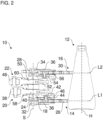
- the Figures 1 and 2 show a clamping device 10 in different views.
- the clamping device 10 holds a container 12.
- the container 12 preferably has a container body with different outer circumferences along its length or height.
- the container 12 can preferably be designed as a so-called contour container.
- the container 12 can nevertheless be held securely by the clamping device 10, as described below by way of example.
- the clamping device 10 has a first clamp arm pair 14 and a second clamp arm pair 16.
- the clamping device 10 can optionally have a clamp carrier 18, a first actuating device 20 and/or a second actuating device 22.
- the clamping device 10 is designed as a double clamping device with the two clamping arm pairs 14, 16.
- the clamping device it is also possible for the clamping device to have additional clamping arm pairs (not shown).
- the clamping device 10 can be designed as a multiple clamping device with several clamping arm pairs 14, 16.
- the first clamp arm pair 14 can have two first clamp arms 24, 26.
- the second clamp arm pair 16 can have two second clamp arms 28, 30.
- the clamp arms 24 and 26 (or 28 and 30) can be formed separately, as shown in the Figures 1 and 2 It is possible that the clamp arms 24 and 26 (or 28 and 30) are formed integrally with one another.
- the second pair of clamp arms 16 can be designed to be substantially identical in construction and/or functionally identical to the first pair of clamp arms 14.
- the first pair of clamp arms 14 and the second pair of clamp arms 16 are designed to be substantially mirror-symmetrical with respect to a central longitudinal plane of the clamping device 10 or with respect to a horizontal plane (in the assembled state).
- the central longitudinal plane divides the clamping device 10 at half height and runs parallel to the longitudinal axes L1, L2 of the pairs of clamp arms 14, 16.
- the clamp arm pairs 14, 16 are each pivotably mounted.
- the pivotable mounting is preferably arranged at one end of the clamp arm pairs 14, 16 opposite the container 12 or the free ends of the clamp arm pairs 14, 16.
- the clamp arm pairs 14, 16 can preferably be pivotable coaxially to one another or can be pivotable about a common pivot axis S.
- first clamp arms 24, 26 can preferably be pivoted in opposite directions to one another.
- the second clamp arms 28, 30 can be pivoted in opposite directions to one another.
- the first clamp arms 24, 26 can be pivoted towards one another until they rest against the container 12, and the second clamp arms 28, 30 can be pivoted towards one another until they rest against the container 12.
- the first clamp arms 24, 26 can be pivoted away from one another and the second clamp arms 28, 30 can be pivoted away from one another.
- the first and second pairs of clamp arms 14, 16 are arranged to hold the same container 12 at the same time.
- the first and second pairs of clamp arms 14, 16 are arranged vertically offset from one another, for example, with respect to a vertical axis H of the container 12.
- the second pair of clamp arms 16 (the two second clamp arms 28, 30) is arranged above the first pair of clamp arms 14 (the two first clamp arms 24, 26), as shown in the Figures 1 and 2 is shown, or vice versa.
- the first pair of clamp arms 14 can hold the container 12 at a first outer peripheral section or casing section 12A.
- the second pair of clamp arms 16 can hold the container 12 at a second outer peripheral section or casing section 12B.
- the outer peripheral sections 12A, 12B are preferably each circumferential or self-contained.
- the outer peripheral sections 12A and 12B are arranged offset from one another with respect to the vertical axis H of the container 12. For example, the second outer peripheral section 12B is arranged above the first outer peripheral section 12A, as shown in the Figures 1 and 2 is shown, or vice versa.
- the outer peripheral sections 12A and 12B can differ from one another in terms of shape and/or size or length.
- the shape of the outer peripheral sections 12A and 12B is the same, namely circular in terms of a cross section or frustoconical in terms of the vertical axis H.
- the outer peripheral sections 12A and 12B differ in size.
- the second outer peripheral section 12B has a smaller circumference and a smaller diameter than the first outer peripheral section 12A.
- the container 12 can be held at the front or the container 12 facing sections of the clamp arm pairs 14, 16.
- the container 12 can be held between the free ends of the first clamp arms 24, 26 and between the free ends of the second clamp arms 28, 30.
- the first clamp arms 24, 26 and the second clamp arms 28, 30 can grip the container 12 at their free ends.
- the first clamp arms 24, 26 and the second clamp arms 28, 30 can grip the container 12 between their free ends by applying a Clamp holding force.
- the holding force can be caused, for example, by a pre-tension acting on the first pair of clamp arms 14 and a pre-tension acting on the second pair of clamp arms 16.
- the two clamp arm pairs 14, 16 can be pivoted independently or decoupled from one another.
- the first clamp arm pair 14 can be pivoted without the second clamp arm pair 16 pivoting along with it, and vice versa.
- a pivoting movement of the first clamp arm pair 14 against the second outer peripheral section 12B does not influence a pivoting movement of the first clamp arm pair 14 against the first outer peripheral section 12A, and vice versa.
- the pivoting movement of the second clamp arm pair 16 can, for example, continue while the first clamp arm pair 14 is already resting against the first outer peripheral section 12A, and vice versa (e.g. depending on a shape and/or size of the outer peripheral sections 12A, 12B).
- the clamp arm pairs 14, 16 can begin the pivoting movements simultaneously (e.g.
- the clamp arm pairs 14, 16 are no longer actuated) and/or end them one after the other (e.g. at the time of contact with the container 12), preferably under the effect of a pre-tension of the clamp arm pairs 14 and 16.
- the first clamp arms 24, 26 pivot towards one another.
- the second clamp arms 28, 30 pivot towards one another.
- a release pivoting movement of the second clamp arm pair 16 away from the second outer peripheral portion 12B does not affect a release pivoting movement of the first clamp arm pair 14 away from the first outer peripheral portion 12A, and vice versa.
- the release pivoting movement of the first clamp arm pair 14 can, for example, begin before the release pivoting movement of the second clamp arm pair 16 begins, and vice versa (e.g. depending on a shape and/or size of the outer peripheral portions 12A, 12B).
- the clamp arm pairs 14, 16 can end the release pivoting movements simultaneously, preferably under the effect of an actuation of the clamp arm pairs 14 and 16.
- the first clamp arms 24, 26 pivot away from one another.
- the second clamp arms 28, 30 pivot away from one another.
- the clamp arm pairs 14, 16 can each extend along a longitudinal axis L1 or L2.
- the longitudinal axes L1, L2 can run essentially parallel to one another.
- the longitudinal axes L1, L2 can run essentially perpendicular to the vertical axis H.
- the longitudinal axes L1, L2 can run essentially perpendicular to the pivot axis S. In the assembled state, the longitudinal axes L1, L2 can run essentially parallel to a horizontal plane.
- the clamp arm pairs 14, 16 can be pivotally mounted on the clamp carrier 18.
- the clamp arm pairs 14, 16 can be pivotally mounted on the clamp carrier 18 on opposite sides of the clamp carrier 18.
- the clamp carrier 18 can be arranged between the clamp arm pairs 14, 16, preferably with respect to a vertical axis of the clamping device 10.
- the clamp carrier 18 can carry the clamp arm pairs 14, 16.
- the clamp carrier 18 is preferably designed in block form.
- the clamp arm carrier preferably extends longitudinally along the pivot axis S and/or parallel to the vertical axis H.
- the clamp arm pairs 14, 16 can each be pivotally mounted by means of a preferably elongated pivot pin 32, 34 of the clamp carrier 18.
- the clamp arms 24, 26, 28, 30 can each have a through hole, e.g. at an end of the respective clamp arm 24, 26, 28, 30 opposite the free end.
- the pivot pins 32, 34 can extend through the through holes. It is possible for sliding bushes to be arranged between the pivot pins 32, 34 and the through holes.
- the pivot pins 32, 34 can extend coaxially to the pivot axis S.
- the pivot pins 32, 34 can extend parallel to the vertical axis H.
- the pivot pins 32, 34 can be arranged on opposite sides of the clamp carrier 18.
- the pivot pin 34 can be arranged on an upper side of the clamp carrier 18.
- the pivot pin 32 can be arranged on an underside of the clamp carrier 18.
- the first clamp arms 24, 26 can be placed one above the other on the pivot pin 32.
- the second clamp arms 28, 30 can be placed one above the other on the pivot pin 34.
- the first clamp arms 24, 26 can be secured axially on the pivot pin 32.
- the second clamp arms 28, 30 can be secured axially on the pivot pin 34.
- the respective axial securing can be carried out, for example, by means of a screw head of a screw that is screwed into a (e.g. central) hole in the pivot pin 32, 34, preferably coaxially to the pivot axis S.
- the clamp arm pairs 14, 16 Adjacent to the pivotable mounting to the clamp carrier 18, the clamp arm pairs 14, 16 can be reinforced. In detail, a material thickness of the clamp arms 24, 26, 28, 30 adjacent to the pivotable mounting can be increased.
- the clamp arms 24, 26, 28, 30 can, for example, have reinforcing ribs 36 adjacent to the pivotable mounting.
- the reinforcing ribs 36 can, for example, be designed as wall elements on an upper side and/or a lower side of the clamp arms 24, 26, 28, 30.
- the wall elements can be ring-shaped or circumferential structures.
- the reinforcing ribs 36 can be arranged in the section of the clamp arms 24, 26, 28, 30 that is opposite the free ends of the clamp arms 24, 26, 28, 30.
- the reinforcing ribs 36 can taper towards the free ends of the clamp arms 24, 26, 28, 30.
- clamp arms 24 and 26 as well as 28 and 30 can have stops facing each other in their middle sections with respect to the longitudinal axes L1 and L2.
- the clamp arms 24 and 26 as well as 28 and 30 can rest against each other on the stops in the closed position when they are not holding a container 12.
- the clamp arm pairs 14, 16 can be pivoted by the actuating devices 20, 22 about the pivot pins 32, 34 or the pivot axis S.
- the actuating devices 20, 22 can preferably each be designed as roller controls.
- the actuating devices 20, 22 can preferably pivot the clamp arm pairs 14, 16 to release the container 12 for opening.
- the actuating devices 20, 22 are preferably of identical construction and/or function.
- the first actuating device 20 and the second actuating device 22 are essentially mirror-symmetrical with respect to the central longitudinal plane of the clamping device 10 or with respect to a horizontal plane (in the assembled state).
- the actuating devices 20, 22 can be arranged one above the other.
- the actuating devices 20, 22 can be arranged between the first clamp arm pair 14 and the second clamp arm pair 16, preferably with respect to a vertical axis of the clamping device 10.
- the first actuating device 20 can be arranged partially on an upper side of the first clamp arm pair 14.
- the second actuating device 22 can be arranged partially on an underside of the second clamp arm pair 16.
- the actuating devices 20, 22 can extend substantially parallel to the longitudinal axes L1, L2 of the clamp arm pairs 14, 16.
- the actuating devices 20, 22 can be carried by the clamp carrier 18.
- the actuating devices 20, 22 can extend through the clamp carrier 18, preferably from a rear side or a side of the clamp carrier 18 facing away from the container 12 to a front side or a side of the clamp carrier 18 facing the container 12.
- the actuating devices 20, 22 are themselves decoupled from each other so that they can move independently of each other.
- the first actuating device 20 can move without the second actuating device 22 moving, and vice versa.
- the first actuating device 20 can be connected to the first clamp arms 24, 26 in a section between the free ends and the pivot bearing of the first clamp arms 24, 26, preferably in middle sections of the first clamp arms 24, 26 with respect to the longitudinal axis L1.
- the second actuating device 22 can be connected to the second clamp arms 28, 30 in a section between the free ends and the pivot bearing of the second clamp arms 28, 30, preferably in middle sections of the second clamp arms 28, 30 with respect to the longitudinal axis L2.
- the first actuating device 20 can preferably have an input element 38, a transmission element 40, a coupling element 42 and two pivot arms 44, 46. It is possible that the components 38, 40, 42, 44, 46 are at least partially integrated into one another.
- the second actuating device 22 can be constructed and function like the first actuating device 20 with an input element 48, a transmission element 50, a coupling element 52 and two pivot arms 54, 56. The following detailed explanations of the first actuating device 20 can therefore, mutatis mutandis, apply accordingly to the second actuating device 22.
- the input element 38 is carried on the transmission element 40, preferably at the end.
- the input element 38 can be arranged on a side of the clamp carrier 18 facing away from the container 12 or on a rear side of the clamp device 10 or the clamp carrier 18.
- the input element 38 can receive a mechanical input.
- the input element can, for example, be designed as a rotatable roller, as in Figure 1 and 2 is shown, or be designed as a sliding shoe.
- the input element 38 can be acted upon by a guide curve or control curve, for example.
- the input element 38 can transmit the received input to the transmission element 40.
- the transmission element 40 is slidably mounted in the clamp carrier 18, preferably in a sliding bush.
- the transmission element 40 can be elongated, preferably rod-shaped.
- the transmission element 40 can be displaced in response to the input, preferably parallel to the longitudinal axes L1, L2 and/or perpendicular to the pivot axis S.
- the transmission element 40 carries the coupling element 42, preferably at an end opposite the input element 38.
- the coupling element 42 is attached to the transmission element 40, preferably on the front side.
- the coupling element 42 can be attached to the transmission element 40 by means of a screw. If the transmission element 40 is moved, the coupling element 42 The coupling element 42 couples the transmission element 40 with the swivel arms 44, 46.
- the pivot arm 44 connects the first clamp arm 24 to the coupling element 42.
- the pivot arm 44 is pivotally connected to the coupling element 42 at one end, e.g. by means of a bolt or pivot pin.
- the pivot arm 44 is pivotally connected to the clamp arm 24 at an opposite end, e.g. by means of a bolt or pivot pin.
- the pivot arm 46 connects the first clamp arm 26 to the coupling element 42.
- the pivot arm 46 is pivotally connected to the coupling element 42 at one end, e.g. by means of a bolt or pivot pin.
- the pivot arm 46 is pivotally connected to the first clamp arm 26 at an opposite end, e.g. by means of a bolt or pivot pin.
- the pivot arms 44, 46 are preferably arranged in a V-shape and/or one above the other (e.g. with respect to the vertical axis).
- the pivot arms 44, 46 are preferably pivotable coaxially with respect to the coupling element 42.
- parallel pivot axes for the pivot arms 44, 46 with respect to the coupling element 42 are also possible, for example.
- the pivot arms 44, 46 are preferably arranged between the coupling element 42 or the transmission element 40 and the first pair of clamp arms 14 with respect to a vertical axis of the clamping device 10.
- displacement of the input member 48 toward the container 12 causes displacement of the transmission member 40 toward the container 12.
- displacement of the transmission member 40 toward the container 12 causes displacement of the coupling member 42 toward the container 12.
- Displacement of the coupling member 42 toward the container 12 causes displacement of the ends of the pivot arms 44, 46 pivotally connected to the coupling element 42 toward the container 12.
- Displacement of the ends of the pivot arms 44, 46 pivotally connected to the coupling element 42 causes pivoting of the pivot arms 44, 46 at those ends since the pivot arms 44, 46 are supported on the first clamp arms 24, 26.
- the pivoting of the pivot arms 44, 46 causes a pivoting of the first clamp arms 24, 26, preferably a pivoting or opening of the first clamp arms 24, 26 to release the container 12.
- the clamp arm pairs 14, 16 can be subjected to a pre-tension towards closing or pivoting in.
- the clamping device 10 can have a first pre-tensioning element 58 for the first clamp arm pair 14 and a second pre-tensioning element 60 for the second clamp arm pair 16.
- the prestressing elements 58, 60 can be arranged and designed separately from the clamp arm pairs 14, 16, as in Figure 1 and 2 It is possible that the pre-tensioning elements 58, 60 are arranged directly on the clamp arm pairs 14, 16 and/or are formed integrally with the respective clamp arm pair 14 or 16.
- the pre-tensioning elements can be substantially U-shaped and/or can encompass the respective clamp arm pair 13 or 16 in a horizontal plane.
- the pre-tensioning elements 58, 60 can be arranged one above the other.
- the pre-tensioning elements 58, 60 can extend parallel to one another and/or parallel to the longitudinal axes L1, L2.
- the pre-tensioning elements 58, 60 can be arranged on a side of the clamp carrier 18 facing away from the container 12.
- the pre-tensioning elements 58, 60 can be supported on the clamp carrier 18, preferably on a side of the clamp carrier 18 facing away from the container 12.
- the pre-tensioning element 58 can be supported on the transmission element 40, preferably on an end section of the transmission element 40 carrying the input element 38.
- the pre-tensioning element 60 can be supported on the transmission element 50, preferably on an end section of the transmission element 50 carrying the input element 48.
- the transmission element 40 can extend through the preloading element 58 or the preloading element 58 can surround a portion of the transmission element 40.
- the transmission element 50 can extend through the preloading element 60 or the preloading element 60 can surround a portion of the transmission element 50.
- the preloading elements 58, 60 are designed as coil springs.
- the pre-tensioning elements 58, 60 can pre-tension the actuating devices 20, 22 in the direction away from the container 12 to close the clamp arm pairs 14, 16.
- the pre-tensioning elements 58 and 60 can pre-tension the transmission elements 40 and 50 in the direction away from the container 12.
- the clamp arms 24, 26 and 28, 30 are pivoted or pivoted towards each other.
- a holding force can be applied to the container 12 so that the container 12 can be held force-fittingly between the clamp arms 24, 26 and 28, 30.
- the preload caused by the preload elements 58, 60 for opening the clamp arm pairs 14 and 16 can be overcome.
- the clamping device 10 can have a fastening device 62.
- the fastening device 62 is designed to fasten the clamping device 10 to a transport device, e.g. a transport carousel, e.g. by means of a screw connection.
- the fastening device 62 can have at least one positioning element.
- the positioning element can position the clamping device 10 correctly on the transport device when it is fastened to the transport device.
- the positioning element can be designed as a positioning pin, for example.
- the fastening device 62 can be fastened to the clamp carrier 18, e.g. on a rear side, top side and/or bottom side of the clamp carrier 18.
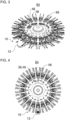
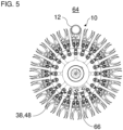
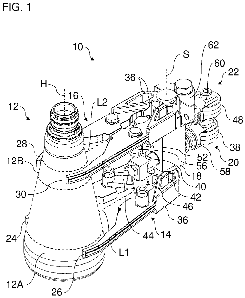
- FIGS. 3 to 5 show different views of a transport device 64 with several clamping devices 10. For the sake of clarity, only one container 12 is shown. The clamping devices 10 are nevertheless all shown as if they were each carrying a container 12.
- the transport device 64 is designed as a rotatable transport carousel.
- the clamping devices 10 are arranged, preferably evenly, around a circumference of the transport device 64.
- the transport device 64 can be designed as a so-called clamping star. Due to the double-decker nature of the clamping devices 10, the clamping star is designed as a double-decker clamping star.
- the transport device 64 has a guide contour 66.
- the input elements 38, 48 can follow the common guide contour 66.
- the temporary operative connection between the guide contour 66 and the clamp arm pairs 14 and 16 by means of the actuating devices 20, 22 causes the clamp arm pairs 14, 16 to open or pivot open.
- the container 12 is released.
- the input element 48 would first come into contact with the guide contour 66, since it protrudes further to the rear in a direction parallel to the longitudinal axes L1, L2 than the input element 38.
- the input element 38 comes into contact with the guide contour 66.
- the first pair of clamp arms 14 begins to open, while the second pair of clamp arms 16 opens further. The contact can preferably take place at a time when the pairs of clamp arms 14, 16 are equally open (closed).
- the invention is not limited to the preferred embodiments described above. Rather, a large number of variants and modifications are possible which also make use of the inventive concept and therefore fall within the scope of protection.
- the invention also claims protection for the subject matter and the features of the subclaims independently of the claims referred to.
- the individual features of independent claim 1 are each disclosed independently of one another.
- the features of the subclaims are also disclosed independently of all features of independent claim 1 and, for example, independently of the features relating to the presence and/or configuration of the first pair of clamp arms and/or the second pair of clamp arms of independent claim 1.
Landscapes
- Engineering & Computer Science (AREA)
- Mechanical Engineering (AREA)
- Specific Conveyance Elements (AREA)
- Supplying Of Containers To The Packaging Station (AREA)
- Filling Of Jars Or Cans And Processes For Cleaning And Sealing Jars (AREA)
- Load-Engaging Elements For Cranes (AREA)
Abstract
Die Erfindung betrifft u.a. eine Klammervorrichtung (10) zum Halten eines Behälters (12) für eine Behälterbehandlungsanlage. Die Klammervorrichtung (10) weist ein erstes Klammerarmpaar (14) und ein zweites Klammerarmpaar (16) auf, die zum gleichzeitigen Halten des Behälters (12) übereinander angeordnet sind, und die voneinander unabhängig schwenkbar sind, vorzugsweise koaxial. Vorteilhaft ermöglicht die Klammervorrichtung (10) das Halten des Behälters (12) an unterschiedlichen Außenformen und/oder Außenabmessungen des Behälters (12), wodurch die Prozesssicherheit und die Produktqualität verbessert werden kann.
Description
Die Erfindung betrifft eine Klammervorrichtung zum Halten eines Behälters und ein Verfahren zum Transportieren eines Behälters.The invention relates to a clamping device for holding a container and a method for transporting a container.
In Behälterbehandlungsanlagen zum Herstellen, Reinigen, Füllen, Verschließen usw. von Behältern können Behälter mittels Greifer- bzw. Klammervorrichtungen gehalten und durch die Anlage transportiert werden.In container treatment plants for manufacturing, cleaning, filling, closing, etc. containers, containers can be held and transported through the plant using gripper or clamp devices.
Beispielsweise offenbart die
Mit herkömmlichen Lösungen können keine unterschiedlichen Durchmesser an Behältern (z. B. Flaschen) gegriffen werden. Eingezogene, bauchige, konische etc. Behälter können nur unter großem Aufwand oder gar nicht von Multigarnituren im nicht-zylindrischen Bereich gehalten werden. Konturierte Flaschen werden folglich sehr weit unten gegriffen oder bewusste Fehlgriffe werden in Kauf genommen, was große Auswirkungen auf Produktqualität und Prozesssicherheit hat.Conventional solutions cannot grip containers of different diameters (e.g. bottles). Recessed, bulbous, conical, etc. containers can only be held with great effort or not at all by multi-sets in the non-cylindrical area. Contoured bottles are therefore gripped very low or deliberate incorrect grips are accepted, which has a major impact on product quality and process reliability.
Der Erfindung liegt die Aufgabe zu Grunde, eine verbesserte Technik zum Halten von Behältern zu schaffen. Bevorzugt sollen mit der Technik auch Behälter prozesssicher und beschädigungsfrei gehalten werden können, deren Mantelfläche unterschiedlich geformte und/oder unterschiedlich große Abschnitte aufweist.The invention is based on the object of creating an improved technology for holding containers. Preferably, the technology should also be able to hold containers in a process-safe and damage-free manner, the outer surface of which has differently shaped and/or differently sized sections.
Die Aufgabe wird gelöst durch die Merkmale des unabhängigen Anspruchs 1. Vorteilhafte Weiterbildungen sind in den abhängigen Ansprüchen und der Beschreibung angegeben.The problem is solved by the features of independent claim 1. Advantageous further developments are specified in the dependent claims and the description.
Ein Aspekt betrifft eine Klammervorrichtung (z. B. Doppel-Klammervorrichtung, Doppelstock-Klammervorrichtung oder Mehrfach-Klammervorrichtung) zum Halten eines Behälters für eine Behälterbehandlungsanlage (z. B. zum Herstellen, Reinigen, Prüfen, Abfüllen, Verschließen, Etikettieren, Bedrucken und/oder Verpacken von Behältern für flüssige Medien, vorzugsweise Getränke oder flüssige Nahrungsmittel). Die Klammervorrichtung weist ein erstes (z. B. unteres oder oberes) Klammerarmpaar und ein zweites (z. B. oberes oder unteres) Klammerarmpaar auf, die zum gleichzeitigen Halten des Behälters (z. B. direkt) übereinander angeordnet sind, und die voneinander unabhängig (z. B. entkoppelt) schwenkbar sind (z. B. zwischen einer Öffnungsstellung und einer Schließstellung), vorzugsweise koaxial (und/oder um eine, vorzugsweise gemeinsame, Schwenkachse).One aspect relates to a clamping device (e.g. double clamping device, double-deck clamping device or multiple clamping device) for holding a container for a container treatment system (e.g. for producing, cleaning, testing, filling, closing, labeling, printing and/or packaging containers for liquid media, preferably drinks or liquid foodstuffs). The clamping device has a first (e.g. lower or upper) pair of clamping arms and a second (e.g. upper or lower) pair of clamping arms, which are arranged one above the other (e.g. directly) to hold the container at the same time, and which can be pivoted independently of one another (e.g. decoupled) (e.g. between an open position and a closed position), preferably coaxially (and/or about a, preferably common, pivot axis).
Vorteilhaft weisen die beiden Klammerarmpaare aufgrund der voneinander unabhängigen Verschwenkbarkeit einen zusätzlichen Freiheitsgrad gegenüber herkömmlichen Lösungen auf. Vorteilhaft ermöglicht die Klammervorrichtung das Halten eines Behälters an unterschiedlichen Außenformen und/oder Außenabmessungen des Behälters. Eine Anzahl von Fehlgriffen kann auch bei aufwendiger Formgebung des Behälters verringert werden. Dadurch kann letztlich eine höhere Produktqualität und eine größere Prozesssicherheit gewährleistet werden. Insgesamt kann eine erhöhte Flexibilität hinsichtlich unterschiedlicher Formen und Größen von Behältern, die von der Klammervorrichtung gehalten und somit in der Behälterbehandlungsanlage verarbeitet werden können, erreicht werden. Die Lösung erlaubt zudem das Handhaben von Behältern mit "normalen" Behälterformen (zum Beispiel mit zylindrischem Behälterrumpf). Damit kann beispielsweise ein schneller Formatwechsel zwischen zylindrischen Behältern und Konturbehältern erfolgen, ohne dass die Klammervorrichtungen an der Transportvorrichtung gewechselt werden müssen. Nachfolgend sind besonders bevorzugte Ausführungsbeispiele beschrieben, mit denen vorteilhaft die genannten Vorteile besonders wirkungsvoll erreicht werden können.The two pairs of clamp arms advantageously have an additional degree of freedom compared to conventional solutions due to the independent pivoting capability of each other. The clamping device advantageously enables a container to be held on different external shapes and/or external dimensions of the container. The number of incorrect grips can be reduced even with complex container shapes. This ultimately ensures higher product quality and greater process reliability. Overall, increased flexibility can be achieved with regard to different shapes and sizes of containers that can be held by the clamping device and thus processed in the container treatment system. The solution also allows containers with "normal" container shapes (for example with a cylindrical container body) to be handled. This means that, for example, a quick format change between cylindrical containers and contour containers can be carried out without having to change the clamping devices on the transport device. Particularly preferred embodiments are described below, with which the advantages mentioned can be achieved particularly effectively.
Beispielsweise können die Behälter als Flaschen, Dosen, Kanister, Kartons, Flakons usw. ausgeführt sein. Beispielsweise können die Behälter eine eingezogene, bauchige, konische, sich abschnittsweise verjüngende, sich abschnittsweise erweiternde oder allgemein konturierte (z. B. Mantel bzw. Außenumfangs-) Form aufweisen.For example, the containers can be designed as bottles, cans, canisters, cartons, flacons, etc. For example, the containers can have a drawn-in, bulbous, conical, sectionally tapering, sectionally widening or generally contoured (e.g. jacket or outer circumference) shape.
Bevorzugt kann der Behälter einen ersten Außenumfangsabschnitt und einen zweiten Außenumfangsabschnitt aufweisen, die bezüglich einer Hochachse des Behälters voneinander versetzt sind und die sich in einer Größe (z. B. Querschnittsgröße oder Durchmesser) und/oder einer Form voneinander unterscheiden. Beispielsweise kann der Behälter von dem ersten Klammerarmpaar an dem ersten Außenumfangsabschnitt haltbar oder gehalten sein, und der Behälter kann von dem zweiten Klammerarmpaar an dem zweiten Außenumfangsabschnitt haltbar oder gehalten sein.Preferably, the container may have a first outer peripheral portion and a second outer peripheral portion that are offset from each other with respect to a vertical axis of the container and that differ from each other in a size (e.g. cross-sectional size or diameter) and/or a shape. For example, the container may be holdable or retained by the first pair of clamp arms at the first outer peripheral portion, and the container may be holdable or retained by the second pair of clamp arms at the second outer peripheral portion.
Vorzugsweise kann sich das erste Klammerarmpaar in einer ersten Horizontalebene erstrecken, und das zweite Klammerarmpaar kann sich in einer zweiten Horizontalebene, die von der ersten Horizontalebene beabstandet ist, erstrecken.Preferably, the first pair of clamp arms may extend in a first horizontal plane and the second pair of clamp arms may extend in a second horizontal plane spaced from the first horizontal plane.
In einem Ausführungsbeispiel weist das erste Klammerarmpaar zwei erste, vorzugsweise (z. B. mittels einer ersten Betätigungseinrichtung) miteinander gekoppelte, Klammerarme zum Anlegen an den Behälter auf, die gegensinnig zueinander schwenkbar sind (zum Beispiel um einen Drehzapfen der Klammervorrichtung). Alternativ oder zusätzlich weist das zweite Klammerarmpaar zwei zweite, vorzugsweise (z. B. mittels einer zweiten Betätigungseinrichtung) miteinander gekoppelte, Klammerarme zum Anlegen an den Behälter auf, die gegensinnig zueinander und unabhängig von den zwei ersten Klammerarmen schwenkbar sind (zum Beispiel um einen weiteren Drehzapfen der Klammervorrichtung), vorzugsweise koaxial zu den zwei ersten Klammerarmen.In one embodiment, the first pair of clamp arms has two first clamp arms, preferably coupled to one another (e.g. by means of a first actuating device), for applying to the container, which can be pivoted in opposite directions to one another (for example about a pivot pin of the clamping device). Alternatively or additionally, the second pair of clamp arms has two second clamp arms, preferably coupled to one another (e.g. by means of a second actuating device), for applying to the container, which can be pivoted in opposite directions to one another and independently of the two first clamp arms (for example about another pivot pin of the clamping device), preferably coaxially to the two first clamp arms.
Es ist möglich, dass die zwei ersten Klammerarme separat voneinander ausgebildet sind oder integral-einstückig miteinander ausgebildet sind. Alternativ oder zusätzlich können die zwei zweiten Klammerarme separat voneinander ausgebildet sein oder integral-einstückig miteinander ausgebildet sein.It is possible that the two first clamp arms are formed separately from one another or are formed integrally with one another. Alternatively or additionally, the two second clamp arms can be formed separately from one another or are formed integrally with one another.
In einem Ausführungsbeispiel sind das erste Klammerarmpaar und das zweite Klammerarmpaar derart unabhängig voneinander schwenkbar, dass der Behälter beim gleichzeitigen Halten durch das erste Klammerarmpaar und das zweite Klammerarmpaar an unterschiedlich großen und/oder unterschiedlichen geformten Außenumfangsabschnitten des Behälters haltbar ist.In one embodiment, the first pair of clamp arms and the second pair of clamp arms are pivotable independently of one another such that the container can be held on different sized and/or differently shaped outer peripheral portions of the container when simultaneously held by the first pair of clamp arms and the second pair of clamp arms.
In einem weiteren Ausführungsbeispiel sind das erste Klammerarmpaar und das zweite Klammerarmpaar derart unabhängig voneinander schwenkbar, dass ein, vorzugsweise mittels Vorspannung bewirktes, Einschwenken (bzw. Schließen) des ersten Klammerarmpaares bis zur Anlage an den Behälter fortgesetzt wird, auch wenn ein, vorzugsweise mittels Vorspannung bewirktes, Einschwenken des zweiten Klammerarmpaares durch Anlage an den Behälter bereits endet.In a further embodiment, the first pair of clamp arms and the second pair of clamp arms can be pivoted independently of one another in such a way that a pivoting in (or closing) of the first pair of clamp arms, preferably brought about by pre-tensioning, is continued until it comes into contact with the container, even if a pivoting in of the second pair of clamp arms, preferably brought about by pre-tensioning, has already ended by coming into contact with the container.
In einem weiteren Ausführungsbeispiel sind das erste Klammerarmpaar und das zweite Klammerarmpaar derart unabhängig voneinander schwenkbar, dass ein, vorzugsweise mittels Betätigung bewirktes, Aufschwenken (bzw. Öffnen) des ersten Klammerarmpaares entkoppelt von einem, vorzugsweise mittels Betätigung bewirkten, Aufschwenken des zweiten Klammerarmpaares erfolgt.In a further embodiment, the first pair of clamp arms and the second pair of clamp arms can be pivoted independently of one another in such a way that a pivoting (or opening) of the first pair of clamp arms, preferably brought about by actuation, takes place decoupled from a pivoting of the second pair of clamp arms, preferably brought about by actuation.
In einer Ausführungsform sind das erste Klammerarmpaar und das zweite Klammerarmpaar baugleich und/oder im Wesentlichen spiegelsymmetrisch bezüglich einer Horizontalebene ausgebildet.In one embodiment, the first pair of clamp arms and the second pair of clamp arms are structurally identical and/or substantially mirror-symmetrical with respect to a horizontal plane.
Vorteilhaft können somit bspw. Herstellungskosten der Klammervorrichtung reduziert und/oder eine Montage der Klammervorrichtung erleichtert werden.Advantageously, this can reduce the manufacturing costs of the clamping device and/or make assembly of the clamping device easier.
In einer weiteren Ausführungsform weist die Klammervorrichtung ferner einen, vorzugsweise im Wesentlichen blockförmigen und/oder länglichen, Klammerträger auf, der das erste Klammerarmpaar und das zweite Klammerarmpaar schwenkbar trägt (z. B. an mindestens einem Drehzapfen des Klammerträgers), vorzugsweise an einander entgegengesetzten Endbereichen des Klammerträgers (z. B. oberer Endbereich und unterer Endbereich des Klammerträgers bezüglich einer Hochachse der Klammervorrichtung). Vorteilhaft kann somit eine kompakte und stabile Klammervorrichtung geschaffen werden, die auf einfache Weise als Ganzes bspw. nur mittels des Klammerträgers an einer Transportvorrichtung zu montieren ist.In a further embodiment, the clamping device further comprises a clamp carrier, preferably substantially block-shaped and/or elongated, which pivotably supports the first clamp arm pair and the second clamp arm pair (e.g. on at least one pivot pin of the clamp carrier), preferably on opposite end regions of the clamp carrier (e.g. upper end region and lower end region of the clamp carrier with respect to a vertical axis of the clamping device). Advantageously, a compact and stable clamping device can thus be created which can be easily mounted as a whole, for example only by means of the clamp carrier, on a transport device.
In einer weiteren Ausführungsform weist die Klammervorrichtung ferner eine erste Betätigungseinrichtung, die zum Bewirken des Schwenkens (z. B. zum Öffnen) des ersten Klammerarmpaares in Wirkverbindung mit dem ersten Klammerarmpaar ist, auf. Alternativ oder zusätzlich weist die Klammervorrichtung ferner eine zweite Betätigungseinrichtung auf, die zum Bewirken des Schwenkens (z. B. zum Öffnen) des zweiten Klammerarmpaares in Wirkverbindung mit dem zweiten Klammerarmpaar ist, vorzugsweise entkoppelt von der ersten Betätigungseinrichtung. Vorteilhaft kann mittels der Betätigungseinrichtungen bspw. ein Öffnen bzw. Aufschwenken der Klammerarmpaare bewirkt werden, das im Vergleich der Klammerarmpaare bzw. der Betätigungseinrichtungen bspw. auch zeitlich verzögert beginnen kann.In a further embodiment, the clamping device further comprises a first actuating device which is operatively connected to the first clamping arm pair in order to effect the pivoting (e.g. for opening) of the first clamping arm pair. Alternatively or additionally, the clamping device further comprises a second actuating device which is operatively connected to the second clamping arm pair in order to effect the pivoting (e.g. for opening) of the second clamping arm pair, preferably decoupled from the first actuating device. The actuating devices can advantageously be used to effect, for example, an opening or pivoting of the clamping arm pairs, which can also begin with a time delay in comparison to the clamping arm pairs or the actuating devices.
In einer weiteren Ausführungsform sind die erste Betätigungseinrichtung und die zweite Betätigungseinrichtung (z. B. direkt) übereinander angeordnet und/oder baugleich und/oder im Wesentlichen spiegelsymmetrisch bezüglich einer Horizontalebene ausgebildet und/oder von einem Klammerträger der Klammervorrichtung getragen und/oder als Rollenansteuerungen ausgeführt und/oder zwischen dem ersten Klammerarmpaar und dem zweiten Klammerarmpaar angeordnet. Vorteilhaft können somit Herstellungskosten der Betätigungseinrichtungen verringert und eine Montage der Klammervorrichtung vereinfacht werden. Vorteilhaft kann ferner eine kompakte Bauform und/oder eine sichere Ansteuerung der Betätigungseinrichtungen erzielt werden.In a further embodiment, the first actuating device and the second actuating device are arranged (e.g. directly) one above the other and/or are of identical construction and/or are essentially mirror-symmetrical with respect to a horizontal plane and/or are carried by a clamp carrier of the clamping device and/or are designed as roller controls and/or are arranged between the first clamp arm pair and the second clamp arm pair. This advantageously reduces manufacturing costs for the actuating devices and simplifies assembly of the clamping device. Furthermore, a compact design and/or reliable control of the actuating devices can be achieved.
In einer weiteren Ausführungsform weist mindestens eine von der ersten Betätigungseinrichtung und der zweiten Betätigungseinrichtung zwei Schwenkarme auf. Vorzugsweise sind die zwei Schwenkarme V-förmig (bzw. scherenartig) angeordnet und/oder in Reaktion auf eine mechanische Eingabe an der jeweiligen Betätigungseinrichtung hin- und herverschiebbar und/oder an je einem Klammerarm des jeweiligen in Wirkverbindung befindlichen Klammerarmpaares schwenkbar angebracht (z. B. jeweils in einem mittleren Abschnitt der Klammerarme bzgl. einer Längsachse der Klammerarme).In a further embodiment, at least one of the first actuating device and the second actuating device has two pivot arms. Preferably, the two pivot arms are arranged in a V-shape (or scissor-like) and/or can be moved back and forth in response to a mechanical input on the respective actuating device and/or on a Clamp arm of the respective clamp arm pair in operative connection is pivotally mounted (e.g. in a middle section of the clamp arms with respect to a longitudinal axis of the clamp arms).
In einer Ausführungsvariante sind die zwei Schwenkarme, vorzugsweise koaxial, schwenkbar an einem verschiebbaren Übertragungselement angebracht. Vorzugsweise kann das Übertragungselement in einem Klammerträger der Klammervorrichtung verschiebbar gelagert sein (z. B. in einer Gleitlagerbuchse und/oder einem Durchgangsloch (z. B. zwischen einer Vorderseite und einer Rückseite des Klammerträgers)) und/oder stangenförmig sein und/oder ein Eingabeelement, vorzugsweise eine drehbare Rolle oder einen Gleitschuh, tragen (z. B. endseitig und/oder auf einer Rückseite/einer dem Behälter abgewandten Seite der Klammervorrichtung oder des Klammerträgers).In one embodiment, the two pivot arms are pivotally attached, preferably coaxially, to a displaceable transmission element. Preferably, the transmission element can be displaceably mounted in a clamp carrier of the clamping device (e.g. in a plain bearing bush and/or a through hole (e.g. between a front and a rear side of the clamp carrier)) and/or be rod-shaped and/or carry an input element, preferably a rotatable roller or a sliding shoe (e.g. at the end and/or on a rear side/a side of the clamping device or the clamp carrier facing away from the container).
In einer weiteren Ausführungsvariante weist die Klammervorrichtung ferner ein erstes Vorspannelement, vorzugsweise eine Schraubenfeder, das das erste Klammerarmpaar vorspannt, vorzugsweise zum Schließen, auf. Alternativ oder zusätzlich weist die Klammervorrichtung ferner ein zweites Vorspannelement, vorzugsweise eine Schraubenfeder, das das zweite Klammerarmpaar vorspannt, vorzugsweise zum Schließen, auf. Vorzugsweise können das erste Vorspannelement und das zweite Vorspannelement übereinander angeordnet sein und/oder sich parallel erstrecken. Vorteilhaft kann somit ein Schließen der Klammerarmpaare bewirkt werden, ohne dass hierfür eine gesonderte Betätigung notwendig wäre. Zudem kann eine Haltekraft bzw. Klemmkraft zum Halten des Behälters erzeugt werden.In a further embodiment, the clamping device further comprises a first pre-tensioning element, preferably a helical spring, which pre-tensions the first pair of clamp arms, preferably for closing. Alternatively or additionally, the clamping device further comprises a second pre-tensioning element, preferably a helical spring, which pre-tensions the second pair of clamp arms, preferably for closing. The first pre-tensioning element and the second pre-tensioning element can preferably be arranged one above the other and/or extend parallel. Advantageously, the clamping arm pairs can thus be closed without any separate actuation being necessary. In addition, a holding force or clamping force can be generated to hold the container.
Beispielsweise kann das erste und/oder zweite Vorspannelement als ein elastisches Element, z. B. eine Feder (bspw. Schraubenfeder oder U-Feder) oder ein Gummistück, oder als ein Magnet ausgeführt sein.For example, the first and/or second biasing element can be designed as an elastic element, e.g. a spring (e.g. coil spring or U-spring) or a rubber piece, or as a magnet.
In einer weiteren Ausführungsvariante stützt sich mindestens eines von dem ersten Vorspannelement und dem zweiten Vorspannelement an einem Klammerträger der Klammervorrichtung (z. B. an einer Rückseite des Klammerträgers) und/oder an einer Betätigungseinrichtung der Klammervorrichtung (z. B. an einem Übertragungselement der Betätigungseinrichtung) ab. Alternativ oder zusätzlich umgibt mindestens eines von dem ersten Vorspannelement und dem zweiten Vorspannelement einen Abschnitt (z. B. das Übertragungselement) einer Betätigungseinrichtung der Klammervorrichtung (z. B. koaxial) und/oder ist auf einer dem Behälter abgewandten Seite eines Klammerträgers der Klammervorrichtung angeordnet.In a further embodiment, at least one of the first pre-tensioning element and the second pre-tensioning element is supported on a clamp carrier of the clamping device (e.g. on a rear side of the clamp carrier) and/or on an actuating device of the clamping device (e.g. on a transmission element of the actuating device). Alternatively or additionally, at least one of the first pre-tensioning element and the second pre-tensioning element surrounds a section (e.g. the transmission element) of an actuating device of the clamping device (e.g. coaxially) and/or is arranged on a side of a clamp carrier of the clamping device facing away from the container.
Ein weiterer Aspekt betrifft eine (z. B. Linear- oder Karussell-) Transportvorrichtung, vorzugsweise einen drehbaren Klammerstern, für Behälter für eine Behälterbehandlungsanlage. Die Transportvorrichtung weist mindestens eine Klammervorrichtung wie hierin offenbart auf.A further aspect relates to a (e.g. linear or carousel) transport device, preferably a rotatable clamp star, for containers for a container treatment plant. The transport device has at least one clamp device as disclosed herein.
Es ist möglich, dass mehrere Klammervorrichtungen wie hierin offenbart umfasst sind, die bspw. verteilt um einen Umfang der Transportvorrichtung oder entlang der Transportvorrichtung angeordnet sind.It is possible that a plurality of clamping devices as disclosed herein are included, which are arranged, for example, distributed around a circumference of the transport device or along the transport device.
Beispielsweise kann die Transportvorrichtung in einer Behälterbehandlungsvorrichtung (z. B. zum Herstellen, Reinigen, Prüfen, Abfüllen, Verschließen, Etikettieren, Bedrucken und/oder Verpacken von Behältern für flüssige Medien, vorzugsweise Getränke oder flüssige Nahrungsmittel) integriert sein oder als reine Transportvorrichtung, z. B. zum Transport von Behältern von / zu einer Behälterbehandlungsvorrichtung, ausgebildet und/oder angeordnet sein.For example, the transport device can be integrated into a container treatment device (e.g. for producing, cleaning, testing, filling, closing, labeling, printing and/or packaging containers for liquid media, preferably beverages or liquid foodstuffs) or can be designed and/or arranged as a pure transport device, e.g. for transporting containers from/to a container treatment device.
In einem Ausführungsbeispiel weist die Transportvorrichtung eine gemeinsame Führungskontur auf, die dazu ausgebildet ist, in Wirkverbindung mit dem ersten Klammerarmpaar und dem zweiten Klammerarmpaar das erste Klammerarmpaar und das zweite Klammerarmpaar zu verschwenken, vorzugsweise zum Öffnen des ersten Klammerarmpaares und des zweiten Klammerarmpaares. Vorzugsweise kann somit auf einfache Weise mittels einer einzigen Führungskontur eine Betätigung des ersten und zweiten Klammerarmpaares erfolgen.In one embodiment, the transport device has a common guide contour which is designed to pivot the first pair of clamp arms and the second pair of clamp arms in operative connection with the first pair of clamp arms and the second pair of clamp arms, preferably for opening the first pair of clamp arms and the second pair of clamp arms. Preferably, the first and second pair of clamp arms can thus be actuated in a simple manner by means of a single guide contour.
Ein weiterer Aspekt betrifft ein Verfahren zum Transportieren eines Behälters, vorzugsweise mittels einer Klammervorrichtung wie hierin offenbart oder mittels einer Transportvorrichtung wie hierin offenbart. Der Behälter weist einen ersten Außenumfangsabschnitt und einen zweiten Außenumfangsabschnitt auf, die bezüglich einer Hochachse des Behälters voneinander versetzt sind, und die sich in einer Größe (z. B. Querschnittsgröße oder Durchmesser) und/oder einer Form voneinander unterscheiden. Das Verfahren weist ein voneinander unabhängiges (z. B. entkoppeltes), vorzugsweise mittels Vorspannung bewirktes, (z. B. Zu- oder Ein-) Schwenken eines ersten Klammerarmpaares und eines zweiten Klammerarmpaares (z. B. um eine, vorzugsweise gemeinsame, Schwenkachse), die übereinander angeordnet sind, bis sich das erste Klammerarmpaar an dem ersten Außenumfangsabschnitt und das zweite Klammerarmpaar an dem zweiten Außenumfangsabschnitt (z. B. jeweils beidseitig) anlegt (z. B. nacheinander), sodass der Behälter gleichzeitig von dem ersten Klammerarmpaar und dem zweiten Klammerarmpaar gehalten ist, auf. Vorzugsweise lassen sich mit dem Verfahren die gleichen Vorteile erzielen, die hierin bereits für die Klammervorrichtung beschrieben sind.A further aspect relates to a method for transporting a container, preferably by means of a clamping device as disclosed herein or by means of a transport device as disclosed herein. The container has a first outer peripheral section and a second outer peripheral section, which are offset from one another with respect to a vertical axis of the container and which differ from one another in size (e.g. cross-sectional size or diameter) and/or shape. The method comprises an independent (e.g. decoupled), preferably effected by means of prestressing, pivoting (e.g. closing or closing) of a first clamping arm pair and a second clamping arm pair (e.g. about a preferably common pivot axis), which are arranged one above the other, until the first clamping arm pair rests on the first outer peripheral section and the second clamping arm pair rests on the second outer peripheral section (e.g. on both sides in each case) (e.g. one after the other), so that the container is held simultaneously by the first clamping arm pair and the second clamping arm pair. Preferably, the method can achieve the same advantages as those already described herein for the clamping device.
Beispielsweise kann das Verfahren ferner ein Bewegen des ersten und zweiten Klammarmpaares mit dem gehaltenen Behälter zum Bewegen des Behälters aufweisen, z. B. auf einer Kreisbahn (z. B. mit Karussell wie bspw. Klammerstern) und/oder entlang einer Geraden (z. B. mit Linearförderer).For example, the method may further comprise moving the first and second pair of clamp arms with the held container to move the container, e.g. on a circular path (e.g. with a carousel such as a clamp star) and/or along a straight line (e.g. with a linear conveyor).
In einem Ausführungsbeispiel weist das Verfahren ferner ein voneinander unabhängiges (z. B. entkoppeltes) Schwenken des ersten Klammerarmpaares und des zweiten Klammerarmpaares (z. B. um eine, vorzugsweise gemeinsame, Schwenkachse) weg von dem Behälter zum Freigeben des Behälters, vorzugsweise bewirkt durch unabhängiges Betätigen des ersten Klammerarmpaares und des zweiten Klammerarmpaares, besonders bevorzugt mittels derselben Führungskontur (z. B. Steuerkurve oder Leitkurve), auf.In one embodiment, the method further comprises an independent (e.g. decoupled) pivoting of the first clamp arm pair and the second clamp arm pair (e.g. about a, preferably common, pivot axis) away from the container to release the container, preferably brought about by independent actuation of the first clamp arm pair and the second clamp arm pair, particularly preferably by means of the same guide contour (e.g. control curve or guide curve).
Die zuvor beschriebenen bevorzugten Ausführungsformen und Merkmale der Erfindung sind beliebig miteinander kombinierbar.The preferred embodiments and features of the invention described above can be combined with one another as desired.
Weitere Einzelheiten und Vorteile der Erfindung werden im Folgenden unter Bezug auf die beigefügten Zeichnungen beschrieben. Es zeigen:
- Figur 1
- eine perspektivische Ansicht einer Klammervorrichtung mit einem darin gehaltenen Behälter gemäß einem Ausführungsbeispiel der vorliegenden Offenbarung;
- Figur 2
- eine Schnittansicht durch die beispielhafte Klammervorrichtung;
- Figur 3
- eine perspektivische Ansicht einer Transportvorrichtung gemäß einem Ausführungsbeispiel der vorliegenden Offenbarung;
- Figur 4
- eine Draufsicht auf die beispielhafte Transportvorrichtung; und
- Figur 5
- eine Ansicht von unten auf die beispielhafte Transportvorrichtung.
- Figure 1
- a perspective view of a clamp device with a container held therein according to an embodiment of the present disclosure;
- Figure 2
- a sectional view through the exemplary clamping device;
- Figure 3
- a perspective view of a transport device according to an embodiment of the present disclosure;
- Figure 4
- a plan view of the exemplary transport device; and
- Figure 5
- a bottom view of the exemplary transport device.
Die in den Figuren gezeigten Ausführungsformen stimmen zumindest teilweise überein, so dass ähnliche oder identische Teile mit den gleichen Bezugszeichen versehen sind und zu deren Erläuterung auch auf die Beschreibung der anderen Ausführungsformen bzw. Figuren verwiesen wird, um Wiederholungen zu vermeiden.The embodiments shown in the figures correspond at least partially, so that similar or identical parts are provided with the same reference numerals and for their explanation reference is also made to the description of the other embodiments or figures in order to avoid repetition.
Die
Die Klammervorrichtung 10 weist ein erstes Klammerarmpaar 14 und ein zweites Klammerarmpaar 16 auf. Die Klammervorrichtung 10 kann optional einen Klammerträger 18, eine erste Betätigungseinrichtung 20 und/oder eine zweite Betätigungseinrichtung 22 aufweisen.The clamping
Vorzugsweise ist die Klammervorrichtung 10 als eine Doppel-Klammervorrichtung mit den beiden Klammerarmpaaren 14, 16 ausgeführt. Es ist allerdings auch möglich, dass die Klammervorrichtung weitere Klammerarmpaare (nicht dargestellt) aufweist. Allgemein kann die Klammervorrichtung 10 als eine Mehrfach-Klammervorrichtung mit mehreren Klammerarmpaaren 14, 16 ausgeführt sein.Preferably, the clamping
Das erste Klammerarmpaar 14 kann zwei erste Klammerarme 24, 26 aufweisen. Das zweite Klammerarmpaar 16 kann zwei zweite Klammerarme 28, 30 aufweisen. Die Klammerarme 24 und 26 (bzw. 28 und 30) können separat ausgebildet sein, wie in den
Vorzugsweise kann das zweite Klammerarmpaar 16 im Wesentlichen baugleich und/oder funktionsgleich zu dem ersten Klammerarmpaar 14 ausgeführt sein. Bevorzugt sind das erste Klammerarmpaar 14 und das zweite Klammerarmpaar 16 im Wesentlichen spiegelsymmetrisch bezüglich einer Mittellängsebene der Klammervorrichtung 10 bzw. bezüglich einer Horizontalebene (im montierten Zustand) ausgebildet. Die Mittellängsebene teilt die Klammervorrichtung 10 auf halber Höhe und verläuft parallel zu Längsachsen L1, L2 der Klammerarmpaare 14, 16.Preferably, the second pair of
Die Klammerarmpaare 14, 16 sind jeweils schwenkbar gelagert. Die schwenkbare Lagerung ist bevorzugt an einem Ende der Klammerarmpaare 14, 16 entgegengesetzt zu dem Behälter 12 bzw. den freien Enden der Klammerarmpaare 14, 16 angeordnet. Die Klammerarmpaare 14, 16 können bevorzugt koaxial zueinander verschwenkbar sein bzw. um eine gemeinsame Schwenkachse S schwenkbar sein.The clamp arm pairs 14, 16 are each pivotably mounted. The pivotable mounting is preferably arranged at one end of the clamp arm pairs 14, 16 opposite the
Im Einzelnen können die ersten Klammerarme 24, 26 bevorzugt gegensinnig zueinander schwenkbar sein. Die zweiten Klammerarme 28, 30 können gegensinnig zueinander schwenkbar sein. Zum Halten des Behälters 12 können die ersten Klammerarme 24, 26 bis zum Anlegen an den Behälter 12 zueinander geschwenkt werden, und die zweiten Klammerarme 28, 30 können bis zum Anlegen an den Behälter 12 zueinander geschwenkt werden. Zum Freigeben des Behälters 12 können die ersten Klammerarme 24, 26 voneinander weggeschwenkt werden, und die zweiten Klammerarme 28, 30 können voneinander weggeschwenkt werden.In detail, the
Das erste und zweite Klammerarmpaar 14, 16 sind zum gleichzeitigen Halten desselben Behälters 12 angeordnet. Das erste und zweite Klammerarmpaar 14, 16 sind bspw. bezüglich einer Hochachse H des Behälters 12 vertikal versetzt zueinander angeordnet. Beispielsweise ist das zweite Klammerarmpaar 16 (die zwei zweiten Klammerarme 28, 30) oberhalb von dem ersten Klammerarmpaar 14 (den zwei ersten Klammerarmen 24, 26) angeordnet, wie in den
Das erste Klammerarmpaar 14 kann den Behälter 12 an einem ersten Außenumfangsabschnitt bzw. Mantelabschnitt 12A halten. Das zweite Klammerarmpaar 16 kann den Behälter 12 an einem zweiten Außenumfangsabschnitt bzw. Mantelabschnitt 12B halten. Die Außenumfangsabschnitte 12A, 12B sind bevorzugt jeweils umlaufend bzw. in sich geschlossen. Die Außenumfangsabschnitte 12A und 12B sind bezüglich der Hochachse H des Behälters 12 versetzt zueinander angeordnet. Beispielsweise ist der zweite Außenumfangsabschnitt 12B oberhalb von dem ersten Außenumfangsabschnitt 12A angeordnet, wie in den
Die Außenumfangsabschnitte 12A und 12B können sich in einer Form und/oder einer Größe bzw. Länge voneinander unterscheiden. Im dargestellten Ausführungsbeispiel ist beispielsweise die Form der Außenumfangsabschnitte 12A und 12B jeweils gleich, nämlich kreisrund bezüglich eines Querschnitts oder kegelstumpfförmig bezüglich der Hochachse H. Die Außenumfangsabschnitte 12A und 12B unterscheiden sich in der Größe. Der zweite Außenumfangsabschnitt 12B weist einen kleineren Umfang und einen kleineren Durchmesser als der erste Außenumfangsabschnitt 12A auf.The outer
Der Behälter 12 kann jeweils an den vorderen bzw. dem Behälter 12 zugewandten Abschnitten der Klammerarmpaare 14, 16 gehalten sein. Im Einzelnen kann der Behälter 12 zwischen den freien Enden der ersten Klammerarme 24, 26 und zwischen den freien Enden der zweite Klammerarme 28, 30 gehalten sein. Die ersten Klammerarme 24, 26 und die zweiten Klammerarme 28, 30 können den Behälter 12 an ihren freien Enden umgreifen. Die ersten Klammerarme 24, 26 und die zweiten Klammerarme 28, 30 können den Behälter 12 zwischen ihren freien Enden unter Aufbringung einer Haltekraft einklemmen. Die Haltekraft kann bspw. durch eine auf das erste Klammerarmpaar 14 wirkende Vorspannung und eine auf das zweite Klammerarmpaar 16 wirkende Vorspannung bewirkt sein.The
Die beiden Klammerarmpaare 14, 16 sind unabhängig bzw. entkoppelt voneinander schwenkbar. Das erste Klammerarmpaar 14 kann verschwenkt werden, ohne dass das zweite Klammerarmpaar 16 mitschwenkt, und umgekehrt. Eine Anlageschwenkbewegung des ersten Klammerarmpaares 14 an den zweiten Außenumfangsabschnitt 12B beeinflusst eine Anlageschwenkbewegung des ersten Klammerarmpaares 14 an den ersten Außenumfangsabschnitt 12A nicht, und umgekehrt. Die Anlageschwenkbewegung des zweiten Klammerarmpaares 16 kann bspw. andauern, während das erste Klammerarmpaar 14 bereits an dem ersten Außenumfangsabschnitt 12A anliegt, und umgekehrt (z. B. abhängig von einer Form und/oder Größe der Außenumfangsabschnitte 12A, 12B). Bspw. können die Klammerarmpaare 14, 16, vorzugsweise unter Wirkung einer Vorspannung der Klammerarmpaare 14 und 16, die Anlageschwenkbewegungen gleichzeitig beginnen (z. B. bei Beenden einer Betätigung der Klammerarmpaare 14, 16) und/oder nacheinander beenden (z. B. jeweils zum Zeitpunkt der Anlage an den Behälter 12). Bei der Anlageschwenkbewegung schwenken die ersten Klammerarme 24, 26 aufeinander zu. Bei der Anlageschwenkbewegung schwenken die zweiten Klammerarme 28, 30 aufeinander zu.The two clamp arm pairs 14, 16 can be pivoted independently or decoupled from one another. The first
Eine Freigabeschwenkbewegung des zweiten Klammerarmpaares 16 weg von dem zweiten Außenumfangsabschnitt 12B beeinflusst eine Freigabeschwenkbewegung des ersten Klammerarmpaares 14 weg von dem ersten Außenumfangsabschnitt 12A nicht, und umgekehrt. Die Freigabeschwenkbewegung des ersten Klammerarmpaares 14 kann bspw. beginnen, bevor die Freigabeschwenkbewegung des zweiten Klammerarmpaares 16 beginnt, und umgekehrt (z. B. abhängig von einer Form und/oder Größe der Außenumfangsabschnitte 12A, 12B). Bspw. können die Klammerarmpaare 14, 16, vorzugsweise unter Wirkung einer Betätigung der Klammerarmpaare 14 und 16, die Freigabeschwenkbewegungen gleichzeitig beenden. Bei der Freigabeschwenkbewegung des ersten Klammerarmpaares 14 schwenken die ersten Klammerarme 24, 26 voneinander weg. Bei der Freigabeschwenkbewegung des zweiten Klammerarmpaares 16 schwenken die zweiten Klammerarme 28, 30 voneinander weg.A release pivoting movement of the second
Die Klammerarmpaare 14, 16 können sich jeweils entlang einer Längsachse L1 bzw. L2 erstrecken. Die Längsachsen L1, L2 können im Wesentlichen parallel zueinander verlaufen. Die Längsachsen L1, L2 können im Wesentlichen senkrecht zu der Hochachse H verlaufen. Die Längsachsen L1, L2 können im Wesentlichen senkrecht zu der Schwenkachse S verlaufen. Im montierten Zustand können die Längsachsen L1, L2 im Wesentlichen parallel zu einer Horizontalebene verlaufen.The clamp arm pairs 14, 16 can each extend along a longitudinal axis L1 or L2. The longitudinal axes L1, L2 can run essentially parallel to one another. The longitudinal axes L1, L2 can run essentially perpendicular to the vertical axis H. The longitudinal axes L1, L2 can run essentially perpendicular to the pivot axis S. In the assembled state, the longitudinal axes L1, L2 can run essentially parallel to a horizontal plane.
Die Klammerarmpaare 14, 16 können an dem Klammerträger 18 schwenkbar gelagert sein. Die Klammerarmpaare 14, 16 können auf entgegengesetzten Seiten des Klammerträgers 18 an dem Klammerträger 18 schwenkbar gelagert sein. Der Klammerträger 18 kann zwischen den Klammerarmpaaren 14, 16 angeordnet sein, vorzugsweise bezüglich einer Hochachse der Klammervorrichtung 10. Der Klammerträger 18 kann die Klammerarmpaare 14, 16 tragen. Der Klammerträger 18 ist vorzugsweise blockförmig ausgeführt. Der Klammerarmträger erstreckt sich vorzugsweise länglich entlang der Schwenkachse S und/oder parallel zur Hochachse H.The clamp arm pairs 14, 16 can be pivotally mounted on the
Beispielsweise können die Klammerarmpaare 14, 16 jeweils mittels eines, vorzugsweise länglichen, Drehzapfens 32, 34 des Klammerträgers 18 schwenkbar gelagert sein. Im Einzelnen können die Klammerarme 24, 26, 28, 30 jeweils ein Durchgangsloch aufweisen, z. B. an einem der jeweils freien Ende entgegengesetzten Ende des jeweiligen Klammerarms 24, 26, 28, 30. Die Drehzapfen 32, 34 können sich durch die Durchgangslöcher erstrecken. Es ist möglich, dass Gleitbuchsen zwischen den Drehzapfen 32, 34 und den Durchgangslöchern angeordnet sind.For example, the clamp arm pairs 14, 16 can each be pivotally mounted by means of a preferably elongated
Die Drehzapfen 32, 34 können sich koaxial zu der Schwenkachse S erstrecken. Die Drehzapfen 32, 34 können sich parallel zu der Hochachse H erstrecken. Der Drehzapfen 32, 34 können auf entgegengesetzten Seiten des Klammerträgers 18 angeordnet sein. Beispielsweise kann der Drehzapfen 34 auf einer Oberseite des Klammerträgers 18 angeordnet sein. Der Drehzapfen 32 kann auf einer Unterseite des Klammerträgers 18 angeordnet sein.The pivot pins 32, 34 can extend coaxially to the pivot axis S. The pivot pins 32, 34 can extend parallel to the vertical axis H. The pivot pins 32, 34 can be arranged on opposite sides of the
Die ersten Klammerarme 24, 26 können übereinander auf den Drehzapfen 32 aufgesteckt sein. Die zweiten Klammerarme 28, 30 können übereinander auf den Drehzapfen 34 aufgesteckt sein. Die ersten Klammerarme 24, 26 können axial auf dem Drehzapfen 32 gesichert sein. Die zweiten Klammerarme 28, 30 können axial auf dem Drehzapfen 34 gesichert sein. Die jeweilige axiale Sicherung kann bspw. mittels eines Schraubenkopfes einer Schraube erfolgen, die in ein (z. B. Zentral-) Loch im Drehzapfen 32, 34 eingeschraubt ist, vorzugsweise koaxial zur Schwenkachse S.The
Angrenzend an die schwenkbare Lagerung zum Klammerträger 18 können die Klammerarmpaare 14, 16 verstärkt sein. Im Einzelnen kann eine Materialstärke der Klammerarme 24, 26, 28, 30 angrenzend an die schwenkbare Lagerung vergrößert sein. Die Klammerarme 24, 26, 28, 30 können bspw. Verstärkungsrippen 36 angrenzend an die schwenkbare Lagerung aufweisen. Die Verstärkungsrippen 36 können bspw. als Wandelemente auf einer Oberseite und/oder einer Unterseite der Klammerarme 24, 26, 28, 30 ausgeführt sein. Die Wandelemente können ringförmige bzw. umlaufende Strukturen sein. Die Verstärkungsrippen 36 können im Abschnitt der Klammerarme 24, 26, 28, 30 angeordnet sein, die den freien Enden der Klammerarme 24, 26, 28, 30 entgegengesetzt sind. Die Verstärkungsrippen 36 können sich in Richtung zu den freien Enden der Klammerarme 24, 26, 28, 30 verjüngen.Adjacent to the pivotable mounting to the
Es ist möglich, dass die Klammerarme 24 und 26 sowie 28 und 30 in deren Mittelabschnitten bezüglich der Längsachsen L1 sowie L2 einander zugewandte Anschläge aufweisen. An den Anschlägen können die Klammerarme 24 und 26 sowie 28 und 30 in der Schließstellung aneinander anliegen, wenn sie keinen Behälter 12 halten.It is possible for the
Die Klammerarmpaare 14, 16 können von den Betätigungseinrichtungen 20, 22 um die Drehzapfen 32, 34 bzw. die Schwenkachse S geschwenkt werden. Die Betätigungseinrichtungen 20, 22 können vorzugsweise jeweils als Rollenansteuerungen ausgeführt sein. Bevorzugt können die Betätigungseinrichtungen 20, 22 die Klammerarmpaare 14, 16 zum Freigeben des Behälters 12 zum Öffnen schwenken.The clamp arm pairs 14, 16 can be pivoted by the
Die Betätigungseinrichtungen 20, 22 sind bevorzugt baugleich und/oder funktionsgleich ausgebildet. Bevorzugt sind die erste Betätigungseinrichtung 20 und die zweite Betätigungseinrichtung 22 im Wesentlichen spiegelsymmetrisch bezüglich der Mittellängsebene der Klammervorrichtung 10 bzw. bezüglich einer Horizontalebene (im montierten Zustand) ausgebildet.The
Die Betätigungseinrichtungen 20, 22 können übereinander angeordnet sein. Die Betätigungseinrichtungen 20, 22 können zwischen dem ersten Klammerarmpaar 14 und dem zweiten Klammerarmpaar 16 angeordnet sein, vorzugsweise bezüglich einer Hochachse der Klammervorrichtung 10. Im Einzelnen kann die erste Betätigungseinrichtung 20 teilweise auf einer Oberseite des ersten Klammerarmpaares 14 angeordnet sein. Die zweite Betätigungseinrichtung 22 kann teilweise auf einer Unterseite des zweiten Klammerarmpaares 16 angeordnet sein. Die Betätigungseinrichtungen 20, 22 können sich im Wesentlichen parallel zu den Längsachsen L1, L2 der Klammerarmpaare 14, 16 erstrecken.The
Die Betätigungseinrichtungen 20, 22 können von dem Klammerträger 18 getragen sein. Die Betätigungseinrichtungen 20, 22 können sich durch den Klammerträger 18 hindurch erstrecken, vorzugsweise von einer Rückseite bzw. einer dem Behälter 12 abgewandten Seite des Klammerträgers 18 zu einer Vorderseite bzw. einer dem Behälter 12 zugewandten Seite des Klammerträgers 18.The
Die Betätigungseinrichtungen 20, 22 sind selbst entkoppelt voneinander, sodass sie sich unabhängig voneinander bewegen können. Die erste Betätigungseinrichtung 20 kann sich bewegen, ohne dass sich die zweite Betätigungseinrichtung 22 bewegt, und umgekehrt.The
Die erste Betätigungseinrichtung 20 kann in einem Abschnitt zwischen den freien Enden und der Schwenklagerung der ersten Klammerarme 24, 26 mit den ersten Klammerarmen 24, 26 verbunden sein, vorzugsweise in Mittelabschnitten der ersten Klammerarme 24, 26 bezüglich der Längsachse L1. Die zweite Betätigungseinrichtung 22 kann in einem Abschnitt zwischen den freien Enden und der Schwenklagerung der zweiten Klammerarme 28, 30 mit den zweiten Klammerarmen 28, 30 verbunden sein, vorzugsweise in Mittelabschnitten der zweiten Klammerarme 28, 30 bezüglich der Längsachse L2.The
Die erste Betätigungseinrichtung 20 kann vorzugsweise ein Eingabeelement 38, ein Übertragungselement 40, ein Koppelelement 42 und zwei Schwenkarme 44, 46 aufweisen. Es ist möglich, dass die Komponenten 38, 40, 42, 44, 46 zumindest teilweise ineinander integriert sind. Die zweite Betätigungseinrichtung 22 kann mit einem Eingabeelement 48, einem Übertragungselement 50, einem Koppelelement 52 und zwei Schwenkarmen 54, 56 wie die erste Betätigungseinrichtung 20 aufgebaut sein und funktionieren. Die nachfolgenden Detailausführungen zu der ersten Betätigungseinrichtung 20 können somit, mutatis mutandis, entsprechend für die zweite Betätigungseinrichtung 22 gelten.The
Das Eingabeelement 38 ist an dem Übertragungselement 40 getragen, vorzugsweise endseitig. Das Eingabeelement 38 kann auf einer dem Behälter 12 abgewandten Seite des Klammerträgers 18 bzw. auf einer Rückseite der Klammervorrichtung 10 bzw. des Klammerträgers 18 angeordnet sein. Das Eingabeelement 38 kann eine mechanische Eingabe empfangen. Das Eingabeelement kann bspw. als eine drehbare Rolle, wie in
Das Übertragungselement 40 ist verschiebbar in dem Klammerträger 18 gelagert, vorzugsweise in einer Gleitbuchse. Das Übertragungselement 40 kann länglich, vorzugsweise stangenförmig, sein. Das Übertragungselement 40 kann in Reaktion auf die Eingabe verschoben werden, vorzugsweise parallel zu den Längsachsen L1, L2 und/oder senkrecht zu der Schwenkachse S. Das Übertragungselement 40 trägt das Koppelelement 42, vorzugsweise an einem dem Eingabeelement 38 entgegengesetzten Ende.The
Das Koppelelement 42 ist an dem Übertragungselement 40 angebracht, vorzugsweise stirnseitig. Beispielsweise kann das Koppelelement 42 mittels einer Schraube an dem Übertragungselement 40 angebracht sein. Wird das Übertragungselement 40 verschoben, wird das Koppelelement 42 mitverschoben. Das Koppelelement 42 koppelt das Übertragungselement 40 mit den Schwenkarmen 44, 46.The
Der Schwenkarm 44 verbindet den ersten Klammerarm 24 mit dem Koppelelement 42. Der Schwenkarm 44 ist an einem Ende schwenkbar mit dem Koppelelement 42 verbunden, z. B. mittels eines Bolzens oder Drehzapfens. Der Schwenkarm 44 ist an einem entgegengesetzten Ende schwenkbar mit dem Klammerarm 24 verbunden, z. B. mittels eines Bolzens oder Drehzapfens.The
Der Schwenkarm 46 verbindet den ersten Klammerarm 26 mit dem Koppelelement 42. Der Schwenkarm 46 ist an einem Ende schwenkbar mit dem Koppelelement 42 verbunden, z. B. mittels eines Bolzens oder Drehzapfens. Der Schwenkarm 46 ist an einem entgegengesetzten Ende schwenkbar mit dem ersten Klammerarm 26 verbunden, z. B. mittels eines Bolzens oder Drehzapfens.The
Die Schwenkarme 44, 46 sind bevorzugt V-förmig und/oder übereinander (z. B. bezüglich der Hochachse) angeordnet. Die Schwenkarme 44, 46 sind vorzugsweise koaxial bezüglich des Koppelelements 42 schwenkbar. Es sind allerdings bspw. auch parallele Schwenkachsen für die Schwenkarme 44, 46 bezüglich des Koppelelements 42 möglich. Die Schwenkarme 44, 46 sind bezüglich einer Hochachse der Klammervorrichtung 10 vorzugsweise zwischen dem Koppelelement 42 bzw. dem Übertragungselement 40 und dem ersten Klammerarmpaar 14 angeordnet.The
In Reaktion auf eine mechanische Eingabe bewirkt eine Verschiebung des Eingabeelements 48 in Richtung zu dem Behälter 12 eine Verschiebung des Übertragungselements 40 in Richtung zu dem Behälter 12. Eine Verschiebung des Übertragungselements 40 in Richtung zu dem Behälter 12 bewirkt eine Verschiebung des Koppelelements 42 in Richtung zu dem Behälter 12. Eine Verschiebung des Koppelelements 42 in Richtung zu dem Behälter 12 bewirkt eine Verschiebung der mit dem Koppelelement 42 schwenkbar verbundenen Enden der Schwenkarme 44, 46 in Richtung zu dem Behälter 12. Eine Verschiebung der schwenkbar mit dem Koppelelement 42 verbundenen Enden der Schwenkarme 44, 46 bewirkt ein Schwenken der Schwenkarme 44, 46 an diesen Enden, da die Schwenkarme 44, 46 an den ersten Klammerarmen 24, 26 abgestützt sind. Das Schwenken der Schwenkarme 44, 46 bewirkt ein Schwenken der ersten Klammerarme 24, 26, vorzugsweise ein Aufschwenken bzw. Öffnen der ersten Klammerarme 24, 26 zum Freigeben des Behälters 12.In response to a mechanical input, displacement of the
Die Klammerarmpaare 14, 16 können mit einer Vorspannung hin zum Schließen bzw. Einschwenken beaufschlagt sein. Bspw. kann die Klammervorrichtung 10 ein erstes Vorspannelement 58 für das erste Klammerarmpaar 14 und zweites Vorspannelement 60 für das zweite Klammerarmpaar 16 aufweisen.The clamp arm pairs 14, 16 can be subjected to a pre-tension towards closing or pivoting in. For example, the clamping
Die Vorspannelemente 58, 60 können separat von den Klammerarmpaaren 14, 16 angeordnet und ausgebildet sein, wie in
Die Vorspannelemente 58, 60 können übereinander angeordnet sein. Die Vorspannelemente 58, 60 können sich parallel zueinander und/oder parallel zu den Längsachsen L1, L2 erstrecken. Die Vorspannelemente 58, 60 können auf einer dem Behälter 12 abgewandten Seite des Klammerträgers 18 angeordnet sein.The
Die Vorspannelemente 58, 60 können sich an dem Klammerträger 18 abstützen, vorzugsweise an einer dem Behälter 12 abgewandten Seite des Klammerträgers 18. Das Vorspannelement 58 kann sich an dem Übertragungselement 40 abstützen, vorzugsweise an einem das Eingabeelement 38 tragenden Endabschnitt des Übertragungselements 40. Das Vorspannelement 60 kann sich an dem Übertragungselement 50 abstützen, vorzugsweise an einem das Eingabeelement 48 tragenden Endabschnitt des Übertragungselements 50.The
Das Übertragungselement 40 kann sich durch das Vorspannelement 58 hindurch erstrecken bzw. das Vorspannelement 58 kann einen Abschnitt des Übertragungselements 40 umgeben. Das Übertragungselement 50 kann sich durch das Vorspannelement 60 hindurch erstrecken bzw. das Vorspannelement 60 kann einen Abschnitt des Übertragungselements 50 umgeben. Beispielsweise sind die Vorspannelemente 58, 60 als Schraubenfedern ausgeführt.The
Beispielsweise können die Vorspannelemente 58, 60 die Betätigungseinrichtungen 20, 22 in Richtung weg von dem Behälter 12 zum Schließen der Klammerarmpaare 14, 16 vorspannen. Im Einzelnen können die Vorspannelemente 58 und 60 die Übertragungselemente 40 und 50 in Richtung weg von dem Behälter 12 vorspannen. Durch die Kopplung mit den Schwenkarmen 44, 46 und 54, 56 werden die Klammerarme 24, 26 und 28, 30 zueinander geschwenkt bzw. eingeschwenkt. Mittels der Vorspannung kann eine Haltekraft auf den Behälter 12 aufgebracht werden, sodass der Behälter 12 kraftschlüssig zwischen den Klammerarm 24, 26 und 28, 30 gehalten werden kann. Mittels der mechanischen Eingabe an den Eingabeelementen 38 und 48 kann die durch die Vorspannelemente 58, 60 bewirkte Vorspannung zum Öffnen der Klammerarmpaare 14 und 16 überwunden werden.For example, the
Die Klammervorrichtung 10 kann eine Befestigungseinrichtung 62 aufweisen. Die Befestigungseinrichtung 62 ist dazu ausgebildet, die Klammervorrichtung 10 an einer Transportvorrichtung, z. B. einem Transportkarussell, zu befestigen, z. B. mittels einer Schraubverbindung. Die Befestigungseinrichtung 62 kann mindestens ein Positionierelement aufweisen. Das Positionierelement kann die Klammervorrichtung 10 bei der Befestigung an der Transportvorrichtung korrekt an der Transportvorrichtung positionieren. Das Positionierelement kann bspw. als ein Positionierstift ausgeführt sein. Die Befestigungseinrichtung 62 kann an dem Klammerträger 18 befestigt sein, z. B. an einer Rückseite, Oberseite und/oder Unterseite des Klammerträgers 18.The clamping
Die
Die Transportvorrichtung 64 ist als ein drehbares Transportkarussell ausgeführt. Die Klammervorrichtungen 10 sind, vorzugsweise gleichmäßig, um einen Umfang der Transportvorrichtung 64 herum angeordnet. Die Transportvorrichtung 64 kann als ein sogenannter Klammerstern ausgeführt sein. Aufgrund der Doppelstöckigkeit der Klammervorrichtungen 10 ist der Klammerstern als doppelstöckiger Klammerstern ausgeführt.The
Die Transportvorrichtung 64 weist eine Führungskontur 66 auf. Die Eingabeelemente 38, 48 können der gemeinsamen Führungskontur 66 folgen. Die temporäre Wirkverbindung zwischen der Führungskontur 66 und den Klammerarmpaaren 14 und 16 mittels der Betätigungseinrichtungen 20, 22 bewirkt ein Öffnen bzw. Aufschwenken der Klammerarmpaare 14, 16. Der Behälter 12 wird freigegeben.The
Bei dem im Ausführungsbeispiel dargestellten Behälter 12, der oben schmaler als unten ist, würde das Eingabeelement 48 zuerst in Kontakt mit der Führungskontur 66 gelangen, da es in einer Richtung parallel zu den Längsachsen L1, L2 weiter nach hinten vorsteht als das Eingabeelement 38. Nachdem das Öffnen des zweiten Klammerarmpaares 16 aufgrund der Wirkverbindung zu der Führungskontur 66 mittels der zweiten Betätigungseinrichtung 22 bereits begonnen hat, gelangt das Eingabeelement 38 in Kontakt mit der Führungskontur 66. Das erste Klammerarmpaar 14 beginnt sich zu öffnen, während das zweite Klammerarmpaar 16 sich weiter öffnet. Der Kontakt kann vorzugsweise zu einem Zeitpunkt erfolgen, zu dem die Klammerarmpaare 14, 16 gleich weit geöffnet (geschlossen) sind.In the case of the
Die Erfindung ist nicht auf die vorstehend beschriebenen bevorzugten Ausführungsbeispiele beschränkt. Vielmehr ist eine Vielzahl von Varianten und Abwandlungen möglich, die ebenfalls von dem Erfindungsgedanken Gebrauch machen und deshalb in den Schutzbereich fallen. Insbesondere beansprucht die Erfindung auch Schutz für den Gegenstand und die Merkmale der Unteransprüche unabhängig von den in Bezug genommenen Ansprüchen. Insbesondere sind die einzelnen Merkmale des unabhängigen Anspruchs 1 jeweils unabhängig voneinander offenbart. Zusätzlich sind auch die Merkmale der Unteransprüche unabhängig von sämtlichen Merkmalen des unabhängigen Anspruchs 1 und beispielsweise unabhängig von den Merkmalen bezüglich des Vorhandenseins und/oder der Konfiguration des ersten Klammerarmpaares und/oder des zweiten Klammerarmpaares des unabhängigen Anspruchs 1 offenbart.The invention is not limited to the preferred embodiments described above. Rather, a large number of variants and modifications are possible which also make use of the inventive concept and therefore fall within the scope of protection. In particular, the invention also claims protection for the subject matter and the features of the subclaims independently of the claims referred to. In particular, the individual features of independent claim 1 are each disclosed independently of one another. In addition, the features of the subclaims are also disclosed independently of all features of independent claim 1 and, for example, independently of the features relating to the presence and/or configuration of the first pair of clamp arms and/or the second pair of clamp arms of independent claim 1.
- 1010
- Klammervorrichtungclamping device
- 1212
- Behältercontainer
- 12A12A
- Erster AußenumfangsabschnittFirst outer circumference section
- 12B12B
- Zweiter AußenumfangsabschnittSecond outer circumference section
- 1414
- Erstes Klammerarmpaarfirst pair of clamp arms
- 1616
- Zweites Klammerarmpaarsecond pair of clamp arms
- 1818
- Klammerträgerbracket carrier
- 2020
- Erste BetätigungseinrichtungFirst actuating device
- 2222
- Zweite BetätigungseinrichtungSecond actuating device
- 2424
- Klammerarmclamp arm
- 2626
- Klammerarmclamp arm
- 2828
- Klammerarmclamp arm
- 3030
- Klammerarmclamp arm
- 3232
- Drehzapfenpivot pin
- 3434
- Drehzapfenpivot pin
- 3636
- Verstärkungsrippereinforcing rib
- 3838
- Eingabeelementinput element
- 4040
- Übertragungselementtransmission element
- 4242
- Koppelelementcoupling element
- 4444
- Schwenkarmswivel arm
- 4646
- Schwenkarmswivel arm
- 4848
- Eingabeelementinput element
- 5050
- Übertragungselementtransmission element
- 5252
- Koppelelementcoupling element
- 5454
- Schwenkarmswivel arm
- 5656
- Schwenkarmswivel arm
- 5858
- Vorspannelementpreload element
- 6060
- Vorspannelementpreload element
- 6262
- Befestigungseinrichtungfastening device
- 6464
- Transportvorrichtungtransport device
- 6666
- Führungskontur (Steuerkurve/Leitkurve)guide contour (control curve/guide curve)
- HH
- Hochachsevertical axis
- SS
- Schwenkachseswivel axis
- L1L1
- Längsachselongitudinal axis
- L2L2
- Längsachselongitudinal axis
Claims (15)
ein erstes Klammerarmpaar (14) und ein zweites Klammerarmpaar (16), die zum gleichzeitigen Halten des Behälters (12) übereinander angeordnet sind, und die voneinander unabhängig schwenkbar sind, vorzugsweise koaxial.Clamping device (10) for holding a container (12) for a container treatment plant, comprising:
a first pair of clamp arms (14) and a second pair of clamp arms (16) which are arranged one above the other for simultaneously holding the container (12) and which are pivotable independently of one another, preferably coaxially.
das erste Klammerarmpaar (14) und das zweite Klammerarmpaar (16) baugleich und/oder im Wesentlichen spiegelsymmetrisch bezüglich einer Horizontalebene ausgebildet sind.Clamp device (10) according to one of claims 1 to 3, wherein
the first pair of clamp arms (14) and the second pair of clamp arms (16) are structurally identical and/or substantially mirror-symmetrical with respect to a horizontal plane.
einen, vorzugsweise im Wesentlichen blockförmigen und/oder länglichen, Klammerträger (18), der das erste Klammerarmpaar (14) und das zweite Klammerarmpaar (16) schwenkbar trägt, vorzugsweise an einander entgegengesetzten Endbereichen des Klammerträgers (18).Clamp device (10) according to one of the preceding claims, further comprising:
a preferably substantially block-shaped and/or elongated clamp carrier (18) which pivotably supports the first pair of clamp arms (14) and the second pair of clamp arms (16), preferably at opposite end regions of the clamp carrier (18).
die erste Betätigungseinrichtung (20) und die zweite Betätigungseinrichtung (22) übereinander angeordnet, baugleich, im Wesentlichen spiegelsymmetrisch bezüglich einer Horizontalebene ausgebildet, von einem Klammerträger (18) der Klammervorrichtung (10) getragen, als Rollenansteuerungen ausgeführt und/oder zwischen dem ersten Klammerarmpaar (14) und dem zweiten Klammerarmpaar (16) angeordnet sind.Clamp device (10) according to claim 6, wherein:
the first actuating device (20) and the second actuating device (22) are arranged one above the other, are structurally identical, are essentially mirror-symmetrical with respect to a horizontal plane, are carried by a clamp carrier (18) of the clamping device (10), are designed as roller controls and/or are arranged between the first clamp arm pair (14) and the second clamp arm pair (16).
mindestens eine von der ersten Betätigungseinrichtung (20) und der zweiten Betätigungseinrichtung (22) zwei Schwenkarme (44, 46, 54, 56) aufweist, die V-förmig angeordnet, in Reaktion auf eine mechanische Eingabe an der jeweiligen Betätigungseinrichtung (20, 22) hin- und herverschiebbar und/oder an je einem Klammerarm (24, 26, 28, 30) des jeweiligen in Wirkverbindung befindlichen Klammerarmpaares (14, 16) schwenkbar angebracht sind.A clamp device (10) according to claim 6 or claim 7, wherein:
at least one of the first actuating device (20) and the second actuating device (22) has two pivot arms (44, 46, 54, 56) which are arranged in a V-shape, can be moved back and forth in response to a mechanical input on the respective actuating device (20, 22) and/or are pivotally attached to a clamp arm (24, 26, 28, 30) of the respective clamp arm pair (14, 16) which are in operative connection.
die zwei Schwenkarme (44, 46, 54, 56), vorzugsweise koaxial, schwenkbar an einem verschiebbaren Übertragungselement (40, 50) angebracht sind, das in einem Klammerträger (18) der Klammervorrichtung (10) verschiebbar gelagert ist, stangenförmig ist und/oder ein Eingabeelement (38, 48), vorzugsweise eine drehbare Rolle oder einen Gleitschuh, trägt.Clamp device (10) according to claim 8, wherein:
the two pivot arms (44, 46, 54, 56), preferably coaxially, are pivotally attached to a displaceable transmission element (40, 50) which is displaceably mounted in a clamp carrier (18) of the clamping device (10), is rod-shaped and/or carries an input element (38, 48), preferably a rotatable roller or a sliding shoe.
mindestens eines von dem ersten Vorspannelement (58) und dem zweiten Vorspannelement (60) sich an einem Klammerträger (18) der Klammervorrichtung (10) abstützt, sich an einer Betätigungseinrichtung (20, 22) der Klammervorrichtung (10) abstützt, einen Abschnitt einer Betätigungseinrichtung (20, 22) der Klammervorrichtung (10) umgibt und/oder auf einer dem Behälter (12) abgewandten Seite eines Klammerträgers (18) der Klammervorrichtung (10) angeordnet ist.Clamp device (10) according to claim 10, wherein:
at least one of the first prestressing element (58) and the second prestressing element (60) is supported on a clamp carrier (18) of the clamping device (10), is supported on an actuating device (20, 22) of the clamping device (10), surrounds a section of an actuating device (20, 22) of the clamping device (10) and/or is arranged on a side of a clamp carrier (18) of the clamping device (10) facing away from the container (12).
mindestens eine Klammervorrichtung (10) nach einem der vorherigen Ansprüche.Transport device (64), preferably a rotatable clamp star, for containers (12) for a container treatment plant, comprising:
at least one clamping device (10) according to one of the preceding claims.
eine gemeinsame Führungskontur (66), die dazu ausgebildet ist, in Wirkverbindung mit dem ersten Klammerarmpaar (14) und dem zweiten Klammerarmpaar (16) das erste Klammerarmpaar (14) und das zweite Klammerarmpaar (16) zu verschwenken, vorzugsweise zum Öffnen des ersten Klammerarmpaares (14) und des zweiten Klammerarmpaares (16).Transport device (64) according to claim 12, further comprising:
a common guide contour (66) which is designed to pivot the first clamp arm pair (14) and the second clamp arm pair (16) in operative connection with the first clamp arm pair (14) and the second clamp arm pair (16), preferably for opening the first clamp arm pair (14) and the second clamp arm pair (16).
voneinander unabhängiges, vorzugsweise mittels Vorspannung bewirktes, Schwenken eines ersten Klammerarmpaares (14) und eines zweiten Klammerarmpaares (16), die übereinander angeordnet sind, bis sich das erste Klammerarmpaar (14) an dem ersten Außenumfangsabschnitt (12A) und das zweite Klammerarmpaar (16) an dem zweiten Außenumfangsabschnitt (12B) anlegt, sodass der Behälter (12) gleichzeitig von dem ersten Klammerarmpaar (14) und dem zweiten Klammerarmpaar (16) gehalten ist.
independent pivoting, preferably by means of pre-tensioning, of a first pair of clamp arms (14) and a second pair of clamp arms (16), which are arranged one above the other, until the first pair of clamp arms (14) rests on the first outer peripheral portion (12A) and the second pair of clamp arms (16) rests on the second outer peripheral portion (12B), so that the container (12) is held simultaneously by the first pair of clamp arms (14) and the second pair of clamp arms (16).
voneinander unabhängiges Schwenken des ersten Klammerarmpaares (14) und des zweiten Klammerarmpaares (16) weg von dem Behälter (12) zum Freigeben des Behälters (12), vorzugsweise bewirkt durch unabhängiges Betätigen des ersten Klammerarmpaares (14) und des zweiten Klammerarmpaares (16), besonders bevorzugt mittels derselben Führungskontur (66).The method of claim 14, further comprising:
independent pivoting of the first pair of clamp arms (14) and the second pair of clamp arms (16) away from the container (12) to release the container (12), preferably effected by independent actuation of the first pair of clamp arms (14) and the second pair of clamp arms (16), particularly preferably by means of the same guide contour (66).
Applications Claiming Priority (2)
| Application Number | Priority Date | Filing Date | Title |
|---|---|---|---|
| DE102021107294.8A DE102021107294A1 (en) | 2021-03-24 | 2021-03-24 | Clamping device and method for transporting a container |
| EP22163830.7A EP4067270B1 (en) | 2021-03-24 | 2022-03-23 | Clamp device and method for transporting a container |
Related Parent Applications (2)
| Application Number | Title | Priority Date | Filing Date |
|---|---|---|---|
| EP22163830.7A Division EP4067270B1 (en) | 2021-03-24 | 2022-03-23 | Clamp device and method for transporting a container |
| EP22163830.7A Division-Into EP4067270B1 (en) | 2021-03-24 | 2022-03-23 | Clamp device and method for transporting a container |
Publications (2)
| Publication Number | Publication Date |
|---|---|
| EP4477331A2 true EP4477331A2 (en) | 2024-12-18 |
| EP4477331A3 EP4477331A3 (en) | 2025-03-12 |
Family
ID=80930139
Family Applications (2)
| Application Number | Title | Priority Date | Filing Date |
|---|---|---|---|
| EP24201833.1A Pending EP4477331A3 (en) | 2021-03-24 | 2022-03-23 | Clamping device and method for transporting a container |
| EP22163830.7A Active EP4067270B1 (en) | 2021-03-24 | 2022-03-23 | Clamp device and method for transporting a container |
Family Applications After (1)
| Application Number | Title | Priority Date | Filing Date |
|---|---|---|---|
| EP22163830.7A Active EP4067270B1 (en) | 2021-03-24 | 2022-03-23 | Clamp device and method for transporting a container |
Country Status (4)
| Country | Link |
|---|---|
| US (1) | US20220306401A1 (en) |
| EP (2) | EP4477331A3 (en) |
| CN (1) | CN115123807B (en) |
| DE (1) | DE102021107294A1 (en) |
Families Citing this family (7)
| Publication number | Priority date | Publication date | Assignee | Title |
|---|---|---|---|---|
| IT202000014836A1 (en) * | 2020-06-22 | 2021-12-22 | Arol Spa | CONTAINER HANDLING DEVICE FOR CORKING INSTALLATIONS |
| USD976095S1 (en) * | 2021-05-17 | 2023-01-24 | Elesa S.P.A. | Clamp |
| DE102021129518A1 (en) | 2021-11-12 | 2023-05-17 | Krones Aktiengesellschaft | Clamping device and transport device |
| USD1101548S1 (en) * | 2022-12-05 | 2025-11-11 | Elesa S.P.A. | Clamp |
| DE102023102680A1 (en) | 2023-02-03 | 2024-08-08 | Krones Aktiengesellschaft | Container treatment plant with improved feeding |
| CN116772093A (en) * | 2023-06-06 | 2023-09-19 | 宁波大通亨利机械制造有限公司 | An automatic canning device for tanks |
| EP4484342A1 (en) * | 2023-06-30 | 2025-01-01 | Tyrolon-Schulnig GmbH | Gripping device and transport device |
Citations (1)
| Publication number | Priority date | Publication date | Assignee | Title |
|---|---|---|---|---|
| DE102005014838A1 (en) | 2005-03-30 | 2006-10-05 | Krones Ag | Clamp for holding vessels |
Family Cites Families (16)
| Publication number | Priority date | Publication date | Assignee | Title |
|---|---|---|---|---|
| DE19740892A1 (en) * | 1997-09-17 | 1999-03-25 | Kettner Gmbh | Transport star for bottles with clamp device which can be quickly and reliably opened and closed |
| DE20305988U1 (en) * | 2003-04-14 | 2003-07-03 | Tyrolon-Schulnig Ges.M.B.H., Hochfilzen | Star wheel for transporting vessels, has grab devices with central bodies secured to single support ring |
| EP2774876B1 (en) * | 2013-03-06 | 2016-03-02 | Tyrolon-Schulnig GmbH | Gripper device for gripping and holding bottles and transport device with such a gripping device |
| DE102013113292A1 (en) * | 2013-12-02 | 2015-06-18 | Khs Gmbh | Transport star with adjustable star pockets |
| DE102014116259A1 (en) * | 2014-11-07 | 2016-05-12 | Khs Gmbh | Transport star for the transport of containers |
| EP3165482A1 (en) | 2015-11-09 | 2017-05-10 | Liese GmbH | Gripper with freely accessible back for a vessel handling device, gripping forceps, gripping arm and star conveyor |
| WO2018108370A1 (en) * | 2016-12-13 | 2018-06-21 | Tyrolon-Schulnig Gmbh | Modular bearing device for at least one pair of gripping arms, and method for assembling same |
| DE102017105016B3 (en) * | 2017-03-09 | 2018-02-22 | Tyrolon-Schulnig Gmbh | bearing device |
| US10865055B2 (en) * | 2017-01-10 | 2020-12-15 | Tyrolon-Schulnig Gmbh | Gripper arm for containers and gripper device having such gripper arms |
| DE102017105015B4 (en) * | 2017-03-09 | 2019-10-10 | Tyrolon-Schulnig Gmbh | Gripping and transport device |
| DE102017108928B4 (en) * | 2017-04-26 | 2022-10-27 | Khs Gmbh | container gripper |
| DE102017129506A1 (en) * | 2017-12-11 | 2019-06-13 | Krones Ag | Active clamp device |
| DE102018104112A1 (en) | 2018-02-23 | 2019-08-29 | Khs Gmbh | Gripper for a container transport system |
| DE102018113301A1 (en) * | 2018-06-05 | 2019-12-05 | Krones Ag | Device for transporting containers |
| EP3613683B1 (en) * | 2018-08-22 | 2022-08-03 | Kematec Kellereitechnik GmbH | Gripper unit |
| DE102019113653A1 (en) * | 2019-05-22 | 2020-11-26 | Krones Ag | Device for holding a container and closing device |
-
2021
- 2021-03-24 DE DE102021107294.8A patent/DE102021107294A1/en active Pending
-
2022
- 2022-03-23 EP EP24201833.1A patent/EP4477331A3/en active Pending
- 2022-03-23 EP EP22163830.7A patent/EP4067270B1/en active Active
- 2022-03-24 CN CN202210302907.8A patent/CN115123807B/en active Active
- 2022-03-24 US US17/703,549 patent/US20220306401A1/en active Pending
Patent Citations (1)
| Publication number | Priority date | Publication date | Assignee | Title |
|---|---|---|---|---|
| DE102005014838A1 (en) | 2005-03-30 | 2006-10-05 | Krones Ag | Clamp for holding vessels |
Also Published As
| Publication number | Publication date |
|---|---|
| DE102021107294A1 (en) | 2022-09-29 |
| EP4477331A3 (en) | 2025-03-12 |
| EP4067270B1 (en) | 2024-10-30 |
| CN115123807A (en) | 2022-09-30 |
| EP4067270C0 (en) | 2024-10-30 |
| US20220306401A1 (en) | 2022-09-29 |
| EP4067270A1 (en) | 2022-10-05 |
| CN115123807B (en) | 2025-04-11 |
Similar Documents
| Publication | Publication Date | Title |
|---|---|---|
| EP4067270B1 (en) | Clamp device and method for transporting a container | |
| DE2264445C3 (en) | Gripping and holding device on a conveyor for containers | |
| EP2774876B1 (en) | Gripper device for gripping and holding bottles and transport device with such a gripping device | |
| EP3919419B1 (en) | Device for holding a container and container treatment device | |
| EP2295352A2 (en) | Gripping unit for holding and moving items | |
| EP0795500A2 (en) | Starwheel for containers | |
| EP3747806B1 (en) | Device for adjusting a guide width of a conveyor | |
| DE3622521A1 (en) | SEAT SUSPENSION DEVICE | |
| DE10001580B4 (en) | gripper device | |
| EP3912939A1 (en) | Clamp device and container handling apparatus | |
| EP4186831A1 (en) | Clamping device for holding a container | |
| EP3907161B1 (en) | Passive clamp device | |
| EP3964461B1 (en) | Clamp device for holding a container and container treatment device | |
| EP2928798A1 (en) | Pivot lock for a bottle gripper | |
| DE102020131105A1 (en) | Device for the linear transport of containers | |
| DE4221525C2 (en) | Device for connecting cylindrical components | |
| DE19536692A1 (en) | Transport star for vessels | |
| EP4119473A1 (en) | Container clip for different types of containers | |
| EP3816075B1 (en) | Gripping arm, gripper device and transport device for gripping, holding and guiding in particular bottle-type containers | |
| DE29501897U1 (en) | Transport star for vessels | |
| DE102022108164A1 (en) | Chain guide for containers | |
| EP0999153A1 (en) | Transfer-star for conveying containers | |
| DE20020456U1 (en) | Transfer star for transporting vessels | |
| EP4484342A1 (en) | Gripping device and transport device | |
| EP4335794A1 (en) | Device for following an actuating curve |
Legal Events
| Date | Code | Title | Description |
|---|---|---|---|
| PUAI | Public reference made under article 153(3) epc to a published international application that has entered the european phase |
Free format text: ORIGINAL CODE: 0009012 |
|
| STAA | Information on the status of an ep patent application or granted ep patent |
Free format text: STATUS: THE APPLICATION HAS BEEN PUBLISHED |
|
| AC | Divisional application: reference to earlier application |
Ref document number: 4067270 Country of ref document: EP Kind code of ref document: P |
|
| AK | Designated contracting states |
Kind code of ref document: A2 Designated state(s): AL AT BE BG CH CY CZ DE DK EE ES FI FR GB GR HR HU IE IS IT LI LT LU LV MC MK MT NL NO PL PT RO RS SE SI SK SM TR |
|
| REG | Reference to a national code |
Ref country code: DE Ref legal event code: R079 Free format text: PREVIOUS MAIN CLASS: B08B0009420000 Ipc: B65G0047860000 |
|
| PUAL | Search report despatched |
Free format text: ORIGINAL CODE: 0009013 |
|
| AK | Designated contracting states |
Kind code of ref document: A3 Designated state(s): AL AT BE BG CH CY CZ DE DK EE ES FI FR GB GR HR HU IE IS IT LI LT LU LV MC MK MT NL NO PL PT RO RS SE SI SK SM TR |
|
| RIC1 | Information provided on ipc code assigned before grant |
Ipc: B08B 9/42 20060101ALI20250203BHEP Ipc: B65G 47/86 20060101AFI20250203BHEP |
|
| STAA | Information on the status of an ep patent application or granted ep patent |
Free format text: STATUS: REQUEST FOR EXAMINATION WAS MADE |
|
| 17P | Request for examination filed |
Effective date: 20250912 |