EP4186831A1 - Clamping device for holding a container - Google Patents
Clamping device for holding a container Download PDFInfo
- Publication number
- EP4186831A1 EP4186831A1 EP22209632.3A EP22209632A EP4186831A1 EP 4186831 A1 EP4186831 A1 EP 4186831A1 EP 22209632 A EP22209632 A EP 22209632A EP 4186831 A1 EP4186831 A1 EP 4186831A1
- Authority
- EP
- European Patent Office
- Prior art keywords
- control cam
- control
- pivot axis
- clamping device
- bolt
- Prior art date
- Legal status (The legal status is an assumption and is not a legal conclusion. Google has not performed a legal analysis and makes no representation as to the accuracy of the status listed.)
- Pending
Links
- 230000008878 coupling Effects 0.000 claims abstract description 40
- 238000010168 coupling process Methods 0.000 claims abstract description 40
- 238000005859 coupling reaction Methods 0.000 claims abstract description 40
- 230000007246 mechanism Effects 0.000 claims abstract description 24
- 235000013361 beverage Nutrition 0.000 claims abstract description 10
- 230000005291 magnetic effect Effects 0.000 claims description 17
- 239000003302 ferromagnetic material Substances 0.000 claims description 5
- 230000001419 dependent effect Effects 0.000 claims description 2
- 230000005540 biological transmission Effects 0.000 description 6
- 230000003993 interaction Effects 0.000 description 6
- 238000013461 design Methods 0.000 description 4
- 238000005452 bending Methods 0.000 description 3
- 230000036316 preload Effects 0.000 description 3
- 229910000851 Alloy steel Inorganic materials 0.000 description 2
- 229910001369 Brass Inorganic materials 0.000 description 2
- 229910000881 Cu alloy Inorganic materials 0.000 description 2
- 229910045601 alloy Inorganic materials 0.000 description 2
- 239000000956 alloy Substances 0.000 description 2
- 239000010951 brass Substances 0.000 description 2
- 238000004140 cleaning Methods 0.000 description 2
- 239000000463 material Substances 0.000 description 2
- 239000002184 metal Substances 0.000 description 2
- 229910052751 metal Inorganic materials 0.000 description 2
- 230000015572 biosynthetic process Effects 0.000 description 1
- 230000008859 change Effects 0.000 description 1
- 238000011109 contamination Methods 0.000 description 1
- 238000011161 development Methods 0.000 description 1
- 230000018109 developmental process Effects 0.000 description 1
- 238000009826 distribution Methods 0.000 description 1
- 230000000694 effects Effects 0.000 description 1
- 230000002349 favourable effect Effects 0.000 description 1
- 230000005294 ferromagnetic effect Effects 0.000 description 1
- 239000012530 fluid Substances 0.000 description 1
- 238000012423 maintenance Methods 0.000 description 1
- 238000004519 manufacturing process Methods 0.000 description 1
- KJFBVJALEQWJBS-XUXIUFHCSA-N maribavir Chemical compound CC(C)NC1=NC2=CC(Cl)=C(Cl)C=C2N1[C@H]1O[C@@H](CO)[C@H](O)[C@@H]1O KJFBVJALEQWJBS-XUXIUFHCSA-N 0.000 description 1
- 238000000034 method Methods 0.000 description 1
- 230000008092 positive effect Effects 0.000 description 1
- 230000008569 process Effects 0.000 description 1
- 230000009467 reduction Effects 0.000 description 1
- 238000006748 scratching Methods 0.000 description 1
- 230000002393 scratching effect Effects 0.000 description 1
- 230000007480 spreading Effects 0.000 description 1
- 238000003892 spreading Methods 0.000 description 1
- 238000012546 transfer Methods 0.000 description 1
Images


Classifications
-
- B—PERFORMING OPERATIONS; TRANSPORTING
- B67—OPENING, CLOSING OR CLEANING BOTTLES, JARS OR SIMILAR CONTAINERS; LIQUID HANDLING
- B67C—CLEANING, FILLING WITH LIQUIDS OR SEMILIQUIDS, OR EMPTYING, OF BOTTLES, JARS, CANS, CASKS, BARRELS, OR SIMILAR CONTAINERS, NOT OTHERWISE PROVIDED FOR; FUNNELS
- B67C3/00—Bottling liquids or semiliquids; Filling jars or cans with liquids or semiliquids using bottling or like apparatus; Filling casks or barrels with liquids or semiliquids
- B67C3/02—Bottling liquids or semiliquids; Filling jars or cans with liquids or semiliquids using bottling or like apparatus
- B67C3/22—Details
- B67C3/24—Devices for supporting or handling bottles
-
- B—PERFORMING OPERATIONS; TRANSPORTING
- B65—CONVEYING; PACKING; STORING; HANDLING THIN OR FILAMENTARY MATERIAL
- B65G—TRANSPORT OR STORAGE DEVICES, e.g. CONVEYORS FOR LOADING OR TIPPING, SHOP CONVEYOR SYSTEMS OR PNEUMATIC TUBE CONVEYORS
- B65G47/00—Article or material-handling devices associated with conveyors; Methods employing such devices
- B65G47/74—Feeding, transfer, or discharging devices of particular kinds or types
- B65G47/84—Star-shaped wheels or devices having endless travelling belts or chains, the wheels or devices being equipped with article-engaging elements
- B65G47/846—Star-shaped wheels or wheels equipped with article-engaging elements
- B65G47/847—Star-shaped wheels or wheels equipped with article-engaging elements the article-engaging elements being grippers
-
- B—PERFORMING OPERATIONS; TRANSPORTING
- B67—OPENING, CLOSING OR CLEANING BOTTLES, JARS OR SIMILAR CONTAINERS; LIQUID HANDLING
- B67C—CLEANING, FILLING WITH LIQUIDS OR SEMILIQUIDS, OR EMPTYING, OF BOTTLES, JARS, CANS, CASKS, BARRELS, OR SIMILAR CONTAINERS, NOT OTHERWISE PROVIDED FOR; FUNNELS
- B67C3/00—Bottling liquids or semiliquids; Filling jars or cans with liquids or semiliquids using bottling or like apparatus; Filling casks or barrels with liquids or semiliquids
- B67C3/02—Bottling liquids or semiliquids; Filling jars or cans with liquids or semiliquids using bottling or like apparatus
- B67C3/22—Details
- B67C3/24—Devices for supporting or handling bottles
- B67C3/242—Devices for supporting or handling bottles engaging with bottle necks
-
- B—PERFORMING OPERATIONS; TRANSPORTING
- B65—CONVEYING; PACKING; STORING; HANDLING THIN OR FILAMENTARY MATERIAL
- B65B—MACHINES, APPARATUS OR DEVICES FOR, OR METHODS OF, PACKAGING ARTICLES OR MATERIALS; UNPACKING
- B65B43/00—Forming, feeding, opening or setting-up containers or receptacles in association with packaging
- B65B43/42—Feeding or positioning bags, boxes, or cartons in the distended, opened, or set-up state; Feeding preformed rigid containers, e.g. tins, capsules, glass tubes, glasses, to the packaging position; Locating containers or receptacles at the filling position; Supporting containers or receptacles during the filling operation
- B65B43/54—Means for supporting containers or receptacles during the filling operation
-
- B—PERFORMING OPERATIONS; TRANSPORTING
- B67—OPENING, CLOSING OR CLEANING BOTTLES, JARS OR SIMILAR CONTAINERS; LIQUID HANDLING
- B67C—CLEANING, FILLING WITH LIQUIDS OR SEMILIQUIDS, OR EMPTYING, OF BOTTLES, JARS, CANS, CASKS, BARRELS, OR SIMILAR CONTAINERS, NOT OTHERWISE PROVIDED FOR; FUNNELS
- B67C7/00—Concurrent cleaning, filling, and closing of bottles; Processes or devices for at least two of these operations
- B67C7/0006—Conveying; Synchronising
-
- F—MECHANICAL ENGINEERING; LIGHTING; HEATING; WEAPONS; BLASTING
- F16—ENGINEERING ELEMENTS AND UNITS; GENERAL MEASURES FOR PRODUCING AND MAINTAINING EFFECTIVE FUNCTIONING OF MACHINES OR INSTALLATIONS; THERMAL INSULATION IN GENERAL
- F16B—DEVICES FOR FASTENING OR SECURING CONSTRUCTIONAL ELEMENTS OR MACHINE PARTS TOGETHER, e.g. NAILS, BOLTS, CIRCLIPS, CLAMPS, CLIPS OR WEDGES; JOINTS OR JOINTING
- F16B2/00—Friction-grip releasable fastenings
- F16B2/02—Clamps, i.e. with gripping action effected by positive means other than the inherent resistance to deformation of the material of the fastening
- F16B2/06—Clamps, i.e. with gripping action effected by positive means other than the inherent resistance to deformation of the material of the fastening external, i.e. with contracting action
- F16B2/10—Clamps, i.e. with gripping action effected by positive means other than the inherent resistance to deformation of the material of the fastening external, i.e. with contracting action using pivoting jaws
-
- F—MECHANICAL ENGINEERING; LIGHTING; HEATING; WEAPONS; BLASTING
- F16—ENGINEERING ELEMENTS AND UNITS; GENERAL MEASURES FOR PRODUCING AND MAINTAINING EFFECTIVE FUNCTIONING OF MACHINES OR INSTALLATIONS; THERMAL INSULATION IN GENERAL
- F16B—DEVICES FOR FASTENING OR SECURING CONSTRUCTIONAL ELEMENTS OR MACHINE PARTS TOGETHER, e.g. NAILS, BOLTS, CIRCLIPS, CLAMPS, CLIPS OR WEDGES; JOINTS OR JOINTING
- F16B2/00—Friction-grip releasable fastenings
- F16B2/02—Clamps, i.e. with gripping action effected by positive means other than the inherent resistance to deformation of the material of the fastening
- F16B2/18—Clamps, i.e. with gripping action effected by positive means other than the inherent resistance to deformation of the material of the fastening using cams, levers, eccentrics, or toggles
-
- B—PERFORMING OPERATIONS; TRANSPORTING
- B67—OPENING, CLOSING OR CLEANING BOTTLES, JARS OR SIMILAR CONTAINERS; LIQUID HANDLING
- B67C—CLEANING, FILLING WITH LIQUIDS OR SEMILIQUIDS, OR EMPTYING, OF BOTTLES, JARS, CANS, CASKS, BARRELS, OR SIMILAR CONTAINERS, NOT OTHERWISE PROVIDED FOR; FUNNELS
- B67C7/00—Concurrent cleaning, filling, and closing of bottles; Processes or devices for at least two of these operations
- B67C7/0006—Conveying; Synchronising
- B67C2007/006—Devices particularly adapted for container filling
-
- B—PERFORMING OPERATIONS; TRANSPORTING
- B67—OPENING, CLOSING OR CLEANING BOTTLES, JARS OR SIMILAR CONTAINERS; LIQUID HANDLING
- B67C—CLEANING, FILLING WITH LIQUIDS OR SEMILIQUIDS, OR EMPTYING, OF BOTTLES, JARS, CANS, CASKS, BARRELS, OR SIMILAR CONTAINERS, NOT OTHERWISE PROVIDED FOR; FUNNELS
- B67C7/00—Concurrent cleaning, filling, and closing of bottles; Processes or devices for at least two of these operations
- B67C7/0006—Conveying; Synchronising
- B67C2007/0066—Devices particularly adapted for container closing
Definitions
- the present invention relates to a clamping device for holding a container in a container treatment device, for example for holding a beverage container in a neck section in order to fill or close it within a beverage bottling plant.
- passive clamping devices are known, which are elastically prestressed simply by pushing the respective container into the clamping device and then hold the container.
- a clamp for gripping containers is known.
- the clip has a fixed position. To grab a container, it must be pressed into the clamp.
- the rigid gripping arms are spread outwards, so that the container must be moved against the closing force of the gripping arms resulting from the spreading of the clamp.
- the container is subjected to a high force when it is pushed in, so that such holding devices are not suitable for gripping or holding fragile and/or easily deformable and thin-walled containers. At least there is a tendency for the surfaces of the respective containers to be scratched, so that the quality of the containers is reduced.
- active clamping devices in which the respective holding sections of the clamping device are opened and closed actively by means of an actuator.
- Such active clamping devices are used in particular to enable the respective containers to be transferred safely and gently from a preceding clamping device or to ensure an equally safe and container-friendly transfer of the containers to a subsequent clamping device.
- active clamping devices by actively opening and closing the respective clamping device, increased friction on the respective container, which could lead to scratching of the container, for example, can be avoided and, on the other hand, a predetermined holding force or clamping force can be set, which is maintained within a predetermined tolerance range of the container dimensions can be.
- Such active clamping devices are composed of a large number of individual parts, for example clamping arms, bushings, spring elements, prestressing elements and corresponding connecting elements for securely connecting the aforementioned parts. Clamping devices constructed in this way are therefore difficult to clean and have a correspondingly high production cost.
- a bottle gripper in which a gripping device is provided which has two gripper arms which can be brought into a holding position or a release position by means of a control cam.
- the control cam interacts with a contact surface formed on each gripping arm and the contact surface is formed as part of an elastic cushion which is arranged on the respective gripping arm.
- an active clamping device for holding containers in which two gripping arms or clamping arms are held in an open position with separate magnet arrangements.
- the clip arms have rearwardly oriented locking levers which cooperate with a locking cam located therebetween to move the clip arms from the open position to a closed position.
- the DE 10 2005 014 838 A1 shows an active stapling device for holding vessels with two stapling arms which are movable relative to one another for opening and closing.
- one gripping arm of the clip is dimensionally stable and the other gripping arm is embodied as elastic.
- the gripping arms are biased into an open position by means of magnets arranged on them and are pivoted into the closed position by means of a control cam.
- an object of the present invention to provide an improved clamping device for holding a container in a container treatment device, preferably for holding a beverage container in a neck section.
- a clamping device for holding a container in a container treatment device, preferably for holding a beverage container in a neck section, with the features of claim 1.
- a clamp device for holding a container in a container treatment device preferably for holding a beverage container by a neck section
- a clamp device for holding a container in a container treatment device, preferably for holding a beverage container by a neck section, comprising two clamp arms with a holding section for holding the container to be held and a control cam pivotable about a control cam pivot axis, the clamp arms and the control cam via are coupled to a coupling mechanism, so that pivoting of the control cam about its control cam pivot axis causes the clamp arms to pivot relative to one another.
- the coupling mechanism comprises at least one pair of a slotted slot and a control pin guided in the slotted slot for transmitting movements of the control cam to the clamp arms.
- the clamp arms and the control cam are coupled via at least one slotted slot and a control bolt assigned to the slotted slot and guided in the slotted slot for transmitting movements of the control cam to the clip arms, so that pivoting the control cam about its control cam pivot axis causes the clip arms to pivot relative to one another .
- the coupling described above can be understood as a coupling mechanism.
- the coupling mechanism comprises at least one pair of a slotted groove and a control pin guided in the slotted groove for transmitting movements of the control cam to the clamp arms
- permanent i.e. permanent forced guidance of at least one clamp arm can be provided by the control cam.
- the coupling provided via the coupling mechanism
- the position and a movement of the clamp arms are always predetermined by the position and a movement of the control cam.
- a defined contact of the holding sections on the container to be held can be achieved by the permanently present guide, provided by the pair of slotted groove and control pin.
- a clamping device designed in this way can consequently be subject to particularly low wear during operation compared to conventional devices, particularly in areas in which the clamping arms and the control cam are coupled, which in turn has a positive effect on the service life of the components of the clamping device.
- the maintenance intervals can be increased in comparison to container treatment devices with conventional clamping devices due to the reduced wear.
- the always forcibly guided movement of the holding sections and the reduction compared to conventional clamping devices or even the avoidance of impacts occurring during the opening and/or closing of the clamp arms, controlled by the control cam can damage the container to be held and/or a Leakage of contents in the container, such as a drink, and of those associated with it Contamination of the clamping device and other areas of a container treatment device and the outside of the container can be reduced or even avoided.
- pivot axis is understood as a geometric axis which represents a center of rotation and describes in this document in particular a fixed pivoting axis, ie an axis arranged in a stationary manner with respect to the clamping device.
- a shifting axis in the sense of an instant center is therefore not understood as a “pivoting axis”.
- a body that moves both rotationally and translationally in one plane does not pivot about a fixed axis; accordingly, it does not have a pivot axis as understood here.
- the geometric pivot axis can of course be provided or designed in the form of a mechanical axis or shaft in a manner known per se.
- an axle journal, a pin or a bolt can be arranged on a carrier plate of the clamping device, on which, for example, a clamp arm is pivotably mounted in the sense of a shaft-hub connection.
- the control cam can include a shaft section which is rotatably mounted in a bore in the carrier plate.
- slot groove is understood here to mean a groove that essentially has the shape of a slot, thus extending in a longitudinal extension from a first end to a second end and between the two ends running essentially parallel to one another, in other words transverse to the longitudinal extension comprises side walls running at a fixed distance from one another, which preferably run straight and therefore have an infinite radius of curvature.
- the longitudinal extent of the slot groove is related to a plane oriented perpendicularly to the control cam pivot axis.
- the slot shape of the slot groove can be seen viewed in the direction of the control cam pivot axis.
- the slotted groove extends in the sense of a groove as a depression in a body with the previously described slotted hole shape, namely in the direction of the control cam pivot axis with a predetermined depth and/or at least partially through the entire body.
- the holding sections can be moved into an open position and/or into a closed position by pivoting the control cam.
- clamp arms can alternatively or additionally be pivotably arranged in a plane oriented perpendicularly to the control cam pivot axis.
- the clamp arms can preferably be pivoted about at least one pivot axis oriented parallel to the control cam pivot axis, with each clamp arm preferably having a pivot axis about which it is pivotable.
- a particularly compact design and also a favorable force distribution with regard to forces introduced via the control cam and a force exerted by the holding sections on the container held therein, as well as with regard to a ratio in relation to a scope of movement of the control cam compared to the scope of movement of the holding sections can be achieved if the Retaining sections, preferably in relation to the at least one pivot axis, are arranged on one side of the clamp arms and the at least one pair of slotted groove and control pin is arranged on the other side.
- the at least one slotted groove is arranged on the side of the clamp arms and the at least one control bolt is arranged on the control cam.
- at least one of the clamp arms can comprise a slotted slot, in which the control bolt, which is assigned to this slotted slot and is arranged on the control cam, is guided.
- At least one control bolt can be arranged on the side of the clamp arms and the at least one slotted groove assigned to this control bolt can be arranged on the control cam.
- at least one of the clamp arms can comprise a control pin, which is guided in the slotted groove arranged on the control cam and assigned to this control pin.
- the coupling mechanism comprises two pairs of elongated groove and control bolt, each pair of elongated groove and control bolt coupling a clamp arm to the control cam.
- the coupling mechanism can also include exactly one pair of slotted groove and control bolt, with the pair of slotted groove and control bolt coupling one of the clamp arms to the control cam and this clamp arm being rotatably coupled to the other clamp arm, preferably via a gear, particularly preferably a toothed gear.
- the coupling mechanism includes the exactly one pair of long hole groove and control bolt in order to move the first clamp arm via a movement of the control cam, and further the coupling mechanism includes a rotary coupling unit for coupling the first clamp arm with the second clamp arm, which is not itself is coupled directly to the control pin.
- the rotary coupling unit is preferably designed in the form of a gear, particularly preferably a toothed gear.
- the control cam is consequently directly or directly coupled to one clamp arm via the pair of slotted groove and control pin and indirectly coupled to the other clamp arm via the directly coupled clamp arm and the rotary coupling unit.
- both clamp arms each have a toothed section in the form of a gear wheel, which are preferably arranged essentially concentrically with respect to the pivot axis of the respective clamp arm and extend perpendicularly thereto.
- the toothed portions engage with each other, thereby forming the rotational coupling between the clip arms.
- the at least one control bolt is arranged eccentrically to the control cam pivot axis, the aforementioned are not concentric with one another. Rather, the control cam pivot axis and the at least one control bolt, in particular a longitudinal center axis of the control cam, are at a distance from one another in a plane oriented perpendicular to the control cam pivot axis.
- the distance can be a variable distance, for example if the at least one control pin is arranged on the side of the clamp arms, in other words on one of the clamp arms, in other words if one of the clamp arms has the control pin.
- a first elongated hole is arranged on a first clamp arm and has a first distance from the pivot axis of the first clamp arm
- a second elongated hole is arranged on the second clamp arm and has a second distance from the pivot axis of the second clamp arm.
- the amount of the second distance is greater than the amount of the first distance
- a first control pin guided in the first slot groove is preferably arranged on the control cam at a first distance from the control cam pivot axis and a second control pin guided in the second slot groove is arranged with a second distance to control cam swivel axis, whose amount is greater than that of the first distance, arranged on the control cam.
- the above distances are preferably chosen such that the transmission ratio provided by the first pair of the first slotted groove and the first control pin essentially corresponds to the transmission ratio provided by the second pair of the second slotted slot and the second control pin. Then a symmetrical pivoting of both clamp arms can be achieved.
- At least one slotted groove is at least partially designed as a through hole and/or at least one slotted slot is at least partially designed as a blind hole and/or at least one slotted slot is designed to be open on one side and/or at least one slotted slot is designed to be open on two sides.
- the at least one control bolt comprises a section which is curved in relation to a central longitudinal axis of the control bolt, preferably a section in the shape of a circular arc.
- the control pin can then perform a rotational movement in the slotted groove relative to the latter, and can therefore slide and/or roll on a wall of the slotted groove.
- At least one control bolt can have a cam section extending in a plane oriented perpendicular to the control cam pivot axis.
- a rotational movement of the control pin relative to the slot groove can be limited to a predetermined amount in terms of its circumference by the cam section.
- the control cam can act as a stop for a side wall of the slot groove.
- a particularly low-wear operation of the clamping device can be achieved if the clamping arms, the control cam and the coupling mechanism are designed in such a way that pivoting the control cam between an open default position and a closed default position causes the holding sections to be moved by pivoting the clamp arms relative to one another between an open position and/or a closed position, wherein the control cam can be pivoted by a predetermined pivot angle, preferably between the default open position and the default closed position, relative to a plane perpendicular to the pivot axis of the control cam, the specified pivot angle preferably being in a range between 40° and 55°, particularly preferably between 44° and 50 °, and very particularly preferably corresponds essentially to 45°, 46°, 47° or 48°.
- the clamping device comprises a pretensioning device which is designed to pretension the control cam in at least one predefined end position, which preferably corresponds to the default open position and/or the default closed position.
- the pretensioning device preferably comprises at least one spring element arranged on the control cam and at least one roller in contact with the spring element, with the spring element preferably pretensioning the roller into the at least one end position.
- the spring element has a curvature in relation to the control cam pivot axis which is greater than a curvature of a geometric pitch circle present concentrically to the control cam pivot axis at the height of the spring element.
- control cam can have a web extending radially outwards relative to a geometric pitch circle concentric to the control cam pivot axis, from which a spring element, preferably a spring element on both sides of the web, extends tangentially to the radial direction in relation to the control cam pivot axis.
- a spring element preferably a spring element on both sides of the web
- At least one spring element is designed as a curved leaf spring, in the form of a bolt that is radially resiliently mounted relative to the control cam pivot axis, or in the form of a flexible beam with a free end.
- the roller is mounted on the bearing bolt eccentrically to a bearing center axis of a bearing bolt attached non-rotatably to a carrier plate, the orientation of the bearing bolt about its bearing center axis preferably being variable. In this way, the amount of prestressing present between the bearing roller and the spring element can be adjusted. By adjusting the bearing roller in the direction of the control cam pivot axis, the pretensioning force can be increased and correspondingly reduced in the other direction.
- the bearing roller can be preloaded on the control cam in the radial direction relative to the control cam pivot axis.
- the bearing roller can be spring-mounted in the direction of the control cam, for example via a torsion spring.
- the pretensioning device is designed as a magnetic pretensioning device, with a stop arranged on a carrier plate preferably having a magnet or a magnetizable and/or ferromagnetic material, which has at least one on the control cam, preferably on one related to the control cam pivot axis on the control cam radially outwardly extending arm, magnetic element provided or magnetizable and/or ferromagnetic material interacts in such a way that the control cam is held in at least one end position due to a magnetic attraction force between the aforementioned.
- control bolt seen in the direction of the control cam pivot axis, has a securing web at a front end for holding the control cam on at least one clamp arm, the securing web preferably being configured in the form of a preferably circular flange which is preferably arranged concentrically to the longitudinal center axis of the control bolt , the extension of which is perpendicular to the control cam pivot axis, preferably whose outer diameter, is greater than a width of the slotted groove associated with the control cam transversely to its longitudinal extension, and/or which is designed in the form of a connecting web between two control cams.
- a slide plate for providing a slide bearing between the support plate and the clamp arms can be provided between a carrier plate of the clamp device, on which the clamp arms and/or the control cam are mounted, and the clamp arms.
- a sliding plate can be provided on one side of the clamp arms with which they can be attached to the container transport device of a container treatment device, preferably an upper side of the clamp arms, which is intended to provide a sliding bearing of the clamp arms in relation to the container transport device to which the clamp device can be attached.
- the clamp arms and/or the support plate can be made of a metal, preferably a steel alloy.
- the slide plate is formed of or coated with a material different from the support plate and/or the clamp arms, for example a plastic, a copper alloy or a brass alloy.
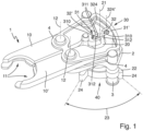
- FIG 1 1 is shown schematically a perspective side view of a clip device 1 for holding a beverage container in a neck portion.
- the clamp device comprises two clamp arms 10, 10' with a holding section 11 for holding the container to be held.
- the holding section 11 is designed, for example, to grip a container to be held below a neck ring of the container.
- the clamp arms 10, 10' are each arranged to be pivotable about a pivot axis 12 on a carrier plate 2 for opening and closing.
- the pivot axes 12 are oriented parallel to one another.
- the clamping device 1 also includes a control cam 20 that can be pivoted about a control cam pivot axis 21 oriented parallel to the pivot axes 12.
- a control cam 20 that can be pivoted about a control cam pivot axis 21 oriented parallel to the pivot axes 12.
- the clamp arms 10, 10' and the control cam 20 are coupled via a coupling mechanism 30.
- pivoting the control cam 20 about its control cam pivot axis 21 causes the clamp arms 10 to pivot about their pivot axes 12, so that the holding sections 11 can be moved toward or away from one another relative to one another in order to open and close the clamping device 1.
- the movement of the holding sections 11 relative to one another is controlled via the control cam 20 .
- the coupling mechanism 30 comprises two, each consisting of a slotted groove 31, 31' and one in the slotted groove 31; 31' guided control bolts 32, 32', each pair consisting of a slot groove 31, 31' and control bolts 32, 32' coupling a clamp arm 10, 10' to the control cam 20.
- each clamp arm 10, 10' has a slot 31, 31', in which the control pin 32, 32', which is associated with this slot groove 31, 31' and is arranged on the control cam 20, is guided.
- the "guide” of the control pin 32, 32' in the associated slotted groove 31, 31' is designed in such a way that the control pin 32, 32' moves translationally in a plane extending parallel to the control cam pivot axis 21 relative to the slotted slot 31, 31' and can roll and/or slide along the side walls of the slotted groove 31, 31', and can therefore move in a rotary manner relative to the slotted groove 31, 31'.
- the slot grooves 31, 31' each extend completely through the clamp arm 10, 10' in the direction of the control cam pivot axis 21. They can therefore be understood as through holes with an elongated hole shape.
- the slot grooves 31, 31' each have essentially the shape of a slot. Accordingly, they extend in a longitudinal extent 310 from a first end 312 to a second end 312 with side walls 311 running essentially parallel to one another between the two ends 312.
- the elongated grooves 31, 31' are each open on one side.
- one of the two ends 312 is formed as an open end.
- the open end 312 of each slot groove 31, 31' is the end 312 that is closer to the control cam pivot axis 21.
- control cam 20 In order to be able to change the position of the control cam 20 when it is installed on a container transport device of a container treatment device, it has an interaction part 22 which extends radially outwards in relation to the control cam pivot axis 21 and on which, for example, an interaction bolt provided at a fixed position of the container treatment device strikes and so a pivoting of the control cam 20 can cause.
- the clamping device 1 also includes an optional stop 3 arranged on the carrier plate 2, which, viewed in the circumferential direction in relation to the control cam pivot axis 21, is located between two radially outwardly extending arms 24 of the control cam 20 is arranged.
- the control cam 20 can pivot about the control cam pivot axis 21 only in an angle 23 limited by the arms 24, which is 45° in the present case.
- the end positions of the control cam, in which the control cam 21 rests with one of its arms 24 on the stop 3, here are default positions with regard to the opening and closing positions of the holding portions 11. One end position represents an open default position, respectively, and the other end position represents a closed default position.
- the holding sections 11 can be adjusted accordingly by pivoting the control cam 20 between a closed position specified by the closed default position, as in FIG figure 1 shown, and moved to an open position predetermined by the default open position.
- the clamping device 1 also includes a holding device for holding the control cam 21 in a default position, ie in the closed default position or the open default position, as will be explained in more detail later.
- the arms 24 and the control pins 32, 32' are designed in such a way that a lever arm ratio between a lever arm present between the control cam pivot axis 21 and a predetermined point of application for an interaction element of the container treatment device for switching the control cam 20 and the lever arm between the control pin 32, 32' and the control cam pivot axis 21 lever arms present is between substantially 5 to 1 and 3 to 1, and preferably is substantially 4 to 1. “Substantially” is to be understood here as meaning that differences resulting from the different distances 320, 320′ lie within the rounding or tolerance of the lever arm ratio. In other words, the difference between the distances 320, 320' is so small that the resulting differences compared to the lever arms described above can be ignored.
- a slide plate 4 is provided between the carrier plate 2 and the clamp arms 10 , which provides a sliding bearing of the clamp arms 10 with respect to the carrier plate 2 .
- a slide plate 4 is also provided above the clamp arms 10, which is intended to provide a sliding bearing of the clamp arms 10 with respect to a container transport device to which the clamp device 1 can be attached.
- the clamp arms 10 and/or the carrier plate 2 can be made of a metal, preferably a steel alloy.
- the sliding plates 4 are made of a material different from the carrier plate 2 and/or the clamp arms 10, for example a plastic, a copper alloy or a brass alloy.
- FIG. 2 shows a schematic plan view of a clamping device 1 in a further embodiment.
- Clamping device 1 shown corresponds essentially to that of FIG figure 1 .
- the embodiments figure 1 and figure 2 has in particular in common that the clamp arms 10, 10' are not formed symmetrically, specifically with regard to the area around the slot grooves 31, 31'.
- the slotted groove 31 arranged on the clamp arm 10 has a first distance from the pivot axis 12 of the clamp arm 10 and the slotted groove 31' arranged on the clamp arm 10' has a second distance from the pivot axis 12' of the clamp arm 10', the amount of the second distance is greater than the magnitude of the first distance.
- the distances correspond to the length of the lever arms.
- the control pin 32 guided in the slotted slot 10 is at a first distance 320 from the Control cam pivot axis 21 is arranged on the control cam 20, which is smaller than the distance between the second control bolt 32' guided in the slot groove 31' and the control cam pivot axis 21.
- the above distances are selected in such a way that the transmission ratio provided by the pair of slot groove 31 and control pin 32 is Essentially corresponds to the transmission ratio provided by the pair of slotted groove 31' and control pin 32'.
- control cam 20 In the respective in the figures 1 and 2 shown closed position of the holding sections 11, the control cam 20 is in the default closed position.
- the control bolts 32, 32' are arranged on the control cam 20 in such a way that when the control cam 20 is in the default closed position, viewed in the direction of the control cam pivot axis 21, they lie on a line which is oriented perpendicular to a plane 35 formed by the two pivot axes 12, 12' .
- control bolts 32' in the embodiment according to FIG figure 2 connected by a connecting wall 324, which can be understood as two cam portions 322 connected to each other.
- a connecting wall 324 which can be understood as two cam portions 322 connected to each other.
- FIG. 12 schematically shows a plan view of the clamping device 1 from FIG figure 2 in an open position, in which the holding sections 11 are in their open position. Accordingly, the control cam 20 is pivoted by the specified angle 23 of 45° in the present case in relation to its orientation in figure 2 before.
- the coupling arms 10, 10' are each connected to their Pivot axis 12, 12' pivoted.
- control bolts 32, 32' move between the default open position and the default closed position along the slot grooves 31, 31' assigned to them. Relative to the slotted groove in 31, 31', this movement of the control bolts 32, 32' includes a translatory component of movement along the longitudinal extension 310 of the slotted slot in 31, 31' and a rotational component of movement, thus a sliding movement relative to the side walls 311 of the slotted slot 31, 31'.
- control bolts 32, 32′ comprise a curved section in relation to their respective central longitudinal axis 325, presently in the form of a section 321 in the shape of a circular arc figure 1 the arcuate section 321 runs over the entire circumference of the cylindrical control bolts 32, 32', the arcuate section 321 in the embodiment according to FIG Figures 2 and 3 bounded by the connecting wall 324 in each case.
- FIG. 4 and 5 each is a schematic top view of a clamping device 1 according to a further embodiment in a closed position ( figure 4 ) and an open position ( figure 5 ) shown.
- the clamping device 1 essentially corresponds to the clamping device 1 in FIG figure 1 .
- the clamping device 1 In contrast to the clamping devices 1 from figure 1 and the Figures 2 and 3 has the clamping device 1 according to the Figures 4 and 5 such a structure that the control bolts 32, 32' in the closed position of the clamping device 1, i.e. when the holding sections 11 are in their closed position and accordingly the control cam 20 is in the closed default position, viewed perpendicularly to the control cam pivot axis 21 lie on a line 34 which lies essentially parallel to the plane 35 formed by the pivot axes 12, 12'.
- FIG figure 6 shows schematically a perspective side view of a clamping device 1 according to a further embodiment, which is essentially that of FIG figure 1 is equivalent to.
- the control pin 32 has a securing web 323 at its front end, in the present case designed in the form of a circular one arranged concentrically with the longitudinal center axis 325 of the control pin 32 Flange, the outer diameter of which is greater than the width of the slotted groove 31 transversely to its longitudinal extension 310.
- This provides a form fit between the clamp arm 10 and the control cam 20 in the direction of the control cam pivot axis 21, so that the control cam 20 in the figure 6 shown, is held on the clamp arm 10 not attached to a container transport device.
- figure 7 schematically a view from below of the clamping device 1 from figure 1
- figure 8 schematically a perspective side view from below of a portion of the clamping device 1 from figure 1 .
- the prestressing device 40 is designed to hold or prestress the control cam 20 in a predetermined end position, ie the open default position or the closed default position.
- the prestressing device 40 comprises a spring element 41 arranged on the control cam 20, which is presently provided in the form of a curved leaf spring and extends between the arms 24 in relation to the control cam pivot axis essentially in the circumferential direction.
- spring element 41 has, on its side pointing in the direction of roller 42, a curvature indicated by radius of curvature 410, which is greater than a curvature indicated by radius 450 of a geometric pitch circle 45 that is concentric with control cam pivot axis 21 at the level of the connection points of spring element 41 the arms 24 of the interaction part 22.
- the stop 3 is formed by a roller 42 which is rotatably mounted on the carrier plate 2 via a bearing bolt 48 and which is in contact with the spring element 41 or rolls over it, delimited by the arms 24 providing the end positions.
- the spring element 41 Since the spring element 41 curves radially outwards relative to the pitch circle diameter 45 in relation to the control cam pivot axis 21 due to the smaller radius of curvature 410 compared to the radius 450, the spring element 41 exerts a spring force on the roller 42, which is greatest in the middle of the spring element 41 is, and thereby biases the roller 42 in the respective end position. Due to this bias, the control cam 20 and correspondingly the clamp arms 10 are in a stable state, namely either in the open position or in the closed position.
- the control cam 20 In order to move the clamp arms 10 out of the respective position, the control cam 20 must be moved against the tension provided via the spring element 41 . In other words, the force generated when the roller 42 rolls over the spring element 41 by the resulting elastic bending of the spring element 41 must be overcome in order to enable a relative movement of the roller 42 and control cam 20 . If the apex, and thus the middle of the spring element 41, has been overcome, the spring force provided by the spring element 41 due to its bending supports the movement of the control cam 20 into the respective end position.
- the extension angle of the interaction section 22 or of the arms 24 in the circumferential direction in relation to the control cam pivot axis 21 is indicated by reference number 25, which angle is 45° in the present case.
- roller 42 is mounted on the bearing bolt 48 eccentrically with respect to a bearing bolt 48 which is attached to the support plate 2 in a rotationally fixed manner.
- the axis of rotation 43 of the roller 42 has a predetermined distance from the bearing center axis 44 of the bearing pin 48 .
- the bearing pin 48 can be prestressed in the circumferential direction in relation to the central bearing axis 44 in such a way that the bearing roller 42 is pressed in the radial direction towards the control cam 20 in relation to the control cam pivot axis 21, preferably by a torsion spring (not shown here) between the carrier plate 2 and bearing pin 48 is provided.
- the prestressing force which holds the control cam 20 in one of the end positions is composed of the spring force on the side of the bearing roller 42 and the spring force on the side of the spring element 41 .
- a rigid element can be provided instead of the elastic spring element 41, which, analogous to the spring element 41, has a curvature that is greater than that of the pitch circle 45. Then, the biasing force for holding the control cam 20 in one of the end positions is provided solely by the spring member (not shown) on the roller 42 side.
- the shape of the arms 24 and the position of the roller 42 are specified in such a way that a lever arm ratio between a lever arm present between the control cam pivot axis 21 and the contact area of the roller 42 on the arms 24 and the lever arm between the control bolts 32, 32' and the control cam pivot axis 21 respectively lever arms present is between substantially 6 to 1 and 2 to 1, and preferably is substantially 5 to 1, 4 to 1 or 3 to 1. “Substantially” is to be understood here as meaning that differences resulting from the different distances 320, 320′ lie within the rounding or tolerance of the lever arm ratio. In other words, the difference between the distances 320, 320' is so small that the resulting differences compared to the prescribed lever arms can be ignored.
- Out of figure 9 1 is a schematic view from below of a clamping device 1 according to a further embodiment.
- the clamping device 1 essentially corresponds to that of FIG figure 8 , with the exception of the design of the prestressing device 40.
- the control cam 20 instead of the continuous leaf spring, which is attached to the arms 24 at both ends or merges into them, the control cam 20 according to this embodiment has a substantially centered between the arms 24 up to the pitch circle 45 radially outwardly extending web 46, at the radially outward end of which a spring element 41 in the form of a bending beam with a free end extends on both sides essentially in the circumferential direction or tangentially thereto in relation to the control cam pivot axis 21, the free end in each case at a predetermined distance from the respective arm 24 ends.
- the spring elements 41 have a curvature that is smaller than the curvature of the pitch circle 45.
- the radius of curvature 410 of the spring elements 41 in relation to the control cam pivot axis 21 is greater than the radius 450 of the pitch circle 45, at the height of which the web 46 ends.
- the free ends 411 are radially further outward than the pitch circle 45 with respect to the control cam pivot axis 21 .
- a receptacle 49 is formed for receiving the roller 42 in the respective end position in a form-fitting manner, viewed in the circumferential direction in relation to the control cam pivot axis 21.
- the spring elements 41 are designed in such a way that they are elastically bent by a predetermined amount due to the roller 42 located in the receptacle 49 . Through this they provide a biasing force on the roller 42 which biases the roller 42 into the respective end position.
- control cam 20 In order to move the roller 42 out of the respective end position, the control cam 20 must be pivoted counter to the preload provided by the spring element 41 .
- This embodiment provides a particularly secure holding of the roller 42 or the control cam 20 in one of the end positions, since the pretensioning force provided via the spring element 41 on the roller 42 is greatest in the end positions.
- the roller 42 can optionally be analogous to the embodiment figure 8 be mounted eccentrically to the bearing center axis 44 and / or biased against the control cam.
- Out of figure 10 1 is a schematic view from below of a clamping device 1 according to a further embodiment.
- the clamping device 1 essentially corresponds to that of FIG figure 8 , with the exception of the configuration of the prestressing device 40.
- a bolt 47 is resiliently mounted on the control cam 20 in the radial direction relative to the control cam pivot axis 21 at a radial distance therefrom.
- the bolt 47 has analogous to the embodiment in figure 8 a curvature, indicated by the radius of curvature 410, which is greater than the curvature of the pitch circle 45.
- the bolt 47 is biased due to its resilient mounting against the roller 42 in the radial direction outwards.
- the roller 42 is held in one of the end positions by the bolt 47 .
- the roller 42 can optionally be analogous to the embodiment figure 8 be mounted eccentrically to the bearing center axis 44 and / or biased against the control cam.
- FIG figure 11 shows schematically a perspective side view of a clamping device 1 according to a further embodiment, which is essentially that of FIG figure 9 is equivalent to.
- control bolts 32 are analogous to the embodiment in figure 1 designed as parallel to the control cam pivot axis 21 extending cylinder pins. At their front ends, these are connected above the clamp arms 10 via a securing web 323 which extends between the two control bolts 32 .
- the safety bar 323 corresponds in terms of its functionality to that of FIG figure 6 described. In addition, it exhibits a compared to the embodiment figure 1 increased flexural rigidity of the control pin 32 in the radial direction based on the control cam pivot axis 21 ready.
- FIG figure 12 shows schematically a perspective side view of a clamping device 1 according to a further embodiment, which is essentially that of FIG figure 1 is equivalent to.
- the prestressing device 40 is designed as a magnetic prestressing device 40 .
- the stop 3 has a magnet 50 which interacts with a magnetic element 51 provided in each of the arms 24 in such a way that there is a magnetic attraction force between the magnet 50 and the respective magnetic element 51 when the control cam 20 is in one of the end positions .
- the control cam 20 is held in the respective end position by the magnetic force of attraction. In order to move the control cam 20 out of the respective end position, the magnetic force of attraction must be overcome.
- ferromagnetic bodies can also be provided in the arms 24.
- magnet 50 it is also possible to replace the magnet 50 with a ferromagnetic material, provided that there are magnetic elements 51 in the arms 24 that generate a magnetic field.
- FIG 13 shows schematically a top view of a clamping device 1 according to a further embodiment, which is essentially that of FIG figure 1 corresponds, wherein the biasing device 40 is a magnetic biasing device according to figure 12 is.
- the coupling mechanism 30 also differs in that the control bolts 32 are provided on the side of the clamp arms 10 . They extend from an in figure 13 side to be considered as the underside of the clamp arms 10, which is a side of the clamp arms 10 pointing in the direction of the control cam 20, parallel to the control cam pivot axis 21 with a predetermined length in the direction of the control cam 20.
- Each of the control bolts 32 is in an end face pointing in the direction of the clamp arms 10, in figure 13 the top of the control cam 20, provided blind hole-like slot groove 31 out.
- the control bolts 32 are each arranged on their clamp arm 10 at a distance or at a radius 326 from the pivot axis 12 of the respective clamp arm 10 . In other words, they pivot on the radius 326 around the respective pivot axis 12.
- the Figures 14 and 15 schematically show a top view and a side view of an upper part of a control cam 20 analogous to the embodiment according to FIG figure 13 ,
- the slotted grooves 31 are designed to be open on one side.
- the ends 312 ′ located radially on the outside in relation to the control cam pivot axis 21 are free or open ends 312' are formed.
- cleaning fluid which enters the slot grooves 31 during cleaning of a container treatment device having the clamping device 1 can flow out of the slot grooves 31 again at the open ends 312'.
- FIG 16 shows schematically a clamping device 1 according to a further embodiment.
- the clamping device 1 essentially corresponds to that of FIG figure 1 , with the following differences:
- the coupling mechanism 30 comprises exactly one pair of slotted groove 31 and control bolt 32.
- the pair of slotted groove 31 and control bolt 32 couples one of the clamp arms 10 directly to the control cam 20.
- This clamp arm 10 is also rotatably coupled to the other clamp arm 10' via a gear 60 .
- the coupling mechanism 30 includes exactly one pair of slotted groove 31 and control pin 32 in order to move the first clamp arm 10 by moving the control cam 20, and the coupling mechanism 30 also includes a rotary coupling unit, presently designed in the form of the gear 60 for coupling the first clamp arm 10 to the second clamp arm 10' so as to provide indirect coupling of the second clamp arm 10' to the control pin 20 via the clamp arm 10.
- Both clamp arms 10, 10' each have a toothed section 61 in the form of a gear wheel, which is arranged essentially concentrically with respect to the pivot axis 12 of the respective clamp arm 10, 10' and extends perpendicularly thereto.
- the toothed sections 61 engage with one another, so that the rotational coupling between the clamp arms 10, 10' is thereby formed.
- the control pin 32 also includes a securing bar 323 analogous to the embodiment figure 6 .
Abstract
Die vorliegende Erfindung betrifft eine Klammervorrichtung (1) zum Halten eines Behälters in einer Behälterbehandlungsvorrichtung, bevorzugt zum Halten eines Getränkebehälters in einem Halsabschnitt, umfassend zwei Klammerarme (10) mit einem Halteabschnitt (11) zum Halten des zu haltenden Behälters und einen um eine Steuernockenschwenkachse (21) schwenkbaren Steuernocken (20), wobei die Klammerarme (10) und der Steuernocken (20) über einen Koppelmechanismus (30) gekoppelt sind, so dass ein Schwenken des Steuernockens (20) um seine Steuernockenschwenkachse (21) ein Schwenken der Klammerarme (10) relativ zueinander bewirkt, und der Koppelmechanismus (30) zumindest ein Paar aus einer Langlochnut (31) und einem in der Langlochnut (31) geführten Steuerbolzen (32) zum Übertragen von Bewegungen des Steuernockens (20) auf die Klammerarme (10) umfasst.The present invention relates to a clamping device (1) for holding a container in a container treatment device, preferably for holding a beverage container in a neck section, comprising two clamping arms (10) with a holding section (11) for holding the container to be held and one about a control cam pivot axis ( 21) pivotable control cam (20), wherein the clamp arms (10) and the control cam (20) are coupled via a coupling mechanism (30), so that pivoting the control cam (20) about its control cam pivot axis (21) causes the clamp arms (10 ) relative to one another, and the coupling mechanism (30) comprises at least one pair of a slotted groove (31) and a control pin (32) guided in the slotted groove (31) for transmitting movements of the control cam (20) to the clamp arms (10).
Description
Die vorliegende Erfindung betrifft eine Klammervorrichtung zum Halten eines Behälters in einer Behälterbehandlungsvorrichtung, beispielsweise zum Halten eines Getränkebehälters in einem Halsabschnitt, um diesen innerhalb einer Getränkeabfüllanlage zu befüllen oder zu verschließen.The present invention relates to a clamping device for holding a container in a container treatment device, for example for holding a beverage container in a neck section in order to fill or close it within a beverage bottling plant.
Es ist bekannt, in Getränkeabfüllanlagen die jeweils zu befüllenden Behälter beziehungsweise bereits befüllte Behälter mittels Klammervorrichtungen durch die einzelnen Behandlungsstationen der Behälterbehandlungsvorrichtung zu transportieren. Dabei sind unterschiedliche Klammervorrichtungen bekannt, welche die jeweiligen zu behandelnden Behälter auf unterschiedliche Art und Weise halten.In beverage bottling plants, it is known to transport the containers to be filled or containers that have already been filled through the individual treatment stations of the container treatment device by means of clamping devices. Different clamping devices are known which hold the respective containers to be treated in different ways.
So sind beispielsweise passive Klammervorrichtungen bekannt, welche lediglich durch das Einschieben des jeweiligen Behälters in die Klammervorrichtung elastisch vorgespannt werden und dann den Behälter halten. Aus der
Weiterhin bekannt sind aktive Klammervorrichtungen, bei welchen ein Öffnen und Schließen der jeweiligen Halteabschnitte der Klammervorrichtung mittels eines Aktuators aktiv durchgeführt wird. Solche aktiven Klammervorrichtungen dienen insbesondere dazu, eine sichere und schonende Übernahme der jeweiligen Behälter von einer vorhergehenden Klammervorrichtung zu ermöglichen oder eine ebenso sichere und behälterschonende Übergabe der Behälter an eine nachfolgende Klammervorrichtung zu gewährleisten. Insbesondere kann durch das aktive Öffnen und Schließen der jeweiligen Klammervorrichtung eine erhöhte Reibung an dem jeweiligen Behälter, welche beispielsweise zu einem Verkratzen des Behälters führen könnte, vermieden werden und andererseits kann eine vorgegebene Haltekraft beziehungsweise Klemmkraft eingestellt werden, welche innerhalb eines vorgegebenen Toleranzbereichs der Behälterdimension eingehalten werden kann. Solche aktiven Klammervorrichtungen setzen sich aus einer Vielzahl von Einzelteilen, beispielsweise Klammerarmen, Buchsen, Federelement, Vorspannelementen und entsprechenden Verbindungselementen zum sicheren Verbinden der vorgenannten Teile, zusammen. Derart aufgebaute Klammervorrichtungen sind mithin aufwendig zu reinigen und weisen einen entsprechend hohen Fertigungsaufwand auf.Also known are active clamping devices in which the respective holding sections of the clamping device are opened and closed actively by means of an actuator. Such active clamping devices are used in particular to enable the respective containers to be transferred safely and gently from a preceding clamping device or to ensure an equally safe and container-friendly transfer of the containers to a subsequent clamping device. In particular, by actively opening and closing the respective clamping device, increased friction on the respective container, which could lead to scratching of the container, for example, can be avoided and, on the other hand, a predetermined holding force or clamping force can be set, which is maintained within a predetermined tolerance range of the container dimensions can be. Such active clamping devices are composed of a large number of individual parts, for example clamping arms, bushings, spring elements, prestressing elements and corresponding connecting elements for securely connecting the aforementioned parts. Clamping devices constructed in this way are therefore difficult to clean and have a correspondingly high production cost.
Aus der
Aus der
Die
Bei Klammervorrichtungen mit einseitiger Vorspannung der Klammerarme in eine Position, die durch Betätigung des Steuernockens entgegen der Vorspannung in eine andere Position bewegt werden können, und durch Lösen beziehungsweise erneutes Schalten des Steuernockens von selbst in die eine vorgespannte Position zurückbewegt werden, ist der Vorgang des vorspannungsbedingten Rückbewegens mit einer gewissen Trägheit behaftet. Demgemäß kann es zu ruckartigem Greifen des Behälters und ruckartigem Lösen des Haltens des Behälters kommen. Ferner kann es bei derartigen aktiven Klammervorrichtungen zu einem hohen Verschleiß zwischen Klammerarmen und Steuernocken kommen, da letzterer stets gegen die einseitig gerichtete Vorspannung arbeiten muss.In the case of clamping devices with one-sided prestressing of the clamp arms into a position which can be moved into another position by actuating the control cam counter to the prestressing, and which can be moved back into the one prestressed position by releasing or switching the control cam again, the process is prestressed associated with a certain inertia. Accordingly, it can jerky grasping of the container and jerky releasing of the holding of the container. Furthermore, with such active clamping devices, there can be a high degree of wear between the clamping arms and the control cam, since the latter always has to work against the unidirectional pretension.
Ausgehend von dem bekannten Stand der Technik ist es eine Aufgabe der vorliegenden Erfindung, eine verbesserte Klammervorrichtung zum Halten eines Behälters in einer Behälterbehandlungsvorrichtung, bevorzugt zum Halten eines Getränkebehälters in einem Halsabschnitt bereitzustellen.Proceeding from the known state of the art, it is an object of the present invention to provide an improved clamping device for holding a container in a container treatment device, preferably for holding a beverage container in a neck section.
Die Aufgabe wird durch eine Klammervorrichtung zum Halten eines Behälters in einer Behälterbehandlungsvorrichtung, bevorzugt zum Halten eines Getränkebehälters in einem Halsabschnitt, mit den Merkmalen des Anspruchs 1 gelöst. Vorteilhafte Weiterbildungen ergeben sich aus den Unteransprüchen, der Beschreibung und den Figuren.The object is achieved by a clamping device for holding a container in a container treatment device, preferably for holding a beverage container in a neck section, with the features of
Entsprechend wird eine Klammervorrichtung zum Halten eines Behälters in einer Behälterbehandlungsvorrichtung, bevorzugt zum Halten eines Getränkebehälters an einem Halsabschnitt, vorgeschlagen, umfassend zwei Klammerarme mit einem Halteabschnitt zum Halten des zu haltenden Behälters und einen um eine Steuernockenschwenkachse schwenkbaren Steuernocken, wobei die Klammerarme und der Steuernocken über einen Koppelmechanismus gekoppelt sind, so dass ein Schwenken des Steuernockens um seine Steuernockenschwenkachse ein Schwenken der Klammerarme relativ zueinander bewirkt.Accordingly, a clamp device for holding a container in a container treatment device, preferably for holding a beverage container by a neck section, is proposed, comprising two clamp arms with a holding section for holding the container to be held and a control cam pivotable about a control cam pivot axis, the clamp arms and the control cam via are coupled to a coupling mechanism, so that pivoting of the control cam about its control cam pivot axis causes the clamp arms to pivot relative to one another.
Der Koppelmechanismus umfasst zumindest ein Paar aus einer Langlochnut und einem in der Langlochnut geführten Steuerbolzen zum Übertragen von Bewegungen des Steuernockens auf die Klammerarme.The coupling mechanism comprises at least one pair of a slotted slot and a control pin guided in the slotted slot for transmitting movements of the control cam to the clamp arms.
Anders ausgedrückt sind die Klammerarme und der Steuernocken über zumindest eine Langlochnut und einen der Langlochnut zugeordneten und in der Langlochnut geführten Steuerbolzen zum Übertragen von Bewegungen des Steuernockens auf die Klammerarme gekoppelt, so dass ein Schwenken des Steuernockens um seine Steuernockenschwenkachse ein Schwenken der Klammerarme relativ zueinander bewirkt. Die vorbeschriebene Kopplung kann als Koppelmechanismus verstanden werden.In other words, the clamp arms and the control cam are coupled via at least one slotted slot and a control bolt assigned to the slotted slot and guided in the slotted slot for transmitting movements of the control cam to the clip arms, so that pivoting the control cam about its control cam pivot axis causes the clip arms to pivot relative to one another . The coupling described above can be understood as a coupling mechanism.
Dadurch, dass der Koppelmechanismus zumindest ein Paar aus einer Langlochnut und einem in der Langlochnut geführten Steuerbolzen zum Übertragen von Bewegungen des Steuernockens auf die Klammerarme umfasst, kann eine dauerhafte, sprich permanente Zwangsführung zumindest eines Klammerarmes durch den Steuernocken bereitgestellt werden. Anders ausgedrückt ist aufgrund der (via des Koppelmechanismus bereitgestellten) Koppelung die Position und eine Bewegung der Klammerarme von der Position und einer Bewegung des Steuernockens stets vorgegeben.Because the coupling mechanism comprises at least one pair of a slotted groove and a control pin guided in the slotted groove for transmitting movements of the control cam to the clamp arms, permanent, i.e. permanent forced guidance of at least one clamp arm can be provided by the control cam. In other words, due to the coupling (provided via the coupling mechanism), the position and a movement of the clamp arms are always predetermined by the position and a movement of the control cam.
Entsprechend kann verhindert werden, dass die Klammerarme und der Steuernocken bei einem Schaltimpuls auf den Steuernocken, welcher eine abrupte Bewegung des Steuernockens erzeugt, kurzzeitig außer Eingriff gelangen beziehungsweise den Kontakt zueinander verlieren, wie es bei einseitig vorgespannten konventionellen Klammervorrichtungen der Fall sein kann, etwa bei ungenügender Federkraft der einseitigen Vorspannung, um dann wieder aneinander zu stoßen. Das Greifen und Loslassen des durch die Klammervorrichtung zu haltenden Behälters kann mithin vergleichsweise sanft erfolgen, ohne, dass unkontrollierte Stöße beim Öffnen oder Schließen der Klammerarme auftreten.Accordingly, it is possible to prevent the clamping arms and the control cam from briefly disengaging or losing contact with one another when there is a switching pulse on the control cam, which causes an abrupt movement of the control cam, as can be the case with conventional clamping devices that are pretensioned on one side, for example in insufficient spring force of the one-sided preload, and then bump into each other again. The container to be held by the clamping device can therefore be gripped and released comparatively gently, without uncontrolled impacts occurring when the clamp arms are opened or closed.
Ferner kann durch die permanent vorhandene Führung, bereitgestellt durch das Paar aus Langlochnut und Steuerbolzen, eine definierte Anlage der Halteabschnitte an den zu haltenden Behälter erzielt werden.Furthermore, a defined contact of the holding sections on the container to be held can be achieved by the permanently present guide, provided by the pair of slotted groove and control pin.
Eine derartig ausgebildete Klammervorrichtung kann folglich in Vergleich zu herkömmlichen Vorrichtungen während des Betriebs einen besonders niedrigen Verschleiß unterliegen, insbesondere in Bereichen, in welchen die Klammerarme und der Steuernocken gekoppelt sind, was sich wiederum positiv auf die Lebensdauer der Komponenten der Klammervorrichtung auswirkt.A clamping device designed in this way can consequently be subject to particularly low wear during operation compared to conventional devices, particularly in areas in which the clamping arms and the control cam are coupled, which in turn has a positive effect on the service life of the components of the clamping device.
Hinsichtlich einer die Klammervorrichtung aufweisenden Behälterbehandlungsvorrichtung können im Vergleich zu Behälterbehandlungsvorrichtungen mit herkömmlichen Klammervorrichtungen die Wartungsintervalle aufgrund des verringerten Verschleißes vergrößert sein.With regard to a container treatment device having the clamping device, the maintenance intervals can be increased in comparison to container treatment devices with conventional clamping devices due to the reduced wear.
Ferner kann durch das stets zwangsgeführte Bewegen der Halteabschnitte und des Reduzierens im Vergleich zu herkömmlichen Klammervorrichtungen beziehungsweise gar des Vermeidens des Auftretens von Stößen während des Öffnens und/oder Schließens der Klammerarme, gesteuert durch den Steuernocken, ein Beschädigen des zu haltenden Behälters und/oder ein Austreten von im Behälter befindlichen Füllguts, etwa einem Getränk, und von damit einhergehenden Kontaminationen der Klammervorrichtung und anderen Bereichen einer die Klammervorrichtung Behälterbehandlungsvorrichtung und der Außenseite des Behälters reduziert oder gar vermieden werden.Furthermore, the always forcibly guided movement of the holding sections and the reduction compared to conventional clamping devices or even the avoidance of impacts occurring during the opening and/or closing of the clamp arms, controlled by the control cam, can damage the container to be held and/or a Leakage of contents in the container, such as a drink, and of those associated with it Contamination of the clamping device and other areas of a container treatment device and the outside of the container can be reduced or even avoided.
Der Ausdruck "Schwenkachse" wird als geometrische Achse verstanden, welche einen Rotationsmittelpunkt darstellt, und beschreibt in diesem Dokument insbesondere eine feste Schwenkachse, mithin eine hinsichtlich der Klammervorrichtung ortsfest angeordnete Achse. Eine sich verschiebende Achse im Sinne eines Momentanpols wird mithin nicht als "Schwenkachse" verstanden. Ein sich in einer Ebene zugleich rotatorisch und translatorisch bewegender Körper führt kein Schwenken um eine feste Achse auf, er weist demgemäß keine Schwenkachse wie sie hier verstanden wird auf.The expression "pivoting axis" is understood as a geometric axis which represents a center of rotation and describes in this document in particular a fixed pivoting axis, ie an axis arranged in a stationary manner with respect to the clamping device. A shifting axis in the sense of an instant center is therefore not understood as a "pivoting axis". A body that moves both rotationally and translationally in one plane does not pivot about a fixed axis; accordingly, it does not have a pivot axis as understood here.
Die geometrische Schwenkachse kann selbstredend in Form einer mechanischen Achse beziehungsweise Welle in an sich bekannter Weise bereitgestellt beziehungsweise ausgebildet sein. Beispielsweise kann ein Achszapfen, ein Stift oder ein Bolzen an einer Trägerplatte der Klammervorrichtung angeordnet sein, an welchem beispielsweise ein Klammerarm im Sinne eine Welle-Nabe-Verbindung schwenkbar gelagert ist. Weiterhin kann beispielsweise der Steuernocken einen Wellenabschnitt umfassen, welcher in einer Bohrung in der Trägerplatte drehbar gelagert ist.The geometric pivot axis can of course be provided or designed in the form of a mechanical axis or shaft in a manner known per se. For example, an axle journal, a pin or a bolt can be arranged on a carrier plate of the clamping device, on which, for example, a clamp arm is pivotably mounted in the sense of a shaft-hub connection. Furthermore, for example, the control cam can include a shaft section which is rotatably mounted in a bore in the carrier plate.
Als "Langlochnut" wird hier eine Nut verstanden, die im Wesentlichen die Form eines Langlochs aufweist, mithin sich in einer Längserstreckung von einem ersten Ende zu einem zweiten Ende erstreckt und zwischen den beiden Enden im Wesentlichen parallel zueinander verlaufende, anders ausgedrückt quer zur Längserstreckung mit einem festen Abstand zueinander verlaufende Seitenwände umfasst, welche vorzugsweise gerade verlaufen, mithin einen unendlichen Krümmungsradius aufweisen.A "slot groove" is understood here to mean a groove that essentially has the shape of a slot, thus extending in a longitudinal extension from a first end to a second end and between the two ends running essentially parallel to one another, in other words transverse to the longitudinal extension comprises side walls running at a fixed distance from one another, which preferably run straight and therefore have an infinite radius of curvature.
Die Längserstreckung der Langlochnut ist hierbei bezogen auf eine senkrecht zur Steuernockenschwenkachse orientierte Ebene. Mit anderen Worten ist die Langloch-Form der Langlochnut betrachtet in Richtung der Steuernockenschwenkachse zu erkennen.The longitudinal extent of the slot groove is related to a plane oriented perpendicularly to the control cam pivot axis. In other words, the slot shape of the slot groove can be seen viewed in the direction of the control cam pivot axis.
Die Langlochnut erstreckt sich im Sinne einer Nut als Vertiefung in einen Körper mit der zuvor beschriebenen Langloch-Form, und zwar in Richtung der Steuernockenschwenkachse mit einer vorgegebenen Tiefe und/oder zumindest teilweise durch den gesamten Körper.The slotted groove extends in the sense of a groove as a depression in a body with the previously described slotted hole shape, namely in the direction of the control cam pivot axis with a predetermined depth and/or at least partially through the entire body.
Gemäß einer bevorzugten Ausführungsform sind die Halteabschnitte durch das Schwenken des Steuernockens in eine Öffnungsposition und/oder in eine Schließposition bewegbar.According to a preferred embodiment, the holding sections can be moved into an open position and/or into a closed position by pivoting the control cam.
Weiterhin können die Klammerarme alternativ oder zusätzlich in einer senkrecht zur Steuernockenschwenkachse orientierten Ebene schwenkbar angeordnet sein.Furthermore, the clamp arms can alternatively or additionally be pivotably arranged in a plane oriented perpendicularly to the control cam pivot axis.
Vorzugsweise sind die die Klammerarme um zumindest eine parallel zur Steuernockenschwenkachse orientierte Schwenkachse schenkbar, wobei bevorzugt jeder Klammerarm jeweils eine Schwenkachse aufweist, um welche er schwenkbar ausgebildet ist.The clamp arms can preferably be pivoted about at least one pivot axis oriented parallel to the control cam pivot axis, with each clamp arm preferably having a pivot axis about which it is pivotable.
Ein besonders kompakter Aufbau und zudem eine günstige Kraftverteilung hinsichtlich über den Steuernocken eingeleiteter Kräfte und einer durch die Halteabschnitte auf den darin gehaltenen Behälter ausgeübten Kraft, sowie hinsichtlich eines Verhältnisses in Bezug auf einen Bewegungsumfang des Steuernockens gegenüber dem Bewegungsumfang der Halteabschnitte kann erzielt werden, wenn die Halteabschnitte, bevorzugt bezogen auf die zumindest eine Schwenkachse, auf einer Seite der Klammerarme angeordnet sind und das zumindest eine Paar aus Langlochnut und Steuerbolzen auf der anderen Seite angeordnet ist.A particularly compact design and also a favorable force distribution with regard to forces introduced via the control cam and a force exerted by the holding sections on the container held therein, as well as with regard to a ratio in relation to a scope of movement of the control cam compared to the scope of movement of the holding sections can be achieved if the Retaining sections, preferably in relation to the at least one pivot axis, are arranged on one side of the clamp arms and the at least one pair of slotted groove and control pin is arranged on the other side.
Gemäß einer weiteren bevorzugten Ausführungsform sind die zumindest eine Langlochnut auf Seiten der Klammerarme angeordnet und der zumindest eine Steuerbolzen am Steuernocken angeordnet. Mit anderen Worten kann zumindest einer der Klammerarme eine Langlochnut umfassen, in welcher der dieser Langlochnut zugeordnete, am Steuernocken angeordnete Steuerbolzen geführt ist.According to a further preferred embodiment, the at least one slotted groove is arranged on the side of the clamp arms and the at least one control bolt is arranged on the control cam. In other words, at least one of the clamp arms can comprise a slotted slot, in which the control bolt, which is assigned to this slotted slot and is arranged on the control cam, is guided.
Alternativ oder zusätzlich kann zumindest ein Steuerbolzen auf Seiten der Klammerarme angeordnet sein und die diesem Steuerbolzen zugeordnete zumindest eine Langlochnut am Steuernocken angeordnet sein. Anders ausgedrückt kann zumindest einer der Klammerarme einen Steuerbolzen umfassen, welcher in der diesem Steuerbolzen zugeordneten, am Steuernocken angeordneten Langlochnut geführt ist.Alternatively or additionally, at least one control bolt can be arranged on the side of the clamp arms and the at least one slotted groove assigned to this control bolt can be arranged on the control cam. In other words, at least one of the clamp arms can comprise a control pin, which is guided in the slotted groove arranged on the control cam and assigned to this control pin.
Gemäß einer weiteren bevorzugten Ausführungsform umfasst der Koppelmechanismus zwei Paare aus Langlochnut und Steuerbolzen, wobei jeweils ein Paar aus Langlochnut und Steuerbolzen jeweils einen Klammerarm mit dem Steuernocken koppelt.According to a further preferred embodiment, the coupling mechanism comprises two pairs of elongated groove and control bolt, each pair of elongated groove and control bolt coupling a clamp arm to the control cam.
Alternativ kann der Koppelmechanismus auch genau ein Paar aus Langlochnut und Steuerbolzen umfassen, wobei das Paar aus Langlochnut und Steuerbolzen einen der Klammerarme mit dem Steuernocken koppelt und dieser Klammerarm mit dem anderen Klammerarm drehgekoppelt ist, bevorzugt über ein Getriebe, besonders bevorzugt ein Verzahnungsgetriebe.Alternatively, the coupling mechanism can also include exactly one pair of slotted groove and control bolt, with the pair of slotted groove and control bolt coupling one of the clamp arms to the control cam and this clamp arm being rotatably coupled to the other clamp arm, preferably via a gear, particularly preferably a toothed gear.
Mit anderen Worten umfasst der Koppelmechanismus gemäß der vorstehenden Ausführungsform das genau eine Paar aus Langlochnut und Steuerbolzen, um über eine Bewegung des Steuernockens den ersten Klammerarm zu bewegen, und ferner umfasst der Koppelmechanismus ein Drehkopplungseinheit zum Koppeln des ersten Klammerarmes mit dem zweiten Klammerarm, welcher nicht selbst direkt mit dem Steuerbolzen gekoppelt ist. Die Drehkopplungseinheit ist bevorzugt in Form eines Getriebes, besonders bevorzugt eines Verzahnungsgetriebes, ausgebildet. Der Steuernocken ist folglich mit einem Klammerarm über das Paar aus Langlochnut und Steuerbolzen direkt beziehungsweise unmittelbar gekoppelt und mit dem anderen Klammerarm über den direkt gekoppelten Klammerarm und die Drehkoppeleinheit mittelbar gekoppelt.In other words, according to the above embodiment, the coupling mechanism includes the exactly one pair of long hole groove and control bolt in order to move the first clamp arm via a movement of the control cam, and further the coupling mechanism includes a rotary coupling unit for coupling the first clamp arm with the second clamp arm, which is not itself is coupled directly to the control pin. The rotary coupling unit is preferably designed in the form of a gear, particularly preferably a toothed gear. The control cam is consequently directly or directly coupled to one clamp arm via the pair of slotted groove and control pin and indirectly coupled to the other clamp arm via the directly coupled clamp arm and the rotary coupling unit.
Vorteilhafterweise weisen beide Klammerarme jeweils einen zahnradförmigen Verzahnungsabschnitt auf, die bevorzugt im Wesentlichen konzentrisch zu der Schenkachse des jeweiligen Klammerarmes angeordnet sind und sich senkrecht zu dieser erstrecken. Die Verzahnungsabschnitte stehen miteinander in Eingriff, so dass dadurch die Drehkopplung zwischen den Klammerarmen ausgebildet ist.Advantageously, both clamp arms each have a toothed section in the form of a gear wheel, which are preferably arranged essentially concentrically with respect to the pivot axis of the respective clamp arm and extend perpendicularly thereto. The toothed portions engage with each other, thereby forming the rotational coupling between the clip arms.
Es hat sich als vorteilhaft herausgestellt, zumindest einen Steuerbolzen relativ zur Steuernockenschwenkachse exzentrisch anzuordnen.It has proven to be advantageous to arrange at least one control bolt eccentrically relative to the control cam pivot axis.
Da der zumindest eine Steuerbolzen exzentrisch zur Steuernockenschwenkachse angeordnet ist, liegen vorgenannte nicht konzentrisch zueinander vor. Vielmehr weisen die Steuernockenschwenkachse und der zumindest eine Steuerbolzen, insbesondere ein Längsmittelachse des Steuernockens in einer senkrecht zur Steuernockenschwenkachse orientierten Ebene einen Abstand zueinander auf. Der Abstand kann ein veränderlicher Abstand sein, beispielsweise, wenn der zumindest eine Steuerbolzen auf Seiten der Klammerarme, mit anderen Worten an einem der Klammerarme, angeordnet ist, mit nochmals anderen Worten, wenn einer der Klammerarme den Steuerbolzen aufweist.Since the at least one control bolt is arranged eccentrically to the control cam pivot axis, the aforementioned are not concentric with one another. Rather, the control cam pivot axis and the at least one control bolt, in particular a longitudinal center axis of the control cam, are at a distance from one another in a plane oriented perpendicular to the control cam pivot axis. The distance can be a variable distance, for example if the at least one control pin is arranged on the side of the clamp arms, in other words on one of the clamp arms, in other words if one of the clamp arms has the control pin.
Gemäß einer weiteren bevorzugten Ausführungsform ist ein erstes Langloch an einem ersten Klammerarm angeordnet und weist einen ersten Abstand zur Schwenkachse des ersten Klammerarms auf, und ferner ist ein zweites Langloch am zweiten Klammerarm angeordnet und weist einen zweiten Abstand zur Schwenkachse des zweiten Klammerarms auf. Vorzugsweise ist der Betrag des zweiten Abstands größer ist als der Betrag des ersten Abstands, und ferner ist bevorzugt ein in der ersten Langlochnut geführter erster Steuerbolzen mit einem ersten Abstand zur Steuernockenschwenkachse am Steuernocken angeordnet und ist ein in der zweiten Langlochnut geführter zweiter Steuerbolzen mit einem zweiten Abstand zur Steuernockenschwenkachse, dessen Betrag größer ist als jener des ersten Abstands, am Steuernocken angeordnet. Dadurch kann ein besonders kompakter Aufbau der Klammervorrichtung erzielt werden.According to a further preferred embodiment, a first elongated hole is arranged on a first clamp arm and has a first distance from the pivot axis of the first clamp arm, and a second elongated hole is arranged on the second clamp arm and has a second distance from the pivot axis of the second clamp arm. Preferably, the amount of the second distance is greater than the amount of the first distance, and furthermore, a first control pin guided in the first slot groove is preferably arranged on the control cam at a first distance from the control cam pivot axis and a second control pin guided in the second slot groove is arranged with a second distance to control cam swivel axis, whose amount is greater than that of the first distance, arranged on the control cam. As a result, a particularly compact design of the clamping device can be achieved.
Die vorstehenden Abstände sind dabei vorzugsweise so gewählt, dass das durch das erste Paar aus erster Langlochnut und erstem Steuerbolzen bereitgestellte Übersetzungsverhältnis im Wesentlichen dem durch das zweite Paar aus zweiter Langlochnut und zweitem Steuerbolzen bereitgestellten Übersetzungsverhältnis entspricht. Dann kann ein symmetrisches Schwenken beider Klammerarme erzielt werden.The above distances are preferably chosen such that the transmission ratio provided by the first pair of the first slotted groove and the first control pin essentially corresponds to the transmission ratio provided by the second pair of the second slotted slot and the second control pin. Then a symmetrical pivoting of both clamp arms can be achieved.
Gemäß einer weiteren bevorzugten Ausführungsform ist zumindest eine Langlochnut zumindest teilweise als Durchgangsbohrung ausgebildet und/oder ist zumindest eine Langlochnut zumindest teilweise als Sacklochbohrung ausgebildet und/oder ist zumindest eine Langlochnut einseitig offen ausgebildet und/oder ist zumindest eine Langlochnut zweiseitig offen ausgebildet.According to a further preferred embodiment, at least one slotted groove is at least partially designed as a through hole and/or at least one slotted slot is at least partially designed as a blind hole and/or at least one slotted slot is designed to be open on one side and/or at least one slotted slot is designed to be open on two sides.
Gemäß einer weiteren bevorzugten Ausführungsform umfasst der zumindest eine Steuerbolzen einen bezogen auf eine Längsmittelachse des Steuerbolzens gekrümmten Abschnitt, bevorzugt einen kreisbogenförmigen Abschnitt. Der Steuerbolzen kann dann in der Langlochnut relativ zu dieser einer rotatorische Bewegung ausführen, mithin an einer Wand der Langlochnut gleiten und/oder abrollen.According to a further preferred embodiment, the at least one control bolt comprises a section which is curved in relation to a central longitudinal axis of the control bolt, preferably a section in the shape of a circular arc. The control pin can then perform a rotational movement in the slotted groove relative to the latter, and can therefore slide and/or roll on a wall of the slotted groove.
Alternativ oder zusätzlich kann zumindest ein Steuerbolzen einen sich in einer senkrecht zur Steuernockenschwenkachse orientierten Ebene erstreckenden Nockenabschnitt aufweisen. Durch den Nockenabschnitt kann eine rotatorische Bewegung des Steuerbolzens relativ zur Langlochnut hinsichtlich ihres Umfangs auf einen vorgegebenen Betrag beschränkt werden. Beispielsweise kann der Steuernocken als Anschlag für eine Seitenwand des Langlochnut fungieren.Alternatively or additionally, at least one control bolt can have a cam section extending in a plane oriented perpendicular to the control cam pivot axis. A rotational movement of the control pin relative to the slot groove can be limited to a predetermined amount in terms of its circumference by the cam section. For example, the control cam can act as a stop for a side wall of the slot groove.
Ein besonders verschleißarmer Betrieb der Klammervorrichtung kann erzielt werden, wenn die Klammerarme, der Steuernocken und der Koppelmechanismus derart ausgebildet sind, dass ein Schwenken des Steuernockens zwischen einer Offenvorgabeposition und einer Schließvorgabeposition ein Bewegen der Halteabschnitte durch Schwenken der Klammerarme relativ zueinander zwischen einer Öffnungsposition und/oder einer Schließposition bewirkt, wobei der Steuernocken bezogen auf eine Ebene senkrecht zur Steuernockenschwenkachse bevorzugt zwischen der Offenvorgabeposition und der Schließvorgabeposition um einen vorgegebener Schwenkwinkel schwenkbar ist, wobei der vorgegebene Schwenkwinkel bevorzugt in einem Bereich zwischen 40° und 55°, besonders bevorzugt zwischen 44° und 50°, liegt und ganz besonders bevorzugt im Wesentlichen 45°, 46°, 47° oder 48° entspricht.A particularly low-wear operation of the clamping device can be achieved if the clamping arms, the control cam and the coupling mechanism are designed in such a way that pivoting the control cam between an open default position and a closed default position causes the holding sections to be moved by pivoting the clamp arms relative to one another between an open position and/or a closed position, wherein the control cam can be pivoted by a predetermined pivot angle, preferably between the default open position and the default closed position, relative to a plane perpendicular to the pivot axis of the control cam, the specified pivot angle preferably being in a range between 40° and 55°, particularly preferably between 44° and 50 °, and very particularly preferably corresponds essentially to 45°, 46°, 47° or 48°.
Gemäß einer weiteren bevorzugten Ausführungsform umfasst die Klammervorrichtung eine Vorspanneinrichtung, die ausgebildet ist, den Steuernocken in zumindest eine vorgegebene Endposition, welche bevorzugt der Offenvorgabeposition und/oder der Schließvorgabeposition entspricht, vorzuspannen.According to a further preferred embodiment, the clamping device comprises a pretensioning device which is designed to pretension the control cam in at least one predefined end position, which preferably corresponds to the default open position and/or the default closed position.
Vorzugsweise umfasst die Vorspanneinrichtung zumindest ein am Steuernocken angeordnetes Federelement und zumindest eine mit dem Federelement in Kontakt stehende Laufrolle, wobei das Federelement die Laufrolle bevorzugt in die zumindest eine Endposition vorspannt.The pretensioning device preferably comprises at least one spring element arranged on the control cam and at least one roller in contact with the spring element, with the spring element preferably pretensioning the roller into the at least one end position.
Gemäß einer weiteren bevorzugten Ausführungsform weist das Federelement in Bezug auf die Steuernockenschwenkachse eine Krümmung auf, die größer ist als eine Krümmung eines konzentrisch zur Steuernockenschwenkachse auf Höhe des Federelements vorliegenden geometrischen Teilkreises.According to a further preferred embodiment, the spring element has a curvature in relation to the control cam pivot axis which is greater than a curvature of a geometric pitch circle present concentrically to the control cam pivot axis at the height of the spring element.
Alternativ kann der Steuernocken einen sich zu einem konzentrisch zur Steuernockenschwenkachse vorliegenden geometrischen Teilkreis nach radial außen erstreckenden Steg aufweisen, von welchem sich bezogen auf die Steuernockenschwenkachse tangential zur radialen Richtung ein Federelement, bevorzugt beidseitig des Stegs jeweils ein Federelement, erstreckt. Bei einem derartigen Aufbau kann die durch das Federelement auf die Laufrolle bereitgestellte Vorspannung in der zumindest einen Endposition maximal sein.Alternatively, the control cam can have a web extending radially outwards relative to a geometric pitch circle concentric to the control cam pivot axis, from which a spring element, preferably a spring element on both sides of the web, extends tangentially to the radial direction in relation to the control cam pivot axis. With such a structure, the preload provided by the spring element on the roller can be at a maximum in the at least one end position.
Gemäß einer weiteren bevorzugten Ausführungsform ist zumindest ein Federelement als gekrümmte Blattfeder, in Form eines bezogen auf die Steuernockenschwenkachse radial federnd gelagerten Bolzens oder in Form eines Biegebalkens mit freiem Ende ausgebildet.According to a further preferred embodiment, at least one spring element is designed as a curved leaf spring, in the form of a bolt that is radially resiliently mounted relative to the control cam pivot axis, or in the form of a flexible beam with a free end.
Gemäß einer weiteren bevorzugten Ausführungsform ist die Laufrolle exzentrisch zu einer Lagermittelachse eines an einer Trägerplatte drehfest angebrachten Lagerbolzens am Lagerbolzen gelagert, wobei bevorzugt die Orientierung des Lagerbolzens um dessen Lagermittelachse veränderbar ist. So kann eine zwischen Lagerrolle und Federelement vorliegende Vorspannung in ihrer Höhe eingestellt werden. Durch ein Anstellen der Lagerrolle in Richtung Steuernockenschwenkachse kann die Vorspannkraft erhöht und in die andere Richtung entsprechend verringert werden.According to a further preferred embodiment, the roller is mounted on the bearing bolt eccentrically to a bearing center axis of a bearing bolt attached non-rotatably to a carrier plate, the orientation of the bearing bolt about its bearing center axis preferably being variable. In this way, the amount of prestressing present between the bearing roller and the spring element can be adjusted. By adjusting the bearing roller in the direction of the control cam pivot axis, the pretensioning force can be increased and correspondingly reduced in the other direction.
Zusätzlich oder alternativ kann die Lagerrolle bezogen auf die Steuernockenschwenkachse in radialer Richtung auf den Steuernocken vorgespannt sein. Beispielsweise kann die Lagerrolle in Richtung des Steuernockens federn gelagert sein, beispielsweise über eine Torsionsfeder.In addition or as an alternative, the bearing roller can be preloaded on the control cam in the radial direction relative to the control cam pivot axis. For example, the bearing roller can be spring-mounted in the direction of the control cam, for example via a torsion spring.
Gemäß einer weiteren bevorzugten Ausführungsform ist die Vorspanneinrichtung als magnetische Vorspanneinrichtung ausgebildet, wobei bevorzugt ein an einer Trägerplatte angeordneter Anschlag einen Magneten oder ein magnetisierbares und/oder ferromagnetisches Material aufweist, welcher beziehungsweise welches mit zumindest einem am Steuernocken, bevorzugt an einem sich bezogen auf die Steuernockenschwenkachse am Steuernocken nach radial außen erstreckenden Arm, vorgesehenen Magnetelement oder magnetisierbaren und/oder ferromagnetischen Material derart wechselwirkt, dass aufgrund einer magnetischen Anziehungskraft zwischen den vorgenannten der Steuernocken in zumindest einer Endposition gehalten ist.According to a further preferred embodiment, the pretensioning device is designed as a magnetic pretensioning device, with a stop arranged on a carrier plate preferably having a magnet or a magnetizable and/or ferromagnetic material, which has at least one on the control cam, preferably on one related to the control cam pivot axis on the control cam radially outwardly extending arm, magnetic element provided or magnetizable and/or ferromagnetic material interacts in such a way that the control cam is held in at least one end position due to a magnetic attraction force between the aforementioned.
Gemäß einer weiteren bevorzugten Ausführungsform weist der Steuerbolzen in Richtung der Steuernockenschwenkachse gesehen an einem stirnseitigen Ende einen Sicherungssteg zum Halten des Steuernockens an zumindest einem Klammerarm auf, wobei der Sicherungssteg bevorzugt in Form eines bevorzugt konzentrisch zur Längsmittelachse des Steuerbolzens angeordneten, bevorzugt kreisförmigen Flansches, ausgebildet ist, dessen Erstreckung senkrecht zur Steuernockenschwenkachse, bevorzugt dessen Außendurchmesser, größer ist als eine Breite der dem Steuernocken zugeordneten Langlochnut quer zu deren Längserstreckung, und/oder welcher in Form eines Verbindungssteges zwischen zwei Steuernocken ausgebildet ist.According to a further preferred embodiment, the control bolt, seen in the direction of the control cam pivot axis, has a securing web at a front end for holding the control cam on at least one clamp arm, the securing web preferably being configured in the form of a preferably circular flange which is preferably arranged concentrically to the longitudinal center axis of the control bolt , the extension of which is perpendicular to the control cam pivot axis, preferably whose outer diameter, is greater than a width of the slotted groove associated with the control cam transversely to its longitudinal extension, and/or which is designed in the form of a connecting web between two control cams.
Zwischen einer Trägerplatte der Klammervorrichtung, an welcher die Klammerarme und/oder der Steuernocken gelagert sind, und den Klammerarmen kann eine Gleitplatte zum Bereitstellen einer Gleitlagerung zwischen Trägerplatte und Klammerarmen vorgesehen sein.A slide plate for providing a slide bearing between the support plate and the clamp arms can be provided between a carrier plate of the clamp device, on which the clamp arms and/or the control cam are mounted, and the clamp arms.
Alternativ oder zusätzlich kann an einer Seite der Klammerarme, mit welcher sie an Behältertransportvorrichtung einer Behälterbehandlungsvorrichtung anbringbar sind, bevorzugt eine Oberseite der Klammerarme, eine Gleitplatte vorgesehen sein, welche eine Gleitlagerung der Klammerarme gegenüber der Behältertransportvorrichtung, an welchem die Klammervorrichtung anbringbar ist, bereitstellen soll.Alternatively or additionally, a sliding plate can be provided on one side of the clamp arms with which they can be attached to the container transport device of a container treatment device, preferably an upper side of the clamp arms, which is intended to provide a sliding bearing of the clamp arms in relation to the container transport device to which the clamp device can be attached.
Die Klammerarme und/oder die Trägerplatte können aus einem Metall, bevorzugt einer Stahllegierung ausgebildet sein. Vorzugsweise ist die Gleitplatte aus einem von der Trägerplatte und/oder den Klammerarmen unterschiedlichen Material ausgebildet oder mit einem derartigen Material beschichtet, beispielsweise einem Kunststoff, einer Kupferlegierung oder Messinglegierung.The clamp arms and/or the support plate can be made of a metal, preferably a steel alloy. Preferably, the slide plate is formed of or coated with a material different from the support plate and/or the clamp arms, for example a plastic, a copper alloy or a brass alloy.
Bevorzugte weitere Ausführungsformen der Erfindung werden durch die nachfolgende Beschreibung der Figuren näher erläutert. Dabei zeigen:
Figur 1- schematisch eine perspektivische Seitenansicht einer Klammervorrichtung zum Halten eines Getränkebehälters in einem Halsabschnitt;
Figur 2- schematisch eine Draufsicht einer Klammervorrichtung gemäß einer weiteren Ausführungsform in einer geschlossenen Stellung;
Figur 3- schematisch eine Draufsicht der Klammervorrichtung aus
Figur 2 in einer geöffneten Stellung; Figur 4- schematisch eine Draufsicht einer Klammervorrichtung gemäß einer weiteren Ausführungsform einer geschlossenen Stellung;
- Figur 5
- schematisch eine Draufsicht der Klammervorrichtung aus
Figur 4 in einer geöffneten Stellung; - Figur 6
- schematisch perspektivische Seitenansicht einer Klammervorrichtung gemäß einer weiteren Ausführungsform;
- Figur 7
- schematisch eine Ansicht von unten der Klammervorrichtung aus
Figur 1 ; - Figur 8
- schematisch eine perspektivische Seitenansicht von unten eines Teilbereiches der Klammervorrichtung aus
Figur 1 ; - Figur 9
- schematisch eine Ansicht von unten einer Klammervorrichtung gemäß einer weiteren Ausführungsform;
Figur 10- schematisch eine Ansicht von unten einer Klammervorrichtung gemäß einer weiteren Ausführungsform;
Figur 11- schematisch eine perspektivische Seitenansicht einer Klammervorrichtung gemäß einer weiteren Ausführungsform;
Figur 12- schematisch eine perspektivische Seitenansicht einer Klammervorrichtung gemäß einer weiteren Ausführungsform;
- Figur 13
- schematisch eine Draufsicht einer Klammervorrichtung gemäß einer weiteren Ausführungsform;
- Figur 14
- schematisch eine Draufsicht auf einen oberen Teil eines Steuernockens analog zur Ausführungsform gemäß
Figur 13 ; - Figur 15
- schematisch eine Seitenansicht des Teils aus
Figur 14 ; und - Figur 16
- schematisch eine Klammervorrichtung gemäß einer weiteren Ausführungsform.
- figure 1
- schematically shows a perspective side view of a clamping device for holding a beverage container in a neck portion;
- figure 2
- schematically a plan view of a clamping device according to a further embodiment in a closed position;
- figure 3
- schematically shows a top view of the clamping device
figure 2 in an open position; - figure 4
- schematically a plan view of a clamping device according to a further embodiment of a closed position;
- figure 5
- schematically shows a top view of the clamping device
figure 4 in an open position; - figure 6
- schematic perspective side view of a clamping device according to a further embodiment;
- figure 7
- schematically shows a view from below of the clamping device
figure 1 ; - figure 8
- schematically shows a perspective side view from below of a partial area of the clamping device
figure 1 ; - figure 9
- schematically a view from below of a clamping device according to a further embodiment;
- figure 10
- schematically a view from below of a clamping device according to a further embodiment;
- figure 11
- schematically a perspective side view of a clamping device according to a further embodiment;
- figure 12
- schematically a perspective side view of a clamping device according to a further embodiment;
- figure 13
- schematically a plan view of a clamping device according to a further embodiment;
- figure 14
- schematically shows a top view of an upper part of a control cam analogous to the embodiment according to FIG
figure 13 ; - figure 15
- schematically shows a side view of the part
figure 14 ; and - figure 16
- schematically a clamping device according to a further embodiment.
Im Folgenden werden bevorzugte Ausführungsbeispiele anhand der Figuren beschrieben. Dabei werden gleiche, ähnliche oder gleichwirkende Elemente in den unterschiedlichen Figuren mit identischen Bezugszeichen versehen, und auf eine wiederholte Beschreibung dieser Elemente wird teilweise verzichtet, um Redundanzen zu vermeiden.Preferred exemplary embodiments are described below with reference to the figures. Elements that are the same, similar or have the same effect are provided with identical reference symbols in the different figures, and a repeated description of these elements is sometimes dispensed with in order to avoid redundancies.
In
Die Klammervorrichtung 1 umfasst ferner einen um eine parallel zu den Schwenkachsen 12 orientierte Steuernockenschwenkachse 21 schwenkbaren Steuernocken 20. Zum Vorgeben der Position der Halteabschnitte 11 der Klammerarme 10, 10' sind die Klammerarme 10, 10' und der Steuernocken 20 über einen Koppelmechanismus 30 gekoppelt. Entsprechend bewirkt ein Schwenken des Steuernockens 20 um seine Steuernockenschwenkachse 21 ein Schwenken der Klammerarme 10 um deren Schwenkachsen 12, sodass die Halteabschnitte 11 relativ zueinander aufeinander zu oder voneinander weg bewegt werden können, um die Klammervorrichtung 1 zu öffnen und zu schließen. Anders ausgedrückt wird die Bewegung der Halteabschnitte 11 relativ zueinander über den Steuernocken 20 gesteuert.The
Der Koppelmechanismus 30 umfasst vorliegend zwei jeweils aus einer Langlochnut 31, 31' und einem in der Langlochnut 31; 31' geführten Steuerbolzen 32, 32' ausgebildete Paare, wobei jeweils ein Paar aus Langlochnut 31, 31' und Steuerbolzen 32, 32' jeweils einen Klammerarm 10, 10' mit dem Steuernocken 20 koppelt.In the present case, the
Vorliegend ist diese Kopplung dadurch bereitgestellt, dass jeweils ein Klammerarm 10, 10' eine Langlochnut 31, 31' aufweist, in welcher der dieser Langlochnut 31, 31' zugeordnete, am Steuernocken 20 angeordnete Steuerbolzen 32, 32' geführt ist.In the present case, this coupling is provided in that each
Die "Führung" des Steuerbolzens 32, 32' in der zugeordneten Langlochnut 31, 31' ist dabei derart ausgebildet, dass der Steuerbolzen 32, 32' sich in einer parallel zur Steuernockenschwenkachse 21 erstreckenden Ebene relativ zur Langlochnut 31, 31' in dieser translatorisch bewegen kann und an den Seitenwänden der Langlochnut 31, 31' abrollen und/oder entlang gleiten kann, mithin sich relativ zur Langlochnut 31, 31' rotatorisch bewegen kann.The "guide" of the
Die Langlochnuten 31, 31' erstrecken sich jeweils in Richtung der Steuernockenschwenkachse 21 komplett durch den Klammerarm 10, 10' hindurch. Sie können also als Durchgangsbohrungen mit Langloch-Form verstanden werden.The
In Richtung der Steuernockenschwenkachse 21 gesehen weisen die Langlochnuten 31, 31' jeweils im Wesentlichen die Form eines Langlochs auf. Entsprechend erstreckten sie sich in einer Längserstreckung 310 von einem ersten Ende 312 zu einem zweiten Ende 312 mit zwischen den beiden Enden 312 im Wesentlichen parallel zueinander verlaufenden Seitenwänden 311.Viewed in the direction of the control
Vorliegend sind die Langlochnuten 31, 31'jeweils einseitig offen ausgebildet. Mit anderen Worten ist eines der beiden Enden 312 als offenes Ende ausgebildet. Vorliegend ist das offene Ende 312 jeder Langlochnut 31, 31' jeweils das der Steuernockenschwenkachse 21 näher gelegene Ende 312.In the present case, the
Um die Position des Steuernockens 20 in einem an einer Behältertransportvorrichtung einer Behälterbehandlungsvorrichtung eingebauten Zustand verändern zu können, weist dieser einen sich in Bezug auf die Steuernockenschwenkachse 21 nach radial außen erstreckenden Interaktionsteil 22, an welchen beispielsweise ein an einer festen Position der Behälterbehandlungsvorrichtung vorgesehener Interaktionsbolzen anschlagen und so ein Schwenken des Steuernockens 20 bewirken kann.In order to be able to change the position of the
Um den Bewegungsumfang des Steuernockens 20 um die Steuernockenschwenkachse 21 zu begrenzen, umfasst die Klammervorrichtung 1 ferner einen an der Trägerplatte 2 angeordneten optionalen Anschlag 3, welcher in Bezug auf die Steuernockenschwenkachse 21 in Umfangsrichtung gesehen zwischen zwei sich nach radial nach außen erstreckenden Armen 24 des Steuernockens 20 angeordnet ist. So kann der Steuernocken 20 nur in einem durch die Arme 24 begrenzten Winkel 23, welcher vorliegend 45° ist, um die Steuernockenschwenkachse 21 schwenken. Die Endpositionen des Steuernockens, bei welchen der Steuernocken 21 mit einem seiner Arme 24 am Anschlag 3 anliegt, stellen hierbei Vorgabepositionen hinsichtlich der Öffnungs- und Schließpositionen der Halteabschnitte 11 dar. Eine Endposition stellt entsprechend eine Offenvorgabeposition dar und die andere Endposition stellt eine Schließvorgabeposition dar.In order to limit the range of movement of the
Die Halteabschnitte 11 können entsprechend durch das Schwenken des Steuernockens 20 zwischen einer durch die Schließvorgabeposition vorgegebenen Schließposition, wie in
Die Klammervorrichtung 1 umfasst ferner eine Halteeinrichtung zum Halten des Steuernockens 21 in einer Vorgabeposition, mithin in der Schließvorgabeposition oder der Offenvorgabeposition, wie später noch näher erläutert.The
Die Arme 24 und die Steuerbolzen 32, 32' sind derart ausgebildet, dass ein Hebelarmverhältnis zwischen einem sich zwischen Steuernockenschwenkachse 21 und einem vorgegebenen Angriffspunkt für ein Interaktionselement der Behälterbehandlungsvorrichtung zum Schalten des Steuernockens 20 vorliegenden Hebelarm und den zwischen Steuerbolzen 32, 32' und Steuernockenschwenkachse 21 vorliegenden Hebelarmen zwischen im Wesentlichen 5 zu 1 und 3 zu 1 liegt und bevorzugt im Wesentlichen 4 zu 1 ist. Unter "im Wesentlichen" ist hier zu verstehen, dass Unterschiede, welche sich aus den unterschiedlichen Abständen 320, 320' ergeben, innerhalb der Rundung beziehungsweise Toleranz des Hebelarmverhältnisses liegen. Mit anderen Worten ist der Unterschied der Abstände 320, 320' derart klein, dass die sich daraus ergebenen Unterschiede gegenüber den vorbeschriebenen Hebelarmen vernachlässigt werden können.The
Zwischen der Trägerplatte 2 und den Klammerarmen 10 ist eine Gleitplatte 4 vorgesehen, welche eine Gleitlagerung der Klammerarme 10 gegenüber der Trägerplatte 2 bereitstellt.A
Ferner ist auch oberhalb der Klammerarme 10 eine Gleitplatte 4 vorgesehen, welche eine Gleitlagerung der Klammerarme 10 gegenüber einer Behältertransportvorrichtung, an welcher die Klammervorrichtung 1 anbringbar ist, bereitstellen soll.Furthermore, a
Die Klammerarme 10 und/oder die Trägerplatte 2 können aus einem Metall, bevorzugt einer Stahllegierung ausgebildet sein. Vorzugsweise sind die Gleitplatten 4 aus einem von der Trägerplatte 2 und/oder den Klammerarmen 10 unterschiedlichen Material ausgebildet, beispielsweise einem Kunststoff, einer Kupferlegierung oder Messinglegierung.The
Den Ausführungsformen aus
Damit die beiden Klammerarme 10, 10' bei einem Schwenken des Steuernockens 20 jeweils mit dem gleichen Winkel um ihre jeweilige Schwenkachse 12, 12' schwenken, anders ausgedrückt symmetrisch zueinander schwenken, ist der in der Langlochnut 10 geführte Steuerbolzen 32 mit einem ersten Abstand 320 zur Steuernockenschwenkachse 21 am Steuernocken 20 angeordnet, der kleiner ist als der Abstand des in der Langlochnut 31' geführten zweiten Steuerbolzens 32' zur Steuernockenschwenkachse 21. Die vorstehenden Abstände sind dabei so gewählt, dass das durch das Paar aus Langlochnut 31 und Steuerbolzen 32 bereitgestellte Übersetzungsverhältnis im Wesentlichen dem durch das Paar aus Langlochnut 31' und Steuerbolzen 32' bereitgestellten Übersetzungsverhältnis entspricht.So that the two
In der jeweils in den
Im Unterschied zur Ausführung gemäß
Die Steuerbolzen 32, 32' bewegen sich bei einem Schwenken des Steuernockens 20 zwischen der Offenvorgabeposition und der Schließvorgabeposition entlang der ihnen zugeordneten Langlochnuten 31, 31'. Relativ zu den Langlochnut in 31, 31' gesehen umfasst diese Bewegung der Steuerbolzen 32, 32' eine translatorische Bewegungskomponente entlang der Längserstreckung 310 der Langlochnut in 31, 31' und eine rotatorische Bewegungskomponente, mithin eine Gleitbewegung relativ zu den Seitenwänden 311 der Langlochnuten 31, 31'.When the
Um die letztgenannte rotatorische Bewegungskomponente zu ermöglichen, umfassen die Steuerbolzen 32, 32' bezogen auf ihre jeweilige Längsmittelachse 325 einen gekrümmten Abschnitt, vorliegend in Form eines kreisbogenförmigen Abschnitts 321. Wogegen bei der Ausführungsform gemäß
Aus den
Im Unterschied zur den Klammervorrichtungen 1 aus
Bei der Klammervorrichtung 1 gemäß
Der Steuerbolzen 32 weist in Richtung der Steuernockenschwenkachse 21 gesehen an seinem stirnseitigen Ende einen Sicherungssteg 323 auf, vorliegend ausgebildet in Form eines konzentrisch zur Längsmittelachse 325 des Steuerbolzens 32 angeordneten kreisförmigen Flansches, dessen Außendurchmesser größer ist als die Breite der Langlochnut 31 quer zu deren Längserstreckung 310. Dadurch ist in Richtung der Steuernockenschwenkachse 21 ein Formschluss zwischen dem Klammerarm 10 und dem Steuernocken 20 bereitgestellt, sodass der Steuernocken 20 in der in
In Hinblick auf die
Dabei zeigen
Die Vorspanneinrichtung 40 ist ausgebildet, den Steuernocken 20 in einer vorgegebenen Endposition, mithin der Offenvorgabeposition oder der Schließvorgabeposition, zu halten beziehungsweise in diese vorzuspannen.The
In der Ausführungsform, wie sie den Klammervorrichtungen 1 gemäß der
Wie insbesondere aus
Da sich das Federelement 41 gegenüber dem Teilkreisdurchmesser 45 bezogen auf die Steuernockenschwenkachse 21 aufgrund des kleineren Krümmungsradius 410 im Vergleich zum Radius 450 nach radial außen wölbt, übt das Federelement 41 eine Federkraft auf die Laufrolle 42 aus, welche in der Mitte des Federelementes 41 am größten ist, und dadurch die Laufrolle 42 in die jeweilige Endposition vorspannt. Durch diese Vorspannung liegen der Steuernocken 20 und entsprechend die Klammerarme 10 in einem stabilen Zustand vor, nämlich entweder in der Öffnungsposition oder der Schließposition.Since the
Um die Klammerarme 10 aus der jeweiligen Position zu bewegen, muss der Steuernocken 20 gegen die via des Federelementes 41 bereitgestellte Spannung bewegt werden. Mit anderen Worten muss die bei einem Rollen der Laufrolle 42 über das Federelement 41 durch die daraus resultierende elastische Biegung erzeugte Federkraft des Federelementes 41 entstehende Kraft überwunden werden, um eine Relativbewegung von Laufrolle 42 und Steuernocken 20 zu ermöglichen. Ist der Scheitel, mithin die Mitte des Federelementes 41 überwunden, so unterstützt die durch das Federelement 41 aufgrund dessen Biegung bereitgestellte Federkraft die Bewegung des Steuernockens 20 in die jeweilige Endposition.In order to move the
Mittels des Bezugszeichens 25 ist der Erstreckungswinkel des Interaktionsabschnitts 22 beziehungsweise der Arme 24 in Umfangsrichtung bezogen auf die Steuernockenschwenkachse 21 angedeutet, welcher vorliegend 45° beträgt.The extension angle of the
Wie aus
Durch ein Verdrehen der Orientierung des Lagerbolzen 48 um dessen Lagermittelachse 44 kann so eine durch das Federelement 41 bereitgestellte Vorspannkraft verändert werden. Entsprechend lässt sich so auch eine Haltekraft der Klammerarme in der jeweiligen Endposition, hier der geschlossenen Stellung, mithin wenn der Steuernocken 20 sich in der Schließvorgabeposition befindet, einstellen.By rotating the orientation of the bearing
In einer alternativen Ausführungsform kann der Lagerbolzen 48 bezogen auf die Lagermittelachse 44 in Umfangsrichtung vorgespannt sein, derart, dass die Lagerrolle 42 bezogen auf die Steuernockenschwenkachse 21 in radialer Richtung auf den Steuernocken 20 zu gedrückt wird, bevorzugt, indem eine hier nicht gezeigte Torsionsfeder zwischen Trägerplatte 2 und Lagerbolzen 48 vorgesehen ist.In an alternative embodiment, the bearing
Wenn bei dieser Ausführungsform zusätzlich das Federelement 41 vorgesehen ist, setzt sich die Vorspannkraft, welche den Steuernocken 20 in einer der Endpositionen hält, aus der Federkraft auf Seiten der Lagerrolle 42 und der Federkraft auf Seiten des Federelementes 41 zusammen.If the
Alternativ kann bei einer derartigen federnden Lagerung der exzentrisch zur Lagermittelachse 44 drehgelagerten Laufrolle 42 anstelle des elastischen Federelementes 41 ein starres Element, welches analog zum Federelement 41 eine Krümmung aufweist, die größer ist als die des Teilkreises 45 vorgesehen sein. Dann wird die Vorspannkraft zum Halten des Steuernockens 20 in eine der Endpositionen allein durch das Federelement (nicht gezeigt) auf Seiten der Laufrolle 42 bereitgestellt.Alternatively, with such a resilient mounting of the
Die Form der Arme 24 und die Lage der Laufrolle 42 sind derart vorgegeben, dass ein Hebelarmverhältnis zwischen einem sich zwischen der Steuernockenschwenkachse 21 und dem Kontaktbereich der Laufrolle 42 an den Armen 24 vorliegenden Hebelarm und den zwischen Steuerbolzen 32. 32' und der Steuernockenschwenkachse 21 jeweils vorliegenden Hebelarmen zwischen im Wesentlichen 6 zu 1 und 2 zu 1 liegt und bevorzugt im Wesentlichen 5 zu 1, 4 zu 1 oder 3 zu 1 ist. Unter "im Wesentlichen" ist hier zu verstehen, dass Unterschiede, welche sich aus den unterschiedlichen Abständen 320, 320' ergeben, innerhalb der Rundung beziehungsweise Toleranz des Hebelarmverhältnisses liegen. Mit anderen Worten ist der Unterschied der Abstände 320, 320' derart klein, dass die sich daraus ergebenen Unterschiede gegenüber den vorgeschriebenen Hebelarmen vernachlässigt werden können.The shape of the
Aus
Die Federelemente 41 weisen eine Krümmung auf, die kleiner ist als die Krümmung des Teilkreises 45. Mit anderen Worten ist der Krümmungsradius 410 der Federelemente 41 bezogen auf die Steuernockenschwenkachse 21 größer als der Radius 450 des Teilkreises 45, auf dessen Höhe der Steg 46 endet.The
Entsprechend liegen die freien Enden 411 in Bezug auf die Steuernockenschwenkachse 21 radial weiter außen als der Teilkreis 45. Die Laufrolle ist 42 vorliegend derart gelagert, dass sie, fehlte theoretisch betrachtet der Steg 46, auf dem Teilkreis 45 abrollen würde.Accordingly, the free ends 411 are radially further outward than the
Dadurch, dass beidseitig des Steges 46 jeweils zwischen dem dortigen freien Ende 411 und dem jeweiligen Arm 24 ein Abstand vorliegt, ist dadurch eine Aufnahme 49 zum in Umfangsrichtung bezogen auf die Steuernockenschwenkachse 21 betrachtet formschlüssigen Aufnehmen der Laufrolle 42 in der jeweiligen Endposition ausgebildet.Due to the fact that there is a distance on both sides of the
Die Federelemente 41 sind dabei derart ausgebildet, dass diese durch die in der Aufnahme 49 befindliche Laufrolle 42 um einen vorgegebenen Betrag elastisch gebogen vorliegen. Dadurch stellen sie eine Vorspannkraft auf die Laufrolle 42 bereit, welche die Laufrolle 42 in die jeweilige Endposition vorgespannt.The
Um die Laufrolle 42 aus der jeweiligen Endposition zu bewegen, muss der Steuernocken 20 entgegen der durch das Federelement 41 bereitgestellten Vorspannung geschwenkt werden. Diese Ausführungsform stellt ein besonders sicheres Halten der Laufrolle 42 beziehungsweise des Steuernockens 20 in einer der Endpositionen bereit, da die via des Federelementes 41 auf die Laufrolle 42 bereitgestellte Vorspannkraft in den Endpositionen am größten ist.In order to move the
Die Laufrolle 42 kann optional analog zur Ausführungsform aus
Aus
Die Laufrolle 42 kann optional analog zur Ausführungsform aus
Bei dieser Ausführungsform sind die Steuerbolzen 32 analog zur Ausführung in
Der Sicherungssteg 323 entspricht in seiner Funktonalität jenem wie in Hinblick auf
Die Steuerbolzen 32 gemäß dieser Ausführungsform weisen in Unterschied zur Ausführung gemäß
Ferner ist die Vorspanneinrichtung 40 als magnetische Vorspanneinrichtung 40 ausgebildet. Zu diesem Zwecke weist der Anschlag 3 einen Magneten 50 auf, welcher mit einem in jedem der Arme 24 vorgesehenen Magnetelement 51 derart wechselwirkt, dass zwischen dem Magneten 50 und dem jeweiligen Magnetelement 51 eine magnetische Anziehungskraft vorliegt, wenn der Steuernocken 20 in einer der Endpositionen vorliegt. Durch die magnetische Anziehungskraft wird der Steuernocken 20 in der jeweiligen Endposition gehalten. Um den Steuernocken 20 aus der jeweiligen Endposition zu bewegen, muss die magnetische Anziehungskraft überwunden werden.Furthermore, the
Anstelle der Magnetelemente 51 können auch ferromagnetische Körper in den Armen 24 vorgesehen sein.Instead of the
Ferner ist es möglich, den Magneten 50 durch ein ferromagnetisches Material zu ersetzen, sofern in den Armen 24 dann ein Magnetfeld erzeugende Magnetelemente 51 vorliegen.It is also possible to replace the
Der Koppelmechanismus 30 unterscheidet sich zudem darin, dass die Steuerbolzen 32 auf Seiten der Klammerarme 10 vorgesehen sind. Sie erstrecken sich von einer in
Jeder der Steuerbolzen 32 ist in einer an einer Richtung Klammerarmen 10 weisenden Stirnseite, in
Die Steuerbolzen 32 sind jeweils an ihrem Klammerarm 10 mit einem Abstand beziehungsweise mit einem Radius 326 beabstandet von der Schwenkachse 12 des jeweiligen Klammerarms 10 angeordnet. Mit anderen Worten schwenken sie auf dem Radius 326 um die jeweilige Schwenkachse 12.The
Die
Aus
Der Koppelmechanismus 30 umfasst genau ein Paar aus Langlochnut 31 und Steuerbolzen 32. Hierbei koppelt das Paar aus Langlochnut 31 und Steuerbolzen 32 einen der Klammerarme 10 direkt mit dem Steuernocken 20. Dieser Klammerarm 10 ist ferner mit dem anderen Klammerarm 10' über ein Getriebe 60 drehgekoppelt.
The
Mit anderen Worten umfasst der Koppelmechanismus 30 gemäß dieser Ausführungsform das genau eine Paar aus Langlochnut 31 und Steuerbolzen 32, um über eine Bewegung des Steuernockens 20 den ersten Klammerarm 10 zu bewegen, und ferner umfasst der Koppelmechanismus 30 ein Drehkopplungseinheit, vorliegend ausgebildet in Form des Getriebes 60 zum Koppeln des ersten Klammerarmes 10 mit dem zweiten Klammerarm 10', um so eine indirekte, über den Klammerarm 10 laufende Kopplung des zweiten Klammerarms 10' mit dem Steuerbolzen 20 bereitzustellen.In other words, the
Beide Klammerarme 10, 10' weisen jeweils einen zahnradförmigen Verzahnungsabschnitt 61 auf, der im Wesentlichen konzentrisch zur Schenkachse 12 des jeweiligen Klammerarmes 10, 10' angeordnet ist und sich senkrecht zu dieser erstreckt. Die Verzahnungsabschnitte 61 stehen miteinander in Eingriff, so dass dadurch die Drehkopplung zwischen den Klammerarmen 10, 10' ausgebildet ist.Both clamp
Der Steuerbolzen 32 umfasst ferner einen Sicherungssteg 323 analog zur Ausführungsform aus
Soweit anwendbar, können alle einzelnen Merkmale, die in den Ausführungsbeispielen dargestellt sind, miteinander kombiniert und/oder ausgetauscht werden, ohne den Bereich der Erfindung zu verlassen.As far as applicable, all individual features that are presented in the exemplary embodiments can be combined with one another and/or exchanged without departing from the scope of the invention.
- 11
- Klammervorrichtungstapling device
- 22
- Trägerplattebacking plate
- 33
- Anschlagattack
- 44
- Gleitplattesliding plate
- 1010
- Klammerarmclip arm
- 1111
- Halteabschnittholding section
- 1212
- Schwenkachsepivot axis
- 2020
- Steuernockencontrol cam
- 2121
- Steuernockenschwenkachsecontrol cam pivot axis
- 2222
- Interaktionsteilinteraction part
- 2323
- Winkelangle
- 2424
- Armpoor
- 2525
- Erstreckungswinkelextension angle
- 3030
- Koppelmechanismuscoupling mechanism
- 3131
- Langlochnutslot groove
- 310310
- Längserstreckunglongitudinal extent
- 311311
- SeitenwandSide wall
- 312312
- EndeEnd
- 3232
- Steuerbolzencontrol pin
- 320320
- AbstandDistance
- 321321
- Kreisbogenförmiger AbschnittCircular section
- 322322
- Nockenabschnittcam section
- 323323
- Sicherungsstegsafety bar
- 324324
- Verbindungswandconnecting wall
- 325325
- Längsmittelachselongitudinal central axis
- 326326
- Radiusradius
- 3333
- Getriebetransmission
- 3434
- Linieline
- 3535
- Ebenelevel
- 4040
- Vorspanneinrichtungpretensioning device
- 4141
- Federelementspring element
- 410410
- Krümmungsradiusradius of curvature
- 411411
- Freies Endefree end
- 4242
- Laufrolleroller
- 4343
- Drehachseaxis of rotation
- 4444
- Lagermittelachsebearing center line
- 4545
- Teilkreispitch circle
- 450450
- Radiusradius
- 4646
- Stegweb
- 4747
- Bolzenbolt
- 4848
- Lagerbolzenbearing pin
- 4949
- AufnahmeRecording
- 5050
- Magnetelementmagnetic element
- 5151
- Magnetmagnet
- 6060
- Getriebetransmission
- 6161
- Verzahnungsabschnittgear section
Claims (15)
dadurch gekennzeichnet, dass
der Koppelmechanismus (30) zumindest ein Paar aus einer Langlochnut (31) und einem in der Langlochnut (31) geführten Steuerbolzen (32) zum Übertragen von Bewegungen des Steuernockens (20) auf die Klammerarme (10) umfasst.Clamping device (1) for holding a container in a container treatment device, preferably for holding a beverage container by a neck section, comprising two clamp arms (10) with a holding section (11) for holding the container to be held and a control cam (1) pivotable about a control cam pivot axis (21). 20), wherein the clamp arms (10) and the control cam (20) are coupled via a coupling mechanism (30), so that pivoting the control cam (20) about its control cam pivot axis (21) causes the clamp arms (10) to pivot relative to one another,
characterized in that
the coupling mechanism (30) comprises at least one pair of a slotted groove (31) and a control bolt (32) guided in the slotted groove (31) for transmitting movements of the control cam (20) to the clamp arms (10).
Applications Claiming Priority (1)
| Application Number | Priority Date | Filing Date | Title |
|---|---|---|---|
| DE102021131001.6A DE102021131001A1 (en) | 2021-11-25 | 2021-11-25 | Clamping device for holding a container |
Publications (1)
| Publication Number | Publication Date |
|---|---|
| EP4186831A1 true EP4186831A1 (en) | 2023-05-31 |
Family
ID=84362939
Family Applications (1)
| Application Number | Title | Priority Date | Filing Date |
|---|---|---|---|
| EP22209632.3A Pending EP4186831A1 (en) | 2021-11-25 | 2022-11-25 | Clamping device for holding a container |
Country Status (4)
| Country | Link |
|---|---|
| US (1) | US20230159315A1 (en) |
| EP (1) | EP4186831A1 (en) |
| CN (1) | CN116161600A (en) |
| DE (1) | DE102021131001A1 (en) |
Families Citing this family (1)
| Publication number | Priority date | Publication date | Assignee | Title |
|---|---|---|---|---|
| DE102021131002A1 (en) * | 2021-11-25 | 2023-05-25 | Krones Aktiengesellschaft | Control cam for a clamp device and clamp device for holding a container |
Citations (11)
| Publication number | Priority date | Publication date | Assignee | Title |
|---|---|---|---|---|
| EP0577569A1 (en) * | 1992-06-30 | 1994-01-05 | OFFICINE AVE S.p.A. | Pliers with movable jaws for gripping bottles or the like for mounting preferably on an automatic rinsing-sterilizing machine |
| US5743377A (en) * | 1995-05-13 | 1998-04-28 | Kronseder; E. H. Hermann | Transport star for containers |
| EP0939044A1 (en) | 1998-02-26 | 1999-09-01 | Hermann Kronseder | Bottle gripper |
| DE102005014838A1 (en) | 2005-03-30 | 2006-10-05 | Krones Ag | Clamp for holding vessels |
| DE102006050469A1 (en) * | 2006-10-20 | 2008-01-10 | De-Sta-Co Europe Gmbh | Grip, for tubular workpieces, has ceramic pressure pieces at the grip arms with local holding points on the workpiece surface |
| EP1930259A1 (en) * | 2006-12-05 | 2008-06-11 | Krones AG | Grabber, in particular for vessels |
| EP2143674A2 (en) | 2008-07-12 | 2010-01-13 | Krones AG | Clamp for holding containers |
| EP2703322A1 (en) * | 2012-08-31 | 2014-03-05 | Krones AG | Gripping device for gripping containers |
| DE102015218204A1 (en) | 2015-09-22 | 2017-03-23 | Henkel Ag & Co. Kgaa | skin cosmetic |
| DE102016123640B3 (en) * | 2016-12-07 | 2018-03-29 | Khs Gmbh | Gripper for container transport |
| DE102018121092A1 (en) * | 2018-08-29 | 2020-03-05 | Khs Gmbh | Device for gripping containers |
-
2021
- 2021-11-25 DE DE102021131001.6A patent/DE102021131001A1/en active Pending
-
2022
- 2022-11-23 US US18/058,499 patent/US20230159315A1/en active Pending
- 2022-11-25 EP EP22209632.3A patent/EP4186831A1/en active Pending
- 2022-11-25 CN CN202211490363.9A patent/CN116161600A/en active Pending
Patent Citations (11)
| Publication number | Priority date | Publication date | Assignee | Title |
|---|---|---|---|---|
| EP0577569A1 (en) * | 1992-06-30 | 1994-01-05 | OFFICINE AVE S.p.A. | Pliers with movable jaws for gripping bottles or the like for mounting preferably on an automatic rinsing-sterilizing machine |
| US5743377A (en) * | 1995-05-13 | 1998-04-28 | Kronseder; E. H. Hermann | Transport star for containers |
| EP0939044A1 (en) | 1998-02-26 | 1999-09-01 | Hermann Kronseder | Bottle gripper |
| DE102005014838A1 (en) | 2005-03-30 | 2006-10-05 | Krones Ag | Clamp for holding vessels |
| DE102006050469A1 (en) * | 2006-10-20 | 2008-01-10 | De-Sta-Co Europe Gmbh | Grip, for tubular workpieces, has ceramic pressure pieces at the grip arms with local holding points on the workpiece surface |
| EP1930259A1 (en) * | 2006-12-05 | 2008-06-11 | Krones AG | Grabber, in particular for vessels |
| EP2143674A2 (en) | 2008-07-12 | 2010-01-13 | Krones AG | Clamp for holding containers |
| EP2703322A1 (en) * | 2012-08-31 | 2014-03-05 | Krones AG | Gripping device for gripping containers |
| DE102015218204A1 (en) | 2015-09-22 | 2017-03-23 | Henkel Ag & Co. Kgaa | skin cosmetic |
| DE102016123640B3 (en) * | 2016-12-07 | 2018-03-29 | Khs Gmbh | Gripper for container transport |
| DE102018121092A1 (en) * | 2018-08-29 | 2020-03-05 | Khs Gmbh | Device for gripping containers |
Also Published As
| Publication number | Publication date |
|---|---|
| DE102021131001A1 (en) | 2023-05-25 |
| US20230159315A1 (en) | 2023-05-25 |
| CN116161600A (en) | 2023-05-26 |
Similar Documents
| Publication | Publication Date | Title |
|---|---|---|
| EP2858793B1 (en) | Gripper | |
| EP3286118B1 (en) | Container gripper and transporting device for transporting containers | |
| EP1868746B1 (en) | Clamp for holding vessels | |
| EP0743267A1 (en) | Star coneyor for vessels | |
| EP0795500A2 (en) | Starwheel for containers | |
| EP3844085B1 (en) | Device for gripping containers | |
| EP3658478B1 (en) | Device for holding a container and treatment device | |
| DE19542337A1 (en) | Transporting turntable for bottles | |
| EP3964461B1 (en) | Clamp device for holding a container and container treatment device | |
| EP0655982B1 (en) | Newspaper conveyor | |
| EP4186831A1 (en) | Clamping device for holding a container | |
| EP3919419A1 (en) | Device for holding a container and container treatment device | |
| WO2018197068A1 (en) | Apparatus for transporting containers | |
| EP3705426A1 (en) | Passive clamp device, passive clamp and spring clip | |
| EP4186832A1 (en) | Control cam for a clamping device and clamping device for holding a container | |
| EP3912939A1 (en) | Clamp device and container handling apparatus | |
| WO2022048830A1 (en) | Gripping device for gripping, retaining and guiding containers, and transporting apparatus having such a gripping device | |
| WO2018197056A1 (en) | Device for gripping and transporting containers | |
| EP3708523B1 (en) | Passive clamp device, one-piece passive clamp and container handling apparatus | |
| EP4271634A1 (en) | Device for holding a container and container treatment device | |
| DE102017108928B4 (en) | container gripper | |
| EP1342678A1 (en) | Starwheel for containers | |
| EP4079665A1 (en) | Device for gripping an object and a transport device comprising at least one such device | |
| AT402725B (en) | LUBRICATION DEVICE FOR BOLTS OF A CONVEYOR CHAIN | |
| DE182545C (en) |
Legal Events
| Date | Code | Title | Description |
|---|---|---|---|
| PUAI | Public reference made under article 153(3) epc to a published international application that has entered the european phase |
Free format text: ORIGINAL CODE: 0009012 |
|
| STAA | Information on the status of an ep patent application or granted ep patent |
Free format text: STATUS: THE APPLICATION HAS BEEN PUBLISHED |
|
| AK | Designated contracting states |
Kind code of ref document: A1 Designated state(s): AL AT BE BG CH CY CZ DE DK EE ES FI FR GB GR HR HU IE IS IT LI LT LU LV MC ME MK MT NL NO PL PT RO RS SE SI SK SM TR |
|
| STAA | Information on the status of an ep patent application or granted ep patent |
Free format text: STATUS: REQUEST FOR EXAMINATION WAS MADE |
|
| 17P | Request for examination filed |
Effective date: 20231122 |
|
| RBV | Designated contracting states (corrected) |
Designated state(s): AL AT BE BG CH CY CZ DE DK EE ES FI FR GB GR HR HU IE IS IT LI LT LU LV MC ME MK MT NL NO PL PT RO RS SE SI SK SM TR |