EP4477331A2 - Dispositif de serrage et procédé de transport d'un récipient - Google Patents
Dispositif de serrage et procédé de transport d'un récipient Download PDFInfo
- Publication number
- EP4477331A2 EP4477331A2 EP24201833.1A EP24201833A EP4477331A2 EP 4477331 A2 EP4477331 A2 EP 4477331A2 EP 24201833 A EP24201833 A EP 24201833A EP 4477331 A2 EP4477331 A2 EP 4477331A2
- Authority
- EP
- European Patent Office
- Prior art keywords
- clamp
- pair
- container
- arms
- clamp arms
- Prior art date
- Legal status (The legal status is an assumption and is not a legal conclusion. Google has not performed a legal analysis and makes no representation as to the accuracy of the status listed.)
- Pending
Links
Images

Classifications
-
- B—PERFORMING OPERATIONS; TRANSPORTING
- B65—CONVEYING; PACKING; STORING; HANDLING THIN OR FILAMENTARY MATERIAL
- B65G—TRANSPORT OR STORAGE DEVICES, e.g. CONVEYORS FOR LOADING OR TIPPING, SHOP CONVEYOR SYSTEMS OR PNEUMATIC TUBE CONVEYORS
- B65G47/00—Article or material-handling devices associated with conveyors; Methods employing such devices
- B65G47/74—Feeding, transfer, or discharging devices of particular kinds or types
- B65G47/90—Devices for picking-up and depositing articles or materials
- B65G47/907—Devices for picking-up and depositing articles or materials with at least two picking-up heads
-
- B—PERFORMING OPERATIONS; TRANSPORTING
- B65—CONVEYING; PACKING; STORING; HANDLING THIN OR FILAMENTARY MATERIAL
- B65G—TRANSPORT OR STORAGE DEVICES, e.g. CONVEYORS FOR LOADING OR TIPPING, SHOP CONVEYOR SYSTEMS OR PNEUMATIC TUBE CONVEYORS
- B65G47/00—Article or material-handling devices associated with conveyors; Methods employing such devices
- B65G47/74—Feeding, transfer, or discharging devices of particular kinds or types
- B65G47/84—Star-shaped wheels or devices having endless travelling belts or chains, the wheels or devices being equipped with article-engaging elements
- B65G47/846—Star-shaped wheels or wheels equipped with article-engaging elements
- B65G47/847—Star-shaped wheels or wheels equipped with article-engaging elements the article-engaging elements being grippers
-
- B—PERFORMING OPERATIONS; TRANSPORTING
- B08—CLEANING
- B08B—CLEANING IN GENERAL; PREVENTION OF FOULING IN GENERAL
- B08B9/00—Cleaning hollow articles by methods or apparatus specially adapted thereto
- B08B9/08—Cleaning containers, e.g. tanks
- B08B9/20—Cleaning containers, e.g. tanks by using apparatus into or on to which containers, e.g. bottles, jars, cans are brought
- B08B9/42—Cleaning containers, e.g. tanks by using apparatus into or on to which containers, e.g. bottles, jars, cans are brought the apparatus being characterised by means for conveying or carrying containers therethrough
- B08B9/426—Grippers for bottles
-
- B—PERFORMING OPERATIONS; TRANSPORTING
- B65—CONVEYING; PACKING; STORING; HANDLING THIN OR FILAMENTARY MATERIAL
- B65G—TRANSPORT OR STORAGE DEVICES, e.g. CONVEYORS FOR LOADING OR TIPPING, SHOP CONVEYOR SYSTEMS OR PNEUMATIC TUBE CONVEYORS
- B65G47/00—Article or material-handling devices associated with conveyors; Methods employing such devices
- B65G47/74—Feeding, transfer, or discharging devices of particular kinds or types
- B65G47/90—Devices for picking-up and depositing articles or materials
- B65G47/904—Devices for picking-up and depositing articles or materials provided with rotary movements only
-
- B—PERFORMING OPERATIONS; TRANSPORTING
- B65—CONVEYING; PACKING; STORING; HANDLING THIN OR FILAMENTARY MATERIAL
- B65G—TRANSPORT OR STORAGE DEVICES, e.g. CONVEYORS FOR LOADING OR TIPPING, SHOP CONVEYOR SYSTEMS OR PNEUMATIC TUBE CONVEYORS
- B65G2201/00—Indexing codes relating to handling devices, e.g. conveyors, characterised by the type of product or load being conveyed or handled
- B65G2201/02—Articles
- B65G2201/0235—Containers
- B65G2201/0244—Bottles
Definitions
- the invention relates to a clamping device for holding a container and a method for transporting a container.
- containers In container treatment plants for manufacturing, cleaning, filling, closing, etc. containers, containers can be held and transported through the plant using gripper or clamp devices.
- the DE 10 2005 014 838 A1 a clamp for holding vessels in vessel transport machines, with two clamp arms that can be moved relative to each other for opening and closing.
- Each clamp arm has a gripping arm and at least one clamp arm has a counter arm.
- the clamp arm is designed as a single piece with the gripping arm and counter arm so that the gripping arm is dimensionally stable and the counter arm is dimensionally elastic.
- the invention is based on the object of creating an improved technology for holding containers.
- the technology should also be able to hold containers in a process-safe and damage-free manner, the outer surface of which has differently shaped and/or differently sized sections.
- a clamping device e.g. double clamping device, double-deck clamping device or multiple clamping device for holding a container for a container treatment system (e.g. for producing, cleaning, testing, filling, closing, labeling, printing and/or packaging containers for liquid media, preferably drinks or liquid foodstuffs).
- the clamping device has a first (e.g. lower or upper) pair of clamping arms and a second (e.g. upper or lower) pair of clamping arms, which are arranged one above the other (e.g. directly) to hold the container at the same time, and which can be pivoted independently of one another (e.g. decoupled) (e.g. between an open position and a closed position), preferably coaxially (and/or about a, preferably common, pivot axis).
- the two pairs of clamp arms advantageously have an additional degree of freedom compared to conventional solutions due to the independent pivoting capability of each other.
- the clamping device advantageously enables a container to be held on different external shapes and/or external dimensions of the container. The number of incorrect grips can be reduced even with complex container shapes. This ultimately ensures higher product quality and greater process reliability. Overall, increased flexibility can be achieved with regard to different shapes and sizes of containers that can be held by the clamping device and thus processed in the container treatment system.
- the solution also allows containers with "normal" container shapes (for example with a cylindrical container body) to be handled. This means that, for example, a quick format change between cylindrical containers and contour containers can be carried out without having to change the clamping devices on the transport device. Particularly preferred embodiments are described below, with which the advantages mentioned can be achieved particularly effectively.
- the containers can be designed as bottles, cans, canisters, cartons, flacons, etc.
- the containers can have a drawn-in, bulbous, conical, sectionally tapering, sectionally widening or generally contoured (e.g. jacket or outer circumference) shape.
- the container may have a first outer peripheral portion and a second outer peripheral portion that are offset from each other with respect to a vertical axis of the container and that differ from each other in a size (e.g. cross-sectional size or diameter) and/or a shape.
- the container may be holdable or retained by the first pair of clamp arms at the first outer peripheral portion, and the container may be holdable or retained by the second pair of clamp arms at the second outer peripheral portion.
- the first pair of clamp arms may extend in a first horizontal plane and the second pair of clamp arms may extend in a second horizontal plane spaced from the first horizontal plane.
- the first pair of clamp arms has two first clamp arms, preferably coupled to one another (e.g. by means of a first actuating device), for applying to the container, which can be pivoted in opposite directions to one another (for example about a pivot pin of the clamping device).
- the second pair of clamp arms has two second clamp arms, preferably coupled to one another (e.g. by means of a second actuating device), for applying to the container, which can be pivoted in opposite directions to one another and independently of the two first clamp arms (for example about another pivot pin of the clamping device), preferably coaxially to the two first clamp arms.
- the two first clamp arms are formed separately from one another or are formed integrally with one another.
- the two second clamp arms can be formed separately from one another or are formed integrally with one another.
- first pair of clamp arms and the second pair of clamp arms are pivotable independently of one another such that the container can be held on different sized and/or differently shaped outer peripheral portions of the container when simultaneously held by the first pair of clamp arms and the second pair of clamp arms.
- first pair of clamp arms and the second pair of clamp arms can be pivoted independently of one another in such a way that a pivoting in (or closing) of the first pair of clamp arms, preferably brought about by pre-tensioning, is continued until it comes into contact with the container, even if a pivoting in of the second pair of clamp arms, preferably brought about by pre-tensioning, has already ended by coming into contact with the container.
- first pair of clamp arms and the second pair of clamp arms can be pivoted independently of one another in such a way that a pivoting (or opening) of the first pair of clamp arms, preferably brought about by actuation, takes place decoupled from a pivoting of the second pair of clamp arms, preferably brought about by actuation.
- first pair of clamp arms and the second pair of clamp arms are structurally identical and/or substantially mirror-symmetrical with respect to a horizontal plane.
- this can reduce the manufacturing costs of the clamping device and/or make assembly of the clamping device easier.
- the clamping device further comprises a clamp carrier, preferably substantially block-shaped and/or elongated, which pivotably supports the first clamp arm pair and the second clamp arm pair (e.g. on at least one pivot pin of the clamp carrier), preferably on opposite end regions of the clamp carrier (e.g. upper end region and lower end region of the clamp carrier with respect to a vertical axis of the clamping device).
- a clamp carrier preferably substantially block-shaped and/or elongated, which pivotably supports the first clamp arm pair and the second clamp arm pair (e.g. on at least one pivot pin of the clamp carrier), preferably on opposite end regions of the clamp carrier (e.g. upper end region and lower end region of the clamp carrier with respect to a vertical axis of the clamping device).
- the clamping device further comprises a first actuating device which is operatively connected to the first clamping arm pair in order to effect the pivoting (e.g. for opening) of the first clamping arm pair.
- the clamping device further comprises a second actuating device which is operatively connected to the second clamping arm pair in order to effect the pivoting (e.g. for opening) of the second clamping arm pair, preferably decoupled from the first actuating device.
- the actuating devices can advantageously be used to effect, for example, an opening or pivoting of the clamping arm pairs, which can also begin with a time delay in comparison to the clamping arm pairs or the actuating devices.
- first actuating device and the second actuating device are arranged (e.g. directly) one above the other and/or are of identical construction and/or are essentially mirror-symmetrical with respect to a horizontal plane and/or are carried by a clamp carrier of the clamping device and/or are designed as roller controls and/or are arranged between the first clamp arm pair and the second clamp arm pair.
- a compact design and/or reliable control of the actuating devices can be achieved.
- At least one of the first actuating device and the second actuating device has two pivot arms.
- the two pivot arms are arranged in a V-shape (or scissor-like) and/or can be moved back and forth in response to a mechanical input on the respective actuating device and/or on a Clamp arm of the respective clamp arm pair in operative connection is pivotally mounted (e.g. in a middle section of the clamp arms with respect to a longitudinal axis of the clamp arms).
- the two pivot arms are pivotally attached, preferably coaxially, to a displaceable transmission element.
- the transmission element can be displaceably mounted in a clamp carrier of the clamping device (e.g. in a plain bearing bush and/or a through hole (e.g. between a front and a rear side of the clamp carrier)) and/or be rod-shaped and/or carry an input element, preferably a rotatable roller or a sliding shoe (e.g. at the end and/or on a rear side/a side of the clamping device or the clamp carrier facing away from the container).
- the clamping device further comprises a first pre-tensioning element, preferably a helical spring, which pre-tensions the first pair of clamp arms, preferably for closing.
- the clamping device further comprises a second pre-tensioning element, preferably a helical spring, which pre-tensions the second pair of clamp arms, preferably for closing.
- the first pre-tensioning element and the second pre-tensioning element can preferably be arranged one above the other and/or extend parallel.
- the clamping arm pairs can thus be closed without any separate actuation being necessary.
- a holding force or clamping force can be generated to hold the container.
- the first and/or second biasing element can be designed as an elastic element, e.g. a spring (e.g. coil spring or U-spring) or a rubber piece, or as a magnet.
- At least one of the first pre-tensioning element and the second pre-tensioning element is supported on a clamp carrier of the clamping device (e.g. on a rear side of the clamp carrier) and/or on an actuating device of the clamping device (e.g. on a transmission element of the actuating device).
- at least one of the first pre-tensioning element and the second pre-tensioning element surrounds a section (e.g. the transmission element) of an actuating device of the clamping device (e.g. coaxially) and/or is arranged on a side of a clamp carrier of the clamping device facing away from the container.
- a further aspect relates to a (e.g. linear or carousel) transport device, preferably a rotatable clamp star, for containers for a container treatment plant.
- the transport device has at least one clamp device as disclosed herein.
- clamping devices as disclosed herein are included, which are arranged, for example, distributed around a circumference of the transport device or along the transport device.
- the transport device can be integrated into a container treatment device (e.g. for producing, cleaning, testing, filling, closing, labeling, printing and/or packaging containers for liquid media, preferably beverages or liquid foodstuffs) or can be designed and/or arranged as a pure transport device, e.g. for transporting containers from/to a container treatment device.
- a container treatment device e.g. for producing, cleaning, testing, filling, closing, labeling, printing and/or packaging containers for liquid media, preferably beverages or liquid foodstuffs
- a pure transport device e.g. for transporting containers from/to a container treatment device.
- the transport device has a common guide contour which is designed to pivot the first pair of clamp arms and the second pair of clamp arms in operative connection with the first pair of clamp arms and the second pair of clamp arms, preferably for opening the first pair of clamp arms and the second pair of clamp arms.
- the first and second pair of clamp arms can thus be actuated in a simple manner by means of a single guide contour.
- a further aspect relates to a method for transporting a container, preferably by means of a clamping device as disclosed herein or by means of a transport device as disclosed herein.
- the container has a first outer peripheral section and a second outer peripheral section, which are offset from one another with respect to a vertical axis of the container and which differ from one another in size (e.g. cross-sectional size or diameter) and/or shape.
- the method comprises an independent (e.g. decoupled), preferably effected by means of prestressing, pivoting (e.g. closing or closing) of a first clamping arm pair and a second clamping arm pair (e.g.
- the method can achieve the same advantages as those already described herein for the clamping device.
- the method may further comprise moving the first and second pair of clamp arms with the held container to move the container, e.g. on a circular path (e.g. with a carousel such as a clamp star) and/or along a straight line (e.g. with a linear conveyor).
- a circular path e.g. with a carousel such as a clamp star
- a straight line e.g. with a linear conveyor
- the method further comprises an independent (e.g. decoupled) pivoting of the first clamp arm pair and the second clamp arm pair (e.g. about a, preferably common, pivot axis) away from the container to release the container, preferably brought about by independent actuation of the first clamp arm pair and the second clamp arm pair, particularly preferably by means of the same guide contour (e.g. control curve or guide curve).
- an independent pivoting of the first clamp arm pair and the second clamp arm pair e.g. about a, preferably common, pivot axis
- the same guide contour e.g. control curve or guide curve
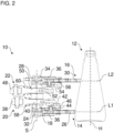
- the Figures 1 and 2 show a clamping device 10 in different views.
- the clamping device 10 holds a container 12.
- the container 12 preferably has a container body with different outer circumferences along its length or height.
- the container 12 can preferably be designed as a so-called contour container.
- the container 12 can nevertheless be held securely by the clamping device 10, as described below by way of example.
- the clamping device 10 has a first clamp arm pair 14 and a second clamp arm pair 16.
- the clamping device 10 can optionally have a clamp carrier 18, a first actuating device 20 and/or a second actuating device 22.
- the clamping device 10 is designed as a double clamping device with the two clamping arm pairs 14, 16.
- the clamping device it is also possible for the clamping device to have additional clamping arm pairs (not shown).
- the clamping device 10 can be designed as a multiple clamping device with several clamping arm pairs 14, 16.
- the first clamp arm pair 14 can have two first clamp arms 24, 26.
- the second clamp arm pair 16 can have two second clamp arms 28, 30.
- the clamp arms 24 and 26 (or 28 and 30) can be formed separately, as shown in the Figures 1 and 2 It is possible that the clamp arms 24 and 26 (or 28 and 30) are formed integrally with one another.
- the second pair of clamp arms 16 can be designed to be substantially identical in construction and/or functionally identical to the first pair of clamp arms 14.
- the first pair of clamp arms 14 and the second pair of clamp arms 16 are designed to be substantially mirror-symmetrical with respect to a central longitudinal plane of the clamping device 10 or with respect to a horizontal plane (in the assembled state).
- the central longitudinal plane divides the clamping device 10 at half height and runs parallel to the longitudinal axes L1, L2 of the pairs of clamp arms 14, 16.
- the clamp arm pairs 14, 16 are each pivotably mounted.
- the pivotable mounting is preferably arranged at one end of the clamp arm pairs 14, 16 opposite the container 12 or the free ends of the clamp arm pairs 14, 16.
- the clamp arm pairs 14, 16 can preferably be pivotable coaxially to one another or can be pivotable about a common pivot axis S.
- first clamp arms 24, 26 can preferably be pivoted in opposite directions to one another.
- the second clamp arms 28, 30 can be pivoted in opposite directions to one another.
- the first clamp arms 24, 26 can be pivoted towards one another until they rest against the container 12, and the second clamp arms 28, 30 can be pivoted towards one another until they rest against the container 12.
- the first clamp arms 24, 26 can be pivoted away from one another and the second clamp arms 28, 30 can be pivoted away from one another.
- the first and second pairs of clamp arms 14, 16 are arranged to hold the same container 12 at the same time.
- the first and second pairs of clamp arms 14, 16 are arranged vertically offset from one another, for example, with respect to a vertical axis H of the container 12.
- the second pair of clamp arms 16 (the two second clamp arms 28, 30) is arranged above the first pair of clamp arms 14 (the two first clamp arms 24, 26), as shown in the Figures 1 and 2 is shown, or vice versa.
- the first pair of clamp arms 14 can hold the container 12 at a first outer peripheral section or casing section 12A.
- the second pair of clamp arms 16 can hold the container 12 at a second outer peripheral section or casing section 12B.
- the outer peripheral sections 12A, 12B are preferably each circumferential or self-contained.
- the outer peripheral sections 12A and 12B are arranged offset from one another with respect to the vertical axis H of the container 12. For example, the second outer peripheral section 12B is arranged above the first outer peripheral section 12A, as shown in the Figures 1 and 2 is shown, or vice versa.
- the outer peripheral sections 12A and 12B can differ from one another in terms of shape and/or size or length.
- the shape of the outer peripheral sections 12A and 12B is the same, namely circular in terms of a cross section or frustoconical in terms of the vertical axis H.
- the outer peripheral sections 12A and 12B differ in size.
- the second outer peripheral section 12B has a smaller circumference and a smaller diameter than the first outer peripheral section 12A.
- the container 12 can be held at the front or the container 12 facing sections of the clamp arm pairs 14, 16.
- the container 12 can be held between the free ends of the first clamp arms 24, 26 and between the free ends of the second clamp arms 28, 30.
- the first clamp arms 24, 26 and the second clamp arms 28, 30 can grip the container 12 at their free ends.
- the first clamp arms 24, 26 and the second clamp arms 28, 30 can grip the container 12 between their free ends by applying a Clamp holding force.
- the holding force can be caused, for example, by a pre-tension acting on the first pair of clamp arms 14 and a pre-tension acting on the second pair of clamp arms 16.
- the two clamp arm pairs 14, 16 can be pivoted independently or decoupled from one another.
- the first clamp arm pair 14 can be pivoted without the second clamp arm pair 16 pivoting along with it, and vice versa.
- a pivoting movement of the first clamp arm pair 14 against the second outer peripheral section 12B does not influence a pivoting movement of the first clamp arm pair 14 against the first outer peripheral section 12A, and vice versa.
- the pivoting movement of the second clamp arm pair 16 can, for example, continue while the first clamp arm pair 14 is already resting against the first outer peripheral section 12A, and vice versa (e.g. depending on a shape and/or size of the outer peripheral sections 12A, 12B).
- the clamp arm pairs 14, 16 can begin the pivoting movements simultaneously (e.g.
- the clamp arm pairs 14, 16 are no longer actuated) and/or end them one after the other (e.g. at the time of contact with the container 12), preferably under the effect of a pre-tension of the clamp arm pairs 14 and 16.
- the first clamp arms 24, 26 pivot towards one another.
- the second clamp arms 28, 30 pivot towards one another.
- a release pivoting movement of the second clamp arm pair 16 away from the second outer peripheral portion 12B does not affect a release pivoting movement of the first clamp arm pair 14 away from the first outer peripheral portion 12A, and vice versa.
- the release pivoting movement of the first clamp arm pair 14 can, for example, begin before the release pivoting movement of the second clamp arm pair 16 begins, and vice versa (e.g. depending on a shape and/or size of the outer peripheral portions 12A, 12B).
- the clamp arm pairs 14, 16 can end the release pivoting movements simultaneously, preferably under the effect of an actuation of the clamp arm pairs 14 and 16.
- the first clamp arms 24, 26 pivot away from one another.
- the second clamp arms 28, 30 pivot away from one another.
- the clamp arm pairs 14, 16 can each extend along a longitudinal axis L1 or L2.
- the longitudinal axes L1, L2 can run essentially parallel to one another.
- the longitudinal axes L1, L2 can run essentially perpendicular to the vertical axis H.
- the longitudinal axes L1, L2 can run essentially perpendicular to the pivot axis S. In the assembled state, the longitudinal axes L1, L2 can run essentially parallel to a horizontal plane.
- the clamp arm pairs 14, 16 can be pivotally mounted on the clamp carrier 18.
- the clamp arm pairs 14, 16 can be pivotally mounted on the clamp carrier 18 on opposite sides of the clamp carrier 18.
- the clamp carrier 18 can be arranged between the clamp arm pairs 14, 16, preferably with respect to a vertical axis of the clamping device 10.
- the clamp carrier 18 can carry the clamp arm pairs 14, 16.
- the clamp carrier 18 is preferably designed in block form.
- the clamp arm carrier preferably extends longitudinally along the pivot axis S and/or parallel to the vertical axis H.
- the clamp arm pairs 14, 16 can each be pivotally mounted by means of a preferably elongated pivot pin 32, 34 of the clamp carrier 18.
- the clamp arms 24, 26, 28, 30 can each have a through hole, e.g. at an end of the respective clamp arm 24, 26, 28, 30 opposite the free end.
- the pivot pins 32, 34 can extend through the through holes. It is possible for sliding bushes to be arranged between the pivot pins 32, 34 and the through holes.
- the pivot pins 32, 34 can extend coaxially to the pivot axis S.
- the pivot pins 32, 34 can extend parallel to the vertical axis H.
- the pivot pins 32, 34 can be arranged on opposite sides of the clamp carrier 18.
- the pivot pin 34 can be arranged on an upper side of the clamp carrier 18.
- the pivot pin 32 can be arranged on an underside of the clamp carrier 18.
- the first clamp arms 24, 26 can be placed one above the other on the pivot pin 32.
- the second clamp arms 28, 30 can be placed one above the other on the pivot pin 34.
- the first clamp arms 24, 26 can be secured axially on the pivot pin 32.
- the second clamp arms 28, 30 can be secured axially on the pivot pin 34.
- the respective axial securing can be carried out, for example, by means of a screw head of a screw that is screwed into a (e.g. central) hole in the pivot pin 32, 34, preferably coaxially to the pivot axis S.
- the clamp arm pairs 14, 16 Adjacent to the pivotable mounting to the clamp carrier 18, the clamp arm pairs 14, 16 can be reinforced. In detail, a material thickness of the clamp arms 24, 26, 28, 30 adjacent to the pivotable mounting can be increased.
- the clamp arms 24, 26, 28, 30 can, for example, have reinforcing ribs 36 adjacent to the pivotable mounting.
- the reinforcing ribs 36 can, for example, be designed as wall elements on an upper side and/or a lower side of the clamp arms 24, 26, 28, 30.
- the wall elements can be ring-shaped or circumferential structures.
- the reinforcing ribs 36 can be arranged in the section of the clamp arms 24, 26, 28, 30 that is opposite the free ends of the clamp arms 24, 26, 28, 30.
- the reinforcing ribs 36 can taper towards the free ends of the clamp arms 24, 26, 28, 30.
- clamp arms 24 and 26 as well as 28 and 30 can have stops facing each other in their middle sections with respect to the longitudinal axes L1 and L2.
- the clamp arms 24 and 26 as well as 28 and 30 can rest against each other on the stops in the closed position when they are not holding a container 12.
- the clamp arm pairs 14, 16 can be pivoted by the actuating devices 20, 22 about the pivot pins 32, 34 or the pivot axis S.
- the actuating devices 20, 22 can preferably each be designed as roller controls.
- the actuating devices 20, 22 can preferably pivot the clamp arm pairs 14, 16 to release the container 12 for opening.
- the actuating devices 20, 22 are preferably of identical construction and/or function.
- the first actuating device 20 and the second actuating device 22 are essentially mirror-symmetrical with respect to the central longitudinal plane of the clamping device 10 or with respect to a horizontal plane (in the assembled state).
- the actuating devices 20, 22 can be arranged one above the other.
- the actuating devices 20, 22 can be arranged between the first clamp arm pair 14 and the second clamp arm pair 16, preferably with respect to a vertical axis of the clamping device 10.
- the first actuating device 20 can be arranged partially on an upper side of the first clamp arm pair 14.
- the second actuating device 22 can be arranged partially on an underside of the second clamp arm pair 16.
- the actuating devices 20, 22 can extend substantially parallel to the longitudinal axes L1, L2 of the clamp arm pairs 14, 16.
- the actuating devices 20, 22 can be carried by the clamp carrier 18.
- the actuating devices 20, 22 can extend through the clamp carrier 18, preferably from a rear side or a side of the clamp carrier 18 facing away from the container 12 to a front side or a side of the clamp carrier 18 facing the container 12.
- the actuating devices 20, 22 are themselves decoupled from each other so that they can move independently of each other.
- the first actuating device 20 can move without the second actuating device 22 moving, and vice versa.
- the first actuating device 20 can be connected to the first clamp arms 24, 26 in a section between the free ends and the pivot bearing of the first clamp arms 24, 26, preferably in middle sections of the first clamp arms 24, 26 with respect to the longitudinal axis L1.
- the second actuating device 22 can be connected to the second clamp arms 28, 30 in a section between the free ends and the pivot bearing of the second clamp arms 28, 30, preferably in middle sections of the second clamp arms 28, 30 with respect to the longitudinal axis L2.
- the first actuating device 20 can preferably have an input element 38, a transmission element 40, a coupling element 42 and two pivot arms 44, 46. It is possible that the components 38, 40, 42, 44, 46 are at least partially integrated into one another.
- the second actuating device 22 can be constructed and function like the first actuating device 20 with an input element 48, a transmission element 50, a coupling element 52 and two pivot arms 54, 56. The following detailed explanations of the first actuating device 20 can therefore, mutatis mutandis, apply accordingly to the second actuating device 22.
- the input element 38 is carried on the transmission element 40, preferably at the end.
- the input element 38 can be arranged on a side of the clamp carrier 18 facing away from the container 12 or on a rear side of the clamp device 10 or the clamp carrier 18.
- the input element 38 can receive a mechanical input.
- the input element can, for example, be designed as a rotatable roller, as in Figure 1 and 2 is shown, or be designed as a sliding shoe.
- the input element 38 can be acted upon by a guide curve or control curve, for example.
- the input element 38 can transmit the received input to the transmission element 40.
- the transmission element 40 is slidably mounted in the clamp carrier 18, preferably in a sliding bush.
- the transmission element 40 can be elongated, preferably rod-shaped.
- the transmission element 40 can be displaced in response to the input, preferably parallel to the longitudinal axes L1, L2 and/or perpendicular to the pivot axis S.
- the transmission element 40 carries the coupling element 42, preferably at an end opposite the input element 38.
- the coupling element 42 is attached to the transmission element 40, preferably on the front side.
- the coupling element 42 can be attached to the transmission element 40 by means of a screw. If the transmission element 40 is moved, the coupling element 42 The coupling element 42 couples the transmission element 40 with the swivel arms 44, 46.
- the pivot arm 44 connects the first clamp arm 24 to the coupling element 42.
- the pivot arm 44 is pivotally connected to the coupling element 42 at one end, e.g. by means of a bolt or pivot pin.
- the pivot arm 44 is pivotally connected to the clamp arm 24 at an opposite end, e.g. by means of a bolt or pivot pin.
- the pivot arm 46 connects the first clamp arm 26 to the coupling element 42.
- the pivot arm 46 is pivotally connected to the coupling element 42 at one end, e.g. by means of a bolt or pivot pin.
- the pivot arm 46 is pivotally connected to the first clamp arm 26 at an opposite end, e.g. by means of a bolt or pivot pin.
- the pivot arms 44, 46 are preferably arranged in a V-shape and/or one above the other (e.g. with respect to the vertical axis).
- the pivot arms 44, 46 are preferably pivotable coaxially with respect to the coupling element 42.
- parallel pivot axes for the pivot arms 44, 46 with respect to the coupling element 42 are also possible, for example.
- the pivot arms 44, 46 are preferably arranged between the coupling element 42 or the transmission element 40 and the first pair of clamp arms 14 with respect to a vertical axis of the clamping device 10.
- displacement of the input member 48 toward the container 12 causes displacement of the transmission member 40 toward the container 12.
- displacement of the transmission member 40 toward the container 12 causes displacement of the coupling member 42 toward the container 12.
- Displacement of the coupling member 42 toward the container 12 causes displacement of the ends of the pivot arms 44, 46 pivotally connected to the coupling element 42 toward the container 12.
- Displacement of the ends of the pivot arms 44, 46 pivotally connected to the coupling element 42 causes pivoting of the pivot arms 44, 46 at those ends since the pivot arms 44, 46 are supported on the first clamp arms 24, 26.
- the pivoting of the pivot arms 44, 46 causes a pivoting of the first clamp arms 24, 26, preferably a pivoting or opening of the first clamp arms 24, 26 to release the container 12.
- the clamp arm pairs 14, 16 can be subjected to a pre-tension towards closing or pivoting in.
- the clamping device 10 can have a first pre-tensioning element 58 for the first clamp arm pair 14 and a second pre-tensioning element 60 for the second clamp arm pair 16.
- the prestressing elements 58, 60 can be arranged and designed separately from the clamp arm pairs 14, 16, as in Figure 1 and 2 It is possible that the pre-tensioning elements 58, 60 are arranged directly on the clamp arm pairs 14, 16 and/or are formed integrally with the respective clamp arm pair 14 or 16.
- the pre-tensioning elements can be substantially U-shaped and/or can encompass the respective clamp arm pair 13 or 16 in a horizontal plane.
- the pre-tensioning elements 58, 60 can be arranged one above the other.
- the pre-tensioning elements 58, 60 can extend parallel to one another and/or parallel to the longitudinal axes L1, L2.
- the pre-tensioning elements 58, 60 can be arranged on a side of the clamp carrier 18 facing away from the container 12.
- the pre-tensioning elements 58, 60 can be supported on the clamp carrier 18, preferably on a side of the clamp carrier 18 facing away from the container 12.
- the pre-tensioning element 58 can be supported on the transmission element 40, preferably on an end section of the transmission element 40 carrying the input element 38.
- the pre-tensioning element 60 can be supported on the transmission element 50, preferably on an end section of the transmission element 50 carrying the input element 48.
- the transmission element 40 can extend through the preloading element 58 or the preloading element 58 can surround a portion of the transmission element 40.
- the transmission element 50 can extend through the preloading element 60 or the preloading element 60 can surround a portion of the transmission element 50.
- the preloading elements 58, 60 are designed as coil springs.
- the pre-tensioning elements 58, 60 can pre-tension the actuating devices 20, 22 in the direction away from the container 12 to close the clamp arm pairs 14, 16.
- the pre-tensioning elements 58 and 60 can pre-tension the transmission elements 40 and 50 in the direction away from the container 12.
- the clamp arms 24, 26 and 28, 30 are pivoted or pivoted towards each other.
- a holding force can be applied to the container 12 so that the container 12 can be held force-fittingly between the clamp arms 24, 26 and 28, 30.
- the preload caused by the preload elements 58, 60 for opening the clamp arm pairs 14 and 16 can be overcome.
- the clamping device 10 can have a fastening device 62.
- the fastening device 62 is designed to fasten the clamping device 10 to a transport device, e.g. a transport carousel, e.g. by means of a screw connection.
- the fastening device 62 can have at least one positioning element.
- the positioning element can position the clamping device 10 correctly on the transport device when it is fastened to the transport device.
- the positioning element can be designed as a positioning pin, for example.
- the fastening device 62 can be fastened to the clamp carrier 18, e.g. on a rear side, top side and/or bottom side of the clamp carrier 18.
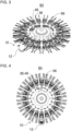
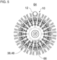
- FIGS. 3 to 5 show different views of a transport device 64 with several clamping devices 10. For the sake of clarity, only one container 12 is shown. The clamping devices 10 are nevertheless all shown as if they were each carrying a container 12.
- the transport device 64 is designed as a rotatable transport carousel.
- the clamping devices 10 are arranged, preferably evenly, around a circumference of the transport device 64.
- the transport device 64 can be designed as a so-called clamping star. Due to the double-decker nature of the clamping devices 10, the clamping star is designed as a double-decker clamping star.
- the transport device 64 has a guide contour 66.
- the input elements 38, 48 can follow the common guide contour 66.
- the temporary operative connection between the guide contour 66 and the clamp arm pairs 14 and 16 by means of the actuating devices 20, 22 causes the clamp arm pairs 14, 16 to open or pivot open.
- the container 12 is released.
- the input element 48 would first come into contact with the guide contour 66, since it protrudes further to the rear in a direction parallel to the longitudinal axes L1, L2 than the input element 38.
- the input element 38 comes into contact with the guide contour 66.
- the first pair of clamp arms 14 begins to open, while the second pair of clamp arms 16 opens further. The contact can preferably take place at a time when the pairs of clamp arms 14, 16 are equally open (closed).
- the invention is not limited to the preferred embodiments described above. Rather, a large number of variants and modifications are possible which also make use of the inventive concept and therefore fall within the scope of protection.
- the invention also claims protection for the subject matter and the features of the subclaims independently of the claims referred to.
- the individual features of independent claim 1 are each disclosed independently of one another.
- the features of the subclaims are also disclosed independently of all features of independent claim 1 and, for example, independently of the features relating to the presence and/or configuration of the first pair of clamp arms and/or the second pair of clamp arms of independent claim 1.
Landscapes
- Engineering & Computer Science (AREA)
- Mechanical Engineering (AREA)
- Specific Conveyance Elements (AREA)
- Supplying Of Containers To The Packaging Station (AREA)
- Filling Of Jars Or Cans And Processes For Cleaning And Sealing Jars (AREA)
- Load-Engaging Elements For Cranes (AREA)
Applications Claiming Priority (2)
| Application Number | Priority Date | Filing Date | Title |
|---|---|---|---|
| DE102021107294.8A DE102021107294A1 (de) | 2021-03-24 | 2021-03-24 | Klammervorrichtung und Verfahren zum Transportieren eines Behälters |
| EP22163830.7A EP4067270B1 (fr) | 2021-03-24 | 2022-03-23 | Dispositif de serrage et procédé de transport d'un récipient |
Related Parent Applications (2)
| Application Number | Title | Priority Date | Filing Date |
|---|---|---|---|
| EP22163830.7A Division EP4067270B1 (fr) | 2021-03-24 | 2022-03-23 | Dispositif de serrage et procédé de transport d'un récipient |
| EP22163830.7A Division-Into EP4067270B1 (fr) | 2021-03-24 | 2022-03-23 | Dispositif de serrage et procédé de transport d'un récipient |
Publications (2)
| Publication Number | Publication Date |
|---|---|
| EP4477331A2 true EP4477331A2 (fr) | 2024-12-18 |
| EP4477331A3 EP4477331A3 (fr) | 2025-03-12 |
Family
ID=80930139
Family Applications (2)
| Application Number | Title | Priority Date | Filing Date |
|---|---|---|---|
| EP24201833.1A Pending EP4477331A3 (fr) | 2021-03-24 | 2022-03-23 | Dispositif de serrage et procédé de transport d'un récipient |
| EP22163830.7A Active EP4067270B1 (fr) | 2021-03-24 | 2022-03-23 | Dispositif de serrage et procédé de transport d'un récipient |
Family Applications After (1)
| Application Number | Title | Priority Date | Filing Date |
|---|---|---|---|
| EP22163830.7A Active EP4067270B1 (fr) | 2021-03-24 | 2022-03-23 | Dispositif de serrage et procédé de transport d'un récipient |
Country Status (4)
| Country | Link |
|---|---|
| US (1) | US20220306401A1 (fr) |
| EP (2) | EP4477331A3 (fr) |
| CN (1) | CN115123807B (fr) |
| DE (1) | DE102021107294A1 (fr) |
Families Citing this family (7)
| Publication number | Priority date | Publication date | Assignee | Title |
|---|---|---|---|---|
| IT202000014836A1 (it) * | 2020-06-22 | 2021-12-22 | Arol Spa | Dispositivo di manipolazione di contenitori per impianti di tappatura |
| USD976095S1 (en) * | 2021-05-17 | 2023-01-24 | Elesa S.P.A. | Clamp |
| DE102021129518A1 (de) | 2021-11-12 | 2023-05-17 | Krones Aktiengesellschaft | Klammervorrichtung und Transportvorrichtung |
| USD1101548S1 (en) * | 2022-12-05 | 2025-11-11 | Elesa S.P.A. | Clamp |
| DE102023102680A1 (de) | 2023-02-03 | 2024-08-08 | Krones Aktiengesellschaft | Behälterbehandlungsanlage mit verbesserter Zuführung |
| CN116772093A (zh) * | 2023-06-06 | 2023-09-19 | 宁波大通亨利机械制造有限公司 | 一种罐体自动罐装装置 |
| EP4484342A1 (fr) * | 2023-06-30 | 2025-01-01 | Tyrolon-Schulnig GmbH | Dispositif de préhension et dispositif de transport |
Citations (1)
| Publication number | Priority date | Publication date | Assignee | Title |
|---|---|---|---|---|
| DE102005014838A1 (de) | 2005-03-30 | 2006-10-05 | Krones Ag | Klammer zum Halten von Gefäßen |
Family Cites Families (16)
| Publication number | Priority date | Publication date | Assignee | Title |
|---|---|---|---|---|
| DE19740892A1 (de) * | 1997-09-17 | 1999-03-25 | Kettner Gmbh | Transportstern für Gefäße |
| DE20305988U1 (de) * | 2003-04-14 | 2003-07-03 | Tyrolon-Schulnig Ges.M.B.H., Hochfilzen | Transportstern |
| EP2774876B1 (fr) * | 2013-03-06 | 2016-03-02 | Tyrolon-Schulnig GmbH | Dispositif de préhension destiné à saisir et à maintenir des bouteilles et dispositif de transport doté d'un tel dispositif de préhension |
| DE102013113292A1 (de) * | 2013-12-02 | 2015-06-18 | Khs Gmbh | Transportstern mit verstellbaren Sterntaschen |
| DE102014116259A1 (de) * | 2014-11-07 | 2016-05-12 | Khs Gmbh | Transportstern für den Transport von Behältern |
| EP3165482A1 (fr) | 2015-11-09 | 2017-05-10 | Liese GmbH | Poignee ayant une face arriere accessible pour un dispositif de manipulation de recipient, pince de prehension, bras de prehension et systeme de transport en etoile |
| WO2018108370A1 (fr) * | 2016-12-13 | 2018-06-21 | Tyrolon-Schulnig Gmbh | Dispositif support modulaire pour au moins une paire de bras préhenseurs et son procédé de montage |
| DE102017105016B3 (de) * | 2017-03-09 | 2018-02-22 | Tyrolon-Schulnig Gmbh | Lagervorrichtung |
| US10865055B2 (en) * | 2017-01-10 | 2020-12-15 | Tyrolon-Schulnig Gmbh | Gripper arm for containers and gripper device having such gripper arms |
| DE102017105015B4 (de) * | 2017-03-09 | 2019-10-10 | Tyrolon-Schulnig Gmbh | Greif- und Transportvorrichtung |
| DE102017108928B4 (de) * | 2017-04-26 | 2022-10-27 | Khs Gmbh | Behältergreifer |
| DE102017129506A1 (de) * | 2017-12-11 | 2019-06-13 | Krones Ag | Aktive Klammervorrichtung |
| DE102018104112A1 (de) | 2018-02-23 | 2019-08-29 | Khs Gmbh | Greifer für ein Behältertransportsystem |
| DE102018113301A1 (de) * | 2018-06-05 | 2019-12-05 | Krones Ag | Vorrichtung zum Transportieren von Behältern |
| EP3613683B1 (fr) * | 2018-08-22 | 2022-08-03 | Kematec Kellereitechnik GmbH | Unité de préhension |
| DE102019113653A1 (de) * | 2019-05-22 | 2020-11-26 | Krones Ag | Vorrichtung zum Halten eines Behälters und Verschließvorrichtung |
-
2021
- 2021-03-24 DE DE102021107294.8A patent/DE102021107294A1/de active Pending
-
2022
- 2022-03-23 EP EP24201833.1A patent/EP4477331A3/fr active Pending
- 2022-03-23 EP EP22163830.7A patent/EP4067270B1/fr active Active
- 2022-03-24 CN CN202210302907.8A patent/CN115123807B/zh active Active
- 2022-03-24 US US17/703,549 patent/US20220306401A1/en active Pending
Patent Citations (1)
| Publication number | Priority date | Publication date | Assignee | Title |
|---|---|---|---|---|
| DE102005014838A1 (de) | 2005-03-30 | 2006-10-05 | Krones Ag | Klammer zum Halten von Gefäßen |
Also Published As
| Publication number | Publication date |
|---|---|
| DE102021107294A1 (de) | 2022-09-29 |
| EP4477331A3 (fr) | 2025-03-12 |
| EP4067270B1 (fr) | 2024-10-30 |
| CN115123807A (zh) | 2022-09-30 |
| EP4067270C0 (fr) | 2024-10-30 |
| US20220306401A1 (en) | 2022-09-29 |
| EP4067270A1 (fr) | 2022-10-05 |
| CN115123807B (zh) | 2025-04-11 |
Similar Documents
| Publication | Publication Date | Title |
|---|---|---|
| EP4067270B1 (fr) | Dispositif de serrage et procédé de transport d'un récipient | |
| DE2264445C3 (de) | Greif- und Haltevorrichtung an einer Fördereinrichtung für Behälter | |
| EP2774876B1 (fr) | Dispositif de préhension destiné à saisir et à maintenir des bouteilles et dispositif de transport doté d'un tel dispositif de préhension | |
| EP3919419B1 (fr) | Dispositif de maintien d'un récipient et dispositif de manutention des récipients | |
| EP2295352A2 (fr) | Dispositif de prise pour tenir et déplacer des articles | |
| EP0795500A2 (fr) | Roue à étoile pour récipients | |
| EP3747806B1 (fr) | Dispositif d'ajustement d'une largeur de guidage d'un dispositif de transport | |
| DE3622521A1 (de) | Sitzaufhaengungseinrichtung | |
| DE10001580B4 (de) | Greifervorrichtung | |
| EP3912939A1 (fr) | Dispositif de serrage et dispositif de manutention de conteneurs | |
| EP4186831A1 (fr) | Dispositif de serrage pour maintenir un récipient | |
| EP3907161B1 (fr) | Dispositif de collier de serrage passif | |
| EP3964461B1 (fr) | Dispositif de serrage permettant de maintenir un récipient et dispositif de manutention de récipients | |
| EP2928798A1 (fr) | Dispositif de blocage de pivotement pour élément de préhension de bouteille | |
| DE102020131105A1 (de) | Vorrichtung zum linearen Transportieren von Behältern | |
| DE4221525C2 (de) | Vorrichtung zum Verbinden zylindrischer Bauteile | |
| DE19536692A1 (de) | Transportstern für Gefäße | |
| EP4119473A1 (fr) | Pince de récipient pour différents types de récipients | |
| EP3816075B1 (fr) | Bras de préhension, dispositif de préhension ainsi que dispositif de transport destiné à la préhension, le maintien et le guidage, en particulier des récipients de type bouteille | |
| DE29501897U1 (de) | Transportstern für Gefäße | |
| DE102022108164A1 (de) | Kettenführung für Behälter | |
| EP0999153A1 (fr) | Roue à étoile de transfert pour transporter de conteneurs | |
| DE20020456U1 (de) | Übergabestern zum Transportieren von Gefäßen | |
| EP4484342A1 (fr) | Dispositif de préhension et dispositif de transport | |
| EP4335794A1 (fr) | Dispositif de suivi d'une courbe d'actionnement |
Legal Events
| Date | Code | Title | Description |
|---|---|---|---|
| PUAI | Public reference made under article 153(3) epc to a published international application that has entered the european phase |
Free format text: ORIGINAL CODE: 0009012 |
|
| STAA | Information on the status of an ep patent application or granted ep patent |
Free format text: STATUS: THE APPLICATION HAS BEEN PUBLISHED |
|
| AC | Divisional application: reference to earlier application |
Ref document number: 4067270 Country of ref document: EP Kind code of ref document: P |
|
| AK | Designated contracting states |
Kind code of ref document: A2 Designated state(s): AL AT BE BG CH CY CZ DE DK EE ES FI FR GB GR HR HU IE IS IT LI LT LU LV MC MK MT NL NO PL PT RO RS SE SI SK SM TR |
|
| REG | Reference to a national code |
Ref country code: DE Ref legal event code: R079 Free format text: PREVIOUS MAIN CLASS: B08B0009420000 Ipc: B65G0047860000 |
|
| PUAL | Search report despatched |
Free format text: ORIGINAL CODE: 0009013 |
|
| AK | Designated contracting states |
Kind code of ref document: A3 Designated state(s): AL AT BE BG CH CY CZ DE DK EE ES FI FR GB GR HR HU IE IS IT LI LT LU LV MC MK MT NL NO PL PT RO RS SE SI SK SM TR |
|
| RIC1 | Information provided on ipc code assigned before grant |
Ipc: B08B 9/42 20060101ALI20250203BHEP Ipc: B65G 47/86 20060101AFI20250203BHEP |
|
| STAA | Information on the status of an ep patent application or granted ep patent |
Free format text: STATUS: REQUEST FOR EXAMINATION WAS MADE |
|
| 17P | Request for examination filed |
Effective date: 20250912 |