EP4475427A1 - Motorsteuerungsvorrichtung und elektrische servolenkvorrichtung - Google Patents
Motorsteuerungsvorrichtung und elektrische servolenkvorrichtung Download PDFInfo
- Publication number
- EP4475427A1 EP4475427A1 EP23922896.8A EP23922896A EP4475427A1 EP 4475427 A1 EP4475427 A1 EP 4475427A1 EP 23922896 A EP23922896 A EP 23922896A EP 4475427 A1 EP4475427 A1 EP 4475427A1
- Authority
- EP
- European Patent Office
- Prior art keywords
- phase
- value
- voltage command
- duty ratio
- command value
- Prior art date
- Legal status (The legal status is an assumption and is not a legal conclusion. Google has not performed a legal analysis and makes no representation as to the accuracy of the status listed.)
- Pending
Links
Images


Classifications
-
- H—ELECTRICITY
- H02—GENERATION; CONVERSION OR DISTRIBUTION OF ELECTRIC POWER
- H02P—CONTROL OR REGULATION OF ELECTRIC MOTORS, ELECTRIC GENERATORS OR DYNAMO-ELECTRIC CONVERTERS; CONTROLLING TRANSFORMERS, REACTORS OR CHOKE COILS
- H02P27/00—Arrangements or methods for the control of AC motors characterised by the kind of supply voltage
- H02P27/04—Arrangements or methods for the control of AC motors characterised by the kind of supply voltage using variable-frequency supply voltage, e.g. inverter or converter supply voltage
- H02P27/06—Arrangements or methods for the control of AC motors characterised by the kind of supply voltage using variable-frequency supply voltage, e.g. inverter or converter supply voltage using DC to AC converters or inverters
- H02P27/08—Arrangements or methods for the control of AC motors characterised by the kind of supply voltage using variable-frequency supply voltage, e.g. inverter or converter supply voltage using DC to AC converters or inverters with pulse width modulation
-
- H—ELECTRICITY
- H02—GENERATION; CONVERSION OR DISTRIBUTION OF ELECTRIC POWER
- H02P—CONTROL OR REGULATION OF ELECTRIC MOTORS, ELECTRIC GENERATORS OR DYNAMO-ELECTRIC CONVERTERS; CONTROLLING TRANSFORMERS, REACTORS OR CHOKE COILS
- H02P21/00—Arrangements or methods for the control of electric machines by vector control, e.g. by control of field orientation
- H02P21/22—Current control, e.g. using a current control loop
-
- B—PERFORMING OPERATIONS; TRANSPORTING
- B62—LAND VEHICLES FOR TRAVELLING OTHERWISE THAN ON RAILS
- B62D—MOTOR VEHICLES; TRAILERS
- B62D5/00—Power-assisted or power-driven steering
- B62D5/04—Power-assisted or power-driven steering electrical, e.g. using an electric servo-motor connected to, or forming part of, the steering gear
- B62D5/0457—Power-assisted or power-driven steering electrical, e.g. using an electric servo-motor connected to, or forming part of, the steering gear characterised by control features of the drive means as such
- B62D5/046—Controlling the motor
Definitions
- the present disclosure relates to a motor control device and an electric power steering device.
- a motor control device described in PTL 1 is configured to perform measurement of phase currents in a first measurement period when a maximum target duty ratio among target duty ratios of PWM signals to drive respective switching elements in a bridge circuit is less than or equal to a first threshold value or when the maximum target duty ratio is greater than the first threshold value and a second-largest target duty ratio is greater than or equal to a second threshold value.
- a motor control device configured to control a polyphase motor having three or more phases and includes: (b) a bridge circuit configured by connecting in parallel phase circuits each formed corresponding to one of phases of the polyphase motor and including in series a high-potential-side switching element, a low-potential-side switching element, and a shunt resistor arranged on a low potential side of the low-potential-side switching element; (c) a phase current measurement unit configured to measure phase currents flowing through the shunt resistors in a first measurement period or a second measurement period, the second measurement period being started later than the first measurement period; (d) a PWM signal generation unit configured to, with respect to each phase of the polyphase motor, calculate, based on the phase current, a target duty ratio, the target duty ratio being a target duty ratio of a PWM signal to drive the high-potential-side switching element and the low-potential-side switching
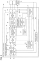
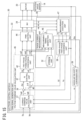
- FIG. 1 is a diagram illustrative of an overall configuration of an electric power steering device 100 according to a first embodiment.
- a steering shaft 2 of a steering wheel 1 is connected to steered wheels 8L and 8R by way of a reduction gear 3 that constitutes a speed reduction mechanism, universal joints 4a and 4b, a pinion rack mechanism 5, and tie rods 6a and 6b and further via hub units 7a and 7b.
- a torque sensor 9 configured to detect steering torque Th of a driver and a steering angle sensor 10 configured to detect a steering angle ⁇ h of the steering wheel 1 are attached.
- a motor 20 configured to provide steering assist force is connected to the steering shaft 2 via the reduction gear 3.
- a polyphase motor having three or more phases can be employed. In the following description, a case where a three-phase motor is used is described.
- the number of motors 20 may be configured to be two or more.
- the motor 20 may also be configured to include a plurality of sets of windings of three or more phases.
- an electronic control unit 30 (in a broad sense, the "motor control device") configured to control the electric power steering device 100, power is supplied from a battery 11 and an ignition key signal is also input by way of an ignition switch 12.
- the electronic control unit 30 performs calculation of current command values of an assist control command, based on steering torque Th detected by the torque sensor 9, a steering angle ⁇ h detected by the steering angle sensor 10, and vehicle speed Vh detected by a vehicle speed sensor 13 and controls currents (for example, phase currents ia, ib, and ic of respective phases A, B, and C) to be supplied to the motor 20 by voltage command values obtained by performing compensation and the like on the current command values. That is, it can be said that the motor 20 is controlled by the electronic control unit 30 and provides a steering system of a vehicle with steering assist force.
- a detection method of a turning angle of the steered wheels 8L and 8R for example, a method for detecting the turning angle based on a displacement amount of the rack 5b can be employed.
- Measurement of the motor angle ⁇ m is performed in a first measurement period Ts 1 that is a measurement period of the phase currents ia, ib, and ic.
- the electronic control unit 30 includes, for example, a computer including a processor 31 and peripheral components, such as a storage unit 32.
- a processor 31 for example, a central processing unit (CPU) or a micro-processing unit (MPU) can be employed.
- the storage unit 32 for example, a semiconductor storage unit, a magnetic storage unit, or an optical storage unit can be employed. Examples of the storage unit 32 include a memory, such as a ROM and a RAM, that is used as registers, a cache memory, and a main storage. Functions of the electronic control unit 30, which will be described below, are achieved by, for example, the processor 31 of the electronic control unit 30 executing computer programs stored in the storage unit 32.
- the storage unit 32 stores various types of data necessary for executing computer programs, such as a first threshold value TH 1 and a second threshold value TH 2 that are used in timing generation processing, which will be described later.
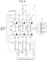
- the PWM signal generation unit 33 calculates, with respect to the respective phases A, B, and C of the motor 20, target duty ratios Da, Db, and Dc of PWM signals, based on the phase currents ia, ib, and ic, and outputs PWM signals having the calculated target duty ratios Da, Db, and Dc to gates of high-potential-side switching elements Qah, Qbh, and Qch and low-potential-side switching elements Qal, Qbl, and Qcl, respectively.
- the angular velocity conversion unit 36 calculates rotational angular velocity ⁇ of the motor 20, based on the motor angle ⁇ m acquired from the rotation angle sensor 14.
- the rotational angular velocity ⁇ is input to the current command value calculation unit 37.
- the current command value calculation unit 37 calculates a q-axis current command value Iq0 and a d-axis current command value Id0 that are required to be flowed through the motor 20, based on the steering torque Th acquired from the torque sensor 9, the vehicle speed Vh, the motor angle ⁇ m, and the rotational angular velocity ⁇ of the motor 20.
- the q-axis current command value Iq0 is input to the subtracter 39.
- the d-axis current command value Id0 is input to the subtracter 40.
- the three-phase/two-phase conversion unit 38 converts the phase currents ia, ib, and ic of the phases A, B, and C that are acquired from the phase current measurement unit 35 to currents id and iq of two axes d and q.
- the q-axis current iq is input to the subtracter 39.
- the d-axis current id is input to the subtracter 40.
- the subtracter 39 calculates q-axis deviation current ⁇ q by subtracting the q-axis current iq from the q-axis current command value Iq0.
- the subtracter 40 calculates d-axis deviation current ⁇ d by subtracting the d-axis current id from the d-axis current command value Id0.
- the q-axis deviation current ⁇ q and the d-axis deviation current ⁇ d are input to the PI control unit 41.
- the two-phase/three-phase conversion unit 42 converts the d-axis voltage command value vd and the q-axis voltage command value vq to the voltage command values va0, vb0, and vc0 of the phases A, B, and C that have amplitude A 0 of a predetermined magnitude and that vary at most from -50% to 50% with 0% as a vibration center value.
- the voltage command values va0, vb0, and vc0 of the phases A, B, and C are also referred to as "three-phase voltage command values va0, vb0, and vc0".
- the command value correction unit 43 makes a correction for improvement of voltage utilization ratio or the like to the three-phase voltage command values va0, vb0, and vc0.
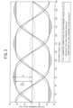
- a case where as illustrated in FIG. 3 , correction in which a third harmonic wave thw1 of a SIN wave type is subtracted from the three-phase voltage command values va0, vb0, and vc0 is performed and corrected three-phase voltage command values va1, vb1, and vc1 are thereby generated, respectively is describe as an example.
- the third harmonic wave thw1 of a SIN wave type for example, a third harmonic wave that has the same waveform as a waveform obtained by synthesizing excesses within the three-phase voltage command values va0, vb0, and vc0 that exceed a value of A 0 ⁇ 3/2, which is ⁇ 3/2 times the amplitude A 0 of the three-phase voltage command values va0, vb0, and vc0, with one another can be employed.
- a third harmonic wave that has the same waveform as a waveform obtained by synthesizing excesses within the three-phase voltage command values va0, vb0, and vc0 that exceed a value of A 0 ⁇ 3/2, which is ⁇ 3/2 times the amplitude A 0 of the three-phase voltage command values va0, vb0, and vc0, with one another can be employed.
- the command value correction unit 43 subtracts excesses exceeding a value of ⁇ 3/2 times the amplitude A 0 of the three-phase voltage command values va0, vb0, and vc0 from the three-phase voltage command values va0, vb0, and vc0, as expressed by the equation (2) below and thereby generates the corrected three-phase voltage command values va1, vb1, and vc1, respectively.
- va 1 va0 ⁇ thw1
- vb1 vb0 ⁇ thw1
- vc1 vc0 ⁇ thw1
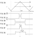
- the PWM control unit 44 generates, based on the corrected three-phase voltage command values va1, vb1, and vc1, gate signals (hereinafter, also referred to as "PWM signals") to drive the high-potential-side switching elements Qah, Qbh, and Qch and the low-potential-side switching elements Qal, Qbl, and Qcl. Specifically, first, the PWM control unit 44, by adding 50% points to the corrected three-phase voltage command values va1, vb1, and vc1, calculates target duty ratios Da, Db, and Dc that have amplitude A 1 of a predetermined magnitude and that vary at most from 0% to 100% with 50% as a vibration center value, as expressed by the equation (3) below.
- the PWM control unit 44 generates PWM signals that, in sections in which the PWM carrier wave P falls below the target duty ratios Da, Db, and Dc, turn on the high-potential-side switching elements Quh, Qvh, and Qwh and turn off the low-potential-side switching elements Qal, Qbl, and Qcl, respectively, as illustrated in FIGS. 5A to 5E .
- the PWM signals are input to the inverter 34.
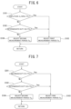
- the second threshold value TH 2 is set to a numerical value large enough to allow a relationship that when it is satisfied that the maximum duty D1 is greater than the first threshold value TH 1 , it is satisfied that the intermediate duty D2 is less than the second threshold value TH 2 to be established, as illustrated in FIG. 8A . That is, as the second threshold value TH 2 , a numerical value at which whenever step S101 in FIG. 6 results in "No", step S102 also results in "No" is employed.
- the measurement timing generation unit 46 determines that the intermediate duty D2 is greater than the second threshold value TH 2 (Yes), the process transitions to step S103. In contrast, when the measurement timing generation unit 46 determines that the intermediate duty D2 is less than or equal to the second threshold value TH 2 (No), the process transitions to step S104.
- the electronic control unit 30 is configured to perform the measurement of the phase currents ia, ib, and ic in the first measurement period Ts 1 when the target duty ratio amplitude value (A 1 +50%), which is a value obtained by adding 50% points to the amplitude A 1 of the target duty ratios Da, Db, and Dc expressed by the equation (4), is less than the first threshold value TH 1 (A 1 +50% ⁇ TH 1 ) or when the target duty ratio amplitude value (A 1 +50%) is greater than or equal to the first threshold value TH 1 (A 1 +50% ⁇ TH 1 ) and the intermediate duty D2 (the second duty ratio), which is the second-largest target duty ratio Da, Db, or Dc among the target duty ratios Da, Db, and Dc, is greater than the second threshold value TH 2 (D2>TH 2 ).
- the electronic control unit 30 according to the first embodiment is capable of making a period in which the first measurement period Ts 1 is selected shorter than the above-described comparative example. Therefore, the period in which the first measurement period Ts 1 is selected becoming short causes a period in which the output torque of the motor 20 is reduced to be short. Because of this configuration, since, compared with the electronic control unit 30 in the above-described comparative example, the electronic control unit 30 according to the first embodiment is configured such that when the measurement period is switched from the second measurement period Ts 2 to the first measurement period Ts 1 , the measurement period is switched to the second measurement period Ts 2 again before the output torque of the motor 20 becomes sufficiently small, as illustrated in FIG. 8C , a variation range of the output torque of the motor 20 becomes small and operation noise and vibration of the electric power steering device 100 can be suppressed.
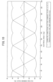
- FIGS. 9A to 9C are simulation results when it is assumed that a start time of the first measurement period Ts 1 from the center C of a PWM signal is 1 ⁇ s, a convergence period of noise is 2 ⁇ s, a start time of the second measurement period Ts 2 from the center C of the PWM signal is 3.75 ⁇ s, the first threshold value TH 1 is 95%, and the second threshold value TH 2 is 84%. From FIGS. 9A to 9C , it is revealed that in the electronic control unit 30 according to the first embodiment, a variation range of the output torque of the motor 20 becomes sufficiently small. In FIGS. 9A to 9C , a case where the amplitude A 1 of the target duty ratios gradually increases is illustrated as an example.
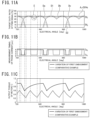
- the phase current measurement unit 35 compares the target duty ratio amplitude value (A 1 +50%) with the first threshold value TH 1 , the first measurement period Ts 1 is not selected in a depressed portion (the depressed portion E in FIG. 11A ) formed by a peak of the waveform being depressed, as illustrated in FIG. 11B . Therefore, in one electrical angle period, the number of switches between the first measurement period Ts 1 and the second measurement period Ts 2 is half the number of switches in the comparative example, the number of variations of the output torque of the motor 20 is half the number of variations in the comparative example, and operation noise and vibration of the electric power steering device 100 can be suppressed.
- va1 va0-MIN(va0, vb0, vc0)
- vb1 vb0-MIN(va0, vb0, vc0)
- vc1 vc0-MIN(va0, vb0, vc0)
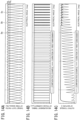
- the command value correction unit 43 performs correction to cut off only excesses exceeding a certain range on the three-phase voltage command values va0, vb0, and vc0 and thereby generates the corrected three-phase voltage command values va1, vb1, and vc1, respectively.
- FIGS. 14A to 14C the command value correction unit 43 performs correction to cut off only excesses exceeding a certain range on the three-phase voltage command values va0, vb0, and vc0 and thereby generates the corrected three-phase voltage command values va1, vb1, and vc1, respectively.
- the PWM control unit 44 adds 50% points to the three-phase voltage command values va0, vb0, and vc0 and thereby calculates the target duty ratios Da, Db, and Dc, respectively, as expressed by the equation (16) below.
- the measurement timing generation unit 46 uses, as the target duty ratio amplitude value (A 1 +50%) to be compared with the first threshold value TH 1 , a value obtained by adding 50% points to the amplitude A 0 of the three-phase voltage command values va0, vb0, and vc0, as expressed by the equation (17) below.
- Da va0 + 50 %
- Db vb0 + 50 %
- Dc vc 0 + 50 %
- a 1 + 50 % A 0 + 50 %
- the command value correction unit 43 subtracts a difference (vm-TH) between the intermediate command value vm and the above-described threshold value TH from the three-phase voltage command values va1, vb1, and vc1 and thereby generates the corrected three-phase voltage command values va1, vb1, and vc1 again, respectively.
- the electric power steering device 100 was described by way of example as an application example of the motor control device according to the present invention, scope of application of the motor control device according to the present invention is not limited to the electric power steering device 100, and the motor control device according to the present invention can be applied to various types of mechanical devices using a motor control device.
- the corrected three-phase voltage command values va1, vb1, and vc1 may be calculated from the q-axis voltage command value vq and the d-axis voltage command value vd in a dimension of voltage (V), and by converting the corrected three-phase voltage command values va1, vb1, and vc1 with a conversion factor calculated from power-supply voltage supplied to the inverter 34 and a dead time amount, the target duty ratios Da, Db, and Dc may be calculated. On this occasion, by likewise converting the amplitude A 0 , the target duty ratio amplitude value is calculated.
Landscapes
- Engineering & Computer Science (AREA)
- Power Engineering (AREA)
- Control Of Ac Motors In General (AREA)
- Control Of Motors That Do Not Use Commutators (AREA)
Applications Claiming Priority (2)
| Application Number | Priority Date | Filing Date | Title |
|---|---|---|---|
| JP2023021717 | 2023-02-15 | ||
| PCT/JP2023/043449 WO2024171563A1 (ja) | 2023-02-15 | 2023-12-05 | モータ制御装置、及び電動パワーステアリング装置 |
Publications (2)
| Publication Number | Publication Date |
|---|---|
| EP4475427A1 true EP4475427A1 (de) | 2024-12-11 |
| EP4475427A4 EP4475427A4 (de) | 2025-04-30 |
Family
ID=92421224
Family Applications (1)
| Application Number | Title | Priority Date | Filing Date |
|---|---|---|---|
| EP23922896.8A Pending EP4475427A4 (de) | 2023-02-15 | 2023-12-05 | Motorsteuerungsvorrichtung und elektrische servolenkvorrichtung |
Country Status (4)
| Country | Link |
|---|---|
| EP (1) | EP4475427A4 (de) |
| JP (1) | JP7588451B1 (de) |
| CN (1) | CN118891821A (de) |
| WO (1) | WO2024171563A1 (de) |
Family Cites Families (4)
| Publication number | Priority date | Publication date | Assignee | Title |
|---|---|---|---|---|
| CN104380594B (zh) * | 2011-12-06 | 2017-07-11 | 三菱电机株式会社 | 功率转换装置 |
| US10432129B2 (en) * | 2015-10-13 | 2019-10-01 | Mitsubishi Electric Corporation | AC rotary machine control device and electric power steering device |
| JP2017093240A (ja) * | 2015-11-16 | 2017-05-25 | オムロンオートモーティブエレクトロニクス株式会社 | 多相電動モータ制御装置 |
| JP6725450B2 (ja) * | 2017-04-12 | 2020-07-15 | 日本電産モビリティ株式会社 | 多相電動モータ制御装置 |
-
2023
- 2023-12-05 EP EP23922896.8A patent/EP4475427A4/de active Pending
- 2023-12-05 WO PCT/JP2023/043449 patent/WO2024171563A1/ja not_active Ceased
- 2023-12-05 JP JP2024530040A patent/JP7588451B1/ja active Active
- 2023-12-05 CN CN202380027990.5A patent/CN118891821A/zh active Pending
Also Published As
| Publication number | Publication date |
|---|---|
| JP7588451B1 (ja) | 2024-11-22 |
| EP4475427A4 (de) | 2025-04-30 |
| CN118891821A (zh) | 2024-11-01 |
| JPWO2024171563A1 (de) | 2024-08-22 |
| WO2024171563A1 (ja) | 2024-08-22 |
Similar Documents
| Publication | Publication Date | Title |
|---|---|---|
| JP5423759B2 (ja) | モータ制御装置及びこれを使用した電動パワーステアリング装置 | |
| US11063544B2 (en) | Inverter device and electric power steering apparatus | |
| US7737648B2 (en) | Motor controller | |
| KR101661057B1 (ko) | Eps 모터 위치 센서의 오프셋 측정장치 및 측정방법 | |
| EP2256018B1 (de) | Elektrische servolenkvorrichtung | |
| JP3674919B2 (ja) | 電動パワーステアリング装置とその制御方法 | |
| JP2015061381A (ja) | 電力変換装置、および、これを用いた電動パワーステアリング装置 | |
| JP4603340B2 (ja) | モータ制御装置、および操舵装置 | |
| CN109562780B (zh) | 电动助力转向装置 | |
| CN109889127B (zh) | 马达控制装置 | |
| JP5136839B2 (ja) | モータ制御装置 | |
| EP3588767B1 (de) | Motorsteuerungsvorrichtung und motorsteuerungsverfahren | |
| EP4475427A1 (de) | Motorsteuerungsvorrichtung und elektrische servolenkvorrichtung | |
| JP5585058B2 (ja) | 回転角検出装置、モータ制御装置、および電動パワーステアリング装置 | |
| CN109889126B (zh) | 马达控制装置 | |
| JP4504893B2 (ja) | 電動パワーステアリング装置 | |
| JP2004312930A (ja) | モータ制御装置 | |
| WO2019220780A1 (ja) | 故障診断方法、電力変換装置、モータモジュールおよび電動パワーステアリング装置 | |
| JP7473125B2 (ja) | 電動モータ用制御装置、ステアリング装置 | |
| JP2010252485A (ja) | モータ制御装置および電動パワーステアリング装置 | |
| EP4607786A1 (de) | Motorsteuerungsvorrichtung und elektrische servolenkvorrichtung | |
| US20260112989A1 (en) | Electric power conversion device, motor control device, and electric power steering device | |
| JP2020092559A (ja) | ステアリング装置 | |
| BR112019020545B1 (pt) | Dispositivo de controle de motor, método de controle de motor e dispositivo de servodireção elétrica | |
| JP2014079112A (ja) | モータ制御装置 |
Legal Events
| Date | Code | Title | Description |
|---|---|---|---|
| STAA | Information on the status of an ep patent application or granted ep patent |
Free format text: STATUS: THE INTERNATIONAL PUBLICATION HAS BEEN MADE |
|
| PUAI | Public reference made under article 153(3) epc to a published international application that has entered the european phase |
Free format text: ORIGINAL CODE: 0009012 |
|
| STAA | Information on the status of an ep patent application or granted ep patent |
Free format text: STATUS: REQUEST FOR EXAMINATION WAS MADE |
|
| 17P | Request for examination filed |
Effective date: 20240904 |
|
| AK | Designated contracting states |
Kind code of ref document: A1 Designated state(s): AL AT BE BG CH CY CZ DE DK EE ES FI FR GB GR HR HU IE IS IT LI LT LU LV MC ME MK MT NL NO PL PT RO RS SE SI SK SM TR |
|
| A4 | Supplementary search report drawn up and despatched |
Effective date: 20250402 |
|
| RIC1 | Information provided on ipc code assigned before grant |
Ipc: H02P 21/22 20160101ALI20250327BHEP Ipc: H02P 23/04 20060101ALI20250327BHEP Ipc: H02P 27/08 20060101AFI20250327BHEP |
|
| GRAP | Despatch of communication of intention to grant a patent |
Free format text: ORIGINAL CODE: EPIDOSNIGR1 |
|
| STAA | Information on the status of an ep patent application or granted ep patent |
Free format text: STATUS: GRANT OF PATENT IS INTENDED |
|
| INTG | Intention to grant announced |
Effective date: 20260130 |
|
| GRAS | Grant fee paid |
Free format text: ORIGINAL CODE: EPIDOSNIGR3 |
|
| GRAA | (expected) grant |
Free format text: ORIGINAL CODE: 0009210 |
|
| STAA | Information on the status of an ep patent application or granted ep patent |
Free format text: STATUS: THE PATENT HAS BEEN GRANTED |