EP4474792A2 - Procédé et dispositif de surveillance de la croissance microbienne, utilisation d'un milieu nutritif emballé - Google Patents
Procédé et dispositif de surveillance de la croissance microbienne, utilisation d'un milieu nutritif emballé Download PDFInfo
- Publication number
- EP4474792A2 EP4474792A2 EP24176144.4A EP24176144A EP4474792A2 EP 4474792 A2 EP4474792 A2 EP 4474792A2 EP 24176144 A EP24176144 A EP 24176144A EP 4474792 A2 EP4474792 A2 EP 4474792A2
- Authority
- EP
- European Patent Office
- Prior art keywords
- nutrient medium
- clean room
- fluid flow
- closure
- controlled environment
- Prior art date
- Legal status (The legal status is an assumption and is not a legal conclusion. Google has not performed a legal analysis and makes no representation as to the accuracy of the status listed.)
- Pending
Links
Images


Classifications
-
- G—PHYSICS
- G01—MEASURING; TESTING
- G01N—INVESTIGATING OR ANALYSING MATERIALS BY DETERMINING THEIR CHEMICAL OR PHYSICAL PROPERTIES
- G01N1/00—Sampling; Preparing specimens for investigation
- G01N1/02—Devices for withdrawing samples
- G01N1/22—Devices for withdrawing samples in the gaseous state
- G01N1/2202—Devices for withdrawing samples in the gaseous state involving separation of sample components during sampling
- G01N1/2208—Devices for withdrawing samples in the gaseous state involving separation of sample components during sampling with impactors
-
- C—CHEMISTRY; METALLURGY
- C12—BIOCHEMISTRY; BEER; SPIRITS; WINE; VINEGAR; MICROBIOLOGY; ENZYMOLOGY; MUTATION OR GENETIC ENGINEERING
- C12M—APPARATUS FOR ENZYMOLOGY OR MICROBIOLOGY; APPARATUS FOR CULTURING MICROORGANISMS FOR PRODUCING BIOMASS, FOR GROWING CELLS OR FOR OBTAINING FERMENTATION OR METABOLIC PRODUCTS, i.e. BIOREACTORS OR FERMENTERS
- C12M37/00—Means for sterilizing, maintaining sterile conditions or avoiding chemical or biological contamination
- C12M37/06—Means for testing the completeness of the sterilization
-
- C—CHEMISTRY; METALLURGY
- C12—BIOCHEMISTRY; BEER; SPIRITS; WINE; VINEGAR; MICROBIOLOGY; ENZYMOLOGY; MUTATION OR GENETIC ENGINEERING
- C12M—APPARATUS FOR ENZYMOLOGY OR MICROBIOLOGY; APPARATUS FOR CULTURING MICROORGANISMS FOR PRODUCING BIOMASS, FOR GROWING CELLS OR FOR OBTAINING FERMENTATION OR METABOLIC PRODUCTS, i.e. BIOREACTORS OR FERMENTERS
- C12M41/00—Means for regulation, monitoring, measurement or control, e.g. flow regulation
-
- G—PHYSICS
- G01—MEASURING; TESTING
- G01N—INVESTIGATING OR ANALYSING MATERIALS BY DETERMINING THEIR CHEMICAL OR PHYSICAL PROPERTIES
- G01N1/00—Sampling; Preparing specimens for investigation
- G01N1/02—Devices for withdrawing samples
- G01N1/22—Devices for withdrawing samples in the gaseous state
- G01N1/2226—Sampling from a closed space, e.g. food package, head space
-
- G—PHYSICS
- G01—MEASURING; TESTING
- G01N—INVESTIGATING OR ANALYSING MATERIALS BY DETERMINING THEIR CHEMICAL OR PHYSICAL PROPERTIES
- G01N1/00—Sampling; Preparing specimens for investigation
- G01N1/02—Devices for withdrawing samples
- G01N1/22—Devices for withdrawing samples in the gaseous state
- G01N1/2273—Atmospheric sampling
-
- G—PHYSICS
- G01—MEASURING; TESTING
- G01N—INVESTIGATING OR ANALYSING MATERIALS BY DETERMINING THEIR CHEMICAL OR PHYSICAL PROPERTIES
- G01N1/00—Sampling; Preparing specimens for investigation
- G01N1/02—Devices for withdrawing samples
- G01N1/22—Devices for withdrawing samples in the gaseous state
- G01N1/2202—Devices for withdrawing samples in the gaseous state involving separation of sample components during sampling
- G01N2001/222—Other features
- G01N2001/2223—Other features aerosol sampling devices
-
- G—PHYSICS
- G01—MEASURING; TESTING
- G01N—INVESTIGATING OR ANALYSING MATERIALS BY DETERMINING THEIR CHEMICAL OR PHYSICAL PROPERTIES
- G01N35/00—Automatic analysis not limited to methods or materials provided for in any single one of groups G01N1/00 - G01N33/00; Handling materials therefor
- G01N35/02—Automatic analysis not limited to methods or materials provided for in any single one of groups G01N1/00 - G01N33/00; Handling materials therefor using a plurality of sample containers moved by a conveyor system past one or more treatment or analysis stations
- G01N35/04—Details of the conveyor system
- G01N2035/0401—Sample carriers, cuvettes or reaction vessels
- G01N2035/0403—Sample carriers with closing or sealing means
- G01N2035/0405—Sample carriers with closing or sealing means manipulating closing or opening means, e.g. stoppers, screw caps, lids or covers
Definitions
- the invention relates to a method for monitoring microbiological contamination in a clean room, preferably an isolator, wherein a fluid flow, in particular an air flow, is discharged from the clean room.
- the invention further relates to a device for monitoring microbiological contamination in a clean room.
- the invention relates to a use, in particular within a clean room and/or within a controlled environment, of a packaged nutrient medium, in particular an impactor, for presenting the nutrient medium in a fluid stream, wherein the fluid stream was taken from a removal location in a clean room, in particular an isolator, in particular wherein the impactor has a nozzle plate behind which the nutrient medium is arranged, wherein the nutrient medium, in particular behind the nozzle plate, is covered by a closure before use.
- the invention is based on the object of monitoring for microbiological contamination within a clean room almost continuously, so that a clean room process does not have to be interrupted or only has to be interrupted for a short time.
- the invention proposes the features of claim 1.
- the invention proposes that the fluid flow Nutrient medium in a controlled environment located outside the clean room, preferably in an environment connected by a fluid line and/or separable from the clean room, wherein the nutrient medium is used to monitor for microbiological contamination.
- the controlled environment can be separated from the clean room except for a supply line, for example the fluid line. It is particularly advantageous that a removal location from which the fluid flow can be discharged from the clean room, preferably the isolator, can be determined relatively freely.
- Another particularly advantageous feature is that it is possible to prevent products in the cleanroom from becoming contaminated, particularly by directly intervening in a cleanroom process taking place in the cleanroom.
- a structurally simple design can be to arrange the controlled environment outside the cleanroom. This can improve accessibility for the exchange.
- a cleanroom process can, for example, be aseptic filling and/or sealing and/or analysis of pharmaceutical products.
- the nutrient medium can be, for example, solid, in particular agar, or liquid, in particular broth.
- the fluid flow can be horizontal and/or vertically or diagonally out of the cleanroom.
- the clean room can be designed, for example, as an isolator.
- Another advantage is that the risk of contamination of products manufactured in the cleanroom during a cleanroom process can also be minimized.
- At least one characteristic variable in particular a volume flow of the fluid flow, is detected and/or that the characteristic variable is regulated, in particular on the basis of the detection.
- an interface delimiting the controlled environment is decontaminated, in particular before the interface is made accessible to the fluid flow to be monitored.
- the interface delimiting the controlled environment can This could, for example, be the nutrient medium that can be coupled and/or exchanged via a docking opening or an access opening.
- a branch or a switch is formed on the fluid line, in particular wherein the fluid flow is controllable.
- a nutrient medium is presented in one of the two devices and is contacted by the fluid flow discharged from the clean room via the fluid line.
- a nutrient medium is placed in the other device and the fluid line or the fluid flow is diverted accordingly. This makes it advantageous to remove one nutrient medium simultaneously with the continuous monitoring of the fluid flow from the clean room for microbiological contamination via the other nutrient medium.
- a decontamination agent in particular a gas or aerosol, preferably hydrogen peroxide, is supplied for decontamination of the interface and/or the controlled environment, in particular wherein the gas or aerosol is supplied from the clean room and/or from a separate decontamination source.
- a particular advantage is that the gas or aerosol used for decontamination can be supplied to different points on the interface and the loop procedures commonly used for fumigation can be used.
- the gas or aerosol flows into the clean room, whereby the decontamination of the interface takes place, for example, via the fluid flow discharged from the clean room.
- the fluid flow is discharged from the clean room at a process point within the clean room, at which a clean room process is preferably carried out, and/or wherein the fluid flow is fed to the nutrient medium in a fluid line which runs at least partially within the clean room. It is particularly advantageous in this case that a continuous measurement, for example of the clean room air, is already possible during the clean room process via a direct line of the fluid flow, whereby the clean room process does not need to be interrupted or only needs to be interrupted for a short time.
- the fluid flow is guided through a particle counter for detecting a particle number and/or particle size, in particular wherein the same fluid flow is subsequently guided to the nutrient medium and/or wherein a partial volume of the fluid flow is branched off, in particular wherein the branched fluid flow is transferred to a particle counter for detecting a particle number and/or wherein the branching takes place outside the clean room.
- the branching of the fluid flow can, for example, be controlled via adjustable and/or controllable nozzles.
- the particle counter is arranged on a fluid line shortly before the controlled environment. It can also be provided, for example, that the particle counter is arranged on a fluid line outside the controlled environment within the clean room.
- a particularly advantageous feature is that monitoring for contamination using functionally different methods can be supplemented with quantitative information, such as the number and/or size of the contamination.
- a particle counter can also be used to more precisely determine the point in time at which contamination occurred.
- the particle counter can be used to determine the number of possible contaminations, while the nutrient medium can be used to detect which type of contamination is present.
- the advantage is that such a combination faster reaction time to interrupt the cleanroom process.
- the nutrient medium is introduced into the controlled environment from the outside and positioned on a holder, in particular wherein the controlled environment is decontaminated after introduction.
- a backflow prevention device in particular a valve, is activated preferably between the controlled environment and the clean room before the nutrient medium is exchanged.
- a controlled room can be formed from the clean room, thus eliminating the need for a controlled room arranged separately from the clean room.
- a particular advantage is that the closure can thus be easily moved to an area outside the flow path of the fluid stream and at the same time removed from the nutrient medium.
- the nutrient medium carrier can, for example, form a housing for the nutrient medium.
- the nutrient medium is removed from the controlled environment after contact with the fluid flow, in particular by a movement of the receptacle.
- the recording is moved horizontally and/or vertically.
- the nutrient medium is closed with the closure after contact with the fluid stream before the nutrient medium is removed from the controlled environment.
- a particular advantage is that this largely prevents contamination of the controlled space.
- the advantage is that the nutrient medium can be easily removed and, for example, fed into an incubator.
- particle detection is carried out in the fluid stream or a further fluid stream and a or the nutrient medium is only and/or automatically presented in the fluid stream when the particle detection has detected a preferably reproducible and/or living object, in particular by diverting the fluid stream, opening a fluid line conducting the fluid stream and/or starting the fluid stream.
- the nutrient medium is only opened, used and/or consumed when the particle counter has demonstrably detected microbiological contamination.
- the features of the independent claim directed to a device are provided according to the invention to solve the problem mentioned.
- the invention proposes to solve the problem mentioned for monitoring microbiological contamination in a clean room that an enclosure which encloses a controlled environment, for example the one already mentioned, comprises a receptacle, for example the one already mentioned, for presenting a nutrient medium, for example the one already mentioned, in the controlled environment, a fluidic connection for connection to the clean room and an interface which delimits the controlled environment, in particular for providing the nutrient medium.
- the fluidic connection has a branch or a switch which is designed to divert a fluid flow.
- a fluid stream which is discharged in particular from the clean room, can be continuously monitored for microbiological contamination, for example by using two separate controlled environments in which a nutrient medium can be presented.
- a decontamination device is formed, by means of which at least the interface, in particular the controlled environment, can be decontaminated.
- the decontamination device is designed to supply a decontamination agent, in particular gas or aerosol, for example hydrogen peroxide, for example from the clean room and/or from a separate decontamination source to the interface in order to decontaminate the interface.
- a decontamination agent in particular gas or aerosol, for example hydrogen peroxide, for example from the clean room and/or from a separate decontamination source to the interface in order to decontaminate the interface.
- the interface is designed as part of the housing, in particular as part of a locking device of the housing.
- the interface is formed by a closure of the nutrient medium.
- the advantage here is that it is possible to close the culture medium before removal.
- the controlled environment has a supply line and/or a discharge line for a decontamination agent of the decontamination device and/or wherein the decontamination device is designed as part of the device.
- the decontamination agent is supplied to the controlled environment via a fluid stream which is discharged from the clean room.
- the receptacle is formed in the controlled environment, in particular wherein the receptacle is designed to open the device to the outside.
- the holder can, for example, be movable horizontally and/or vertically.
- a change of the nutrient medium can be carried out independently of a cleanroom process taking place in the cleanroom.
- the device has a lifting device.
- the holder is vertically movable.
- a simple possibility for removing the nutrient medium is thus realized.
- a device comprising the or a receptacle for presenting a or the nutrient medium, a fluidic connection, in particular from a removal location in the clean room, which can be coupled to the nutrient medium and a means for preferably remotely removing a closure of the nutrient medium before the fluidic connection is coupled.
- the advantage here is that the nutrient medium, which can be provided with a closure cap, can be replaced without disturbing the interior of the clean room.
- Removal can preferably be automated or manual. This can be done, for example, fully automatically or manually via remote control.
- a coupling can be, for example, a mechanical connection between the nutrient medium and the fluidic connection or, for example, the opening of a barrier be.
- a particularly advantageous feature is that it can prevent a contaminated fluid stream from flowing into the clean room.
- Another advantage is that the controlled environment can be created by the cleanroom itself.
- an elastic membrane is formed outside a flow path of the fluid flow between the isolator and the controlled environment.
- the flow path is, for example, the flow area through which a fluid passes during fluid flow.
- the membrane is fluidically connected to the flow area while a fluid flow is being discharged from the clean room into the controlled environment. Another advantage is that the membrane's elasticity also allows the fluidic connection to be released as soon as no more fluid flow is being discharged.
- the membrane is designed as a partial section of or an enclosure of or a controlled environment or the clean room.
- a movable closure of the controlled environment or the clean room, in particular the isolator can be achieved, in particular for changing the nutrient medium.
- the device has a transfer device, in particular a pivoting device, which is designed with a closure receptacle.
- the closure of the nutrient medium can be removed.
- a particular advantage is that the closure can thus be placed outside the flow path of the fluid stream.
- closure receptacle encompasses the closure of the nutrient medium.
- the device comprises the or a fluid line, wherein in particular the interface is formed as part of the fluid line, and/or wherein a flow path of the fluid flow through the fluid line between an opening of the fluid line facing away from the device and the receptacle is less than one meter, preferably less than two or three meters, in particular less than four meters.
- the fluid line can be closed, in particular when the transfer device is arranged in a remote position.
- a particularly advantageous feature is that contamination cannot spread from the controlled volume into the clean room.
- the particle counter or a particle counter is arranged in the flow path upstream of the nutrient medium and/or that the fluid flow is branched off.
- a flow divider is formed.
- the particle counter is designed just before the controlled environment. It can also be provided, for example, that the particle counter is designed inside the clean room.
- a particularly advantageous feature is that a method for monitoring microbiological contamination can be supplemented by quantitative analyses.
- the particle counter can provide information about how many contaminants are present, while the nutrient medium can detect which type of contaminants have been detected.
- a valve can be used which has as little contamination surface as possible or as few surfaces that are difficult to decontaminate as possible.
- the device has a pump, in particular for introducing the fluid flow into the controlled environment.
- the direction of the fluid flow can be influenced. This makes it possible, for example, to discharge the fluid flow horizontally and/or vertically out of the clean room.
- the device has at least one sensor for detecting the or a characteristic variable of the fluid flow, and/or wherein the device has a control device for regulating the fluid flow.
- the invention provides the features of the independent claim directed to the use of a packaged nutrient medium.
- a packaged nutrient medium in particular an impactor, for presenting the nutrient medium in a fluid stream, wherein the fluid stream was taken from a removal location in a clean room, in particular an isolator, in particular wherein the impactor has a nozzle plate behind which the nutrient medium is arranged, wherein the nutrient medium, in particular behind the nozzle plate, is covered by a closure, in particular a lid, before use
- the closure is gripped with a closure receptacle and removed from the nutrient medium, in particular the nozzle plate, and that a fluidic connection is established from the removal location to the nutrient medium, in particular the nozzle plate.
- the use can take place within a clean room, in particular an impactor, and/or within a controlled environment.
- the nutrient medium in particular the nozzle plate
- the closure is closed after use in the opposite direction by the closure, which is gripped, for example, by the closure receptacle.
- the impactor is preferably designed to accelerate the fluid flow, in particular via the nozzle plate.
- the nozzle plate is preferably designed with slots arranged in the circumferential direction, which have such a small opening dimension that contaminants can only penetrate through a negative pressure. Particularly advantageous is that it is thus possible to contact the fluid flow discharged from the clean room with the nutrient medium, which in turn enables monitoring for microbiological contamination.
- the clean room and/or the controlled environment has an opening that can be closed with the closure receptacle, which covers an outer side of the closure.
- the nutrient medium can be closed for removal with a closure located in the clean room or controlled environment. This prevents contamination from entering the nutrient medium after removal.
- a closure holder with which an opening can be closed makes it possible to close and remove the nutrient medium closed with the closure through the opening without disturbing the clean room or controlled environment.
- Another advantage is that it can be ensured that only the fluid flow that is discharged from the clean room contacts the nutrient medium. This advantageously prevents a fluid flow that is not discharged from the clean room from contacting the nutrient medium and leading to a falsified measurement result.
- the impactor is removed from the fluid flow after exposing the nutrient medium and is subjected to incubation, in particular wherein the nutrient medium is closed before removal.
- a particularly advantageous feature is that microbiological Contamination can be detected. Another advantage is that if contamination occurs, sealing the culture medium before removal can prevent further areas from being contaminated.
- the closure receptacle forms a closure of a controlled environment before contacting the closure, in particular on a side facing away from the closure.
- closure holder forms an additional boundary to the clean room and the likelihood of contamination of the clean room can be reduced. Another advantage is that contamination of the closure does not necessarily result in contamination of the controlled room.
- the fluidic connection comprises a line section.
- a particularly advantageous feature is that the fluid flow can be diverted from the clean room into the controlled environment.
- the fluidic connection is established by means of a coupling which carries out a relative movement between the nozzle plate and a line section.
- the coupling can, for example, be the fluidic connection between a bottom side of the line section and a top side of the nozzle plate.
- a particularly advantageous feature is that a detachable connection between the nozzle plate and the pipe section is possible, so that the line sections can be exchanged and/or changed advantageously.
- Another particularly advantageous feature is that it can be ensured that only the fluid flow that is discharged from the clean room contacts the nutrient medium via the coupling.
- a device for monitoring microbiological contamination designated as a whole by 1, has a closure holder 2 for a closure 3, which can be placed on a nutrient medium carrier 11, wherein the nutrient medium carrier 11 presents a nutrient medium 4, and an impactor 29, which is partially enclosed by a housing 13.
- the housing 13 has an opening 24 that can be closed with the closure holder 2, which covers an outside of the closure 3.
- the nutrient medium 4 is arranged behind a nozzle plate 25.
- the impactor 29 is connected to a pump 35 (not shown) via a suction connection 30.
- the pump thus sucks fluid from a fluid line 7 through the Nozzle plate 25 past the nutrient medium 4. Contaminants carried along are deposited on the nutrient medium 4 and can then be detected.
- the fluid line 7 can run at a process point within a clean room 20, where a clean room process is preferably carried out, and/or partially within the clean room 20.
- the clean room 20 is arranged above the fluid line 7.
- a fluid flow 17 from the clean room 20 can be discharged from a removal location 28, for example via the aforementioned pump 35, vertically via the fluid line 7 and a flow channel that defines a flow path of the fluid flow 17, and fed to a controlled environment 5.
- the fluid flow 17 is accelerated by the nozzle plate 25, which is designed with slots arranged in the circumferential direction with a clear opening dimension.
- a controlled environment 5 is delimited by an interface 6 which is first decontaminated by a gas or aerosol, in particular by a gas containing hydrogen peroxide, before the interface 6 is made accessible to the fluid stream 17 to be sampled or monitored and after a nutrient medium carrier 11, which does not contain a nutrient medium 4 for the decontamination, has been connected to the controlled environment 5.
- the gas or aerosol is supplied from the clean room 20 and/or from a separate decontamination source, in particular a decontamination device. After the Decontamination, the nutrient medium carrier 11 is exchanged for a nutrient medium carrier 11 with nutrient medium 4.
- the nutrient medium 4 is thus located in the controlled environment 5 and is presented by a holder 8 on a nutrient medium carrier 11.
- closure 3 of the sewing medium 4 is first removed via a transfer movement of the closure holder 2, which comprises an outer side of the closure 3.
- the fluid line 7 is only fluidically connected to the nutrient medium 4 after the closure 3 of the nutrient medium 4 has been removed.
- the fluid stream 17 can subsequently contact the nutrient medium 4 outside the clean room 20 in the decontaminated controlled environment 5.
- this embodiment provides that a receptacle 8 of the device 1 can be opened outwards via a transfer movement.
- a valve not shown in this figure is activated, whereby a backflow of the fluid stream 17 can be prevented.
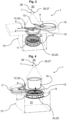
- Fig. 2 shows in contrast to Fig. 1 a further device 1 for monitoring microbiological contamination from the clean room 20.
- the closure receptacle 2 which is designed to receive the closure 3 of the nutrient medium 4, is attached to the nutrient medium 4 via a lifting device 32 or pivoting device 12, which enables the closure receptacle 2 to carry out a lifting movement 10 and/or a pivoting movement 9, whereby the closure 3 of the nutrient medium carrier 11 is removed or placed on the nutrient medium carrier 11.
- a fluid guide screen 18 which is designed to carry out a horizontal pivoting movement 9.
- the fluid line 7 can thus be closed by pivoting the fluid guide screen 18 from the side to a position above the nutrient medium carrier 11 after the closure receptacle 2 with the closure 3 has been pivoted to the side.
- closure 3 it is shown that, in contrast to the previous embodiment, it is possible for the closure 3 to be positioned in the controlled environment 5 outside the flow path of the fluid stream 17.
- Fig. 3 shows a three-dimensional representation of an alternative embodiment of a device 1 according to Fig. 2 .
- a removal chamber 31 is formed, which is formed by the housing 13.
- Fig. 4 and Fig. 5 show a further embodiment according to the previous embodiments, with the difference that the housing 13 does not provide two, but only one placeholder for the closure receptacle 2, which surrounds the closure 3.
- the fluid guide plate 18 is not pivotable in this embodiment, but vertically movable in order to effect the connection of the fluid flow 17.
- Fig. 5 shows the fluid guide orifice 18 in the docked state.
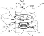
- Fig. 6 In contrast to the previous embodiments, it shows an elastic membrane 14 which is formed outside a flow path of the fluid flow 17 between a removal chamber 31 and the controlled environment 5 and forms a partial section of the housing 13.
- the impactor 29 can be removed and supplied via the removal chamber 31.
- the membrane 4 can be connected or is connected to the nutrient medium 4, in particular to the nutrient medium carrier 11, and is moved vertically in order to remove the closure 3 and/or to couple the fluid line 7 from the lifting device 32, which realizes a lifting movement 10 of the receptacle 8.
- Fig. 7 It is shown that the nutrient medium 4, which is positioned in the nutrient medium carrier 11, is not fluidically connected to the membrane 14. In this position, the nutrient medium 4 can be introduced into the controllable environment 5.
- the nutrient medium with the closure 3, in particular the nutrient medium carrier 11, is lifted to the closure holder 2 via the lifting device 32 become.
- a fluidic connection 27, which comprises a line piece 26, is established by means of a coupling 15, which carries out a relative movement between the nozzle plate 25 and the line piece 26.
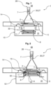
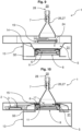
- Fig. 9 shows that the nutrient medium carrier 11 is subsequently lowered again, whereby the elastic membrane 14 is also lowered via the connection of the nutrient medium carrier 11 with the elastic membrane 14.
- the closure receptacle 2 which comprises the closure 3 of the nutrient medium 4
- the closure receptacle 3 is placed outside the flow path of the fluid stream 17 within the controlled environment 5 via a pivoting movement 9 and the nutrient medium 4 is presented without the closure 3.
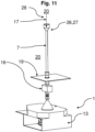
- Fig. 11 and 12 show the entire device 1, with the fluid line 7 running partially within the clean room 20.
- a particle counter 16 is shown, which in Fig. 11 in front of a floor plate 19 of the clean room 20, for example an isolator, and in Fig. 12 is positioned on the fluid line 7 within the clean room 20.
- the fluid flow 17 discharged from the clean room 20 via the fluid line 7 can be passed through the particle counter 16 before coming into contact with the nutrient medium 4.
- a side wall and/or a ceiling can also be used to guide the fluid line 7.
- a further variant not shown in this embodiment also consists in branching off the fluid flow 17, for example, outside the clean room 20, wherein the branched fluid flow 17 is also guided through the particle counter 16. becomes.
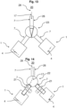
- Fig. 13 and Fig. 14 show a basic structure for monitoring microbiological contamination in a clean room 20, wherein, in contrast to the previous embodiments, two separate devices 1 are used, each of which is formed with a fluid line 7.
- the fluid flow 17, which is discharged from the clean room 20 for monitoring for microbiological contamination, can thus be directed into two different devices 1 either via an adjustable switch 23 or via a branch 22 of the fluid line 7.
- One of the two devices 1 presents a nutrient medium 4, which is contacted by the fluid flow 17 that is discharged from the clean room 20.
- the fluid flow 17 can be diverted, for example via the switch 23 or via the branch 22 of the fluid line 7, which is preferably designed with a valve 21, into the other device 1, into which a new nutrient medium 4 is inserted, preferably before the fluid flow 17 is diverted.
- the branch 22 of the fluid line 7, which is connected to the device 1 in which the nutrient medium 4 is to be changed, is blocked, for example, via the valve 21, which is in particular in a blocking position.
- the valve 21 is located as close as possible to the branch 22 in order to avoid dead spaces. It can therefore be said that continuous monitoring for microbiological contamination is possible.
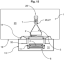
- Fig. 15 shows the modified device 1 according to Fig. 6 in an installed state in a clean room 20. It turns out that the controlled environment 5 is formed by the clean room 20 and that the membrane 14 is designed as a partial section of the clean room 20. In addition, it can be seen that the controlled environment 5, except for the fluid line 7, can be separated from the clean room 20.
- Fig. 16 shows a further device 1 according to the invention with an interface 6 which laterally delimits the controlled environment 5 and can be folded down via a pivoting movement 9, which is decontaminated at least on the inside before the interface 6 is made accessible for the fluid flow 17 to be monitored.
- a backflow prevention device is attached to the fluid line 7, which in this embodiment is designed as a ball valve 33 between the controlled environment 5 and the clean room 20.
- another backflow prevention device for example a diaphragm valve or another shut-off device known to the person skilled in the art, is attached instead of the ball valve 33.
- the decontamination agent required for decontamination is supplied to the interface 6 and the controlled environment 5 via a nozzle 34.
- closure 3 is removed from the nutrient medium carrier 11, which presents the nutrient medium 4, via a pivoting movement 9 of the closure receptacle 2, or is placed on the nutrient medium carrier 11 to close the nutrient medium 4.
- Figure 17 shows another device for monitoring microbiological contamination 1. It shows a Fluid line 7 or fluidic connection 27 with a particle counter 16, which takes fluid samples, here gas samples, at a sampling point 36 within the controlled environment 5, which in this embodiment is formed by the clean room 20 itself. In this case, a controlled fluid flow 17 is sucked in via a pump 35 arranged outside the clean room 20 (on the left in the picture) and thus fed to the particle counter 16.
- a pump 35 arranged outside the clean room 20 (on the left in the picture) and thus fed to the particle counter 16.
- the nutrient medium carrier 11 with the nutrient medium 4 presented therein is also located within the controlled environment 5 or clean room 20 parallel to the particle counter 16.
- the nutrient medium carrier 11 is connected to another pump 35 arranged outside the clean room 20 via another fluid line 7 or fluidic connection 27, via which the fluid flow 17 is sucked in, which in turn enables a defined contact of the fluid flow 17 of the clean room 20 with the nutrient medium 4.
- continuous monitoring for microbiological contamination is initially carried out via the particle counter 16, with the nutrient medium 4 initially closed by the closure 3 and thus not presented.
- no fluid flow 17 is initially sucked in by the pump 35 (in the right-hand image), which is connected to the nutrient medium carrier 11 via the fluid line 7.
- the closure 3 of the nutrient medium 4 is automatically removed from the closure holder 2 via a pivoting movement 9 and the nutrient medium 4 is presented.
- the fluid flow 17 is thus sucked in via the (right) pump 35, which is connected to the nutrient medium carrier 11 via the fluid line 7, which in turn contacts the presented nutrient medium 4.
- the nutrient medium 4 only in the fluid stream 17 is presented when contamination has been detected by the particle counter 16.
- the nutrient medium 4 can be examined after the presentation in a manner known per se to determine whether the contamination is capable of multiplying.
- the nutrient medium 4 is located outside the clean room 20 within a controlled environment 5.
- the fluid line 7 or fluidic connection 27 connects, according to Fig. 16 , the clean room 20 with a controlled environment 5, for example as in the previous embodiments, and is additionally designed with a switchable valve 21. As soon as the particle counter 16 has detected microbiological contamination, the valve 21 is switched to an open position, whereby the nutrient medium 4 is again automatically presented and contacted by the fluid flow 17.
- the nutrient medium 4 and the particle counter 16 are connected to a common pump 35.
- the nutrient medium 4 can thus be arranged in a switchable bypass to the fluid flow of the particle counter 16.
- the nutrient medium 4 can also be provided with an upstream, in particular decoupleable, fluid line 7 (cf. e.g. Fig. 12 ).
- a fluid stream 17 is discharged via a fluid line 7 from a clean room 20 into a controlled environment 5, wherein a nutrient medium 4 is presented in the controlled environment 5 and with which the fluid stream 17 is contacted and is then removed from the controlled environment 5 in such a way that a Cleanroom process does not have to be interrupted.
Landscapes
- Health & Medical Sciences (AREA)
- Life Sciences & Earth Sciences (AREA)
- Chemical & Material Sciences (AREA)
- Engineering & Computer Science (AREA)
- Wood Science & Technology (AREA)
- Organic Chemistry (AREA)
- Bioinformatics & Cheminformatics (AREA)
- Zoology (AREA)
- Biochemistry (AREA)
- General Health & Medical Sciences (AREA)
- Biomedical Technology (AREA)
- Molecular Biology (AREA)
- Analytical Chemistry (AREA)
- General Engineering & Computer Science (AREA)
- Sustainable Development (AREA)
- Genetics & Genomics (AREA)
- Biotechnology (AREA)
- Microbiology (AREA)
- Physics & Mathematics (AREA)
- General Physics & Mathematics (AREA)
- Immunology (AREA)
- Pathology (AREA)
- Epidemiology (AREA)
- Public Health (AREA)
- Apparatus Associated With Microorganisms And Enzymes (AREA)
Applications Claiming Priority (1)
| Application Number | Priority Date | Filing Date | Title |
|---|---|---|---|
| DE102023113119.2A DE102023113119A1 (de) | 2023-05-17 | 2023-05-17 | Verfahren und Vorrichtung zur Überwachung mikrobiellen Wachstums, Verwendung eines verpackten Nährmediums |
Publications (2)
| Publication Number | Publication Date |
|---|---|
| EP4474792A2 true EP4474792A2 (fr) | 2024-12-11 |
| EP4474792A3 EP4474792A3 (fr) | 2025-03-12 |
Family
ID=91129550
Family Applications (1)
| Application Number | Title | Priority Date | Filing Date |
|---|---|---|---|
| EP24176144.4A Pending EP4474792A3 (fr) | 2023-05-17 | 2024-05-15 | Procédé et dispositif de surveillance de la croissance microbienne, utilisation d'un milieu nutritif emballé |
Country Status (3)
| Country | Link |
|---|---|
| US (1) | US20240384217A1 (fr) |
| EP (1) | EP4474792A3 (fr) |
| DE (1) | DE102023113119A1 (fr) |
Family Cites Families (9)
| Publication number | Priority date | Publication date | Assignee | Title |
|---|---|---|---|---|
| US6615679B1 (en) * | 2000-08-15 | 2003-09-09 | Particle Measuring Systems, Inc. | Ensemble manifold, system and method for monitoring particles in clean environments |
| WO2003081212A2 (fr) * | 2002-03-16 | 2003-10-02 | Pathogenus, Inc. | Echantillonneur d'air reglable avec mesures psychometriques d'aerosols viables et non viables |
| US20040185521A1 (en) * | 2003-03-20 | 2004-09-23 | Shigeru Yoshida | Microorganism sampling method and microorganism sampling device |
| JP4771184B2 (ja) * | 2010-01-19 | 2011-09-14 | 株式会社日立プラントテクノロジー | 浮遊菌捕集装置、浮遊菌計測方法及び浮遊菌計測システム |
| ITRM20130128U1 (it) * | 2013-07-23 | 2015-01-24 | Particle Measuring Systems S R L | Dispositivo per il campionamento microbico dell'aria |
| KR102880992B1 (ko) * | 2018-11-16 | 2025-11-03 | 파티클 머슈어링 시스템즈, 인크. | 로봇 제어된 제조 장벽 시스템을 위한 입자 샘플링 시스템 및 방법 |
| DE102019207280A1 (de) * | 2019-05-18 | 2020-11-19 | Syntegon Technology Gmbh | Anlage zum Handhaben von empfindlichen Produkten, insbesondere Verpackungsanlage |
| JP7591031B2 (ja) * | 2019-08-26 | 2024-11-27 | パーティクル・メージャーリング・システムズ・インコーポレーテッド | トリガされるサンプリングシステム及び方法 |
| WO2022084369A1 (fr) * | 2020-10-23 | 2022-04-28 | Merck Patent Gmbh | Cartouche pour plaques de culture, procédé d'échantillonnage d'air et système d'isolateur de production |
-
2023
- 2023-05-17 DE DE102023113119.2A patent/DE102023113119A1/de active Pending
-
2024
- 2024-05-07 US US18/656,978 patent/US20240384217A1/en active Pending
- 2024-05-15 EP EP24176144.4A patent/EP4474792A3/fr active Pending
Also Published As
| Publication number | Publication date |
|---|---|
| US20240384217A1 (en) | 2024-11-21 |
| EP4474792A3 (fr) | 2025-03-12 |
| DE102023113119A1 (de) | 2024-11-21 |
Similar Documents
| Publication | Publication Date | Title |
|---|---|---|
| DE2716317C2 (fr) | ||
| DE68928157T2 (de) | Verfahren und Vorrichtung zur Bestimmung von in einer Flüssigkeitsprobe enthaltenen Teilchen | |
| EP0179296B1 (fr) | Dispositif de détermination de la composition quantitative de gaz | |
| DE102010001391A1 (de) | Sondeneinrichtung zum Messen einer Messgröße eines in einem Prozessbehälter enthaltenen Messmediums, insbesondere für sterile Anwendungen | |
| DE102007043382A1 (de) | Schnüffellecksucher | |
| EP1941267A2 (fr) | Armature destinee a recevoir une sonde | |
| DE69103156T2 (de) | Verfahren und probenentnahmevorrichtung zur entnahme von repräsentativen flüssigkeitsproben aus einem unter druck stehenden flüssigkeitssystem. | |
| DE2440805A1 (de) | Verfahren und vorrichtung zum analysieren einer reihe von fluidproben | |
| DE3249399C2 (de) | Einrichtung zur sterilen Probeentnahme aus einem Fermenter | |
| DE112014001109T5 (de) | Mit einem Strahl geladener Teilchen arbeitende Vorrichtung und Filterelement | |
| EP1119752A1 (fr) | Detecteur de fuites pelliculaire | |
| EP3688459B1 (fr) | Dispositif de détection de la qualité d'un liquide dans un tube d'alimentation | |
| EP4474792A2 (fr) | Procédé et dispositif de surveillance de la croissance microbienne, utilisation d'un milieu nutritif emballé | |
| AT3054U1 (de) | Radeinheit für ein kraftfahrzeug mit reifenfüllanlage | |
| EP4108264A1 (fr) | Dispositif de stérilisation doté d'un dispositif de commande | |
| DE102004005672A1 (de) | Kultivierungsvorrichtung | |
| WO1992006363A1 (fr) | Procede et dispositif pour l'extraction et la manutention d'echantillons | |
| DE102008004426A1 (de) | Messvorrichtung und Messverfahren zur automatisierten Messung der Eigenschaften des in einer Biogasanlage befindlichen Faulschlamms | |
| EP0408939B1 (fr) | Procédé et dispositif pour l'échantillonnage de l'air du confinement pour un réacteur | |
| DE102012209961A1 (de) | Verschließbare Einheit für einen Isolator oder Reinraum | |
| DE20215855U1 (de) | Mehrfachsammler für Gase, Aerosole und Flüssigkeiten mit Auffangvorrichtungen | |
| DE4335514C2 (de) | Vorrichtung zum Austauschen von Fluids | |
| DE19950341C1 (de) | Vorrichtung zum Abscheiden von Mikroorganismen aus Mikroorganismen-enthaltenden Gasen und ihre Verwendung | |
| AT406650B (de) | Vorrichtung zum isolieren eines in einem isolierraum vorhandenen testgases gegen einen bedienungsraum | |
| DE4209200A1 (de) | Vorrichtung zur untersuchung von gasen |
Legal Events
| Date | Code | Title | Description |
|---|---|---|---|
| PUAI | Public reference made under article 153(3) epc to a published international application that has entered the european phase |
Free format text: ORIGINAL CODE: 0009012 |
|
| STAA | Information on the status of an ep patent application or granted ep patent |
Free format text: STATUS: THE APPLICATION HAS BEEN PUBLISHED |
|
| AK | Designated contracting states |
Kind code of ref document: A2 Designated state(s): AL AT BE BG CH CY CZ DE DK EE ES FI FR GB GR HR HU IE IS IT LI LT LU LV MC ME MK MT NL NO PL PT RO RS SE SI SK SM TR |
|
| PUAL | Search report despatched |
Free format text: ORIGINAL CODE: 0009013 |
|
| AK | Designated contracting states |
Kind code of ref document: A3 Designated state(s): AL AT BE BG CH CY CZ DE DK EE ES FI FR GB GR HR HU IE IS IT LI LT LU LV MC ME MK MT NL NO PL PT RO RS SE SI SK SM TR |
|
| RIC1 | Information provided on ipc code assigned before grant |
Ipc: C12M 1/22 20060101ALI20250204BHEP Ipc: G01N 1/22 20060101AFI20250204BHEP |
|
| STAA | Information on the status of an ep patent application or granted ep patent |
Free format text: STATUS: REQUEST FOR EXAMINATION WAS MADE |
|
| 17P | Request for examination filed |
Effective date: 20250912 |