EP4474792A2 - Method and apparatus for monitoring microbial growth, use of a packaged nutrient medium - Google Patents
Method and apparatus for monitoring microbial growth, use of a packaged nutrient medium Download PDFInfo
- Publication number
- EP4474792A2 EP4474792A2 EP24176144.4A EP24176144A EP4474792A2 EP 4474792 A2 EP4474792 A2 EP 4474792A2 EP 24176144 A EP24176144 A EP 24176144A EP 4474792 A2 EP4474792 A2 EP 4474792A2
- Authority
- EP
- European Patent Office
- Prior art keywords
- nutrient medium
- clean room
- fluid flow
- closure
- controlled environment
- Prior art date
- Legal status (The legal status is an assumption and is not a legal conclusion. Google has not performed a legal analysis and makes no representation as to the accuracy of the status listed.)
- Pending
Links
Images


Classifications
-
- G—PHYSICS
- G01—MEASURING; TESTING
- G01N—INVESTIGATING OR ANALYSING MATERIALS BY DETERMINING THEIR CHEMICAL OR PHYSICAL PROPERTIES
- G01N1/00—Sampling; Preparing specimens for investigation
- G01N1/02—Devices for withdrawing samples
- G01N1/22—Devices for withdrawing samples in the gaseous state
- G01N1/2202—Devices for withdrawing samples in the gaseous state involving separation of sample components during sampling
- G01N1/2208—Devices for withdrawing samples in the gaseous state involving separation of sample components during sampling with impactors
-
- C—CHEMISTRY; METALLURGY
- C12—BIOCHEMISTRY; BEER; SPIRITS; WINE; VINEGAR; MICROBIOLOGY; ENZYMOLOGY; MUTATION OR GENETIC ENGINEERING
- C12M—APPARATUS FOR ENZYMOLOGY OR MICROBIOLOGY; APPARATUS FOR CULTURING MICROORGANISMS FOR PRODUCING BIOMASS, FOR GROWING CELLS OR FOR OBTAINING FERMENTATION OR METABOLIC PRODUCTS, i.e. BIOREACTORS OR FERMENTERS
- C12M37/00—Means for sterilizing, maintaining sterile conditions or avoiding chemical or biological contamination
- C12M37/06—Means for testing the completeness of the sterilization
-
- C—CHEMISTRY; METALLURGY
- C12—BIOCHEMISTRY; BEER; SPIRITS; WINE; VINEGAR; MICROBIOLOGY; ENZYMOLOGY; MUTATION OR GENETIC ENGINEERING
- C12M—APPARATUS FOR ENZYMOLOGY OR MICROBIOLOGY; APPARATUS FOR CULTURING MICROORGANISMS FOR PRODUCING BIOMASS, FOR GROWING CELLS OR FOR OBTAINING FERMENTATION OR METABOLIC PRODUCTS, i.e. BIOREACTORS OR FERMENTERS
- C12M41/00—Means for regulation, monitoring, measurement or control, e.g. flow regulation
-
- G—PHYSICS
- G01—MEASURING; TESTING
- G01N—INVESTIGATING OR ANALYSING MATERIALS BY DETERMINING THEIR CHEMICAL OR PHYSICAL PROPERTIES
- G01N1/00—Sampling; Preparing specimens for investigation
- G01N1/02—Devices for withdrawing samples
- G01N1/22—Devices for withdrawing samples in the gaseous state
- G01N1/2226—Sampling from a closed space, e.g. food package, head space
-
- G—PHYSICS
- G01—MEASURING; TESTING
- G01N—INVESTIGATING OR ANALYSING MATERIALS BY DETERMINING THEIR CHEMICAL OR PHYSICAL PROPERTIES
- G01N1/00—Sampling; Preparing specimens for investigation
- G01N1/02—Devices for withdrawing samples
- G01N1/22—Devices for withdrawing samples in the gaseous state
- G01N1/2273—Atmospheric sampling
-
- G—PHYSICS
- G01—MEASURING; TESTING
- G01N—INVESTIGATING OR ANALYSING MATERIALS BY DETERMINING THEIR CHEMICAL OR PHYSICAL PROPERTIES
- G01N1/00—Sampling; Preparing specimens for investigation
- G01N1/02—Devices for withdrawing samples
- G01N1/22—Devices for withdrawing samples in the gaseous state
- G01N1/2202—Devices for withdrawing samples in the gaseous state involving separation of sample components during sampling
- G01N2001/222—Other features
- G01N2001/2223—Other features aerosol sampling devices
-
- G—PHYSICS
- G01—MEASURING; TESTING
- G01N—INVESTIGATING OR ANALYSING MATERIALS BY DETERMINING THEIR CHEMICAL OR PHYSICAL PROPERTIES
- G01N35/00—Automatic analysis not limited to methods or materials provided for in any single one of groups G01N1/00 - G01N33/00; Handling materials therefor
- G01N35/02—Automatic analysis not limited to methods or materials provided for in any single one of groups G01N1/00 - G01N33/00; Handling materials therefor using a plurality of sample containers moved by a conveyor system past one or more treatment or analysis stations
- G01N35/04—Details of the conveyor system
- G01N2035/0401—Sample carriers, cuvettes or reaction vessels
- G01N2035/0403—Sample carriers with closing or sealing means
- G01N2035/0405—Sample carriers with closing or sealing means manipulating closing or opening means, e.g. stoppers, screw caps, lids or covers
Definitions
- the invention relates to a method for monitoring microbiological contamination in a clean room, preferably an isolator, wherein a fluid flow, in particular an air flow, is discharged from the clean room.
- the invention further relates to a device for monitoring microbiological contamination in a clean room.
- the invention relates to a use, in particular within a clean room and/or within a controlled environment, of a packaged nutrient medium, in particular an impactor, for presenting the nutrient medium in a fluid stream, wherein the fluid stream was taken from a removal location in a clean room, in particular an isolator, in particular wherein the impactor has a nozzle plate behind which the nutrient medium is arranged, wherein the nutrient medium, in particular behind the nozzle plate, is covered by a closure before use.
- the invention is based on the object of monitoring for microbiological contamination within a clean room almost continuously, so that a clean room process does not have to be interrupted or only has to be interrupted for a short time.
- the invention proposes the features of claim 1.
- the invention proposes that the fluid flow Nutrient medium in a controlled environment located outside the clean room, preferably in an environment connected by a fluid line and/or separable from the clean room, wherein the nutrient medium is used to monitor for microbiological contamination.
- the controlled environment can be separated from the clean room except for a supply line, for example the fluid line. It is particularly advantageous that a removal location from which the fluid flow can be discharged from the clean room, preferably the isolator, can be determined relatively freely.
- Another particularly advantageous feature is that it is possible to prevent products in the cleanroom from becoming contaminated, particularly by directly intervening in a cleanroom process taking place in the cleanroom.
- a structurally simple design can be to arrange the controlled environment outside the cleanroom. This can improve accessibility for the exchange.
- a cleanroom process can, for example, be aseptic filling and/or sealing and/or analysis of pharmaceutical products.
- the nutrient medium can be, for example, solid, in particular agar, or liquid, in particular broth.
- the fluid flow can be horizontal and/or vertically or diagonally out of the cleanroom.
- the clean room can be designed, for example, as an isolator.
- Another advantage is that the risk of contamination of products manufactured in the cleanroom during a cleanroom process can also be minimized.
- At least one characteristic variable in particular a volume flow of the fluid flow, is detected and/or that the characteristic variable is regulated, in particular on the basis of the detection.
- an interface delimiting the controlled environment is decontaminated, in particular before the interface is made accessible to the fluid flow to be monitored.
- the interface delimiting the controlled environment can This could, for example, be the nutrient medium that can be coupled and/or exchanged via a docking opening or an access opening.
- a branch or a switch is formed on the fluid line, in particular wherein the fluid flow is controllable.
- a nutrient medium is presented in one of the two devices and is contacted by the fluid flow discharged from the clean room via the fluid line.
- a nutrient medium is placed in the other device and the fluid line or the fluid flow is diverted accordingly. This makes it advantageous to remove one nutrient medium simultaneously with the continuous monitoring of the fluid flow from the clean room for microbiological contamination via the other nutrient medium.
- a decontamination agent in particular a gas or aerosol, preferably hydrogen peroxide, is supplied for decontamination of the interface and/or the controlled environment, in particular wherein the gas or aerosol is supplied from the clean room and/or from a separate decontamination source.
- a particular advantage is that the gas or aerosol used for decontamination can be supplied to different points on the interface and the loop procedures commonly used for fumigation can be used.
- the gas or aerosol flows into the clean room, whereby the decontamination of the interface takes place, for example, via the fluid flow discharged from the clean room.
- the fluid flow is discharged from the clean room at a process point within the clean room, at which a clean room process is preferably carried out, and/or wherein the fluid flow is fed to the nutrient medium in a fluid line which runs at least partially within the clean room. It is particularly advantageous in this case that a continuous measurement, for example of the clean room air, is already possible during the clean room process via a direct line of the fluid flow, whereby the clean room process does not need to be interrupted or only needs to be interrupted for a short time.
- the fluid flow is guided through a particle counter for detecting a particle number and/or particle size, in particular wherein the same fluid flow is subsequently guided to the nutrient medium and/or wherein a partial volume of the fluid flow is branched off, in particular wherein the branched fluid flow is transferred to a particle counter for detecting a particle number and/or wherein the branching takes place outside the clean room.
- the branching of the fluid flow can, for example, be controlled via adjustable and/or controllable nozzles.
- the particle counter is arranged on a fluid line shortly before the controlled environment. It can also be provided, for example, that the particle counter is arranged on a fluid line outside the controlled environment within the clean room.
- a particularly advantageous feature is that monitoring for contamination using functionally different methods can be supplemented with quantitative information, such as the number and/or size of the contamination.
- a particle counter can also be used to more precisely determine the point in time at which contamination occurred.
- the particle counter can be used to determine the number of possible contaminations, while the nutrient medium can be used to detect which type of contamination is present.
- the advantage is that such a combination faster reaction time to interrupt the cleanroom process.
- the nutrient medium is introduced into the controlled environment from the outside and positioned on a holder, in particular wherein the controlled environment is decontaminated after introduction.
- a backflow prevention device in particular a valve, is activated preferably between the controlled environment and the clean room before the nutrient medium is exchanged.
- a controlled room can be formed from the clean room, thus eliminating the need for a controlled room arranged separately from the clean room.
- a particular advantage is that the closure can thus be easily moved to an area outside the flow path of the fluid stream and at the same time removed from the nutrient medium.
- the nutrient medium carrier can, for example, form a housing for the nutrient medium.
- the nutrient medium is removed from the controlled environment after contact with the fluid flow, in particular by a movement of the receptacle.
- the recording is moved horizontally and/or vertically.
- the nutrient medium is closed with the closure after contact with the fluid stream before the nutrient medium is removed from the controlled environment.
- a particular advantage is that this largely prevents contamination of the controlled space.
- the advantage is that the nutrient medium can be easily removed and, for example, fed into an incubator.
- particle detection is carried out in the fluid stream or a further fluid stream and a or the nutrient medium is only and/or automatically presented in the fluid stream when the particle detection has detected a preferably reproducible and/or living object, in particular by diverting the fluid stream, opening a fluid line conducting the fluid stream and/or starting the fluid stream.
- the nutrient medium is only opened, used and/or consumed when the particle counter has demonstrably detected microbiological contamination.
- the features of the independent claim directed to a device are provided according to the invention to solve the problem mentioned.
- the invention proposes to solve the problem mentioned for monitoring microbiological contamination in a clean room that an enclosure which encloses a controlled environment, for example the one already mentioned, comprises a receptacle, for example the one already mentioned, for presenting a nutrient medium, for example the one already mentioned, in the controlled environment, a fluidic connection for connection to the clean room and an interface which delimits the controlled environment, in particular for providing the nutrient medium.
- the fluidic connection has a branch or a switch which is designed to divert a fluid flow.
- a fluid stream which is discharged in particular from the clean room, can be continuously monitored for microbiological contamination, for example by using two separate controlled environments in which a nutrient medium can be presented.
- a decontamination device is formed, by means of which at least the interface, in particular the controlled environment, can be decontaminated.
- the decontamination device is designed to supply a decontamination agent, in particular gas or aerosol, for example hydrogen peroxide, for example from the clean room and/or from a separate decontamination source to the interface in order to decontaminate the interface.
- a decontamination agent in particular gas or aerosol, for example hydrogen peroxide, for example from the clean room and/or from a separate decontamination source to the interface in order to decontaminate the interface.
- the interface is designed as part of the housing, in particular as part of a locking device of the housing.
- the interface is formed by a closure of the nutrient medium.
- the advantage here is that it is possible to close the culture medium before removal.
- the controlled environment has a supply line and/or a discharge line for a decontamination agent of the decontamination device and/or wherein the decontamination device is designed as part of the device.
- the decontamination agent is supplied to the controlled environment via a fluid stream which is discharged from the clean room.
- the receptacle is formed in the controlled environment, in particular wherein the receptacle is designed to open the device to the outside.
- the holder can, for example, be movable horizontally and/or vertically.
- a change of the nutrient medium can be carried out independently of a cleanroom process taking place in the cleanroom.
- the device has a lifting device.
- the holder is vertically movable.
- a simple possibility for removing the nutrient medium is thus realized.
- a device comprising the or a receptacle for presenting a or the nutrient medium, a fluidic connection, in particular from a removal location in the clean room, which can be coupled to the nutrient medium and a means for preferably remotely removing a closure of the nutrient medium before the fluidic connection is coupled.
- the advantage here is that the nutrient medium, which can be provided with a closure cap, can be replaced without disturbing the interior of the clean room.
- Removal can preferably be automated or manual. This can be done, for example, fully automatically or manually via remote control.
- a coupling can be, for example, a mechanical connection between the nutrient medium and the fluidic connection or, for example, the opening of a barrier be.
- a particularly advantageous feature is that it can prevent a contaminated fluid stream from flowing into the clean room.
- Another advantage is that the controlled environment can be created by the cleanroom itself.
- an elastic membrane is formed outside a flow path of the fluid flow between the isolator and the controlled environment.
- the flow path is, for example, the flow area through which a fluid passes during fluid flow.
- the membrane is fluidically connected to the flow area while a fluid flow is being discharged from the clean room into the controlled environment. Another advantage is that the membrane's elasticity also allows the fluidic connection to be released as soon as no more fluid flow is being discharged.
- the membrane is designed as a partial section of or an enclosure of or a controlled environment or the clean room.
- a movable closure of the controlled environment or the clean room, in particular the isolator can be achieved, in particular for changing the nutrient medium.
- the device has a transfer device, in particular a pivoting device, which is designed with a closure receptacle.
- the closure of the nutrient medium can be removed.
- a particular advantage is that the closure can thus be placed outside the flow path of the fluid stream.
- closure receptacle encompasses the closure of the nutrient medium.
- the device comprises the or a fluid line, wherein in particular the interface is formed as part of the fluid line, and/or wherein a flow path of the fluid flow through the fluid line between an opening of the fluid line facing away from the device and the receptacle is less than one meter, preferably less than two or three meters, in particular less than four meters.
- the fluid line can be closed, in particular when the transfer device is arranged in a remote position.
- a particularly advantageous feature is that contamination cannot spread from the controlled volume into the clean room.
- the particle counter or a particle counter is arranged in the flow path upstream of the nutrient medium and/or that the fluid flow is branched off.
- a flow divider is formed.
- the particle counter is designed just before the controlled environment. It can also be provided, for example, that the particle counter is designed inside the clean room.
- a particularly advantageous feature is that a method for monitoring microbiological contamination can be supplemented by quantitative analyses.
- the particle counter can provide information about how many contaminants are present, while the nutrient medium can detect which type of contaminants have been detected.
- a valve can be used which has as little contamination surface as possible or as few surfaces that are difficult to decontaminate as possible.
- the device has a pump, in particular for introducing the fluid flow into the controlled environment.
- the direction of the fluid flow can be influenced. This makes it possible, for example, to discharge the fluid flow horizontally and/or vertically out of the clean room.
- the device has at least one sensor for detecting the or a characteristic variable of the fluid flow, and/or wherein the device has a control device for regulating the fluid flow.
- the invention provides the features of the independent claim directed to the use of a packaged nutrient medium.
- a packaged nutrient medium in particular an impactor, for presenting the nutrient medium in a fluid stream, wherein the fluid stream was taken from a removal location in a clean room, in particular an isolator, in particular wherein the impactor has a nozzle plate behind which the nutrient medium is arranged, wherein the nutrient medium, in particular behind the nozzle plate, is covered by a closure, in particular a lid, before use
- the closure is gripped with a closure receptacle and removed from the nutrient medium, in particular the nozzle plate, and that a fluidic connection is established from the removal location to the nutrient medium, in particular the nozzle plate.
- the use can take place within a clean room, in particular an impactor, and/or within a controlled environment.
- the nutrient medium in particular the nozzle plate
- the closure is closed after use in the opposite direction by the closure, which is gripped, for example, by the closure receptacle.
- the impactor is preferably designed to accelerate the fluid flow, in particular via the nozzle plate.
- the nozzle plate is preferably designed with slots arranged in the circumferential direction, which have such a small opening dimension that contaminants can only penetrate through a negative pressure. Particularly advantageous is that it is thus possible to contact the fluid flow discharged from the clean room with the nutrient medium, which in turn enables monitoring for microbiological contamination.
- the clean room and/or the controlled environment has an opening that can be closed with the closure receptacle, which covers an outer side of the closure.
- the nutrient medium can be closed for removal with a closure located in the clean room or controlled environment. This prevents contamination from entering the nutrient medium after removal.
- a closure holder with which an opening can be closed makes it possible to close and remove the nutrient medium closed with the closure through the opening without disturbing the clean room or controlled environment.
- Another advantage is that it can be ensured that only the fluid flow that is discharged from the clean room contacts the nutrient medium. This advantageously prevents a fluid flow that is not discharged from the clean room from contacting the nutrient medium and leading to a falsified measurement result.
- the impactor is removed from the fluid flow after exposing the nutrient medium and is subjected to incubation, in particular wherein the nutrient medium is closed before removal.
- a particularly advantageous feature is that microbiological Contamination can be detected. Another advantage is that if contamination occurs, sealing the culture medium before removal can prevent further areas from being contaminated.
- the closure receptacle forms a closure of a controlled environment before contacting the closure, in particular on a side facing away from the closure.
- closure holder forms an additional boundary to the clean room and the likelihood of contamination of the clean room can be reduced. Another advantage is that contamination of the closure does not necessarily result in contamination of the controlled room.
- the fluidic connection comprises a line section.
- a particularly advantageous feature is that the fluid flow can be diverted from the clean room into the controlled environment.
- the fluidic connection is established by means of a coupling which carries out a relative movement between the nozzle plate and a line section.
- the coupling can, for example, be the fluidic connection between a bottom side of the line section and a top side of the nozzle plate.
- a particularly advantageous feature is that a detachable connection between the nozzle plate and the pipe section is possible, so that the line sections can be exchanged and/or changed advantageously.
- Another particularly advantageous feature is that it can be ensured that only the fluid flow that is discharged from the clean room contacts the nutrient medium via the coupling.
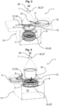
- a device for monitoring microbiological contamination designated as a whole by 1, has a closure holder 2 for a closure 3, which can be placed on a nutrient medium carrier 11, wherein the nutrient medium carrier 11 presents a nutrient medium 4, and an impactor 29, which is partially enclosed by a housing 13.
- the housing 13 has an opening 24 that can be closed with the closure holder 2, which covers an outside of the closure 3.
- the nutrient medium 4 is arranged behind a nozzle plate 25.
- the impactor 29 is connected to a pump 35 (not shown) via a suction connection 30.
- the pump thus sucks fluid from a fluid line 7 through the Nozzle plate 25 past the nutrient medium 4. Contaminants carried along are deposited on the nutrient medium 4 and can then be detected.
- the fluid line 7 can run at a process point within a clean room 20, where a clean room process is preferably carried out, and/or partially within the clean room 20.
- the clean room 20 is arranged above the fluid line 7.
- a fluid flow 17 from the clean room 20 can be discharged from a removal location 28, for example via the aforementioned pump 35, vertically via the fluid line 7 and a flow channel that defines a flow path of the fluid flow 17, and fed to a controlled environment 5.
- the fluid flow 17 is accelerated by the nozzle plate 25, which is designed with slots arranged in the circumferential direction with a clear opening dimension.
- a controlled environment 5 is delimited by an interface 6 which is first decontaminated by a gas or aerosol, in particular by a gas containing hydrogen peroxide, before the interface 6 is made accessible to the fluid stream 17 to be sampled or monitored and after a nutrient medium carrier 11, which does not contain a nutrient medium 4 for the decontamination, has been connected to the controlled environment 5.
- the gas or aerosol is supplied from the clean room 20 and/or from a separate decontamination source, in particular a decontamination device. After the Decontamination, the nutrient medium carrier 11 is exchanged for a nutrient medium carrier 11 with nutrient medium 4.
- the nutrient medium 4 is thus located in the controlled environment 5 and is presented by a holder 8 on a nutrient medium carrier 11.
- closure 3 of the sewing medium 4 is first removed via a transfer movement of the closure holder 2, which comprises an outer side of the closure 3.
- the fluid line 7 is only fluidically connected to the nutrient medium 4 after the closure 3 of the nutrient medium 4 has been removed.
- the fluid stream 17 can subsequently contact the nutrient medium 4 outside the clean room 20 in the decontaminated controlled environment 5.
- this embodiment provides that a receptacle 8 of the device 1 can be opened outwards via a transfer movement.
- a valve not shown in this figure is activated, whereby a backflow of the fluid stream 17 can be prevented.
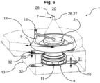
- Fig. 2 shows in contrast to Fig. 1 a further device 1 for monitoring microbiological contamination from the clean room 20.
- the closure receptacle 2 which is designed to receive the closure 3 of the nutrient medium 4, is attached to the nutrient medium 4 via a lifting device 32 or pivoting device 12, which enables the closure receptacle 2 to carry out a lifting movement 10 and/or a pivoting movement 9, whereby the closure 3 of the nutrient medium carrier 11 is removed or placed on the nutrient medium carrier 11.
- a fluid guide screen 18 which is designed to carry out a horizontal pivoting movement 9.
- the fluid line 7 can thus be closed by pivoting the fluid guide screen 18 from the side to a position above the nutrient medium carrier 11 after the closure receptacle 2 with the closure 3 has been pivoted to the side.
- closure 3 it is shown that, in contrast to the previous embodiment, it is possible for the closure 3 to be positioned in the controlled environment 5 outside the flow path of the fluid stream 17.
- Fig. 3 shows a three-dimensional representation of an alternative embodiment of a device 1 according to Fig. 2 .
- a removal chamber 31 is formed, which is formed by the housing 13.
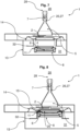
- Fig. 4 and Fig. 5 show a further embodiment according to the previous embodiments, with the difference that the housing 13 does not provide two, but only one placeholder for the closure receptacle 2, which surrounds the closure 3.
- the fluid guide plate 18 is not pivotable in this embodiment, but vertically movable in order to effect the connection of the fluid flow 17.
- Fig. 5 shows the fluid guide orifice 18 in the docked state.
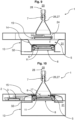
- Fig. 6 In contrast to the previous embodiments, it shows an elastic membrane 14 which is formed outside a flow path of the fluid flow 17 between a removal chamber 31 and the controlled environment 5 and forms a partial section of the housing 13.
- the impactor 29 can be removed and supplied via the removal chamber 31.
- the membrane 4 can be connected or is connected to the nutrient medium 4, in particular to the nutrient medium carrier 11, and is moved vertically in order to remove the closure 3 and/or to couple the fluid line 7 from the lifting device 32, which realizes a lifting movement 10 of the receptacle 8.
- Fig. 7 It is shown that the nutrient medium 4, which is positioned in the nutrient medium carrier 11, is not fluidically connected to the membrane 14. In this position, the nutrient medium 4 can be introduced into the controllable environment 5.
- the nutrient medium with the closure 3, in particular the nutrient medium carrier 11, is lifted to the closure holder 2 via the lifting device 32 become.
- a fluidic connection 27, which comprises a line piece 26, is established by means of a coupling 15, which carries out a relative movement between the nozzle plate 25 and the line piece 26.
- Fig. 9 shows that the nutrient medium carrier 11 is subsequently lowered again, whereby the elastic membrane 14 is also lowered via the connection of the nutrient medium carrier 11 with the elastic membrane 14.
- the closure receptacle 2 which comprises the closure 3 of the nutrient medium 4
- the closure receptacle 3 is placed outside the flow path of the fluid stream 17 within the controlled environment 5 via a pivoting movement 9 and the nutrient medium 4 is presented without the closure 3.
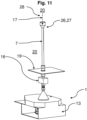
- Fig. 11 and 12 show the entire device 1, with the fluid line 7 running partially within the clean room 20.
- a particle counter 16 is shown, which in Fig. 11 in front of a floor plate 19 of the clean room 20, for example an isolator, and in Fig. 12 is positioned on the fluid line 7 within the clean room 20.
- the fluid flow 17 discharged from the clean room 20 via the fluid line 7 can be passed through the particle counter 16 before coming into contact with the nutrient medium 4.
- a side wall and/or a ceiling can also be used to guide the fluid line 7.
- a further variant not shown in this embodiment also consists in branching off the fluid flow 17, for example, outside the clean room 20, wherein the branched fluid flow 17 is also guided through the particle counter 16. becomes.
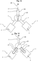
- Fig. 13 and Fig. 14 show a basic structure for monitoring microbiological contamination in a clean room 20, wherein, in contrast to the previous embodiments, two separate devices 1 are used, each of which is formed with a fluid line 7.
- the fluid flow 17, which is discharged from the clean room 20 for monitoring for microbiological contamination, can thus be directed into two different devices 1 either via an adjustable switch 23 or via a branch 22 of the fluid line 7.
- One of the two devices 1 presents a nutrient medium 4, which is contacted by the fluid flow 17 that is discharged from the clean room 20.
- the fluid flow 17 can be diverted, for example via the switch 23 or via the branch 22 of the fluid line 7, which is preferably designed with a valve 21, into the other device 1, into which a new nutrient medium 4 is inserted, preferably before the fluid flow 17 is diverted.
- the branch 22 of the fluid line 7, which is connected to the device 1 in which the nutrient medium 4 is to be changed, is blocked, for example, via the valve 21, which is in particular in a blocking position.
- the valve 21 is located as close as possible to the branch 22 in order to avoid dead spaces. It can therefore be said that continuous monitoring for microbiological contamination is possible.
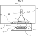
- Fig. 15 shows the modified device 1 according to Fig. 6 in an installed state in a clean room 20. It turns out that the controlled environment 5 is formed by the clean room 20 and that the membrane 14 is designed as a partial section of the clean room 20. In addition, it can be seen that the controlled environment 5, except for the fluid line 7, can be separated from the clean room 20.
- Fig. 16 shows a further device 1 according to the invention with an interface 6 which laterally delimits the controlled environment 5 and can be folded down via a pivoting movement 9, which is decontaminated at least on the inside before the interface 6 is made accessible for the fluid flow 17 to be monitored.
- a backflow prevention device is attached to the fluid line 7, which in this embodiment is designed as a ball valve 33 between the controlled environment 5 and the clean room 20.
- another backflow prevention device for example a diaphragm valve or another shut-off device known to the person skilled in the art, is attached instead of the ball valve 33.
- the decontamination agent required for decontamination is supplied to the interface 6 and the controlled environment 5 via a nozzle 34.
- closure 3 is removed from the nutrient medium carrier 11, which presents the nutrient medium 4, via a pivoting movement 9 of the closure receptacle 2, or is placed on the nutrient medium carrier 11 to close the nutrient medium 4.
- Figure 17 shows another device for monitoring microbiological contamination 1. It shows a Fluid line 7 or fluidic connection 27 with a particle counter 16, which takes fluid samples, here gas samples, at a sampling point 36 within the controlled environment 5, which in this embodiment is formed by the clean room 20 itself. In this case, a controlled fluid flow 17 is sucked in via a pump 35 arranged outside the clean room 20 (on the left in the picture) and thus fed to the particle counter 16.
- a pump 35 arranged outside the clean room 20 (on the left in the picture) and thus fed to the particle counter 16.
- the nutrient medium carrier 11 with the nutrient medium 4 presented therein is also located within the controlled environment 5 or clean room 20 parallel to the particle counter 16.
- the nutrient medium carrier 11 is connected to another pump 35 arranged outside the clean room 20 via another fluid line 7 or fluidic connection 27, via which the fluid flow 17 is sucked in, which in turn enables a defined contact of the fluid flow 17 of the clean room 20 with the nutrient medium 4.
- continuous monitoring for microbiological contamination is initially carried out via the particle counter 16, with the nutrient medium 4 initially closed by the closure 3 and thus not presented.
- no fluid flow 17 is initially sucked in by the pump 35 (in the right-hand image), which is connected to the nutrient medium carrier 11 via the fluid line 7.
- the closure 3 of the nutrient medium 4 is automatically removed from the closure holder 2 via a pivoting movement 9 and the nutrient medium 4 is presented.
- the fluid flow 17 is thus sucked in via the (right) pump 35, which is connected to the nutrient medium carrier 11 via the fluid line 7, which in turn contacts the presented nutrient medium 4.
- the nutrient medium 4 only in the fluid stream 17 is presented when contamination has been detected by the particle counter 16.
- the nutrient medium 4 can be examined after the presentation in a manner known per se to determine whether the contamination is capable of multiplying.
- the nutrient medium 4 is located outside the clean room 20 within a controlled environment 5.
- the fluid line 7 or fluidic connection 27 connects, according to Fig. 16 , the clean room 20 with a controlled environment 5, for example as in the previous embodiments, and is additionally designed with a switchable valve 21. As soon as the particle counter 16 has detected microbiological contamination, the valve 21 is switched to an open position, whereby the nutrient medium 4 is again automatically presented and contacted by the fluid flow 17.
- the nutrient medium 4 and the particle counter 16 are connected to a common pump 35.
- the nutrient medium 4 can thus be arranged in a switchable bypass to the fluid flow of the particle counter 16.
- the nutrient medium 4 can also be provided with an upstream, in particular decoupleable, fluid line 7 (cf. e.g. Fig. 12 ).
- a fluid stream 17 is discharged via a fluid line 7 from a clean room 20 into a controlled environment 5, wherein a nutrient medium 4 is presented in the controlled environment 5 and with which the fluid stream 17 is contacted and is then removed from the controlled environment 5 in such a way that a Cleanroom process does not have to be interrupted.
Landscapes
- Health & Medical Sciences (AREA)
- Life Sciences & Earth Sciences (AREA)
- Chemical & Material Sciences (AREA)
- Engineering & Computer Science (AREA)
- Wood Science & Technology (AREA)
- Organic Chemistry (AREA)
- Bioinformatics & Cheminformatics (AREA)
- Zoology (AREA)
- Biochemistry (AREA)
- General Health & Medical Sciences (AREA)
- Biomedical Technology (AREA)
- Molecular Biology (AREA)
- Analytical Chemistry (AREA)
- General Engineering & Computer Science (AREA)
- Sustainable Development (AREA)
- Genetics & Genomics (AREA)
- Biotechnology (AREA)
- Microbiology (AREA)
- Physics & Mathematics (AREA)
- General Physics & Mathematics (AREA)
- Immunology (AREA)
- Pathology (AREA)
- Epidemiology (AREA)
- Public Health (AREA)
- Apparatus Associated With Microorganisms And Enzymes (AREA)
Abstract
Erfindungsgemäß wird somit zur Überwachung mikrobiellen Wachstums vorgeschlagen, dass ein Fluidstrom über eine Fluidleitung aus einem Reinraum in eine kontrollierte Umgebung abgeführt wird, wobei in der kontrollierten Umgebung ein Nährmedium präsentiert und mit dem der Fluidstrom kontaktiert wird und anschließend so aus der kontrollierten Umgebung entnommen wird, dass ein Reinraumprozess nicht unterbrochen werden muss (Vgl. Fig. 10).According to the invention, it is therefore proposed to monitor microbial growth that a fluid flow is discharged from a clean room into a controlled environment via a fluid line, wherein a nutrient medium is presented in the controlled environment and with which the fluid flow is contacted and is then removed from the controlled environment in such a way that a clean room process does not have to be interrupted (see Fig. 10).
Description
Die Erfindung betrifft ein Verfahren zur Überwachung auf mikrobiologische Verunreinigungen in einem Reinraum, vorzugsweise Isolator, wobei ein Fluidstrom, insbesondere eine Luftströmung, aus dem Reinraum abgeführt wird.The invention relates to a method for monitoring microbiological contamination in a clean room, preferably an isolator, wherein a fluid flow, in particular an air flow, is discharged from the clean room.
Die Erfindung betrifft weiter eine Vorrichtung zur Überwachung auf mikrobiologische Verunreinigungen in einem Reinraum.The invention further relates to a device for monitoring microbiological contamination in a clean room.
Die Erfindung betrifft schließlich eine Verwendung, insbesondere innerhalb eines Reinraums und/oder innerhalb einer kontrollierten Umgebung, eines verpackten Nährmediums, insbesondere Impaktors, zur Präsentation des Nährmediums in einem Fluidstrom, wobei der Fluidstrom von einem Entnahmeort aus einem Reinraum, insbesondere Isolator, entnommen wurde, insbesondere wobei der Impaktor eine Düsenplatte hat, hinter der das Nährmedium angeordnet ist, wobei das Nährmedium, insbesondere hinter der Düsenplatte, vor Gebrauch durch einen Verschluss abgedeckt ist.Finally, the invention relates to a use, in particular within a clean room and/or within a controlled environment, of a packaged nutrient medium, in particular an impactor, for presenting the nutrient medium in a fluid stream, wherein the fluid stream was taken from a removal location in a clean room, in particular an isolator, in particular wherein the impactor has a nozzle plate behind which the nutrient medium is arranged, wherein the nutrient medium, in particular behind the nozzle plate, is covered by a closure before use.
Es ist aus der Praxis bekannt, einen Reinraum auf mikrobiologische Verunreinigungen mittels Probenentnahme zu überwachen.It is known from practice to monitor a cleanroom for microbiological contamination by taking samples.
Der Erfindung liegt die Aufgabe zugrunde, eine Überwachung auf mikrobiologische Verunreinigungen innerhalb eines Reinraums nahezu kontinuierlich durchzuführen, so dass ein Reinraumprozess nicht oder nur kurzzeitig unterbrochen werden muss.The invention is based on the object of monitoring for microbiological contamination within a clean room almost continuously, so that a clean room process does not have to be interrupted or only has to be interrupted for a short time.
Zur Lösung dieser Aufgabe schlägt die Erfindung die Merkmale von Anspruch 1 vor. Insbesondere wird somit erfindungsgemäß bei einem Verfahren zur Überwachung auf mikrobiologische Verunreinigungen vorgeschlagen, dass der Fluidstrom ein Nährmedium in einer kontrollierten, außerhalb des Reinraums angeordneten, vorzugsweise in einer durch eine Fluidleitung verbundenen Umgebung und/oder von dem Reinraum abtrennbaren Umgebung kontaktiert, wobei das Nährmedium zur Überwachung auf mikrobiologische Verunreinigungen verwendet wird.To solve this problem, the invention proposes the features of
Dabei kann beispielsweise vorgesehen sein, dass die kontrollierte Umgebung, bis auf eine Zuführung, beispielsweise der Fluidleitung, von dem Reinraum abtrennbar ist. Besonders vorteilhaft ist dabei, dass somit ein Entnahmeort, von dem der Fluidstrom aus dem Reinraum, vorzugsweise Isolator, abgeführt werden kann, relativ frei festgelegt werden kann.For example, it can be provided that the controlled environment can be separated from the clean room except for a supply line, for example the fluid line. It is particularly advantageous that a removal location from which the fluid flow can be discharged from the clean room, preferably the isolator, can be determined relatively freely.
Besonders vorteilhaft ist zudem, dass verhindert werden kann, dass Erzeugnisse im Reinraum, insbesondere durch ein direktes Eingreifen in einen im Reinraum ablaufenden Reinraumprozess, kontaminiert werden. Somit kann ein praktisch unbegrenzter Austausch des Nährmediums ohne aktive Schleuse erfolgen, ohne dass der Reinraum anschließend dekontaminiert wird, beispielsweise dadurch, dass die kontrollierte Umgebung gegenüber dem Reinraum während des Austauschs abgeschlossen wird und die fluidische Verbindung nach dem Austausch für eine Messung hergestellt wird. Eine konstruktiv einfache Ausgestaltung kann eine Anordnung der kontrollierten Umgebung außerhalb des Reinraums sein. Dies kann eine Zugänglichkeit für den Austausch verbessern.Another particularly advantageous feature is that it is possible to prevent products in the cleanroom from becoming contaminated, particularly by directly intervening in a cleanroom process taking place in the cleanroom. This means that the nutrient medium can be exchanged practically without an active lock and without the cleanroom being decontaminated afterwards, for example by closing off the controlled environment from the cleanroom during the exchange and establishing the fluidic connection for measurement after the exchange. A structurally simple design can be to arrange the controlled environment outside the cleanroom. This can improve accessibility for the exchange.
Ein Reinraumprozess kann dabei beispielsweise eine aseptische Abfüllung und/oder ein Verschließen und/oder eine Analyse von pharmazeutischen Erzeugnissen sein.A cleanroom process can, for example, be aseptic filling and/or sealing and/or analysis of pharmaceutical products.
Das Nährmedium kann dabei beispielsweise fest, insbesondere als Agar, oder flüssig, insbesondere als Bouillon, sein.The nutrient medium can be, for example, solid, in particular agar, or liquid, in particular broth.
Der Fluidstrom kann dabei beispielsweise horizontal und/oder vertikal oder schräg aus dem Reinraum abgeführt werden.The fluid flow can be horizontal and/or vertically or diagonally out of the cleanroom.
Allgemein kann der Reinraum bei einer vorteilhaften Anwendung der Erfindung beispielsweise als Isolator ausgebildet sein.In general, in an advantageous application of the invention, the clean room can be designed, for example, as an isolator.
Besonders vorteilhaft ist dabei, dass über eine Kontaktierung des aus dem Reinraum abgeführten Fluidstroms mit dem Nährmedium in einer kontrollierten Umgebung verschiedene Dekontaminierungsprozesse minimiert werden.What is particularly advantageous is that various decontamination processes are minimized by bringing the fluid flow discharged from the clean room into contact with the nutrient medium in a controlled environment.
Zudem ist besonders vorteilhaft, dass das Risiko einer Kontaminierung der Erzeugnisse, die im Reinraum während eines Reinraumprozesses hergestellt werden, ebenfalls minimiert werden kann.Another advantage is that the risk of contamination of products manufactured in the cleanroom during a cleanroom process can also be minimized.
Da die Überwachung auf mikrobiologische Verunreinigungen außerhalb des Reinraums stattfindet, ist besonders vorteilhaft, dass hierdurch eine nahezu kontinuierliche oder wiederkehrende Messung möglich ist, ohne dass der Reinraumprozess länger unterbrochen werden muss. Hierdurch können ebenfalls besonders vorteilhaft schnellere und kostengünstigere, mit geringerem Ausschuss zu realisierende Prozessabläufe generiert werden.Since monitoring for microbiological contamination takes place outside the cleanroom, it is particularly advantageous that this enables almost continuous or recurring measurement without the cleanroom process having to be interrupted for any length of time. This also makes it particularly advantageous to generate faster and more cost-effective process sequences with less waste.
Weiterhin kann beispielsweise vorgesehen sein, dass wenigstens eine Kenngröße, insbesondere ein Volumenstrom des Fluidstroms, erfasst wird und/oder dass die Kenngröße, insbesondere aufgrund der Erfassung, reguliert wird.Furthermore, it can be provided, for example, that at least one characteristic variable, in particular a volume flow of the fluid flow, is detected and/or that the characteristic variable is regulated, in particular on the basis of the detection.
Bei einer weiteren vorteilhaften Ausgestaltung kann vorgesehen sein, dass eine die kontrollierte Umgebung begrenzende Schnittstelle dekontaminiert wird, insbesondere bevor die Schnittstelle für den zu überwachenden Fluidstrom zugänglich gemacht wird.In a further advantageous embodiment, it can be provided that an interface delimiting the controlled environment is decontaminated, in particular before the interface is made accessible to the fluid flow to be monitored.
Die kontrollierte Umgebung begrenzende Schnittstelle kann dabei beispielsweise das über eine Andocköffnung oder eine Zugangsöffnung ankoppelbare und/oder austauschbare Nährmedium sein.The interface delimiting the controlled environment can This could, for example, be the nutrient medium that can be coupled and/or exchanged via a docking opening or an access opening.
Besonders vorteilhaft ist dabei, dass somit sichergestellt werden kann, dass möglicherweise nachweisbare mikrobiologische Verunreinigungen eindeutig dem aus dem Reinraum abgeführten Fluidstrom zugeordnet werden können und nicht durch eine Kontaminierung der Schnittstelle entstehen.What is particularly advantageous is that it can be ensured that any detectable microbiological contamination can be clearly attributed to the fluid flow discharged from the cleanroom and does not arise from contamination of the interface.
Somit kann vorteilhaft beispielsweise vermieden werden, dass vermehrungsfähige Organismen an der Schnittstelle, die aufgrund von Verunreinigungen außerhalb des Reinraums entstanden sind, als falsch positive Befunde zu einem unnötigen Ausschuss der während des Reinraumprozesses hergestellten Erzeugnisse resultieren.This makes it possible to advantageously avoid, for example, the occurrence of organisms capable of reproduction at the interface that have arisen due to contamination outside the cleanroom, which could result in false positive findings and unnecessary rejection of the products manufactured during the cleanroom process.
Bei einer weiteren vorteilhaften Ausgestaltung kann vorgesehen sein, dass an der Fluidleitung eine Verzweigung oder eine Weiche ausgebildet ist, insbesondere wobei der Fluidstrom steuerbar ist.In a further advantageous embodiment, it can be provided that a branch or a switch is formed on the fluid line, in particular wherein the fluid flow is controllable.
Besonders vorteilhaft ist dabei, dass somit beispielsweise zwei separate Vorrichtungen zur Überwachung auf mikrobiologische Verunreinigungen verwendet werden können, die wiederum eine kontinuierliche Überwachung auf mikrobiologische Verunreinigungen im Reinraum ermöglichen. Diese können zeitlich überlappend oder zeitlich abwechselnd betrieben werden.What is particularly advantageous is that, for example, two separate devices can be used to monitor for microbiological contamination, which in turn enables continuous monitoring for microbiological contamination in the clean room. These can be operated at overlapping times or alternately.
Dabei kann beispielsweise vorgesehen sein, dass ein Nährmedium in einer der beiden Vorrichtungen präsentiert und von dem aus dem Reinraum abgeführten Fluidstrom über die Fluidleitung kontaktiert wird. Sobald das Nährmedium beispielsweise in einen Inkubator gelegt und somit getauscht werden soll, kann ein Nährmedium in die andere Vorrichtung eingelegt und die Fluidleitung bzw. der Fluidstrom entsprechend umgelenkt werden. Somit kann vorteilhaft die Entnahme des einen Nährmediums simultan zur fortlaufenden Überwachung auf mikrobiologische Verunreinigungen des Fluidstroms aus dem Reinraum über das andere Nährmedium stattfinden.For example, it can be provided that a nutrient medium is presented in one of the two devices and is contacted by the fluid flow discharged from the clean room via the fluid line. As soon as the nutrient medium is to be placed in an incubator and thus exchanged, a nutrient medium is placed in the other device and the fluid line or the fluid flow is diverted accordingly. This makes it advantageous to remove one nutrient medium simultaneously with the continuous monitoring of the fluid flow from the clean room for microbiological contamination via the other nutrient medium.
Bei einer weiteren vorteilhaften Ausgestaltung kann vorgesehen sein, dass zur Dekontamination der Schnittstelle und/oder der kontrollierten Umgebung ein Dekontaminationsmittel, insbesondere ein Gas bzw. Aerosol, vorzugsweise Wasserstoffperoxid, zugeführt wird, insbesondere wobei das Gas bzw. Aerosol aus dem Reinraum und/oder aus einer separaten Dekontaminationsquelle zugeführt wird.In a further advantageous embodiment, it can be provided that a decontamination agent, in particular a gas or aerosol, preferably hydrogen peroxide, is supplied for decontamination of the interface and/or the controlled environment, in particular wherein the gas or aerosol is supplied from the clean room and/or from a separate decontamination source.
Besonders vorteilhaft ist dabei, dass das zur Dekontamination verwendete Gas bzw. Aerosol somit an unterschiedlichen Stellen der Schnittstelle zugeführt werden kann und die für die Begasung üblichen Loop-Verfahren anwendbar sind.A particular advantage is that the gas or aerosol used for decontamination can be supplied to different points on the interface and the loop procedures commonly used for fumigation can be used.
Beispielsweise kann dabei vorgesehen sein, dass das Gas bzw Aerosol in den Reinraum strömt, wobei die Dekontamination der Schnittstelle beispielsweise über den dem Reinraum abgeführten Fluidstrom erfolgt.For example, it can be provided that the gas or aerosol flows into the clean room, whereby the decontamination of the interface takes place, for example, via the fluid flow discharged from the clean room.
Bei einer weiteren vorteilhaften Ausgestaltung kann vorgesehen sein, dass der Fluidstrom an einer Prozessstelle innerhalb des Reinraums, an der vorzugsweise ein Reinraumprozess durchgeführt wird, aus dem Reinraum abgeführt wird, und/oder wobei der Fluidstrom in einer Fluidleitung, welche zumindest teilweise innerhalb des Reinraums verläuft, dem Nährmedium zugeführt wird. Besonders vorteilhaft ist dabei, dass über eine direkte Leitung des Fluidstroms eine kontinuierliche Messung, beispielsweise der Reinraumluft, bereits während des Reinraumprozesses möglich ist, wodurch der Reinraumprozess nicht oder nur kurzzeitig unterbrochen werden muss.In a further advantageous embodiment, it can be provided that the fluid flow is discharged from the clean room at a process point within the clean room, at which a clean room process is preferably carried out, and/or wherein the fluid flow is fed to the nutrient medium in a fluid line which runs at least partially within the clean room. It is particularly advantageous in this case that a continuous measurement, for example of the clean room air, is already possible during the clean room process via a direct line of the fluid flow, whereby the clean room process does not need to be interrupted or only needs to be interrupted for a short time.
Bei einer weiteren vorteilhaften Ausgestaltung kann vorgesehen sein, dass der Fluidstrom durch einen Partikelzähler zur Erfassung einer Partikelanzahl und/oder Partikelgröße geführt wird, insbesondere wobei anschließend derselbe Fluidstrom zum Nährmedium geführt wird und/oder wobei ein Teilvolumen des Fluidstroms abgezweigt wird, insbesondere wobei der abgezweigte Fluidstrom an einen Partikelzähler zur Erfassung einer Partikelanzahl überführt wird und/oder wobei die Abzweigung außerhalb des Reinraums stattfindet.In a further advantageous embodiment, it can be provided that the fluid flow is guided through a particle counter for detecting a particle number and/or particle size, in particular wherein the same fluid flow is subsequently guided to the nutrient medium and/or wherein a partial volume of the fluid flow is branched off, in particular wherein the branched fluid flow is transferred to a particle counter for detecting a particle number and/or wherein the branching takes place outside the clean room.
Die Abzweigung des Fluidstroms kann dabei beispielsweise kontrolliert über regulierbare und/oder steuerbare Düsen erfolgen.The branching of the fluid flow can, for example, be controlled via adjustable and/or controllable nozzles.
Dabei kann beispielsweise vorgesehen sein, dass der Partikelzähler kurz vor der kontrollierten Umgebung an einer Fluidleitung angeordnet ist. Weiterhin kann beispielsweise vorgesehen sein, dass der Partikelzähler außerhalb der kontrollierten Umgebung innerhalb des Reinraums an einer Fluidleitung angeordnet ist.It can be provided, for example, that the particle counter is arranged on a fluid line shortly before the controlled environment. It can also be provided, for example, that the particle counter is arranged on a fluid line outside the controlled environment within the clean room.
Besonders vorteilhaft ist dabei, dass die Überwachung auf Verunreinigungen durch funktionell unterschiedlichen Methoden um quantitative Angaben, beispielsweise Anzahl und/oder Größe der Verunreinigungen, ergänzt werden kann. Ein Partikelzähler kann auch zur genaueren Eingrenzung eines Zeitpunktes der Verunreinigung herangezogen werden.A particularly advantageous feature is that monitoring for contamination using functionally different methods can be supplemented with quantitative information, such as the number and/or size of the contamination. A particle counter can also be used to more precisely determine the point in time at which contamination occurred.
Vorteilhaft ist zudem, dass über den Partikelzähler die Anzahl möglicher Verunreinigungen bestimmt werden kann, während über das Nährmedium detektiert werden kann, welche Art der Verunreinigung vorliegt.Another advantage is that the particle counter can be used to determine the number of possible contaminations, while the nutrient medium can be used to detect which type of contamination is present.
Vorteilhaft ist somit, dass eine solche Kombination eine schnellere Reaktionszeit zur Unterbrechung des Reinraumprozesses ermöglicht.The advantage is that such a combination faster reaction time to interrupt the cleanroom process.
Bei einer weiteren vorteilhaften Ausgestaltung kann vorgesehen sein, dass das Nährmedium von außen in die kontrollierte Umgebung eingebracht und an einer Aufnahme positioniert wird, insbesondere wobei nach dem Einbringen die kontrollierte Umgebung dekontaminiert wird.In a further advantageous embodiment, it can be provided that the nutrient medium is introduced into the controlled environment from the outside and positioned on a holder, in particular wherein the controlled environment is decontaminated after introduction.
Somit ist es beispielsweise möglich, das Nährmedium während eines Reinraumprozesses auszutauschen.This makes it possible, for example, to exchange the nutrient medium during a clean room process.
Besonders vorteilhaft ist dabei, dass das Nährmedium somit während eines Reinraumprozesses gewechselt bzw. ausgetauscht werden kann und der Reimraumprozess demnach unabhängig von dem Einbringen des Nährmediums ohne Risiko einer Kontaminierung des Reinraums fortgeführt werden kann. Demnach ist ebenfalls vorteilhaft, dass der Reinraumprozess bei einer Kontaminierung der kontrollierten Umgebung fortgeführt werden kann.It is particularly advantageous that the nutrient medium can be changed or exchanged during a clean room process and the clean room process can therefore be continued independently of the introduction of the nutrient medium without the risk of contamination of the clean room. It is therefore also advantageous that the clean room process can be continued if the controlled environment is contaminated.
Bei einer vorteilhaften Ausgestaltung kann vorgesehen sein, dass vor einem Austausch des Nährmediums eine Rückströmverhinderung, insbesondere ein Ventil, vorzugsweise zwischen der kontrollierten Umgebung und dem Reinraum aktiviert wird.In an advantageous embodiment, it can be provided that a backflow prevention device, in particular a valve, is activated preferably between the controlled environment and the clean room before the nutrient medium is exchanged.
Dabei kann beispielsweise vorgesehen sein, ein Ventil zu verwenden, welches minimale Kontaminierungsfläche bietet, um die Wahrscheinlichkeit einer Kontaminierung schlecht dekontaminierbarer Oberflächen zu verhindern.For example, it may be intended to use a valve that offers minimal contamination surface in order to prevent the likelihood of contamination of surfaces that are difficult to decontaminate.
Besonders vorteilhaft ist dabei, dass eine während des Austauschs des Nährmediums mögliche Kontaminierung der kontrollierten Umgebung zu keiner Kontaminierung der Fluidleitung durch eine Rückströmung des kontaminierten Fluidstroms führt.What is particularly advantageous is that any contamination of the controlled environment that may occur during the exchange of the nutrient medium does not lead to contamination of the fluid line due to backflow of the contaminated fluid stream.
Bei einer weiteren vorteilhaften Ausgestaltung kann vorgesehen sein, dass nach dem Einbringen ein Verschluss des Nährmediums entfernt und in der kontrollierten Umgebung aufbewahrt wird, insbesondere wobei der Verschluss außerhalb eines Strömungswegs des Fluidstroms aufbewahrt wird.In a further advantageous embodiment, it can be provided that after introduction, a closure of the nutrient medium is removed and stored in the controlled environment, in particular wherein the closure is stored outside a flow path of the fluid stream.
Hierbei kann beispielsweise vorgesehen sein, dass das Nährmedium beispielsweise an eine Austrittöffnung, einen Austrittraum oder einen Austrittskegel des Fluidstroms gepresst wird.In this case, it can be provided, for example, that the nutrient medium is pressed against an outlet opening, an outlet chamber or an outlet cone of the fluid flow.
Besonders vorteilhaft ist dabei, dass der abgenommene Verschluss die Strömungseigenschaften des Fluidstroms somit nicht negativ beeinflusst, die beispielsweise in einer möglicherweise entstehenden turbulenten Strömung des Fluidstroms resultieren. Zudem ist hierdurch vorteilhaft verhindert, dass mögliche an dem Verschluss anhaftende Verunreinigungen von dem Fluidstrom mitgerissen werden und das Messergebnis verfälschen oder durch den Fluidstrom herangeführte Mikroorganismen am Verschluss oder einer Verschlussaufnahme anhaften und somit nicht dem Nährmedium überführt werden.It is particularly advantageous that the removed closure does not negatively influence the flow properties of the fluid flow, which could result in a potentially turbulent flow of the fluid flow, for example. This also advantageously prevents any impurities adhering to the closure from being carried along by the fluid flow and distorting the measurement result, or microorganisms brought in by the fluid flow from adhering to the closure or a closure holder and thus not being transferred to the nutrient medium.
Die Verschlussaufnahme ist dabei insbesondere dazu ausgebildet, eine Außenseite eines Verschlusses zu umgreifen. Wird die Außenseite des Verschlusses hierbei vollständig oder praktisch vollständig von der Verschlussaufnahme abgedeckt, so kann eine Kontamination durch die Außenseite ausgeschlossen (bzw. praktisch ausgeschlossen) werden. Beispielsweise kann dies nach Art eines Rapid Transfer Ports realisiert sein.The closure receptacle is designed in particular to encompass the outside of a closure. If the outside of the closure is completely or practically completely covered by the closure receptacle, contamination from the outside can be excluded (or practically excluded). For example, this can be implemented in the manner of a rapid transfer port.
Alternativ oder zusätzlich sind zur Lösung der genannten Aufgabe erfindungsgemäß die Merkmale des nebengeordneten, auf ein Verfahren gerichteten Anspruchs vorgesehen. Insbesondere wird somit zur Lösung der genannten Aufgabe bei einem Verfahren zur Überwachung auf mikrobiologische Verunreinigungen in einem Reinraum, wobei ein Fluidstrom, insbesondere eine Luftströmung, aus dem Reinraum abgeführt wird, wobei der Fluidstrom ein Nährmedium kontaktiert, wobei das Nährmedium zur Überwachung auf mikrobiologische Verunreinigungen verwendet wird, insbesondere wie zuvor beschrieben, vorgeschlagen, dass eine Fluidleitung, die den Fluidstrom zum Nährmedium bringt, an das Nährmedium angeschlossen wird, nachdem ein Verschluss des Nährmediums entfernt wurde.Alternatively or additionally, the features of the independent claim directed to a method are provided according to the invention to solve the problem mentioned. In particular, the problem mentioned is solved in a Method for monitoring for microbiological contamination in a clean room, wherein a fluid flow, in particular an air flow, is discharged from the clean room, wherein the fluid flow contacts a nutrient medium, wherein the nutrient medium is used for monitoring for microbiological contamination, in particular as previously described, proposed that a fluid line which brings the fluid flow to the nutrient medium is connected to the nutrient medium after a closure of the nutrient medium has been removed.
Dabei kann beispielsweise vorgesehen sein, dass das Anschließen der Fluidleitung an das Nährmedium ein mechanisches Verbinden und/oder ein Öffnen einer Absperrung ist.For example, it can be provided that the connection of the fluid line to the nutrient medium is a mechanical connection and/or an opening of a barrier.
Besonders vorteilhaft ist dabei, dass ein kontrollierter Raum von dem Reinraum gebildet werden kann und somit auf einen von dem Reinraum separat angeordneten kontrollierten Raum verzichtet werden kann.What is particularly advantageous is that a controlled room can be formed from the clean room, thus eliminating the need for a controlled room arranged separately from the clean room.
Vorteilhaft ist zudem, dass hierdurch ein Rückströmen eines möglicherweise kontaminierten Fluidstroms verhindert wird, da die Fluidleitung erst an das Nährmedium angeschlossen wird, wenn das Nährmedium verschlossen ist.Another advantage is that this prevents backflow of a potentially contaminated fluid stream, since the fluid line is only connected to the nutrient medium when the nutrient medium is closed.
Bei einer weiteren vorteilhaften Ausgestaltung kann vorgesehen sein, dass der Verschluss über eine Transferbewegung, insbesondere eine vorzugsweise horizontale Schwenkbewegung und/oder eine Hubbewegung, entfernt wird.In a further advantageous embodiment, it can be provided that the closure is removed via a transfer movement, in particular a preferably horizontal pivoting movement and/or a lifting movement.
Besonders vorteilhaft ist dabei, dass der Verschluss somit problemlos in einen Bereich außerhalb des Strömungswegs des Fluidstroms bewegt und gleichzeitig von dem Nährmedium entfernt werden kann.A particular advantage is that the closure can thus be easily moved to an area outside the flow path of the fluid stream and at the same time removed from the nutrient medium.
Bei einer weiteren vorteilhaften Ausgestaltung kann vorgesehen sein, dass das Nährmedium, insbesondere auf einem Nährmediumsträger, zur Entfernung und/oder zur Anbringung des Verschlusses und/oder zur Ankopplung der Fluidleitung von einer Hebevorrichtung, insbesondere die mit einer Membrane verbindbar oder verbunden ist, vorzugsweise vertikal bewegt wird.In a further advantageous embodiment, it can be provided that the nutrient medium, in particular on a nutrient medium carrier, is moved preferably vertically by a lifting device, in particular which is connectable or connected to a membrane, for removing and/or attaching the closure and/or for coupling the fluid line.
Der Nährmediumsträger kann dabei beispielsweise ein Gehäuse für das Nährmedium bilden.The nutrient medium carrier can, for example, form a housing for the nutrient medium.
Dabei kann beispielsweise vorgesehen sein, dass die Membrane einen Raum, in den der Verschluss beispielsweise verschwenkt wird, von einem Außenraum zu trennen.In this case, it can be provided, for example, that the membrane separates a space into which the closure is pivoted, for example, from an external space.
Besonders vorteilhaft ist dabei, dass an diesem Außenraum eine Dekontaminierung erfolgen kann.What is particularly advantageous is that decontamination can be carried out in this outdoor area.
Bei einer weiteren vorteilhaften Ausgestaltung kann vorgesehen sein, dass das Nährmedium nach erfolgter Kontaktierung mit dem Fluidstrom aus der kontrollierten Umgebung entfernt wird, insbesondere durch eine Bewegung der Aufnahme.In a further advantageous embodiment, it can be provided that the nutrient medium is removed from the controlled environment after contact with the fluid flow, in particular by a movement of the receptacle.
Dabei kann beispielsweise vorgesehen sein, dass die Aufnahme horizontal und/oder vertikal bewegt wird.For example, it can be provided that the recording is moved horizontally and/or vertically.
Beispielsweise kann zudem vorgesehen sein, dass das Nährmedium nach erfolgter Kontaktierung mit dem Fluidstrom mit dem Verschluss verschlossen wird, bevor das Nährmedium aus der kontrollierten Umgebung entfernt wird.For example, it may also be provided that the nutrient medium is closed with the closure after contact with the fluid stream before the nutrient medium is removed from the controlled environment.
Besonders vorteilhaft ist dabei, dass hierdurch eine Kontaminierung des kontrollierten Raums weitestgehend verhindert werden kann.A particular advantage is that this largely prevents contamination of the controlled space.
Vorteilhaft ist somit, dass das Nährmedium somit problemlos entfernt und beispielsweise einem Inkubator zugeführt werden kann.The advantage is that the nutrient medium can be easily removed and, for example, fed into an incubator.
Bei einer weiteren vorteilhaften Ausgestaltung kann vorgesehen sein, dass in dem Fluidstrom oder einem weiteren Fluidstrom eine Partikeldetektion durchgeführt wird und ein oder das Nährmedium erst und/oder automatisch in dem Fluidstrom präsentiert wird, wenn die Partikeldetektion ein vorzugsweise vermehrungsfähiges und/oder lebendes Objekt detektiert hat, insbesondere durch Umleiten des Fluidstroms, Öffnen einer den Fluidstrom leitenden Fluidleitung und/oder Starten des Fluidstroms.In a further advantageous embodiment, it can be provided that particle detection is carried out in the fluid stream or a further fluid stream and a or the nutrient medium is only and/or automatically presented in the fluid stream when the particle detection has detected a preferably reproducible and/or living object, in particular by diverting the fluid stream, opening a fluid line conducting the fluid stream and/or starting the fluid stream.
Besonders vorteilhaft ist dabei, dass das Nährmedium somit insbesondere erst dann geöffnet, verwendet und/oder verbraucht wird, wenn von dem Partikelzähler nachweislich mikrobiologische Verunreinigungen detektiert werden konnten.What is particularly advantageous is that the nutrient medium is only opened, used and/or consumed when the particle counter has demonstrably detected microbiological contamination.
Somit kann beispielsweise ebenfalls vorteilhaft ein unnötiges Austrocknen des Nährmediums verhindert werden.This can also advantageously prevent unnecessary drying out of the nutrient medium.
Alternativ oder zusätzlich sind zur Lösung der genannten Aufgabe erfindungsgemäß die Merkmale des nebengeordneten, auf eine Vorrichtung gerichteten Anspruchs vorgesehen. Insbesondere wird somit erfindungsgemäß zur Lösung der genannten Aufgabe zur Überwachung auf mikrobiologische Verunreinigungen in einem Reinraum vorgeschlagen, dass eine Einhausung, die eine, beispielsweise die bereits erwähnte, kontrollierte Umgebung umschließt, eine, beispielsweise die bereits erwähnte, Aufnahme zum Präsentieren eines, beispielsweise des bereits erwähnten, Nährmediums in der kontrollierten Umgebung, eine fluidische Anbindung zur Verbindung mit dem Reinraum und eine Schnittstelle, welche die kontrollierte Umgebung begrenzt, insbesondere zur Bereitstellung des Nährmediums, umfasst.Alternatively or additionally, the features of the independent claim directed to a device are provided according to the invention to solve the problem mentioned. In particular, the invention proposes to solve the problem mentioned for monitoring microbiological contamination in a clean room that an enclosure which encloses a controlled environment, for example the one already mentioned, comprises a receptacle, for example the one already mentioned, for presenting a nutrient medium, for example the one already mentioned, in the controlled environment, a fluidic connection for connection to the clean room and an interface which delimits the controlled environment, in particular for providing the nutrient medium.
Besonders vorteilhaft ist dabei, dass somit die Vorteile des bereits beanspruchten Verfahrens realisiert werden können.What is particularly advantageous is that the advantages of the already claimed method can thus be realized.
Bei einer vorteilhaften Ausgestaltung kann vorgesehen sein, dass die fluidische Anbindung eine Verzweigung oder eine Weiche hat, die dazu ausgebildet ist, einen Fluidstrom umzulenken.In an advantageous embodiment, it can be provided that the fluidic connection has a branch or a switch which is designed to divert a fluid flow.
Besonders vorteilhaft ist dabei, dass ein Fluidstrom, der insbesondere aus dem Reinraum abgeführt wird, kontinuierlich, beispielsweise durch die Verwendung von zwei separaten kontrollierten Umgebungen, in denen ein Nährmedium präsentiert werden kann, auf mikrobiologische Verunreinigungen überwacht werden kann.What is particularly advantageous is that a fluid stream, which is discharged in particular from the clean room, can be continuously monitored for microbiological contamination, for example by using two separate controlled environments in which a nutrient medium can be presented.
Bei einer weiteren vorteilhaften Ausgestaltung kann vorgesehen sein, dass eine Dekontaminationsvorrichtung ausgebildet ist, durch welche zumindest die Schnittstelle, insbesondere die kontrollierte Umgebung, dekontaminierbar ist.In a further advantageous embodiment, it can be provided that a decontamination device is formed, by means of which at least the interface, in particular the controlled environment, can be decontaminated.
Dabei kann beispielsweise vorgesehen sein, dass die Dekontaminationsvorrichtung ausgebildet ist, zur Dekontaminierung der Schnittstelle ein Dekontaminationsmittel, insbesondere Gas bzw. Aerosol, beispielsweise Wasserstoffperoxid, beispielsweise aus dem Reinraum und/oder aus einer separaten Dekontaminationsquelle der Schnittstelle zuzuführen.In this case, it can be provided, for example, that the decontamination device is designed to supply a decontamination agent, in particular gas or aerosol, for example hydrogen peroxide, for example from the clean room and/or from a separate decontamination source to the interface in order to decontaminate the interface.
Besonders vorteilhaft ist dabei, dass es somit nahezu verhinderbar ist, dass mikrobiologische Verunreinigungen durch eine kontaminierte Schnittstelle entsteht. Hierdurch ist wiederum vorteilhaft, dass mögliche detektierte mikrobiologische Verunreinigungen mit hoher Wahrscheinlichkeit durch eine Kontaminierung des Reinraums entstanden sind.What is particularly advantageous is that it is almost impossible for microbiological contamination to occur through a contaminated interface. This in turn has the advantage that any microbiological contamination detected is highly likely to have been caused by contamination of the clean room.
Bei einer weiteren vorteilhaften Ausgestaltung kann vorgesehen sein, dass die Schnittstelle als Teil der Einhausung, insbesondere als Teil einer Verschlussvorrichtung der Einhausung ausgebildet ist.In a further advantageous embodiment, provision can be made that the interface is designed as part of the housing, in particular as part of a locking device of the housing.
Dabei kann beispielsweise vorgesehen sein, dass die Schnittstelle von einem Verschluss des Nährmediums gebildet wird.For example, it can be provided that the interface is formed by a closure of the nutrient medium.
Vorteilhaft ist dabei, dass somit die Möglichkeit besteht, das Nährmedium vor einer Entnahme zu verschließen.The advantage here is that it is possible to close the culture medium before removal.
Bei einer weiteren vorteilhaften Ausgestaltung kann vorgesehen sein, dass die kontrollierte Umgebung eine Zuleitung und/oder eine Ableitung für ein Dekontaminationsmittel der Dekontaminationsvorrichtung hat und/oder wobei die Dekontaminationsvorrichtung als Teil der Vorrichtung ausgebildet ist.In a further advantageous embodiment, it can be provided that the controlled environment has a supply line and/or a discharge line for a decontamination agent of the decontamination device and/or wherein the decontamination device is designed as part of the device.
Besonders vorteilhaft ist dabei, dass somit unterschiedliche Methoden zur Dekontaminierung, beispielsweise der Schnittstelle, anwendbar sind.What is particularly advantageous is that different methods for decontamination, for example of the interface, can be used.
Dabei kann beispielsweise vorgesehen sein, dass das Dekontaminationsmittel über einen Fluidstrom, welcher aus dem Reinraum abgeführt wird, der kontrollierten Umgebung zugeführt wird.For example, it can be provided that the decontamination agent is supplied to the controlled environment via a fluid stream which is discharged from the clean room.
Bei einer weiteren vorteilhaften Ausgestaltung kann vorgesehen sein, dass die Aufnahme in der kontrollierten Umgebung ausgebildet ist, insbesondere wobei die Aufnahme dazu eingerichtet ist, die Vorrichtung nach außen zu öffnen.In a further advantageous embodiment, it can be provided that the receptacle is formed in the controlled environment, in particular wherein the receptacle is designed to open the device to the outside.
Die Aufnahme kann dabei beispielsweise horizontal und/oder vertikal beweglich sein.The holder can, for example, be movable horizontally and/or vertically.
Zudem ist vorteilhaft, dass ein Wechsel des Nährmediums somit unabhängig eines im Reinraum ablaufenden Reinraumprozesses durchgeführt werden kann.It is also advantageous that a change of the nutrient medium can be carried out independently of a cleanroom process taking place in the cleanroom.
Bei einer weiteren vorteilhaften Ausgestaltung kann vorgesehen sein, dass die Vorrichtung eine Hebevorrichtung aufweist.In a further advantageous embodiment, it can be provided that the device has a lifting device.
Dabei kann beispielsweise vorgesehen sein, dass die Aufnahme vertikal beweglich ist.For example, it can be provided that the holder is vertically movable.
Besonders vorteilhaft ist dabei, dass somit beispielsweise eine einfache Möglichkeit zur Entnahme des Nährmediums realisiert ist. Bei einer Ausgestaltung, für die eigenständig Schutz beansprucht wird, kann erfindungsgemäß vorgesehen sein, dass zur Überwachung auf mikrobiologische Verunreinigungen in einem Reinraum, insbesondere zur Durchführung eines bereits genannten Verfahrens und/oder nach einem der auf eine Vorrichtung gerichteten Ansprüche, umfassend die oder eine Aufnahme zum Präsentieren eines oder des Nährmediums, eine fluidische Anbindung, insbesondere von einem Entnahmeort im Reinraum, die an das Nährmedium ankoppelbar ist und ein Mittel zum vorzugsweise ferngesteuerten Entfernen eines Verschlusses des Nährmediums bevor die fluidische Anbindung angekoppelt ist.It is particularly advantageous that, for example, a simple possibility for removing the nutrient medium is thus realized. In an embodiment for which independent protection is claimed, it can be provided according to the invention that for monitoring for microbiological contamination in a clean room, in particular for carrying out a method already mentioned and/or according to one of the claims directed to a device, comprising the or a receptacle for presenting a or the nutrient medium, a fluidic connection, in particular from a removal location in the clean room, which can be coupled to the nutrient medium and a means for preferably remotely removing a closure of the nutrient medium before the fluidic connection is coupled.
Von Vorteil ist dabei, dass eine Auswechslung des Nährmediums, das mit einem Verschlussgekapselt bereitgestellt werden kann, durchführbar ist, ohne dass ein Inneres des Reinraums gestört werden muss.The advantage here is that the nutrient medium, which can be provided with a closure cap, can be replaced without disturbing the interior of the clean room.
Das Entfernen kann vorzugsweise automatisiert oder manuell erfolgen. Dies kann beispielsweise vollautomatisch oder manuell über eine Fernsteuerung erfolgen.Removal can preferably be automated or manual. This can be done, for example, fully automatically or manually via remote control.
Eine Ankopplung kann dabei beispielsweise ein mechanisches Verbinden zwischen dem Nährmedium und der fluidischen Anbindung oder beispielsweise das Öffnen einer Absperrung sein.A coupling can be, for example, a mechanical connection between the nutrient medium and the fluidic connection or, for example, the opening of a barrier be.
Besonders vorteilhaft ist dabei, dass somit verhindert werden kann, dass ein kontaminierter Fluidstrom in den Reinraum strömt.A particularly advantageous feature is that it can prevent a contaminated fluid stream from flowing into the clean room.
Vorteilhaft ist zudem, dass die kontrollierte Umgebung somit von dem Reinraum selbst gebildet werden kann.Another advantage is that the controlled environment can be created by the cleanroom itself.
Bei einer weiteren vorteilhaften Ausgestaltung kann vorgesehen sein, dass eine elastische Membrane außerhalb eines Strömungswegs des Fluidstroms zwischen dem Isolator und der kontrollierten Umgebung ausgebildet ist.In a further advantageous embodiment, it can be provided that an elastic membrane is formed outside a flow path of the fluid flow between the isolator and the controlled environment.
Der Strömungswegs ist dabei beispielsweise der Strömungsbereich, den ein Fluid während einer Fluidströmung durchläuft.The flow path is, for example, the flow area through which a fluid passes during fluid flow.
Besonders vorteilhaft ist, dass die Membrane mit dem Strömungsbereich, während ein Fluidstrom aus dem Reinraum in die kontrollierte Umgebung abgeführt wird, fluidisch verbunden ist. Weiterhin ist vorteilhaft, dass die Membrane aufgrund ihrer Elastizität zudem ermöglicht, dass, sobald kein Fluidstrom mehr abgeführt wird, die fluidische Verbindung gelöst werden kann.It is particularly advantageous that the membrane is fluidically connected to the flow area while a fluid flow is being discharged from the clean room into the controlled environment. Another advantage is that the membrane's elasticity also allows the fluidic connection to be released as soon as no more fluid flow is being discharged.
Somit ist es beispielsweise möglich, dass, beispielsweise bei einer vertikalen Bewegung der Membrane, den Verschluss des Nährmediums beispielsweise durch eine Schwenkbewegung entfernt werden kann.This makes it possible, for example, that during a vertical movement of the membrane, the closure of the nutrient medium can be removed, for example by a pivoting movement.
Bei einer weiteren vorteilhaften Ausgestaltung kann vorgesehen sein, dass die Membrane als Teilabschnitt der oder einer Einhausung der oder einer kontrollierten Umgebung oder des Reinraums ausgebildet ist.In a further advantageous embodiment, it can be provided that the membrane is designed as a partial section of or an enclosure of or a controlled environment or the clean room.
Somit kann ein beweglicher Abschluss der kontrollierten Umgebung oder des Reinraumes, insbesondere Isolators, erreichbar sein, insbesondere zu einer Auswechslung des Nährmediums.Thus, a movable closure of the controlled environment or the clean room, in particular the isolator, can be achieved, in particular for changing the nutrient medium.
Bei einer weiteren vorteilhaften Ausgestaltung kann vorgesehen sein, dass die Vorrichtung eine Transfervorrichtung, insbesondere Schwenkvorrichtung, aufweist, die mit einer Verschlussaufnahme ausgebildet ist.In a further advantageous embodiment, it can be provided that the device has a transfer device, in particular a pivoting device, which is designed with a closure receptacle.
Dabei kann beispielsweise vorgesehen sein, dass der Verschluss des Nährmediums entfernt werden kann.For example, it may be provided that the closure of the nutrient medium can be removed.
Der Verschluss kann dabei beispielsweise ein aufgesetzter Deckel oder eine Folie sein.The closure can be, for example, an attached lid or a film.
Besonders vorteilhaft ist dabei, dass der Verschluss somit außerhalb des Strömungswegs des Fluidstroms platziert werden kann.A particular advantage is that the closure can thus be placed outside the flow path of the fluid stream.
Beispielsweise kann vorgesehen sein, dass die Verschlussaufnahme beispielsweise den Verschluss des Nährmediums umgreift.For example, it can be provided that the closure receptacle encompasses the closure of the nutrient medium.
Bei einer weiteren vorteilhaften Ausgestaltung kann vorgesehen sein, dass die Vorrichtung die oder eine Fluidleitung umfasst, wobei insbesondere die Schnittstelle als Teil der Fluidleitung ausgebildet ist, und/oder wobei ein Strömungsweg des Fluidstroms durch die Fluidleitung zwischen einer der Vorrichtung abgewandten Öffnung der Fluidleitung und der Aufnahme weniger als ein Meter, vorzugsweise weniger als zwei oder drei Meter, insbesondere weniger als vier Meter beträgt.In a further advantageous embodiment, it can be provided that the device comprises the or a fluid line, wherein in particular the interface is formed as part of the fluid line, and/or wherein a flow path of the fluid flow through the fluid line between an opening of the fluid line facing away from the device and the receptacle is less than one meter, preferably less than two or three meters, in particular less than four meters.
Besonders vorteilhaft ist dabei, dass über einen möglichst kurzen Strömungsweg der Fluidstrom möglichst schnell von dem Reinraum in die kontrollierte Umgebung abgeführt werden kann.What is particularly advantageous is that the fluid flow can be discharged from the clean room into the controlled environment as quickly as possible via the shortest possible flow path.
Bei einer weiteren vorteilhaften Ausgestaltung kann vorgesehen sein, dass die Fluidleitung schließbar ist, insbesondere, wenn die Transfervorrichtung in einer entfernten Position angeordnet ist.In a further advantageous embodiment, it can be provided that the fluid line can be closed, in particular when the transfer device is arranged in a remote position.
Besonders vorteilhaft ist dabei, dass sich Verunreinigungen nicht von dem kontrollierten Volumen in den Reinraum ausbreiten können.A particularly advantageous feature is that contamination cannot spread from the controlled volume into the clean room.
Bei einer weiteren vorteilhaften Ausgestaltung kann vorgesehen sein, dass im Strömungsweg vorgeschaltet dem Nährmedium der oder ein Partikelzähler angeordnet ist und/oder dass der Fluidstrom abgezweigt wird.In a further advantageous embodiment, it can be provided that the particle counter or a particle counter is arranged in the flow path upstream of the nutrient medium and/or that the fluid flow is branched off.
Dabei ist beispielsweise vorgesehen, dass ein Strömungsteiler ausgebildet ist.For example, it is provided that a flow divider is formed.
Dabei kann beispielsweise vorgesehen sein, dass der Partikelzähler kurz vor der kontrollierten Umgebung ausgebildet ist. Zudem kann beispielsweise ebenfalls vorgesehen sein, dass der Partikelzähler innerhalb des Reinraums ausgebildet ist.For example, it can be provided that the particle counter is designed just before the controlled environment. It can also be provided, for example, that the particle counter is designed inside the clean room.
Besonders vorteilhaft ist dabei, dass somit eine Methode zur Überwachung auf mikrobiologische Verunreinigungen durch quantitative Analysen ergänzbar ist.A particularly advantageous feature is that a method for monitoring microbiological contamination can be supplemented by quantitative analyses.
Vorteilhaft ist zudem, dass der Partikelzähler Auskunft darüber geben kann, wie viele Verunreinigungen vorhanden sind, während das Nährmedium detektieren kann, welche Art von Verunreinigungen detektiert wurden.Another advantage is that the particle counter can provide information about how many contaminants are present, while the nutrient medium can detect which type of contaminants have been detected.
Bei einer weiteren vorteilhaften Ausgestaltung kann vorgesehen sein, dass die fluidische Anbindung mit einer Einrichtung zur Rückströmverhinderung, insbesondere einem Ventil, ausgebildet ist.In a further advantageous embodiment, it can be provided that the fluidic connection is designed with a device for preventing backflow, in particular a valve.
Beispielsweise kann ein Ventil verwendet werden, welches möglichst wenig Kontaminierungsfläche bzw. möglichst wenig schlecht dekontaminierbare Flächen hat.For example, a valve can be used which has as little contamination surface as possible or as few surfaces that are difficult to decontaminate as possible.
Somit kann vorteilhaft vermieden werden, dass ein kontaminierter Fluidstrom in den Reinraum strömt, wodurch verhindert wird, dass der Reinraum dekontaminiert und der Reinraumprozess unterbrochen werden muss.This advantageously prevents a contaminated fluid stream from flowing into the cleanroom, thereby preventing the cleanroom from having to be decontaminated and the cleanroom process from having to be interrupted.
Bei einer weiteren vorteilhaften Ausgestaltung kann vorgesehen sein, dass die Vorrichtung eine Pumpe, insbesondere zum Einbringen des Fluidstroms in die kontrollierte Umgebung aufweist.In a further advantageous embodiment, it can be provided that the device has a pump, in particular for introducing the fluid flow into the controlled environment.
Besonders vorteilhaft ist dabei, dass somit die Strömungsrichtung des Fluidstroms beeinflusst werden kann. Somit ist es beispielsweise möglich, den Fluidstrom horizontal und/oder vertikal aus dem Reinraum abzuführen.What is particularly advantageous is that the direction of the fluid flow can be influenced. This makes it possible, for example, to discharge the fluid flow horizontally and/or vertically out of the clean room.
Bei einer weiteren vorteilhaften Ausgestaltung kann vorgesehen sein, dass die Vorrichtung wenigstens einen Sensor zur Erfassung der oder einer Kenngröße des Fluidstroms hat, und/oder wobei die Vorrichtung eine Steuervorrichtung zur Regulierung des Fluidstroms hat.In a further advantageous embodiment, it can be provided that the device has at least one sensor for detecting the or a characteristic variable of the fluid flow, and/or wherein the device has a control device for regulating the fluid flow.
Besonders vorteilhaft ist dabei, dass somit die Strömungseigenschaften des Fluidstroms beeinflussbar und/oder entsprechend der jeweiligen Bedingungen anpassbar sind.What is particularly advantageous is that the flow properties of the fluid stream can be influenced and/or adapted to the respective conditions.
Besonders vorteilhaft ist zudem, dass somit verhindert werden kann, dass die Strömungsgeschwindigkeit des Fluids zu hoch oder zu gering ist, wodurch wiederum keine genaue Detektierung von dem den Fluidstrom enthaltenen Verunreinigungen über das Nährmedium möglich ist.Another particularly advantageous feature is that it can prevent the flow velocity of the fluid from being too high or too low, which in turn makes it impossible to accurately detect the contaminants contained in the fluid stream via the nutrient medium.
Alternativ oder zusätzlich sind zur Lösung der genannten Aufgabe erfindungsgemäß die Merkmale des nebengeordneten, auf eine Verwendung eines verpackten Nährmediums gerichteten Anspruchs vorgesehen. Insbesondere wird somit zur Lösung der genannten Aufgabe bei einer Verwendung, insbesondere innerhalb eines Reinraums und/oder innerhalb einer kontrollierten Umgebung, eines verpackten Nährmediums, insbesondere Impaktors, zur Präsentation des Nährmediums in einem Fluidstrom, wobei der Fluidstrom von einem Entnahmeort aus einem Reinraum, insbesondere Isolator, entnommen wurde, insbesondere wobei der Impaktor eine Düsenplatte hat, hinter der das Nährmedium angeordnet ist, wobei das Nährmedium, insbesondere hinter der Düsenplatte, vor Gebrauch durch einen Verschluss, insbesondere einen Deckel, abgedeckt ist, erfindungsgemäß vorgeschlagen, dass der Verschluss mit einer Verschlussaufnahme gegriffen und von dem Nährmedium, insbesondere der Düsenplatte, entfernt wird und dass eine fluidische Anbindung von dem Entnahmeort zu dem Nährmedium, insbesondere der Düsenplatte, hergestellt wird.Alternatively or additionally, to solve the above-mentioned The invention provides the features of the independent claim directed to the use of a packaged nutrient medium. In particular, to achieve the stated object when using, in particular within a clean room and/or within a controlled environment, a packaged nutrient medium, in particular an impactor, for presenting the nutrient medium in a fluid stream, wherein the fluid stream was taken from a removal location in a clean room, in particular an isolator, in particular wherein the impactor has a nozzle plate behind which the nutrient medium is arranged, wherein the nutrient medium, in particular behind the nozzle plate, is covered by a closure, in particular a lid, before use, it is proposed according to the invention that the closure is gripped with a closure receptacle and removed from the nutrient medium, in particular the nozzle plate, and that a fluidic connection is established from the removal location to the nutrient medium, in particular the nozzle plate.
Beispielsweise kann die Verwendung innerhalb eines Reinraums, insbesondere Impaktors, und/oder innerhalb einer kontrollierten Umgebung stattfinden.For example, the use can take place within a clean room, in particular an impactor, and/or within a controlled environment.
Weiterhin kann beispielsweise vorgesehen sein, dass das Nährmedium, insbesondere die Düsenplatte, nach Gebrauch in umgekehrter Richtung von dem Verschluss, welcher beispielsweise von der Verschlussaufnahme gegriffen wird, verschlossen wird.Furthermore, it can be provided, for example, that the nutrient medium, in particular the nozzle plate, is closed after use in the opposite direction by the closure, which is gripped, for example, by the closure receptacle.
Der Impaktor ist vorzugsweise dazu ausgebildet, den Fluidstrom, insbesondere über die Düsenplatte, zu beschleunigen. Die Düsenplatte ist dabei vorzugsweise mit in Umfangsrichtung angeordneten Schlitzen ausgebildet, die ein so geringes Öffnungsmaß haben, dass Verunreinigungen nur durch einen Unterdruck hindurchdringen können. Besonders vorteilhaft ist dabei, dass somit eine Kontaktierung des aus dem Reinraum abgeführten Fluidstroms mit dem Nährmedium möglich ist, wodurch wiederum eine Überwachung auf mikrobiologische Verunreinigungen realisiert werden kann.The impactor is preferably designed to accelerate the fluid flow, in particular via the nozzle plate. The nozzle plate is preferably designed with slots arranged in the circumferential direction, which have such a small opening dimension that contaminants can only penetrate through a negative pressure. Particularly advantageous is that it is thus possible to contact the fluid flow discharged from the clean room with the nutrient medium, which in turn enables monitoring for microbiological contamination.
Bei einer weiteren vorteilhaften Ausgestaltung kann vorgesehen sein, dass der Reinraum und/oder die kontrollierte Umgebung eine mit der Verschlussaufnahme, welche eine Außenseite des Verschlusses abdeckt, verschließbare Öffnung hat.In a further advantageous embodiment, it can be provided that the clean room and/or the controlled environment has an opening that can be closed with the closure receptacle, which covers an outer side of the closure.
Besonders vorteilhaft ist dabei, dass das Nährmedium zur Entnahme mit einem in dem Reinraum bzw. der kontrollierten Umgebung befindlichen Verschluss verschlossen werden kann. Somit kann verhindert werden, dass Verunreinigungen nach der Entnahme in das Nährmedium gelangen. Die Verwendung einer Verschlussaufnahme, mit der eine Öffnung verschließbar ist, ermöglicht hier, dass das Verschließen und die Entnahme des mit dem Verschluss verschlossenen Nährmediums durch die Öffnung möglich sind, ohne dass der Reinraum bzw. die kontrollierte Umgebung gestört werden.It is particularly advantageous that the nutrient medium can be closed for removal with a closure located in the clean room or controlled environment. This prevents contamination from entering the nutrient medium after removal. The use of a closure holder with which an opening can be closed makes it possible to close and remove the nutrient medium closed with the closure through the opening without disturbing the clean room or controlled environment.
Weiterhin ist vorteilhaft, dass somit sichergestellt werden kann, dass lediglich der Fluidstrom das Nährmedium kontaktiert, der aus dem Reinraum abgeführt wird. Vorteilhaft kann demnach verhindert werden, dass ein Fluidstrom, der nicht aus dem Reinraum abgeführt wird, das Nährmedium kontaktiert und zu einem verfälschten Messergebnis führt.Another advantage is that it can be ensured that only the fluid flow that is discharged from the clean room contacts the nutrient medium. This advantageously prevents a fluid flow that is not discharged from the clean room from contacting the nutrient medium and leading to a falsified measurement result.
Bei einer weiteren vorteilhaften Ausgestaltung kann vorgesehen sein, dass der Impaktor nach einem Exponieren des Nährmediums von dem Fluidstrom entfernt und einer Inkubation zugeführt wird, insbesondere wobei vor dem Entfernen das Nährmedium verschlossen wird.In a further advantageous embodiment, it can be provided that the impactor is removed from the fluid flow after exposing the nutrient medium and is subjected to incubation, in particular wherein the nutrient medium is closed before removal.
Besonders vorteilhaft ist dabei, dass somit mikrobiologische Verunreinigungen nachgewiesen werden können. Vorteilhaft ist zudem, dass bei einer Verunreinigung über das Verschließen des Nährmediums vor der Entfernung verhindert werden kann, dass weitere Flächen kontaminiert werden.A particularly advantageous feature is that microbiological Contamination can be detected. Another advantage is that if contamination occurs, sealing the culture medium before removal can prevent further areas from being contaminated.
Bei einer weiteren vorteilhaften Ausgestaltung kann vorgesehen sein, dass die Verschlussaufnahme vor einer Kontaktierung des Verschlusses einen Abschluss einer kontrollierten Umgebung bildet, insbesondere auf einer von dem Verschluss abgewandten Seite.In a further advantageous embodiment, it can be provided that the closure receptacle forms a closure of a controlled environment before contacting the closure, in particular on a side facing away from the closure.
Besonders vorteilhaft ist dabei, dass die Verschlussaufnahme somit eine zusätzliche Abgrenzung zu dem Reinraum bildet und die Wahrscheinlichkeit einer Kontaminierung des Reinraums wiederum verringert werden kann. Zudem ist vorteilhaft, dass Verunreinigungen des Verschlusses nicht unbedingt in einer Verunreinigung des kontrollierten Raums resultieren.What is particularly advantageous is that the closure holder forms an additional boundary to the clean room and the likelihood of contamination of the clean room can be reduced. Another advantage is that contamination of the closure does not necessarily result in contamination of the controlled room.
Bei einer weiteren vorteilhaften Ausgestaltung kann vorgesehen sein, dass die fluidische Anbindung ein Leitungsstück umfasst.In a further advantageous embodiment, it can be provided that the fluidic connection comprises a line section.
Besonders vorteilhaft ist dabei, dass der Fluidstrom somit aus dem Reinraum in die kontrollierte Umgebung abgeführt werden kann.A particularly advantageous feature is that the fluid flow can be diverted from the clean room into the controlled environment.
Bei einer weiteren vorteilhaften Ausgestaltung kann vorgesehen sein, dass die fluidische Anbindung mittels einer Kupplung hergestellt wird, die eine Relativbewegung zwischen der Düsenplatte und einem Leitungsstück ausführt.In a further advantageous embodiment, it can be provided that the fluidic connection is established by means of a coupling which carries out a relative movement between the nozzle plate and a line section.
Die Kupplung kann dabei beispielsweise die fluidische Anbindung zwischen einer Unterseite des Leitungsstücks und einer Oberseite der Düsenplatte sein.The coupling can, for example, be the fluidic connection between a bottom side of the line section and a top side of the nozzle plate.
Besonders vorteilhaft ist dabei, dass somit eine lösbare Verbindung zwischen der Düsenplatte und dem Leitungsstück möglich ist, so dass vorteilhaft die Leitungsstücke ausgetauscht und/oder gewechselt werden können.A particularly advantageous feature is that a detachable connection between the nozzle plate and the pipe section is possible, so that the line sections can be exchanged and/or changed advantageously.
Besonders vorteilhaft ist zudem, dass somit sichergestellt werden kann, dass über die Kupplung lediglich der Fluidstrom das Nährmedium kontaktiert, der aus dem Reinraum abgeführt wird.Another particularly advantageous feature is that it can be ensured that only the fluid flow that is discharged from the clean room contacts the nutrient medium via the coupling.
Die Erfindung wird nun anhand von Ausführungsbeispielen näher beschrieben, ist jedoch nicht auf die Ausführungsbeispiele beschränkt. Weitere Ausführungsbeispiele ergeben sich durch Kombination der Merkmale einzelner oder mehrerer Ansprüche untereinander und/oder mit einzelnen oder mehreren Merkmalen des Ausführungsbeispiels.The invention will now be described in more detail using exemplary embodiments, but is not limited to the exemplary embodiments. Further exemplary embodiments arise by combining the features of individual or multiple claims with one another and/or with individual or multiple features of the exemplary embodiment.
Es zeigt in jeweils stark vereinfachter Form
- Fig. 1
- eine dreidimensionale Schnittdarstellung einer Vorrichtung zur Überwachung auf mikrobiologische Verunreinigungen mit einem Nährmediumsträger, in dem sich das Nährmedium befindet, einer kontrollierten Umgebung, einer Aufnahme, einem Verschluss, und einem Strömungsweg mit einer Fluidleitung,
- Fig. 2
- eine dreidimensionale Darstellung einer weiteren erfindungsgemäßen Vorrichtung mit einer horizontal und vertikal beweglichen Verschlussaufnahme und einer horizontal beweglichen Fluidleitblende,
- Fig. 3
- eine dreidimensionale Darstellung einer alternativen Ausführung einer Vorrichtung nach
Fig. 2 , - Fig. 4
- eine dreidimensionale Darstellung einer Vorrichtung nach
Fig. 3 , wobei die Aufnahme und die Fluidleitblende vertikal beweglich ist, - Fig. 5
- eine zweidimensionale Schnittdarstellung in einer Frontansicht nach
Fig. 4 , - Fig. 6
- eine dreidimensionale Darstellung einer Vorrichtung mit elastischer Membrane,
- Fig. 7
- eine zweidimensionale Schnittdarstellung nach
Fig. 6 , wobei die Aufnahme nicht anliegt und auf dem Nährmedium ein Verschluss ausgebildet ist, - Fig. 8
- eine zweidimensionale Schnittdarstellung nach
Fig. 6 , wobei das Nährmedium an einer Verschlussaufnahme anliegt zur Entfernung des Verschlusses des Nährmediums, - Fig. 9
- eine zweidimensionale Schnittdarstellung nach
Fig. 6 , wobei der Verschluss von dem Nährmedium entfernt ist und die elastische Membrane mit einem Nährmediumsträger abgesenkt ist, - Fig. 10
- eine zweidimensionale Schnittdarstellung nach
Fig. 6 , wobei der Verschluss innerhalb einer kontrollierten Umgebung außerhalb eines Strömungswegs eines Fluidstroms positioniert ist und der Nährmediumsträger an die Fluidleitung angeschlossen ist, - Fig. 11
- eine dreidimensionale Darstellung der Vorrichtung nach
Fig. 6 , zusätzlich mit einer Bodenplatte des Reinraums und vor der Bodenplatte des Reinraums an einer Fluidleitung positioniertem Partikelzähler, - Fig. 12
- eine dreidimensionale Darstellung analog
Fig. 11 , wobei der Partikelzähler innerhalb des Reinraums oberhalb der Bodenplatte des Reinraums an der Fluidleitung positioniert ist, - Fig. 13
- eine schematische Darstellung eines Aufbaus zur kontinuierlichen Überwachung auf mikrobiologische Verunreinigungen mit einer Weiche und zwei separaten Vorrichtungen,
- Fig. 14
- eine schematische Darstellung nach
Fig. 13 ohne Weiche und mit eingebauten Ventilen zur Fluidstromführung und Verzweigung und - Fig. 15
- die modifizierte Vorrichtung gemäß
Fig. 6 im eingebauten Zustand in einem Reinraum, - Fig. 16
- eine zweidimensionale Darstellung einer weiteren erfindungsgemäßen Vorrichtung zur Überwachung auf mikrobiologische Verunreinigungen mit einer seitlich klappbaren Schnittstelle.
- Fig. 17
- eine zweidimensionale Darstellung einer weiteren erfindungsgemäßen Vorrichtung zur Überwachung auf mikrobiologische Verunreinigungen mit paralleler Anordnung des Partikelzählers und des Nährmediums.
- Fig. 1
- a three-dimensional sectional view of a device for monitoring microbiological contamination with a culture medium carrier in which the culture medium is located, a controlled environment, a receptacle, a closure, and a flow path with a fluid line,
- Fig. 2
- a three-dimensional representation of another device according to the invention with a horizontally and vertically movable closure receptacle and a horizontally movable fluid guide aperture,
- Fig. 3
- a three-dimensional representation of an alternative embodiment of a device according to
Fig. 2 , - Fig. 4
- a three-dimensional representation of a device according to
Fig. 3 , whereby the holder and the fluid guide plate are vertically movable, - Fig. 5
- a two-dimensional sectional view in a front view according to
Fig. 4 , - Fig. 6
- a three-dimensional representation of a device with an elastic membrane,
- Fig. 7
- a two-dimensional sectional view according to
Fig. 6 , whereby the receptacle is not in contact and a closure is formed on the nutrient medium, - Fig. 8
- a two-dimensional sectional view according to
Fig. 6 , wherein the nutrient medium is applied to a closure holder for removing the closure of the nutrient medium, - Fig. 9
- a two-dimensional sectional view according to
Fig. 6 , wherein the closure is removed from the nutrient medium and the elastic membrane is lowered with a nutrient medium carrier, - Fig. 10
- a two-dimensional sectional view according to
Fig. 6 , wherein the closure is positioned within a controlled environment outside a flow path of a fluid stream and the nutrient medium carrier is connected to the fluid line, - Fig. 11
- a three-dimensional representation of the device according to
Fig. 6 , additionally with a floor plate of the cleanroom and a particle counter positioned in front of the floor plate of the cleanroom on a fluid line, - Fig. 12
- a three-dimensional representation analog
Fig. 11 , wherein the particle counter is positioned within the cleanroom above the floor plate of the cleanroom on the fluid line, - Fig. 13
- a schematic representation of a setup for continuous monitoring of microbiological contamination with a switch and two separate devices,
- Fig. 14
- a schematic representation according to
Fig. 13 without switch and with built-in valves for fluid flow guidance and branching and - Fig. 15
- the modified device according to
Fig. 6 when installed in a clean room, - Fig. 16
- a two-dimensional representation of another device according to the invention for monitoring microbiological contamination with a laterally foldable interface.
- Fig. 17
- a two-dimensional representation of another device according to the invention for monitoring microbiological contamination with parallel arrangement of the particle counter and the nutrient medium.
Eine im Ganzen mit 1 bezeichnete Vorrichtung zur Überwachung auf mikrobiologische Verunreinigungen hat eine Verschlussaufnahme 2 für einen Verschluss 3, welche auf einem Nährmediumsträger 11 platzierbar ist, wobei der Nährmediumsträger 11 ein Nährmedium 4 präsentiert und einen Impaktor 29, der von einer Einhausung 13 teilweise umschlossen ist. Die Einhausung 13 hat eine mit der Verschlussaufnahme 2, welche eine Außenseite des Verschlusses 3 abdeckt, verschließbare Öffnung 24.A device for monitoring microbiological contamination, designated as a whole by 1, has a
Das Nährmedium 4 ist dabei hinter einer Düsenplatte 25 angeordnet. Der Impaktor 29 ist über einen Sauganschluss 30 mit einer nicht weiter dargestellten Pumpe 35 verbunden. Die Pumpe saugt somit Fluid aus einer Fluidleitung 7 durch die Düsenplatte 25 an dem Nährmedium 4 vorbei. Mitgetragene Verunreinigungen lagern sich hierbei auf dem Nährmedium 4 ab und können anschließend nachgewiesen werden.The
Über der auf dem Nährmedium 4 aufgesetzten Verschlussaufnahme 2 ist ein sich radial erweiternder Strömungskanal mit einer Fluidleitung 7 und einer fluidischen Anbindung 27, die ein Leitungsstück 26 umfasst, ausgebildet. Die Fluidleitung 7 kann dabei an einer Prozessstelle innerhalb eines Reinraums 20, an der vorzugsweise ein Reinraumprozess durchgeführt wird und/oder teilweise innerhalb des Reinraums 20 verlaufen. Hier ist vorgesehen, dass der Reinraum 20 oberhalb der Fluidleitung 7 angeordnet ist.A radially expanding flow channel with a
Somit kann ein Fluidstrom 17 aus dem Reinraum 20 von einem Entnahmeort 28, beispielsweise über die bereits erwähnte Pumpe 35, vertikal über die Fluidleitung 7 und einen Strömungskanal, der einen Strömungsweg der Fluidströmung 17 definiert, abgeführt und einer kontrollierten Umgebung 5 zugeführt werden. Der Fluidstrom 17 wird dabei von der Düsenplatte 25, die mit in Umfangsrichtung angeordneten Schlitzen mit lichtem Öffnungsmaß ausgebildet ist, beschleunigt.Thus, a
Eine kontrollierte Umgebung 5 ist von einer Schnittstelle 6 begrenzt, die zunächst von einem Gas oder Aerosol, insbesondere von einem Wasserstoffperoxid enthaltenden Gas, dekontaminiert wird, bevor die Schnittstelle 6 für den zu beprobenden oder zu überwachenden Fluidstrom 17 zugänglich gemacht wird und nachdem ein Nährmediumsträger 11, der für die Dekontamination kein Nährmedium 4 enthält, mit der kontrollierten Umgebung 5 verbunden wurde.A controlled
Das Gas oder Aerosol wird dabei aus dem Reinraum 20 und/oder aus einer separaten Dekontaminationsquelle, insbesondere einer Dekontaminationsvorrichtung, zugeführt. Nach der Dekontamination wird der Nährmediumsträger 11 gegen einen Nährmediumsträger 11 mit Nährmedium 4 getauscht.The gas or aerosol is supplied from the
In der kontrollierten Umgebung 5 befindet sich somit das Nährmedium 4, welches von einer Aufnahme 8 auf einem Nährmediumsträger 11 präsentiert wird.The
Zur Überwachung auf mikrobiologische Verunreinigungen ist vorgesehen, dass zunächst der Verschluss 3 des Nähmediums 4 über eine Transferbewegung der Verschlussaufnahme 2, welche eine Außenseite des Verschlusses 3 umfasst, entfernt wird.In order to monitor for microbiological contamination, it is provided that the
Es kann somit gesagt werden, dass die Fluidleitung 7 erst fluidisch an das Nährmedium 4 angeschlossen wird, nachdem der Verschluss 3 des Nährmediums 4 entfernt wurde.It can thus be said that the
Somit kann anschließend der Fluidstrom 17 das Nährmedium 4 außerhalb des Reinraums 20 in der dekontaminierten kontrollierten Umgebung 5 kontaktieren.Thus, the
Zur Entnahme des Nährmediums 4 ist in diesem Ausführungsbeispiel vorgesehen, dass sich eine Aufnahme 8 der Vorrichtung 1 nach außen über eine Transferbewegung öffnen lässt.In order to remove the
Bei einem Austausch des Nährmediums 4 wird beispielsweise ein in dieser Figur nicht gezeigtes Ventil aktiviert, wodurch eine Rückströmung des Fluidstroms 17 verhinderbar ist.When the
Nach der Kontaktierung des aus dem Reinraum 20 abgeführten Fluidstroms 17 mit dem Nährmedium 4 kann somit auf mikrobiologische Verunreinigungen überwacht werden.After the
Dies ist dadurch realisierbar, dass der Impaktor 29 nach einem Exponieren des Nährmediums 4 von dem Fluidstrom 17 entfernt und nachdem der Verschluss 3 des Nährmediums 4 wieder über eine Transferbewegung der Verschlussaufnahme 2 auf das Nährmedium 4 aufgesetzt wurde, einer Inkubation zugeführt wird.This can be achieved by removing the impactor 29 from the
Die Verschlussaufnahme 2, die zur Aufnahme des Verschlusses 3 des Nährmediums 4 ausgebildet ist, wird hierbei über eine Hebevorrichtung 32 bzw. Schwenkvorrichtung 12, die der Verschlussaufnahme 2 ermöglicht, eine Hubbewegung 10 und/oder eine Schwenkbewegung 9 auszuführen, an das Nährmedium 4 angebracht, wodurch der Verschluss 3 des Nährmediumträgers 11 entfernt oder auf den Nährmediumsträger 11 aufgesetzt wird.The
Zusätzlich ist in diesem Ausführungsbeispiel eine Fluidleitblende 18 gezeigt, die dazu ausgebildet ist, eine horizontale Schwenkbewegung 9 auszuführen. Somit ist die Fluidleitung 7 schließbar, indem die Fluidleitblende 18, nachdem die Verschlussaufnahme 2 mit dem Verschluss 3 zur Seite geschwenkt wurde, von der Seite zu einer Position über dem Nährmediumsträger 11 verschwenkt wird.In addition, in this embodiment, a
Weiterhin ist gezeigt, dass, im Gegensatz zu dem vorgehenden Ausführungsbeispiel, die Möglichkeit besteht, dass der Verschluss 3 in der kontrollierten Umgebung 5 außerhalb des Strömungswegs des Fluidstroms 17 positionierbar ist.Furthermore, it is shown that, in contrast to the previous embodiment, it is possible for the
Hierbei ist vorgesehen, dass die Membrane 4 zur Entfernung des Verschlusses 3 und/oder zur Ankopplung der Fluidleitung 7 von der Hebevorrichtung 32, die eine Hubbewegung 10 der Aufnahme 8 realisiert, mit dem Nährmedium 4, insbesondere mit dem Nährmediumsträger 11 verbindbar oder verbunden ist und vertikal bewegt wird.It is provided here that the
In
In
Anschließend kann, gemäß
Somit kann gesagt werden, dass eine fluidische Anbindung 27, die ein Leitungsstück 26 umfasst, mittels einer Kupplung 15, die eine Relativbewegung zwischen der Düsenplatte 25 und dem Leitungsstück 26 ausführt, hergestellt wird.Thus, it can be said that a fluidic connection 27, which comprises a
Letztlich kann, gemäß
Bei weiteren Ausführungsbeispielen kann statt der Bodenplatte 19 auch eine Seitenwand und/oder eine Decke zur Durchführung der Fluidleitung 7 genutzt sein.In further embodiments, instead of the
Eine weitere in diesem Ausführungsbeispiel nicht gezeigte Variante besteht zudem darin, den Fluidstrom 17 beispielsweise außerhalb des Reinraums 20 abzuzweigen, wobei der abgezweigte Fluidstrom 17 ebenfalls durch den Partikelzähler 16 geführt wird.A further variant not shown in this embodiment also consists in branching off the
Die
Der Fluidstrom 17, der aus dem Reinraum 20 zur Überwachung auf mikrobiologische Verunreinigungen abgeführt wird, kann somit in zwei verschiedene Vorrichtungen 1 entweder über eine stellbare Weiche 23 oder über eine Verzweigung 22 der Fluidleitung 7 geleitet werden.The
Eine der beiden Vorrichtungen 1 präsentiert dabei ein Nährmedium 4, das der Fluidstrom 17, der aus dem Reinraum 20 abgeführt wird, kontaktiert. Sobald das Nährmedium 4, welches in einer der Vorrichtungen 1 präsentiert wird, gewechselt werden soll, kann der Fluidstrom 17, beispielsweise über die Weiche 23 oder über die Verzweigung 22 der Fluidleitung 7, welche vorzugsweise mit einem Ventil 21 ausgebildet ist, in die anderen Vorrichtung 1 umgeleitet werden, in die, vorzugsweise vor dem Umleiten des Fluidstroms 17, ein neues Nährmedium 4 eingelegt wird. Die Verzweigung 22 der Fluidleitung 7, die mit der Vorrichtung 1 verbunden ist, in welcher das Nährmedium 4 gewechselt werden soll, wird beispielsweise über das Ventil 21, welches sich dabei insbesondere in einer Sperrstellung befindet, abgesperrt. Das Ventil 21 befindet sich dabei zur Vermeidung von Toträumen möglichst nahe an der Verzweigung 22.Es kann somit gesagt werden, dass hierüber eine kontinuierliche Überwachung auf mikrobiologische Verunreinigungen realisierbar ist.One of the two
In diesem Ausführungsbeispiel wird das zur Dekontamination benötigte Dekontaminationsmittel der Schnittstelle 6 und der kontrollierten Umgebung 5 über eine Düse 34 zugeführt.In this embodiment, the decontamination agent required for decontamination is supplied to the
Zudem zeigt sich, ähnlich zu den vorhergehenden Ausführungsbeispielen, dass der Verschluss 3 über eine Schwenkbewegung 9 der Verschlussaufnahme 2 von dem Nährmediumsträger 11, der das Nährmedium 4 präsentiert, abgenommen oder auf dem Nährmediumsträger 11 zum Verschließen des Nährmediums 4 aufgesetzt wird.In addition, it can be seen, similar to the previous embodiments, that the
Zusätzlich befindet sich der Nährmediumsträger 11 mit dem darin präsentierten Nährmedium 4 ebenfalls innerhalb der kontrollierten Umgebung 5 bzw. Reinraum 20 parallel zum Partikelzähler 16. Der Nährmediumsträger 11 ist dabei mit einer weiteren außerhalb des Reinraum 20 angeordneten Pumpe 35 über eine weitere Fluidleitung 7 bzw. fluidische Anbindung 27 verbunden, über die der Fluidstrom 17 angesaugt wird, wodurch wiederum eine definierte Kontaktierung des Fluidstroms 17 des Reinraums 20 mit dem Nährmedium 4 möglich ist. Hierbei ist vorgesehen, dass zunächst eine kontinuierliche Überwachung auf mikrobiologische Verunreinigungen über den Partikelzähler 16 erfolgt, wobei das Nährmedium 4 von dem Verschluss 3 zunächst verschlossen ist und somit nicht präsentiert wird. Von der (im rechten Bild) Pumpe 35, die über die Fluidleitung 7 mit dem Nährmediumsträger 11 verbunden ist, wird somit zunächst kein Fluidstrom 17 angesaugt.In addition, the
Sobald von dem Partikelzähler 16 Objekte detektiert wurden, wird der Verschluss 3 des Nährmediums 4 automatisch von der Verschlussaufnahme 2 über eine Schwenkbewegung 9 entfernt und das Nährmedium 4 präsentiert. Über die (rechte) Pumpe 35, die über die Fluidleitung 7 mit dem Nährmediumsträger 11 verbunden ist, wird somit der Fluidstrom 17 angesaugt, der somit wiederum das präsentierte Nährmedium 4 kontaktiert.As soon as objects have been detected by the
Es kann somit gesagt werden, dass das Nährmedium 4 erst dann in dem Fluidstrom 17 präsentiert wird, wenn von dem Partikelzähler 16 Verunreinigungen detektiert wurden. Das Nährmedium 4 kann nach der Präsentation in an sich bekannter Weise darauf untersucht werden, ob die Verunreinigung vermehrungsfähig ist. In einem nicht gezeigten Ausführungsbeispiel kann weiterhin vorgesehen sein, dass sich das Nährmedium 4 außerhalb des Reinraums 20 innerhalb einer kontrollierten Umgebung 5 befindet. Die Fluidleitung 7 bzw. Fluidische Anbindung 27 verbindet dabei, gemäß
Das Nährmedium 4 und der Partikelzähler 16 sind bei einem weiteren Ausführungsbeispiel an eine gemeinsame Pumpe 35 angeschlossen. Das Nährmedium 4 kann somit in einem schaltbaren Bypass zum Fluidstrom des Partikelzählers 16 angeordnet sein.In a further embodiment, the
Das Nährmedium 4 kann bei einem weiteren Ausführungsbeispiel auch mit einer vorgeschalteten, insbesondere abkoppelbaren Fluidleitung 7 (vgl. bspw.
Erfindungsgemäß wird somit zur Überwachung auf mikrobiologische Verunreinigungen vorgeschlagen, dass ein Fluidstrom 17 über eine Fluidleitung 7 aus einem Reinraum 20 in eine kontrollierte Umgebung 5 abgeführt wird, wobei in der kontrollierten Umgebung 5 ein Nährmedium 4 präsentiert und mit dem der Fluidstrom 17 kontaktiert wird und anschließend so aus der kontrollierten Umgebung 5 entnommen wird, dass ein Reinraumprozess nicht unterbrochen werden muss.According to the invention, it is therefore proposed for monitoring microbiological contamination that a
- 11
- Vorrichtung zur Überwachung auf mikrobiologische VerunreinigungenDevice for monitoring microbiological contamination
- 22
- Verschlussaufnahmeshutter release
- 33
- Verschlussclosure
- 44
- Nährmediumnutrient medium
- 55
- kontrollierte Umgebungcontrolled environment
- 66
- Schnittstelleinterface
- 77
- Fluidleitungfluid line
- 88
- AufnahmeRecording
- 99
- Schwenkbewegungswivel movement
- 1010
- Hubbewegunglifting movement
- 1111
- Nährmediumsträgernutrient medium carrier
- 1212
- Schwenkvorrichtungswivel device
- 1313
- Einhausungenclosure
- 1414
- Elastische MembraneElastic membrane
- 1515
- Kupplungcoupling
- 1616
- Partikelzählerparticle counter
- 1717
- Fluidstromfluid flow
- 1818
- Fluidleitblendefluid guide plate
- 1919
- Bodenplatte Reinraumcleanroom floor slab
- 2020
- Reinraumclean room
- 2121
- Ventilvalve
- 2222
- Verzweigungbranch
- 2323
- Weicheswitch
- 2424
- Öffnungopening
- 2525
- Düsenplattenozzle plate
- 2626
- Leitungsstückpiece of pipe
- 2727
- Fluidische AnbindungFluidic connection
- 2828
- Entnahmeortcollection point
- 2929
- Impaktorimpactor
- 3030
- Sauganschlusssuction connection
- 3131
- Entnahmeraumremoval room
- 3232
- Hebevorrichtunglifting device
- 3333
- Kugelventilball valve
- 3434
- Düsenozzle
- 3535
- Pumpepump
- 3636
- Entnahmestellecollection point
Claims (24)
Applications Claiming Priority (1)
| Application Number | Priority Date | Filing Date | Title |
|---|---|---|---|
| DE102023113119.2A DE102023113119A1 (en) | 2023-05-17 | 2023-05-17 | Method and device for monitoring microbial growth, using a packaged nutrient medium |
Publications (2)
| Publication Number | Publication Date |
|---|---|
| EP4474792A2 true EP4474792A2 (en) | 2024-12-11 |
| EP4474792A3 EP4474792A3 (en) | 2025-03-12 |
Family
ID=91129550
Family Applications (1)
| Application Number | Title | Priority Date | Filing Date |
|---|---|---|---|
| EP24176144.4A Pending EP4474792A3 (en) | 2023-05-17 | 2024-05-15 | Method and apparatus for monitoring microbial growth, use of a packaged nutrient medium |
Country Status (3)
| Country | Link |
|---|---|
| US (1) | US20240384217A1 (en) |
| EP (1) | EP4474792A3 (en) |
| DE (1) | DE102023113119A1 (en) |
Family Cites Families (9)
| Publication number | Priority date | Publication date | Assignee | Title |
|---|---|---|---|---|
| US6615679B1 (en) * | 2000-08-15 | 2003-09-09 | Particle Measuring Systems, Inc. | Ensemble manifold, system and method for monitoring particles in clean environments |
| WO2003081212A2 (en) * | 2002-03-16 | 2003-10-02 | Pathogenus, Inc. | Adjustable air sampler with psychrometrics for viable and non-viable aerosols |
| US20040185521A1 (en) * | 2003-03-20 | 2004-09-23 | Shigeru Yoshida | Microorganism sampling method and microorganism sampling device |
| JP4771184B2 (en) * | 2010-01-19 | 2011-09-14 | 株式会社日立プラントテクノロジー | Airborne bacteria collection device, airborne bacteria measurement method, and airborne bacteria measurement system |
| ITRM20130128U1 (en) * | 2013-07-23 | 2015-01-24 | Particle Measuring Systems S R L | DEVICE FOR MICROBIAL AIR SAMPLING |
| KR102880992B1 (en) * | 2018-11-16 | 2025-11-03 | 파티클 머슈어링 시스템즈, 인크. | Particle sampling system and method for robot-controlled manufacturing barrier systems |
| DE102019207280A1 (en) * | 2019-05-18 | 2020-11-19 | Syntegon Technology Gmbh | System for handling sensitive products, especially packaging systems |
| JP7591031B2 (en) * | 2019-08-26 | 2024-11-27 | パーティクル・メージャーリング・システムズ・インコーポレーテッド | Triggered sampling system and method - Patents.com |
| WO2022084369A1 (en) * | 2020-10-23 | 2022-04-28 | Merck Patent Gmbh | Cartridge for culture plates, method for sampling air and production isolator system |
-
2023
- 2023-05-17 DE DE102023113119.2A patent/DE102023113119A1/en active Pending
-
2024
- 2024-05-07 US US18/656,978 patent/US20240384217A1/en active Pending
- 2024-05-15 EP EP24176144.4A patent/EP4474792A3/en active Pending
Also Published As
| Publication number | Publication date |
|---|---|
| US20240384217A1 (en) | 2024-11-21 |
| EP4474792A3 (en) | 2025-03-12 |
| DE102023113119A1 (en) | 2024-11-21 |
Similar Documents
| Publication | Publication Date | Title |
|---|---|---|
| DE2716317C2 (en) | ||
| DE68928157T2 (en) | Method and device for determining particles contained in a liquid sample | |
| EP0179296B1 (en) | Device for determining the quantitative composition of gases | |
| DE102010001391A1 (en) | Probe device for measuring a measured variable of a measuring medium contained in a process container, in particular for sterile applications | |
| DE102007043382A1 (en) | Sniffing leak detector | |
| EP1941267A2 (en) | Fitting for holding a probe | |
| DE69103156T2 (en) | METHOD AND SAMPLING DEVICE FOR TAKING REPRESENTATIVE LIQUID SAMPLES FROM A LIQUID SYSTEM UNDER PRESSURE. | |
| DE2440805A1 (en) | METHOD AND APPARATUS FOR ANALYZING A SERIES OF FLUID SAMPLE | |
| DE3249399C2 (en) | Device for sterile sampling from a fermenter | |
| DE112014001109T5 (en) | Apparatus and filter element operating with a charged particle beam | |
| EP1119752A1 (en) | Film leak detector | |
| EP3688459B1 (en) | Device for detecting the quality of a liquid in a supply pipe | |
| EP4474792A2 (en) | Method and apparatus for monitoring microbial growth, use of a packaged nutrient medium | |
| AT3054U1 (en) | WHEEL UNIT FOR A MOTOR VEHICLE WITH TIRE INFLATION SYSTEM | |
| EP4108264A1 (en) | Sterilisation device with a control device | |
| DE102004005672A1 (en) | Culture device | |
| WO1992006363A1 (en) | Process and device for obtaining and handling samples | |
| DE102008004426A1 (en) | Measuring device and measuring method for the automated measurement of the properties of digested sludge present in a biogas plant | |
| EP0408939B1 (en) | Process and apparatus for sampling the air of the containment of a nuclear power station | |
| DE102012209961A1 (en) | Lockable unit for an isolator or clean room | |
| DE20215855U1 (en) | Multiple compartment collector used for collecting, concentrating and storing gases, aerosols and liquids in process monitoring and environmental technology has collecting devices positioned in several plates in safety container | |
| DE4335514C2 (en) | Fluid exchange device | |
| DE19950341C1 (en) | Device for removing microorganisms from gas, comprises container for liquid media, filter units connected to the inlet and outlet, and device for producing sub-pressure | |
| AT406650B (en) | DEVICE FOR INSULATING A TEST GAS PRESENT IN AN INSULATION SPACE FROM AN OPERATING SPACE | |
| DE4209200A1 (en) | DEVICE FOR THE EXAMINATION OF GASES |
Legal Events
| Date | Code | Title | Description |
|---|---|---|---|
| PUAI | Public reference made under article 153(3) epc to a published international application that has entered the european phase |
Free format text: ORIGINAL CODE: 0009012 |
|
| STAA | Information on the status of an ep patent application or granted ep patent |
Free format text: STATUS: THE APPLICATION HAS BEEN PUBLISHED |
|
| AK | Designated contracting states |
Kind code of ref document: A2 Designated state(s): AL AT BE BG CH CY CZ DE DK EE ES FI FR GB GR HR HU IE IS IT LI LT LU LV MC ME MK MT NL NO PL PT RO RS SE SI SK SM TR |
|
| PUAL | Search report despatched |
Free format text: ORIGINAL CODE: 0009013 |
|
| AK | Designated contracting states |
Kind code of ref document: A3 Designated state(s): AL AT BE BG CH CY CZ DE DK EE ES FI FR GB GR HR HU IE IS IT LI LT LU LV MC ME MK MT NL NO PL PT RO RS SE SI SK SM TR |
|
| RIC1 | Information provided on ipc code assigned before grant |
Ipc: C12M 1/22 20060101ALI20250204BHEP Ipc: G01N 1/22 20060101AFI20250204BHEP |
|
| STAA | Information on the status of an ep patent application or granted ep patent |
Free format text: STATUS: REQUEST FOR EXAMINATION WAS MADE |
|
| 17P | Request for examination filed |
Effective date: 20250912 |