EP4474745A1 - Wärmetauscher für ein fahrzeug - Google Patents
Wärmetauscher für ein fahrzeug Download PDFInfo
- Publication number
- EP4474745A1 EP4474745A1 EP23178291.3A EP23178291A EP4474745A1 EP 4474745 A1 EP4474745 A1 EP 4474745A1 EP 23178291 A EP23178291 A EP 23178291A EP 4474745 A1 EP4474745 A1 EP 4474745A1
- Authority
- EP
- European Patent Office
- Prior art keywords
- tubes
- tank
- heat exchanger
- fluid
- plate
- Prior art date
- Legal status (The legal status is an assumption and is not a legal conclusion. Google has not performed a legal analysis and makes no representation as to the accuracy of the status listed.)
- Withdrawn
Links
Images


Classifications
-
- F—MECHANICAL ENGINEERING; LIGHTING; HEATING; WEAPONS; BLASTING
- F28—HEAT EXCHANGE IN GENERAL
- F28D—HEAT-EXCHANGE APPARATUS, NOT PROVIDED FOR IN ANOTHER SUBCLASS, IN WHICH THE HEAT-EXCHANGE MEDIA DO NOT COME INTO DIRECT CONTACT
- F28D1/00—Heat-exchange apparatus having stationary conduit assemblies for one heat-exchange medium only, the media being in contact with different sides of the conduit wall, in which the other heat-exchange medium is a large body of fluid, e.g. domestic or motor car radiators
- F28D1/02—Heat-exchange apparatus having stationary conduit assemblies for one heat-exchange medium only, the media being in contact with different sides of the conduit wall, in which the other heat-exchange medium is a large body of fluid, e.g. domestic or motor car radiators with heat-exchange conduits immersed in the body of fluid
- F28D1/04—Heat-exchange apparatus having stationary conduit assemblies for one heat-exchange medium only, the media being in contact with different sides of the conduit wall, in which the other heat-exchange medium is a large body of fluid, e.g. domestic or motor car radiators with heat-exchange conduits immersed in the body of fluid with tubular conduits
- F28D1/053—Heat-exchange apparatus having stationary conduit assemblies for one heat-exchange medium only, the media being in contact with different sides of the conduit wall, in which the other heat-exchange medium is a large body of fluid, e.g. domestic or motor car radiators with heat-exchange conduits immersed in the body of fluid with tubular conduits the conduits being straight
- F28D1/0535—Heat-exchange apparatus having stationary conduit assemblies for one heat-exchange medium only, the media being in contact with different sides of the conduit wall, in which the other heat-exchange medium is a large body of fluid, e.g. domestic or motor car radiators with heat-exchange conduits immersed in the body of fluid with tubular conduits the conduits being straight the conduits having a non-circular cross-section
- F28D1/05358—Assemblies of conduits connected side by side or with individual headers, e.g. section type radiators
-
- F—MECHANICAL ENGINEERING; LIGHTING; HEATING; WEAPONS; BLASTING
- F28—HEAT EXCHANGE IN GENERAL
- F28D—HEAT-EXCHANGE APPARATUS, NOT PROVIDED FOR IN ANOTHER SUBCLASS, IN WHICH THE HEAT-EXCHANGE MEDIA DO NOT COME INTO DIRECT CONTACT
- F28D1/00—Heat-exchange apparatus having stationary conduit assemblies for one heat-exchange medium only, the media being in contact with different sides of the conduit wall, in which the other heat-exchange medium is a large body of fluid, e.g. domestic or motor car radiators
- F28D1/02—Heat-exchange apparatus having stationary conduit assemblies for one heat-exchange medium only, the media being in contact with different sides of the conduit wall, in which the other heat-exchange medium is a large body of fluid, e.g. domestic or motor car radiators with heat-exchange conduits immersed in the body of fluid
- F28D1/03—Heat-exchange apparatus having stationary conduit assemblies for one heat-exchange medium only, the media being in contact with different sides of the conduit wall, in which the other heat-exchange medium is a large body of fluid, e.g. domestic or motor car radiators with heat-exchange conduits immersed in the body of fluid with plate-like or laminated conduits
- F28D1/0308—Heat-exchange apparatus having stationary conduit assemblies for one heat-exchange medium only, the media being in contact with different sides of the conduit wall, in which the other heat-exchange medium is a large body of fluid, e.g. domestic or motor car radiators with heat-exchange conduits immersed in the body of fluid with plate-like or laminated conduits the conduits being formed by paired plates touching each other
- F28D1/0325—Heat-exchange apparatus having stationary conduit assemblies for one heat-exchange medium only, the media being in contact with different sides of the conduit wall, in which the other heat-exchange medium is a large body of fluid, e.g. domestic or motor car radiators with heat-exchange conduits immersed in the body of fluid with plate-like or laminated conduits the conduits being formed by paired plates touching each other the plates having lateral openings therein for circulation of the heat-exchange medium from one conduit to another
- F28D1/0333—Heat-exchange apparatus having stationary conduit assemblies for one heat-exchange medium only, the media being in contact with different sides of the conduit wall, in which the other heat-exchange medium is a large body of fluid, e.g. domestic or motor car radiators with heat-exchange conduits immersed in the body of fluid with plate-like or laminated conduits the conduits being formed by paired plates touching each other the plates having lateral openings therein for circulation of the heat-exchange medium from one conduit to another the plates having integrated connecting members
-
- F—MECHANICAL ENGINEERING; LIGHTING; HEATING; WEAPONS; BLASTING
- F28—HEAT EXCHANGE IN GENERAL
- F28F—DETAILS OF HEAT-EXCHANGE AND HEAT-TRANSFER APPARATUS, OF GENERAL APPLICATION
- F28F9/00—Casings; Header boxes; Auxiliary supports for elements; Auxiliary members within casings
- F28F9/001—Casings in the form of plate-like arrangements; Frames enclosing a heat exchange core
-
- F—MECHANICAL ENGINEERING; LIGHTING; HEATING; WEAPONS; BLASTING
- F28—HEAT EXCHANGE IN GENERAL
- F28F—DETAILS OF HEAT-EXCHANGE AND HEAT-TRANSFER APPARATUS, OF GENERAL APPLICATION
- F28F9/00—Casings; Header boxes; Auxiliary supports for elements; Auxiliary members within casings
- F28F9/02—Header boxes; End plates
- F28F9/026—Header boxes; End plates with static flow control means, e.g. with means for uniformly distributing heat exchange media into conduits
- F28F9/027—Header boxes; End plates with static flow control means, e.g. with means for uniformly distributing heat exchange media into conduits in the form of distribution pipes
- F28F9/0273—Header boxes; End plates with static flow control means, e.g. with means for uniformly distributing heat exchange media into conduits in the form of distribution pipes with multiple holes
-
- F—MECHANICAL ENGINEERING; LIGHTING; HEATING; WEAPONS; BLASTING
- F28—HEAT EXCHANGE IN GENERAL
- F28D—HEAT-EXCHANGE APPARATUS, NOT PROVIDED FOR IN ANOTHER SUBCLASS, IN WHICH THE HEAT-EXCHANGE MEDIA DO NOT COME INTO DIRECT CONTACT
- F28D1/00—Heat-exchange apparatus having stationary conduit assemblies for one heat-exchange medium only, the media being in contact with different sides of the conduit wall, in which the other heat-exchange medium is a large body of fluid, e.g. domestic or motor car radiators
- F28D1/02—Heat-exchange apparatus having stationary conduit assemblies for one heat-exchange medium only, the media being in contact with different sides of the conduit wall, in which the other heat-exchange medium is a large body of fluid, e.g. domestic or motor car radiators with heat-exchange conduits immersed in the body of fluid
- F28D1/04—Heat-exchange apparatus having stationary conduit assemblies for one heat-exchange medium only, the media being in contact with different sides of the conduit wall, in which the other heat-exchange medium is a large body of fluid, e.g. domestic or motor car radiators with heat-exchange conduits immersed in the body of fluid with tubular conduits
- F28D1/053—Heat-exchange apparatus having stationary conduit assemblies for one heat-exchange medium only, the media being in contact with different sides of the conduit wall, in which the other heat-exchange medium is a large body of fluid, e.g. domestic or motor car radiators with heat-exchange conduits immersed in the body of fluid with tubular conduits the conduits being straight
- F28D1/0535—Heat-exchange apparatus having stationary conduit assemblies for one heat-exchange medium only, the media being in contact with different sides of the conduit wall, in which the other heat-exchange medium is a large body of fluid, e.g. domestic or motor car radiators with heat-exchange conduits immersed in the body of fluid with tubular conduits the conduits being straight the conduits having a non-circular cross-section
- F28D1/05366—Assemblies of conduits connected to common headers, e.g. core type radiators
- F28D1/05391—Assemblies of conduits connected to common headers, e.g. core type radiators with multiple rows of conduits or with multi-channel conduits combined with a particular flow pattern, e.g. multi-row multi-stage radiators
-
- F—MECHANICAL ENGINEERING; LIGHTING; HEATING; WEAPONS; BLASTING
- F28—HEAT EXCHANGE IN GENERAL
- F28D—HEAT-EXCHANGE APPARATUS, NOT PROVIDED FOR IN ANOTHER SUBCLASS, IN WHICH THE HEAT-EXCHANGE MEDIA DO NOT COME INTO DIRECT CONTACT
- F28D21/00—Heat-exchange apparatus not covered by any of the groups F28D1/00 - F28D20/00
- F28D2021/0019—Other heat exchangers for particular applications; Heat exchange systems not otherwise provided for
- F28D2021/008—Other heat exchangers for particular applications; Heat exchange systems not otherwise provided for for vehicles
- F28D2021/0085—Evaporators
-
- F—MECHANICAL ENGINEERING; LIGHTING; HEATING; WEAPONS; BLASTING
- F28—HEAT EXCHANGE IN GENERAL
- F28F—DETAILS OF HEAT-EXCHANGE AND HEAT-TRANSFER APPARATUS, OF GENERAL APPLICATION
- F28F1/00—Tubular elements; Assemblies of tubular elements
- F28F1/10—Tubular elements and assemblies thereof with means for increasing heat-transfer area, e.g. with fins, with projections, with recesses
- F28F1/12—Tubular elements and assemblies thereof with means for increasing heat-transfer area, e.g. with fins, with projections, with recesses the means being only outside the tubular element
- F28F1/126—Tubular elements and assemblies thereof with means for increasing heat-transfer area, e.g. with fins, with projections, with recesses the means being only outside the tubular element consisting of zig-zag shaped fins
-
- F—MECHANICAL ENGINEERING; LIGHTING; HEATING; WEAPONS; BLASTING
- F28—HEAT EXCHANGE IN GENERAL
- F28F—DETAILS OF HEAT-EXCHANGE AND HEAT-TRANSFER APPARATUS, OF GENERAL APPLICATION
- F28F3/00—Plate-like or laminated elements; Assemblies of plate-like or laminated elements
- F28F3/02—Elements or assemblies thereof with means for increasing heat-transfer area, e.g. with fins, with recesses, with corrugations
- F28F3/025—Elements or assemblies thereof with means for increasing heat-transfer area, e.g. with fins, with recesses, with corrugations the means being corrugated, plate-like elements
Definitions
- the present invention relates to a heat exchanger for an air conditioning system of a vehicle, more specifically, the present invention relates to a heat exchanger such as a two-pass evaporator for the air conditioning system.
- a vehicle is equipped with air conditioning system such as a heating, ventilation, and air conditioning (HVAC) system that purifies and circulates cold air and/or hot air in the passenger compartment to maintain pleasant climate in the passenger compartment to enhance occupant's comfort.
- HVAC heating, ventilation, and air conditioning
- the air conditioning system includes several components such as ducts, a compressor, heat exchangers such as a condenser and an evaporator, an expansion valve, air blowers etc.
- cold, low-pressure liquid refrigerant enters the evaporator.
- Warm air from the interior and/or exterior of the vehicle passes through the evaporator by action of the blower fan.
- the cooler refrigerant flowing inside the evaporator's absorbs heat from the warm air and then the cooled and dehumidified air is delivered in the passenger compartment.
- a conventional evaporator having a plurality of parallel tubes, which are interconnected and made of plates for flow of a refrigerant fluid is known in the art.
- Such evaporators can have two passes for flow of the refrigerant fluid, commonly known as two pass evaporates, or multi-passes (4 to 6 passes) for flow of the refrigerant fluid, commonly known as multi-pass evaporators.
- two-pass evaporator has benefits/advantages with low refrigerant pressure drop, which cause lower evaporation temperature of the refrigerant fluid compare to the evaporator with multi-passes arrangement. This lower evaporation temperature noticeably improves cooling power of the two-pass evaporator.
- a major drawback of this conventional two-pass evaporator is bad refrigerant repartition across the conventional two-pass evaporator, which leads to temperature non-homogeneity of evaporator surface.
- the present invention discloses a heat exchanger for a HVAC system of a vehicle, more specifically, the present invention discloses an improved two-pass evaporator which can overcome drawbacks of the conventional two-pass evaporators.
- Refrigerant repartition can be improvement by geometry modification of communication channels/bypass channels between two rows of the two-pass evaporator.
- the disclosed heat exchanger includes a heat exchanger core comprising a plurality of tubes including first tubes and second tubes, and a plurality of outer fins arranged between adjacent tubes of the plurality of tubes.
- Each of the first tubes and the second tubes includes a first tank and a second tank at a first end of the respective tube, wherein a first passage is defined though the first tanks, fluidically connected to each other, of the plurality of tubes to receive and distribute a fluid to the plurality of tubes, and a second passage is defined though the second tanks, fluidically connected to each other, of the plurality of tubes for egress of the fluid from the heat exchanger core.
- Each of the first tubes and the second tubes further includes a third tank and a fourth tank at a second end of the respective tube, wherein a third passage is defined though the third tanks, fluidically connected to each other, of the plurality of tubes.
- Each of the second tubes comprises a bypass channel between the respective third tank and the fourth tank to bypass at least a portion the fluid, flowing through the third passage, to the respective fourth tank from the third tank.
- cross-section of the bypass channel of each of the second tubes is in a range of 2.704 to 8.921 mm 2 .
- the cross-sections of the bypass channels of the second tubes are different.
- the cross-sections of the bypass channels can be in a range of 6.542 to 7.021 mm 2 .
- the cross-sections of the bypass channels can be 6.742 mm 2 .
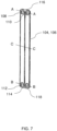
- Each of the first tubes and the second tubes comprises a pair of adjacent ducts including a first duct defined between the first tank and the third tank to allow flow of the fluid between the first tank and the third tank of the respective tube, and a second duct defined between the second tank and the fourth tank to allow flow of the fluid between the second tank and the fourth tank of the respective tube.
- Each of the first tubes comprises a pair of first plates coupled to each other.
- each of the first tubes comprises at least one inner fin arranged between the pair of first plates.
- Each of the second tubes comprises a first plate and a second plate coupled to each other.
- at least one inner fin is arranged between the first plate and the second plate.
- each of the first plates and the second plate comprises two connecting flanges extending from the respective plate at both opposite ends, and two adjacent duct-forming structures extending between the respective connecting flanges at the opposite ends.
- the second plate of each of the second tubes comprises a bypass groove between the connecting flanges at one end corresponding to the second end of the respective second tubes.
- the first plates can be flat compare to the second plates and the bypass grooves can be defined on the second plates.
- first tubes and the second tubes can be arranged alternatively in at least a portion of the heat exchanger core.
- the heat exchanger comprises a distribution device configured in the first passage of the heat exchanger core.
- the distribution device includes an inlet opening to receive the fluid and a plurality of spaced distribution openings configured along length of the distribution device to distribute the fluid in the first tanks.
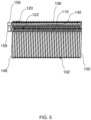
- the heat exchanger comprises a first end plate configured at a fluid inlet and exit side of the heat exchanger core and a second end plate configure at other side opposite to the fluid inlet and exit side of the heat exchanger core.
- Arrangement of the first tubes, the second tubes, and the end plates define two passes for the fluid through the heat exchanger.
- the heat exchanger further comprises a cap extended though the second end plate and adapted to block another opening, opposite to the inlet opening, of the distribution device.
- the heat exchanger comprises an inlet sleeve connected to the distribution device at the inlet side, and an outlet sleeve fluidically connected to the second passage through which the fluid egress the heat exchanger core.
- the present invention is explained in the forthcoming description and the accompanying drawings with an example of a heat exchanger for a HVAC system of a vehicle, more specifically, the present invention discloses an improved two-pass evaporator which can overcome drawbacks of the conventional two-pass evaporators.
- the proposed evaporator is provided with a first tubes and second tubes, wherein geometry/design of communication channels/bypass channels of the second tubes are modified to secure best refrigerant distribution/repartition across the evaporator with constrain to not degrade cooling power of the evaporator, thereby avoiding temperature non homogeneity on the evaporator surface.
- refrigerant bypass sections with restrictions are provided in the second tubes, and the second tubes are arranged in a fashion to insure efficient refrigerant distribution/repartition across the heat exchanger/evaporator.
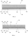
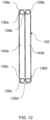
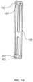
- the proposed invention discloses a heat exchanger 100, for instance an evaporator, for air conditioning system of a vehicle.
- the heat exchanger 100 includes a heat exchanger core 102 having a plurality of parallel tubes including first tubes 104 and second tubes 106, and a plurality of outer fins 105 arranged between adjacent tubes of the plurality of tubes 104 and 106.
- the plurality of tubes 104 and 106 are fluidically connected to each other by their both opposite ends.
- the heat exchanger 100 includes a pair of end plates including a first end plate 148 and a second end plate 150.
- the first end plate 148 is configured at a fluid inlet and exit side of the heat exchanger core 102
- the second end plate 150 is configure at other side opposite to the fluid inlet and exit side of the heat exchanger core 102.
- each of the first tubes 104 and the second tubes 106 includes a first tank 108 and a second tank 110 at a first end 116 of the respective tube 104/106.
- a third tank 112 and a fourth tank 114 are provided at a second end 118 of each of the first tubes 104 and the second tubes 106.
- the first tanks 108 of the plurality of tubes 104 and 106 are fluidically connected to each other and a first passage 120 is defined though the first tanks 108 to receive and distribute a fluid, such as but not limited to R-134a or R-1234yf refrigerant fluid but also to receive and distribute a natural refrigerant fluid such as carbon-dioxide(R744) or propane (R290), to the tubes 104 and 106.
- a fluid such as but not limited to R-134a or R-1234yf refrigerant fluid but also to receive and distribute a natural refrigerant fluid such as carbon-dioxide(R744) or propane (R290)
- R744 carbon-dioxide
- propane propane
- the third tanks 112 of the plurality of tubes 104 and 106 are fluidically connected to each other and a third passage 124 is defined though the third tanks 112.
- the fourth tanks 114 of the plurality of tubes 104 and 106 are fluidically connected to each other and a fourth passage 126 is defined though the fourth tanks 114.
- each of the first tubes 104 and the second tubes 106 comprises a pair of adjacent ducts including a first duct 130-1 and a second duct 130-2.
- the first duct 130-1 is defined between the first tank 108 and the third tank 112 to allow flow of the fluid between the first tank 108 and the third tank 112 of the respective tube 104/106
- the second duct 130-2 is defined between the second tank 110 and the fourth tank 114 to allow flow of the fluid between the second tank 110 and the fourth tank 114 of the respective tube 104/106.
- each of the tubes 104 and 106 allow flow of the fluid in two parallel ducts 130-1 and 130-2, in the first duct 130-1 the fluid can flow in a first flow direction (indicated by arrow 129) of the fluid and in the second duct 130-2 fluid can flow in a second flow direction (indicated by arrow 131) opposite to the first flow direction.
- each of the second tubes 106 comprises a bypass channel 128 between the respective third tank 112 and the fourth tank 114 to bypass at least a portion the fluid, flowing through the third passage 124 and/or received in the third tank 112, to the respective fourth tank 114 and/or the fourth passage 126 from respective the third tank 112 and/or the third passage, as shown in FIG. 6 .
- Cross-section of the bypass channel 128 of each of the second tubes 106 is in a range of 2.704 to 8.921 mm 2 .
- any cross-section of the bypass channel in the range of 2.704 to 8.921 mm 2 can be considered to enhance refrigerant fluid distribution/repartition across the heat exchanger 100 to improve temperature homogeneity on the heat exchanger surface, thereby increasing cooling power of the heat exchanger 100.
- cross-sections of the bypass channels 128 of the second tubes 106 can be different.
- the cross-sections of the bypass channels 128 of the second tubes 106 can be in a range of 6.542 to 7.021mm 2 .
- the cross-sections of the bypass channels 128 can be 6.742 mm2.
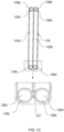
- the fluid or the refrigerant fluid When the fluid or the refrigerant fluid is distributed in the first tanks 108 of the plurality of tubes 104 and 106 though a distribution device 142 (as shown in FIG. 5 ) configured in the first passage 120 of the heat exchanger core 102, the fluid flows from the first tanks 108 or the first passage 120 to the third tanks 112 or the third passage 124 through the first ducts 130-1 of the first tube 104 and the second tubes 106.
- the fluid received in the third tanks 112 or the third passage 124 flow through the third passage 124 along a longitudinal axis of the heat exchanger 100 or from the fluid inlet and exit side of the core 102 to the side opposite to the fluid inlet and exit side of the core 102.
- the bypass channel 128 provided between the respective third tank 112 and the fourth tank 114 of the second tubes 106 bypass at least a portion the fluid, flowing through the third passage 124 and/or received in the third tank 112, to the respective fourth tank 114 and/or the fourth passage 126 to enable efficient distribution/repartition of the fluid/refrigerant fluid across the core 102 of the heat exchanger 100.
- This effective distribution/ repartition of the fluid/refrigerant fluid enhances cooling capacity of the heat exchanger 100 and reduce temperature non-homogeneity on the surface or the heat exchange surface of the heat exchanger 100.
- the heat exchange surface of the heat exchanger 100 is defined by outer surfaces of the plurality of tubes 104 and 106.
- outer spacers or fins 105 which are arranged between the adjacent tubes of the plurality of tubes 104 and 106 increase the surface area for heat exchange between the heat exchanger 100 and an external air flow passing through the heat exchanger 100.
- the fluid received in the fourth tanks 114 or the fourth passage 126 flows to the second tank 110 or the second passage 122 though the second ducts 130-2 of the first tube 104 and the second tubes 106 and further the fluid egress the heat exchanger 100 though an outlet sleeve 158 fluidically connected to the second passage 122.
- the outer fins 105 can have any suitable shape, such as but not limited to rectangular, corrugated, and the like.
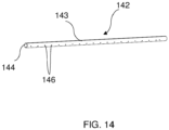
- the distribution device 142 can be flute shaped.
- the distribution device 142 includes a tubular member 143 having an inlet opening 144 to receive the fluid and a plurality of spaced distribution openings 146 configured along length of the tubular member 143 of the distribution device 142 to distribute the fluid in the first tanks 108 of the first tubes 104 and the second tube 106.
- the first tubes 104 and the second tubes 106 can be arranged alternatively in at least a portion of the core 102 proximal to the inlet exit side and in the remaining portion only second tubes 106 can be arranged.
- This alternate arrangement of the first tubes 104 and the second tubes 106 at least in a portion of the core 102 can slowdown flow of the refrigerant, which can improve refrigerant reparation/distribution along the longitudinal axis of the heat exchanger 100 and outer surface temperature homogeneity of the heat exchanger 100.
- the longitudinal axis of the heat exchanger 100 can be defined along an axis extending from the fluid inlet outlet side to other side opposite to the fluid inlet outlet side of the heat exchanger 100.
- the first tubes 104 and the second tubes 106 can be arranged alternatively in at least a portion of the core 102 proximal to the inlet exit side and further the second tubes 106 can be arranged, and then at least one first tube 104 can be arranged near the second end plate 150.
- This arrangement of the first tubes 104 and the second tubes 106 alternatively at least in a portion of the core 102 can slowdown flow of the refrigerant which improves the refrigerant distribution/repartition across the core 102, along with this arrangement of the first tube 104 near the second end plate 150 can improve mechanical resistance of the core 102.
- the arrangement of the first tubes 104, the second tubes 106 and the end plates 148 and 150 define two passes (as shown in FIG. 1 by dotted and solid lines) for the fluid through the heat exchanger 100.
- each of the first tubes 104 is made of a pair of first plates 132 coupled to each other.
- Each of the first plates are designed such that once the two first plates 132 are connected, define an internal fluid flow space between the two first plates 132.
- a material of the first plates 132 can be aluminum, aluminum alloy or any other suitable alloy.
- the pair of first plates 132 can be joined at the adjoining surfaces through a suitable joining process, such as brazing.
- at least one inner fin, such as an inner fin 133 is arranged between the pair of first plates 132.
- Each of the second tubes 106 is made of a first plate 132 and a second plate 134 that is coupled to the first plate 132.
- each of the first plate 132 and the second plate 134 are designed such that once the first plates 132 and the second plate 134 are connected, define an internal fluid flow space between the first plate 132 and the second plate 134.
- a material of the first plates 132 and the second plate 134 can be aluminum, aluminum alloy or any other suitable alloy.
- the first plates 132 and the second plate 134 can be joined at the adjoining surfaces through a suitable joining process, such as brazing.
- at least one inner fin such as an inner fin 133 is arranged between the first plates 132 and the second plate 134.
- the inner fins 133 can have any suitable shape, such as but not limited to corrugated shape, for creating turbulence in the flow of the fluid flowing through the respective tubes 104/106.
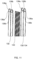
- each of the first plates 132 and the second plate 134 comprise two openings 136a and 136b at one end of plate corresponding to the first end of the respective tube 104/106, and two other openings 136c and 136d at another end of the plate corresponding to the second end of the respective tube 104/106.
- each of the first plates 132 and the second plate 134 includes connecting flanges 138a, 138b, 138c and 138d configured with the openings 136a, 136b, 136c and 136d at both opposite ends.
- the connecting flanges 138a, 138b, 138c and 138d are extended outwardly from the respective plate 132/134.
- each plate 132/134 is formed to connect one tube to adjacent tube to allow the refrigerant fluid to flow from one tube 104/106 to another adjacent tube 104/106 through the respective openings 136a, 136b, 136c and 136d.
- each of the connecting flanges 138a, 138b, 138c and 138d can be substantially bowl shaped without base.
- outer adjoining surfaces of the connecting flanges 138a, 138b, 138c and 138d of adjacent tubes 104/106 of the core 102 are brazed in a leak proof manner.
- each of the first plates 132 and the second plate 134 comprise two adjacent duct-forming structures 140a and 140b extending between the respective connecting flanges 138a, 138b, 138c, and 138d at the opposite ends.
- each of the duct-forming structures 140a and 140b can have a bottom and a raised peripheral edge extending from the bottom.
- the connecting flanges 138a, 138b, 138c and 138d are deeper than the duct-forming structures 140a and 140b.
- the first tank 108, the second tank 110, the third tank 112 and the fourth tank 114 of each of the first tubes 104 are defined by the connecting flanges 138a, 138b, 138c, and 138d of the pair of first plates 132 which are arranged with their concavities turned towards each other.
- the adjacent first and second ducts 130-1 and 130-2 of each of the first tubes 104 are defined through the duct forming structures 140a and 140b of the pair of first plates 132.
- first plates 132 can be mutually joined in fluid-tight manner at the abutting surfaces, such as but not limited to the edge regions and regions in between the duct forming structures 140a and 140b, by brazing to delimit the interior volume of the respective first tube 104.
- the first tank 108, the second tank 110, the third tank 112 and the fourth tank 114 of each of the second tubes 106 are defined by the connecting flanges 138a, 138b, 138c, and 138d of the first plate 132 and the second plate 134, which are arranged with their concavities turned towards each other.
- the adjacent first and second ducts 130-1 and130-2 of each of the second tubes 104 are defined through the duct forming structures 140a and 140b of the first plate 132 and the second plate 134.
- first plate 132 and the second plate 134 can be mutually joined in fluid-tight manner at the abutting surfaces, such as but not limited to, the edge regions and regions in between the duct forming structures 140a and 140b, by brazing to delimit the interior volume of the respective first tube 104.
- the second plate 134 of each of the second tubes 106 comprises a bypass groove 137 defined between the connecting flanges 138c and 138d at one end corresponding to the second end 118 of the respective second tubes 106.
- the bypass groove 137 is adapted to allow flow of the fluid between the adjacent flanges 138c and 138d.
- the bypass channel 128 between the third tank 112 and the fourth tank 114 of each of the second tubes 106 can be defined by the bypass groove 137 when the first plate 132 and the second plate 134 are joined together.
- the first plates 132 can be flat compare to the second plates 134 and the bypass grooves 137 can be defined on the second plates 134.
- the first end plate 148 is adapted to be fitted on the fluid inlet and outlet side of the heat exchanger 100, and includes a first hole 162 with a first collar 163 and a second hole 164 with a second collar 165 at one end of the first end plate 148.
- the first collar 163 and the second collar 165 are extended outwardly from the first end plate 148.
- An inlet sleeve 156 is fitted to the first collar 163 and fluidically connected to the distribution device 142 through the first hole 162 of the first end plate 148.
- the outlet sleeve 158 is fitted to the second collar 165 and flidically connected to the second passage 122 though the second hole of the first end plate 148.
- first end plate 148 includes a first protuberance 166 and a second protuberance 168 at the other end of the first end plate 148.
- the first protuberance 166 and the second protuberance 168 can be adapted to be received in respective openings 136c and 136d of the respective plate 132/134 arranged adjacent to the first end plate 148 to block the respective openings 136c and 136d and prevent further flow of the fluid.
- the second end plate 150 is adapted to be fitted other side, opposite to the fluid inlet and outlet side, of the heat exchanger 100.
- a cap 152 is extended though a hole 174 of the second end plate 150 and adapted to block another opening, opposite to the inlet opening 144, of the distribution device 142.
- the second end plate 150 includes a blind hole 167 to block further flow of the fluid flowing through the second passage 122 and return the fluid towards the inlet and exit side of the heat exchanger 100.
- the second end plate 150 includes a third protuberance 170 and a fourth protuberance 172 at the other end of the second end plate 150.
- the third protuberance 170 and the fourth protuberance 172 can be adapted to be received in respective openings 136c and 136d of the respective plate 132/134 arranged adjacent to the second end plate 150 to block the respective openings 136c and 136d to prevent further flow of the fluid.
Landscapes
- Engineering & Computer Science (AREA)
- Physics & Mathematics (AREA)
- Thermal Sciences (AREA)
- Mechanical Engineering (AREA)
- General Engineering & Computer Science (AREA)
- Heat-Exchange Devices With Radiators And Conduit Assemblies (AREA)
Priority Applications (1)
| Application Number | Priority Date | Filing Date | Title |
|---|---|---|---|
| EP23178291.3A EP4474745A1 (de) | 2023-06-08 | 2023-06-08 | Wärmetauscher für ein fahrzeug |
Applications Claiming Priority (1)
| Application Number | Priority Date | Filing Date | Title |
|---|---|---|---|
| EP23178291.3A EP4474745A1 (de) | 2023-06-08 | 2023-06-08 | Wärmetauscher für ein fahrzeug |
Publications (1)
| Publication Number | Publication Date |
|---|---|
| EP4474745A1 true EP4474745A1 (de) | 2024-12-11 |
Family
ID=86732422
Family Applications (1)
| Application Number | Title | Priority Date | Filing Date |
|---|---|---|---|
| EP23178291.3A Withdrawn EP4474745A1 (de) | 2023-06-08 | 2023-06-08 | Wärmetauscher für ein fahrzeug |
Country Status (1)
| Country | Link |
|---|---|
| EP (1) | EP4474745A1 (de) |
Citations (6)
| Publication number | Priority date | Publication date | Assignee | Title |
|---|---|---|---|---|
| JP2000018878A (ja) * | 1998-07-06 | 2000-01-18 | Showa Alum Corp | 積層型熱交換器 |
| US6321834B1 (en) * | 1999-10-01 | 2001-11-27 | Showa Denko K.K. | Laminate-type heat exchanger |
| US6920916B2 (en) * | 2000-12-28 | 2005-07-26 | Showa Denko K.K. | Layered heat exchangers |
| US7044205B2 (en) * | 2000-12-28 | 2006-05-16 | Showa Denko K.K. | Layered heat exchangers |
| US20070029075A1 (en) * | 2005-08-04 | 2007-02-08 | Mehendale Sunil S | Hybrid evaporator |
| FR2929387A1 (fr) * | 2008-03-25 | 2009-10-02 | Valeo Systemes Thermiques | Echangeur de chaleur a resistance a la pression amelioree |
-
2023
- 2023-06-08 EP EP23178291.3A patent/EP4474745A1/de not_active Withdrawn
Patent Citations (6)
| Publication number | Priority date | Publication date | Assignee | Title |
|---|---|---|---|---|
| JP2000018878A (ja) * | 1998-07-06 | 2000-01-18 | Showa Alum Corp | 積層型熱交換器 |
| US6321834B1 (en) * | 1999-10-01 | 2001-11-27 | Showa Denko K.K. | Laminate-type heat exchanger |
| US6920916B2 (en) * | 2000-12-28 | 2005-07-26 | Showa Denko K.K. | Layered heat exchangers |
| US7044205B2 (en) * | 2000-12-28 | 2006-05-16 | Showa Denko K.K. | Layered heat exchangers |
| US20070029075A1 (en) * | 2005-08-04 | 2007-02-08 | Mehendale Sunil S | Hybrid evaporator |
| FR2929387A1 (fr) * | 2008-03-25 | 2009-10-02 | Valeo Systemes Thermiques | Echangeur de chaleur a resistance a la pression amelioree |
Similar Documents
| Publication | Publication Date | Title |
|---|---|---|
| JP3391339B2 (ja) | 冷媒蒸発器 | |
| JP3988889B2 (ja) | 自動車用熱交換器 | |
| US6401804B1 (en) | Heat exchanger only using plural plates | |
| US20160138871A1 (en) | Duplex heat exchanger | |
| CN103889751B (zh) | 热交换器及使用该热交换器的热泵系统 | |
| JP6202451B2 (ja) | 熱交換器及び空気調和機 | |
| US9115934B2 (en) | Heat exchanger flow limiting baffle | |
| JP2000346568A (ja) | 熱交換器 | |
| JPH116693A (ja) | 車両空調用熱交換器 | |
| JP2010175241A (ja) | 2種類の流体のための熱交換器、特に空調装置のための蓄積蒸発器 | |
| CN102037307A (zh) | 用于热交换器的管 | |
| WO2007099868A1 (ja) | 熱交換器および一体型熱交換器 | |
| US7013952B2 (en) | Stack type heat exchanger | |
| US7051796B2 (en) | Heat exchanger | |
| JP2020100255A (ja) | 凝縮器、車両用空気調和装置 | |
| WO2008076274A1 (en) | Non-brazed insert for heat exchanger | |
| JP3677922B2 (ja) | 空調装置 | |
| JP2006329511A (ja) | 熱交換器 | |
| EP4474745A1 (de) | Wärmetauscher für ein fahrzeug | |
| JPH11153395A (ja) | 自動車用一体型熱交換器 | |
| JP6738233B2 (ja) | 蓄冷エバポレータ | |
| JP2001012821A (ja) | サーペンタイン型蒸発器 | |
| JP3702500B2 (ja) | 積層型熱交換器 | |
| JP6753666B2 (ja) | 蓄冷エバポレータ | |
| JP2004218852A (ja) | 熱交換器 |
Legal Events
| Date | Code | Title | Description |
|---|---|---|---|
| PUAI | Public reference made under article 153(3) epc to a published international application that has entered the european phase |
Free format text: ORIGINAL CODE: 0009012 |
|
| STAA | Information on the status of an ep patent application or granted ep patent |
Free format text: STATUS: THE APPLICATION HAS BEEN PUBLISHED |
|
| AK | Designated contracting states |
Kind code of ref document: A1 Designated state(s): AL AT BE BG CH CY CZ DE DK EE ES FI FR GB GR HR HU IE IS IT LI LT LU LV MC ME MK MT NL NO PL PT RO RS SE SI SK SM TR |
|
| STAA | Information on the status of an ep patent application or granted ep patent |
Free format text: STATUS: THE APPLICATION IS DEEMED TO BE WITHDRAWN |
|
| 18D | Application deemed to be withdrawn |
Effective date: 20250612 |