EP4474718A2 - Kombinationsgerät mit dunstabzugsvorrichtung und kochfeld - Google Patents
Kombinationsgerät mit dunstabzugsvorrichtung und kochfeld Download PDFInfo
- Publication number
- EP4474718A2 EP4474718A2 EP24201929.7A EP24201929A EP4474718A2 EP 4474718 A2 EP4474718 A2 EP 4474718A2 EP 24201929 A EP24201929 A EP 24201929A EP 4474718 A2 EP4474718 A2 EP 4474718A2
- Authority
- EP
- European Patent Office
- Prior art keywords
- filter
- hob
- combination
- fan
- unit
- Prior art date
- Legal status (The legal status is an assumption and is not a legal conclusion. Google has not performed a legal analysis and makes no representation as to the accuracy of the status listed.)
- Pending
Links
Images


Classifications
-
- F—MECHANICAL ENGINEERING; LIGHTING; HEATING; WEAPONS; BLASTING
- F24—HEATING; RANGES; VENTILATING
- F24C—DOMESTIC STOVES OR RANGES ; DETAILS OF DOMESTIC STOVES OR RANGES, OF GENERAL APPLICATION
- F24C15/00—Details
- F24C15/20—Removing cooking fumes
- F24C15/2042—Devices for removing cooking fumes structurally associated with a cooking range e.g. downdraft
-
- F—MECHANICAL ENGINEERING; LIGHTING; HEATING; WEAPONS; BLASTING
- F24—HEATING; RANGES; VENTILATING
- F24C—DOMESTIC STOVES OR RANGES ; DETAILS OF DOMESTIC STOVES OR RANGES, OF GENERAL APPLICATION
- F24C15/00—Details
- F24C15/20—Removing cooking fumes
- F24C15/2021—Arrangement or mounting of control or safety systems
-
- F—MECHANICAL ENGINEERING; LIGHTING; HEATING; WEAPONS; BLASTING
- F24—HEATING; RANGES; VENTILATING
- F24C—DOMESTIC STOVES OR RANGES ; DETAILS OF DOMESTIC STOVES OR RANGES, OF GENERAL APPLICATION
- F24C15/00—Details
- F24C15/20—Removing cooking fumes
- F24C15/2035—Arrangement or mounting of filters
Definitions
- the present invention relates to a combination appliance with extractor hood and hob.
- Cooking processes usually produce fumes and vapors. Extractor hoods are known which can be used to extract and clean the fumes and vapors. Combination devices are known for this purpose, for example, in which an extractor hood is arranged below the hob. Such a combination device is used, for example, in the DE 20 2013 005 303 U1 described.
- a housing for the heating or hob heating and control electronics is provided on the underside of the hob. Below the housing there is a fan housing for two or more radial fans, which suck air upwards from a cooking fume extraction chamber below.
- This embodiment has the disadvantage that the arrangement of the housing for the electronics reduces the space available underneath the hob, which is necessary for the fan and filters, for example.
- the object of the present invention is therefore to create a combination device which has a compact design and yet has a high efficiency in the extraction and filtering of fumes and vapors.
- a combination device which comprises a hob with at least one cooking module and an extractor device which is arranged at least partially beneath the at least one cooking module and which has a fan with at least one air inlet opening and a filter unit, and an extraction opening for the extractor device which is arranged in the hob.
- the combination device is characterized in that the fan is located beneath the intake opening, the filter unit is arranged at the extraction opening and the extractor device has a partition plate which separates the filter unit from the fan located underneath.
- directional information such as top and bottom as well as front and back refer to the combination appliance and its components in an installed state in which the hob and in particular the at least one cooking module are horizontal.
- the front is the side that faces the user.
- the back is the side that usually faces an installation wall.
- the back of the combination appliance is preferably the side through which purified air is emitted from the combination appliance.
- the dimension in the direction between the front and back is referred to as the depth.
- the horizontal dimension perpendicular to this is referred to as the width.
- the vertical dimension is referred to as the height.
- a combination appliance is a household appliance in which a hob and an extractor hood are combined.
- a combination appliance is a household appliance that can be installed in a kitchen as an assembly unit.
- the two components of the combination appliance i.e. the hob and the extractor hood, are supplied with power from a common power supply, for example a common power cable.
- the two components can be controlled by a common control device in which control devices for the two components are combined.
- the two components can also be operated by a common operating unit, which can also be referred to as a user interface.
- the combination device comprises a hob, an extractor device and an extraction opening for the extractor device.
- the hob has at least one cooking module.
- the hob preferably comprises a cover plate on which the cooking module or modules are arranged from below.
- the cover plate can be made of glass ceramic, for example.
- Each of the cooking modules forms at least one cooking zone, i.e. an area on which food can be heated on the hob.
- the cooking module can be an electrical heating module with a heating coil.
- the cooking module is preferably an induction module and is also referred to as an inductor.
- the induction module preferably comprises at least one induction coil.
- An induction module is understood to be a component that is intended to generate an alternating magnetic field by converting electrical energy.
- the combination appliance which serves to cause eddy currents and/or remagnetization effects in an at least partially ferromagnetic food container, for example a pot, which are converted into heat.
- an at least partially ferromagnetic food container for example a pot
- heat which are converted into heat.
- at least two cooking modules are provided. However, more, for example four or six cooking modules, can also be provided. A cooking zone is formed by each cooking module.
- the combination device also includes an extractor hood.
- An extractor hood is a device by means of which air, particularly contaminated air, for example in the form of fumes and vapors, can be sucked downwards from the space above the hob. The air is cleaned in the extractor hood and released as cleaned air or clean air from the extractor hood and the combination device.
- the extractor hood includes a fan for this purpose.
- the extractor device comprises a blower.
- a blower is understood here to be a unit consisting of a fan, in particular a fan wheel, and a blower housing surrounding the fan.
- the fan is preferably a radial fan, in particular a radial fan with forward-curved blades, and the blower housing is preferably a spiral housing, which can also be referred to as a worm housing.
- the extractor device is arranged at least partially underneath the at least one cooking module.
- at least the fan is arranged offset downwards relative to the cooking module(s).
- the fan has at least one air inlet opening.
- the fan also has an air outlet opening on the fan housing.
- the air inlet opening is made in the fan housing or is formed by it and represents the opening through which air can be sucked into the fan housing by the fan.
- the air inlet opening is perpendicular to the axis of rotation of the fan wheel.
- the fan is located under the suction opening.
- the fan is arranged under the suction opening in such a way that the air inlet opening of the fan facing the extraction opening.
- the axis of rotation of the fan wheel is preferably located in the middle of the extraction opening, i.e. in a vertical projection onto the extraction opening in the middle of the surface of the extraction opening.
- the combination device has an extraction opening for the extractor device.
- the extraction opening is the opening through which air enters the combination device from above the hob.
- the extraction opening for the extractor device is also referred to below as the extraction opening of the extractor device.
- the extraction opening is incorporated into the hob.
- the extraction opening is arranged in a recess in the hob, in particular a recess in the cover plate of the hob.
- the extraction opening can be located in the recess of the hob or be formed by it.
- the air inlet opening can be formed, for example, by the upper edge of a filter unit that is arranged in the recess.
- the cooking modules of the hob are arranged offset from the recess of the hob.
- the extraction opening preferably represents an elongated gap or slot that extends in the depth direction of the hob.
- the extraction opening is preferably arranged in the middle of the hob and in particular in the middle of the cover plate of the hob.
- the width of the extraction opening is less than or equal to the distance between laterally adjacent cooking modules of the hob.
- the length of the extraction opening in the depth direction can correspond to the depth of the hob.
- the extraction opening preferably ends at its rear end at a distance from the rear edge of the hob and at its front end at a distance from the front edge of the hob.
- the front end of the extraction opening is particularly preferably at a distance from a control element that is arranged in the front area of the hob and that is arranged in the middle of the width or, for example, extends across the width of the hob.
- the extractor device comprises a filter unit which comprises at least one grease filter.
- the grease filter can consist, for example, of expanded metal filter layers.
- the filter unit also comprises at least one odor filter.
- the filter unit is arranged at the suction opening.
- the filter unit is arranged below the suction opening and has a width which is greater than the width the extraction opening.
- the extractor device has a partition plate that separates the filter unit from the fan underneath.
- the partition plate is preferably part of the filter unit and in particular forms the base of the filter unit.
- the partition plate consists of an air-impermeable material.
- the partition plate preferably consists of a material that is also impermeable to liquids.
- the partition plate can be made of plastic.
- the partition plate is arranged in such a way that it separates the filter unit from the fan underneath.
- the partition plate covers the air inlet opening of the fan at the top. There is a vertical distance between the air inlet opening of the fan and the partition plate, which allows air to flow to the air inlet opening.
- a number of advantages can be achieved by arranging the fan below the extraction opening, arranging the filter unit at the extraction opening and providing a partition plate in the extractor device that separates the filter unit from the fan below it.
- the space under the hob can be used optimally.
- the space under the cooking modules is free for other components of the combination device.
- the flow path of the sucked-in fumes and vapors to the filters of the filter unit is small.
- the partition plate prevents liquids from entering the air inlet opening of the fan and also ensures targeted air flow in the extractor device.
- Liquids can enter if food is accidentally spilled on the hob, with the liquid dripping or running into the extraction opening.
- liquid separated on the filters of the filter unit can also drip down. By separating the blower from the filter unit using the separating plate, this liquid can be prevented from entering the air inlet of the blower.
- the separating plate has at least one recess.
- the recess can extend over the entire surface of the separating plate.
- the edge of the separating plate is formed, for example, by a raised strip of material.
- the recess only extends over part of the surface of the separating plate and is preferably provided in the middle of the separating plate.
- the recess in the separating plate allows a certain amount of liquid to be held or collected on the separating plate.
- the recess can therefore also be referred to as a collecting container or collecting channel.
- the recess in the separating plate is connected to a separate reservoir for holding a larger amount of liquid.
- the reservoir can be connected to an overflow of the recess.
- the partition plate is part of a housing for accommodating the filter unit.
- the partition plate can in particular form the base of the housing.
- At least one of the side walls of the housing, in particular the longitudinal walls of an elongated housing, are preferably formed by grids.
- the housing can have airtight walls on the front sides.
- the housing can be attached to the underside of the hob near the extraction opening.
- the housing can be attached in the extraction opening using a fastening element.
- the fastening element can extend downwards through the extraction opening and run outwards on the underside of the hob to the sides. This makes it possible to bridge the difference in width between the width of the extraction opening and the width of the housing, which is preferably larger.
- the partition plate is part of a housing, in particular the base of a housing, and at least one side wall of the housing is a grid
- the partition plate can prevent liquids from entering the blower and can also serve to hold at least one filter element of the filter unit.
- the at least one grid ensures the air flow to the air inlet opening of the blower and the grid can also serve as a system for at least one filter element.
- the grid and the partition plate prevent the user from reaching into the interior of the combination device and in particular the blower from above.
- At least one grease filter is arranged at an angle in the filter unit. This allows the filter surface of the grease filter to be increased at a low height and a targeted drainage of liquids along the grease filter can be ensured in comparison to a horizontally aligned grease filter.
- the grease filter particularly preferably has a V-shape, with the open side facing upwards.
- the grease filter can be made up of one or more parts.
- a filter element can be bent or folded in such a way that the V-shape is formed.
- the grease filter can consist of two filter elements, each of which forms a leg of the V-shape.
- the individual filter elements can be connected to one another directly or indirectly at the tip of the V-shape, or they can be separated from one another and can therefore be removed separately from the filter unit.
- the V-shaped grease filter is designed to be foldable. This can be achieved in a one-piece grease filter by choosing the filter material. Alternatively, for example, a weakening of the filter material can be introduced at the tip of the V-shape in a one-piece filter element, which allows the filter element to be folded and in particular folded up.
- the individual filter elements can be pivotally attached to one another. This attachment can be direct or indirect.
- the filter elements can be connected to one another via a joint or a connecting element to which each of the filter elements is pivotally attached. Because the grease filter is foldable, it can be removed from the extractor device and thus from the combination device through the suction opening after it has been folded up.
- the thickness of the grease filter is therefore preferably less than or equal to the width of the suction opening.
- the length of the grease filter is preferably less than or equal to the length of the suction opening.
- the underside of the grease filter is held in a collecting container.
- the collecting container can in particular be a rail or Hollow profile, for example a rectangular hollow profile with a gap in the top.
- the grease filter is connected to the collecting container, i.e. attached to it.
- the receiving container can also serve as a connecting element via which the two filter elements of the grease filter are hingedly connected.
- the width of the collecting container is therefore preferably less than or equal to the width of the extraction opening.
- the length of the collecting container is preferably less than or equal to the length of the extraction opening. If the collecting container is designed as a rail, an inward-facing web can be provided on each of the upper edges. This or a hollow profile with a gap in the top can prevent accidental escape or overflow of accumulated liquid in the collecting container when removing it from the extractor device.
- the collecting container is preferably made of a liquid-tight material, for example plastic or metal.
- the collecting container can be placed on the separating plate of the extractor device. If the separating plate has a recess, the collecting container can be placed on the recess or in the recess.
- the filter unit has at least one odor filter, which is arranged laterally adjacent to the at least one grease filter in the filter unit.
- the odor filter can have the form of a plate, mat or a molded body and can consist of activated carbon, for example, or have activated carbon or other odor-binding substances.
- the odor filter is preferably arranged so that it is located after the grease filter in the direction of flow.
- the odor filter is located at the same height in the extractor device as the grease filter. This reduces the space required in the vertical direction.
- the at least one odor filter is arranged in the direction of flow in front of the fan. This allows the odor filter to dampen the noise caused by the fan.
- the at least one odor filter is preferably held detachably in the filter unit. This means that the odor filter can be moved in the filter unit and can be removed from it.
- the odor filter can, for example, be placed on the separating plate of the extractor device. be placed on top and placed against a wall of the housing, which is formed by a grid. This holds the odor filter downwards and to one side in the housing. Since the odor filter is arranged laterally adjacent to the at least one grease filter, and the grease filter is preferably located in the area of the suction opening in a vertical projection of the suction opening, the odor filter is offset laterally outwards from the suction opening under a cooking module.
- the odor filter can be pulled towards the suction opening after the grease filter has been removed and removed via this.
- the thickness of the odor filter is therefore preferably less than or equal to the width of the suction opening and the length of the odor filter is preferably less than or equal to the length of the suction opening.
- the thickness of the odor filter is therefore preferably less than or equal to the width of the extraction opening, but the length of the odor filter is longer than the length of the extraction opening.
- the odor filter is designed in several parts, i.e. it consists of several filter elements. Each of the filter elements of the odor filter preferably has a length that is less than the length of the extraction opening.
- a central filter element of the odor filter can be removed and then a front and then a rear filter element of the odor filter can be moved into a position in which it can be brought under the extraction opening by pulling in the width direction of the extractor device to the extraction opening and can be removed via this.
- the odor filter can therefore consist, for example, of two, three or four filter elements that are not connected to one another.
- the combination device has at least one hob electronics unit and at least one extractor device electronics unit, and these electronics units are arranged to the side of the fan.
- the electronics units can have control and operating components as well as a power connection for the combination device.
- Power electronics are required to operate the hob and in particular the cooking module.
- the power electronics are used to supply the cooking module or modules with electrical energy.
- the power electronics can convert the electrical energy, for example in terms of the voltage form or the current.
- the power electronics can include, for example, filter components and control electronics.
- the elements of the power electronics are, for example, rectifiers for rectifying the alternating voltage of the household power network, inverters and switching devices, for example for power management. Power electronics are also required to operate the extractor device.
- operating electronics are required to operate the hob and the extractor device.
- a hob electronics unit and an extractor device electronics unit are arranged on each side of the centrally arranged fan.
- the electronics required for the extractor device can be divided into two electronic units, whereby, for example, the control electronics can be separated from the operating electronics.
- the electronic units can have supports on which the components are provided.
- the electronic units can each have an electronics housing in which the components, which may be attached to supports, are accommodated. Alternatively, the supports with the components can be separated from the air flow in the extractor hood by one or more internal walls in a device housing of the combination device.
- the hob electronics unit is preferably wider than the extractor hood electronics unit, and the hob electronics unit is arranged above the extractor hood electronics unit.
- This arrangement ensures that the hob electronics unit is close to the hob's cooking modules. It also optimises the air flow from the filter unit, which is arranged above the fan, to the fan's air inlet opening.
- the electronics units are preferably arranged above the fan. This arrangement enables the fan to have a size that corresponds to the size of the hob. The distance between the top of the fan and the hob can be used to accommodate the filter unit and the electronic units arranged offset to the side.
- the combination device therefore has a very compact design, but ensures optimum air flow from the extraction opening to the fan, particularly with the preferred arrangement of the electronic units, in which the electronics unit is provided with a smaller width than the lower electronics unit.
- the combination device has a device housing in which the components of the hob and the components of the extractor device are accommodated together.
- the fan, the filter unit, the extractor device electronics unit as well as the cooking modules of the hob and the hob electronics unit are accommodated in the device housing.
- the cover plate of the hob can also be accommodated in the device housing.
- the cover plate is accommodated in the device housing in such a way that it forms the top of the combination device and additionally encompasses the upper edge of the device housing.
- the cover plate can also be attached to the upper edge of the device housing or the device housing can be attached to the underside of the cover plate.
- the combination device has a common housing for the extractor device and the hob, the assembly of the combination device is simplified.
- the combination device can be mounted as one part in a worktop of a kitchen cabinet.
- the common device housing also simplifies the installation in that it is not necessary to align the components of the extractor hood with the components of the hob during installation.
- the invention thus creates a compact system that can still ensure adequate filtering.
- the present invention creates a combination device that can be low in height and does not lose storage space for the user, such as a drawer, at the bottom.
- the combination device can be designed in a width that is necessary for installation in standardized kitchens, for example the combination device can have a width of 60cm.
- Figure 1 is a schematic plan view of an embodiment of the combination appliance 1 according to the invention.
- the combination appliance 1 consists of a hob 10 and an extractor device 11, of which Figure 1 only the suction opening 111 is visible.
- the hob 10 consists of a cover plate 100 and cooking modules 101 arranged below the cover plate 100. In the embodiment shown, two cooking modules 101 are provided.
- a recess 1000 is made in the cover plate 100, which forms the air inlet opening 111.
- the recess 1000 is made in the middle of the width of the cover plate 100 and extends in the depth direction.
- the recess 1000 has a rectangular, elongated shape. The length of the recess 1000, i.e. its dimension in the depth direction, corresponds to the length of the cooking modules 101.
- the cooking modules 101 are arranged to the left and right of the recess 1000.
- the cooking modules 101 are located below the cover plate 100 and are preferably attached to the underside of the cover plate 100. Alternatively, the cooking modules 101 can also be held in a cooktop housing (not shown) and the cover plate 100 is attached to the cooktop housing in such a way that the cooking modules 101 are in the immediate vicinity or on the underside of the cover plate 100. If a hob housing is provided, this has a passage in the corresponding position of the recess 1000.
- a control unit 103 is arranged in the front area of the hob 10.
- the control unit 103 is arranged in front of the recess 1000 of the cover plate 100 and can include, for example, touch controls, buttons or rotary knobs.
- the control unit 103 can contain a display (not shown). Depending on the design of the individual elements of the control unit 103, it can be arranged on, inside and/or below the cover plate 100. At least the control electronics (not shown) of the control unit 103 are arranged below the cover plate 100.
- the combination device consists of the hob 10 and the extractor device 11.
- the combination device 1 has a device housing 12 in which the components of the extractor device 11 and the hob 10 are accommodated.
- Two cooking modules 101 of the hob 10 are shown, which rest against the cover plate 100 of the hob 10 from below and can also be referred to as induction modules.
- a fastening element 1140 is provided in the recess 1000. This has a removable grille in the recess 1000 and extends laterally beyond the recess 1000 on the underside of the cover plate 100.
- the opening of the fastening element 1140, which lies in the recess 1000, forms the suction opening 111 of the extractor device 11.
- a filter unit 114 is arranged below the recess 1000 and thus the suction opening 111.
- the filter unit 114 has a grease filter 1141 and two odor filters 115.
- the structure of the filter unit 114 will be described later with reference to the Figures 3 to 6 described in more detail.
- a housing 1142 for receiving the filter unit 114 is attached to the bottom of the fastening element 1140.
- the bottom of the housing 1142 represents a partition plate 1143.
- the fan 110 of the extractor device 11 is arranged on the bottom of the device housing 12 at a distance from the partition plate 1143.
- the fan 110 has a fan housing 1100 with an air inlet opening 1101 and an air outlet opening 1102 with a grille.
- the fan wheel 1103, which is driven by the motor 1104, is arranged in the blower housing 1100.
- the air inlet opening 1101 faces upwards and the axis of rotation of the fan wheel is vertical and below the air inlet opening 1101.
- the upper electronic unit 102 represents the hob electronic unit and the lower electronic unit represents the extractor device electronic unit 112.
- the width of the hob electronic unit 102 is greater than the width of the extractor device electronic unit 112.
- Both electronic units 102, 112 are arranged such that they rest against the device housing 12 on one side. There is therefore a step on the opposite side of the electronic units 102, 112.
- the suction opening 111 with the grease filter 1141 is shown schematically.
- the suction opening 111 of the extractor device is formed by the recess 1000 in the cover plate 100 of the hob 10 or between the cooking modules 101.
- the grease filter 1141 in this embodiment consists of two filter elements 11410, which are arranged at an angle to one another and form a V-shape.
- the underside of the filter elements 11410 are held in a collecting container 1144.
- the collecting container 1144 represents a rail that is open at the top.
- the suction opening 111 has a width D1 and the collecting container 1144 has a width C.
- the width C is less than or equal to the width D1.
- the filter elements 11410 are pivotally attached to the collecting container 1144.
- the grease filter 1141 can be folded together by folding the filter elements 11410. In the folded state, the grease filter 1141 can be removed upwards through the suction opening 111.
- FIG 4 A filter unit 114 with the filter element 114 and the two odor filters 115 is shown schematically.
- the grease filter 114 has the Figure 3
- the pivoting mounting of the filter elements 11410 on the collecting container 1144 is in Figure 4 indicated schematically by dots.
- the collecting container 1144 and the odor filters 115 are placed on the separating plate 1143.
- the odor filters 115 are arranged laterally adjacent to the grease filter 1141. In particular, on each side of the grease filter 1141, an odor filter 115 is moved to the side below the cover plate 100 to the recess 1000, which forms the suction opening 111.
- one of the odor filters 115 can be pushed on the separating plate 1143 in the direction of the suction opening 111 and removed upwards through it. This is shown in Figure 4 indicated by arrows.
- the thickness F of the odor filter 115 is less than the width of the recess 1000 and suction opening 111.
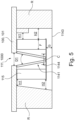
- FIG 5 The upper part of the combination device 1 is shown schematically.
- the space R which is used for the arrangement of Figure 5 not shown electronic units are indicated schematically.
- two variants of the possibility of installing electronic units are shown.
- On the left side a sloping partition wall is shown, to which electronic units can be installed to the left.
- On the right side the room is shown in such a way that a wider electronic unit can be installed in the upper area and a narrower electronic unit in the lower area.
- the distance between the odor filters 115 or the lateral ends of the partition plate 1143 is larger in the lower area (H2) than in the upper area (H1).
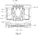
- the filter unit 114 of the combination device 1 is shown again in detail.
- the air flow through the filter unit 114 and to the air inlet opening 1101 is shown.
- the housing 1142 for the filter unit 114 is also shown.
- the separating plate 1143 has a recess 11430 in the middle.
- the separating plate 1143 in the embodiment shown forms the bottom of the housing 1142 for the filter unit 114.
- the side walls of the housing 1142 are each formed by a grid.
- the air passes through the V-shaped grease filter 1141.
- the air that has passed through a filter element 11410 reaches an odor filter 115 in the filter unit 114 and passes through it.
- the air is diverted downwards and flows between the partition plate 1143 and the top of the blower housing 1100 to the air inlet opening 1101 of the blower housing 1100. From there, the air is, as in Figure 2 shown, via the fan wheel 1103 to the air outlet opening 1102 and leaves the extractor device 11 and through an opening (not shown) in the device housing 12 also the combination device 1.
- the grease filter is designed to be as large as possible in order to increase filter efficiency and minimize flow resistance.
- the width of the extraction opening is limited by the left and right cooking modules.
- the length of the extraction opening is designed to be as long as possible, ideally as long as the depth of the cooking modules.
- the height of the combination device is limited. In particular, the device may only be so large that the storage space underneath, for example drawer space, is only used to a limited extent.
- the grease filter preferably has a V-shape, whereby the filter is foldable.
- a sealed container which can also be called a collecting container, is connected to the filter.
- the width of the collecting container is less than the width of the extraction opening, in particular the recess in the hob.
- the odor filters are preferably mounted outside the folding grease filter to the left and right of it.
- the thickness of the odor filters F is less than the width of the extraction opening D1 in the hob.
- the length of the odor filter can correspond to the depth of the extraction opening and is preferably less than the length of the odor filter. However, it is also within the scope of the invention for the odor filter to have a greater length than the depth of the extraction opening.
- the odor filter can be made up of several parts, whereby the individual parts can be removed separately through the extraction opening. The individual parts each have a length that is less than the depth of the extraction opening.
- the hob electronics especially the circuit boards, are usually arranged under the hobs, in order to gain space, the invention has the electronics preferably placed outside the air flow.
- the distance H does not necessarily have to be the same over the entire height of the filter. It can be designed so that H1 ⁇ H2.
- a separating plate ensures that the air flows through the grease filter and odor filter and into the blower, which can also be referred to as a fan.
- a preferred distance G>20mm ensures that enough air reaches the fan wheel.
- the separating plate is preferably constructed in such a way that it forms a pan. In the case that liquid flows in, the pan is preferably connected to a separate reservoir. Walls under the pan serve to prevent liquid from falling into the air inlet opening through capillarity and thus into the fan wheel and the motor.
- a grid in the flow direction after the odor filter preferably serves as a stop for the filter and ensures that the user cannot intervene in the motor.
- no separate ventilation system is installed under the cooking plate, but rather a complete combination device with both functions (cooking and ventilation) is provided.
- a complete combination device with both functions cooking and ventilation
Landscapes
- Engineering & Computer Science (AREA)
- Chemical & Material Sciences (AREA)
- Combustion & Propulsion (AREA)
- Mechanical Engineering (AREA)
- General Engineering & Computer Science (AREA)
- Ventilation (AREA)
- Filtering Of Dispersed Particles In Gases (AREA)
Abstract
Description
- Die vorliegende Erfindung betrifft ein Kombinationsgerät mit Dunstabzugsvorrichtung und Kochfeld.
- Bei Kochvorgängen entstehen in der Regel Dünste und Wrasen. Es sind Dunstabzugsvorrichtungen bekannt, mittels derer die Dünste und Wrasen abgesaugt und gereinigt werden können. Hierzu sind beispielsweise Kombinationsgeräte bekannt, bei denen eine Dunstabzugsvorrichtung unterhalb des Kochfeldes angeordnet ist. Ein solches Kombinationsgerät ist beispielsweise in der
DE 20 2013 005 303 U1 beschrieben. Bei diesem Kombinationsgerät ist an der Unterseite des Kochfeldes ein Gehäuse für die Beheizungs- oder Kochfeldbeheizung- und Steuerelektronik vorgesehen. Unterhalb des Gehäuses ist ein Lüfter-Gehäuse für zwei oder mehr Radiallüfter angeordnet, die Luft aus einer darunterliegenden Kochdunstansaugkammer nach oben ansaugen. - Diese Ausführungsform weist den Nachteil auf, dass durch die Anordnung des Gehäuses für die Elektronik der Bauraum, der unterhalb des Kochfeldes zur Verfügung steht und der beispielsweise für das Gebläse und für Filter notwendig ist, reduziert ist.
- Aufgabe der vorliegenden Erfindung ist es daher ein Kombinationsgerät zu schaffen, das einen kompakten Aufbau aufweist und dennoch eine hohe Effizienz bei der Absaugung und Filterung der Dünste und Wrasen aufweist.
- Die Aufgabe wird daher gelöst durch ein Kombinationsgerät, das ein Kochfeld mit mindestens einem Kochmodul und eine Dunstabzugsvorrichtung, die zumindest teilweise unterhalb des mindestens einen Kochmoduls angeordnet ist und die ein Gebläse mit mindestens einer Lufteinlassöffnung und eine Filtereinheit aufweist, und eine Absaugöffnung für die Dunstabzugsvorrichtung umfasst, die in dem Kochfeld angeordnet ist. Das Kombinationsgerät ist, dadurch gekennzeichnet, dass das Gebläse unterhalb der Ansaugöffnung liegt, die Filtereinheit an der Absaugöffnung angeordnet ist und die Dunstabzugsvorrichtung eine Trennplatte aufweist, die die Filtereinheit von dem darunter liegenden Gebläse trennt.
- Richtungsangaben, wie beispielsweise oben und unten sowie vorne und hinten beziehen sich soweit nicht anders angegeben auf das Kombinationsgerät und dessen Bestandteile in einem eingebauten Zustand, bei dem das Kochfeld und insbesondere das mindestens eine Kochmodul in der Horizontalen liegen. Als Vorderseite wird die Seite bezeichnet, die dem Benutzer zugewandt ist. Die Rückseite ist die Seite, die in der Regel einer Montagewand zugewandt ist. Zudem ist die Rückseite des Kombinationsgerätes vorzugsweise die Seite, über die gereinigte Luft aus dem Kombinationsgerät ausgegeben wird. Die Abmessung in der Richtung zwischen Vorderseite und Rückseite wird als Tiefe bezeichnet. Die dazu senkrechte Abmessung in der Horizontalen wird als Breite bezeichnet. Die Abmessung in der Vertikalen wird als Höhe bezeichnet.
- Als Kombinationsgerät wird ein Haushaltsgerät bezeichnet, bei dem ein Kochfeld und eine Dunstabzugsvorrichtung miteinander kombiniert sind. Insbesondere wird als Kombinationsgerät ein Haushaltsgerät bezeichnet, das als eine Montageeinheit in eine Küche eingebaut werden kann. Vorzugsweise werden die beiden Komponenten des Kombinationsgerätes, das heißt das Kochfeld und die Dunstabzugsvorrichtung durch eine gemeinsame Stromversorgung beispielsweise ein gemeinsames Netzkabel versorgt. Zudem kann die Steuerung der beiden Komponenten durch eine gemeinsame Steuervorrichtung erfolgen, bei der Steuervorrichtungen für die beiden Komponenten kombiniert sind. Beispielsweise können die beiden Komponenten auch durch eine gemeinsame Bedieneinheit, die auch als User-Interface bezeichnet werden kann, bedient werden.
- Das Kombinationsgerät umfasst ein Kochfeld, eine Dunstabzugsvorrichtung sowie eine Absaugöffnung für die Dunstabzugsvorrichtung. Das Kochfeld weist mindestens ein Kochmodul auf. Zudem umfasst das Kochfeld vorzugsweise eine Deckplatte an der das oder die Kochmodule von unten angeordnet sind. Die Deckplatte kann beispielsweise aus Glaskeramik bestehen. Durch jedes der Kochmodule wird mindestens eine Kochzone gebildet, das heißt ein Bereich auf dem auf dem Kochfeld Gargut erwärmt werden kann. Das Kochmodul kann ein elektrisches Heizmodul mit einer Heizspule darstellen. Das Kochmodul stellt aber vorzugsweise ein Induktionsmodul dar und wird auch als Induktor bezeichnet. Das Induktionsmodul umfasst vorzugsweise zumindest eine Induktionsspule. Als Induktionsmodul wird insbesondere ein Bauteil verstanden, das dazu vorgesehen ist, unter Umwandlung von elektrischer Energie ein magnetisches Wechselfeld zu erzeugen, das dazu dient in einem zumindest teilweise ferromagnetischen Gargutbehälter, beispielsweise einem Topf, Wirbelströme und/oder Ummagnetisierungseffekte hervorzurufen, die in Wärme umgewandelt werden. In dem Kochfeld des erfindungsgemäßen Kombinationsgerätes sind vorzugsweise mindestens zwei Kochmodule vorgesehen. Es können aber auch mehr, beispielsweise vier oder sechs Kochmodule vorgesehen sein. Durch jedes Kochmodul wird eine Kochzone gebildet.
- Das Kombinationsgerät umfasst weiterhin eine Dunstabzugsvorrichtung. Als Dunstabzugsvorrichtung wird eine Vorrichtung bezeichnet, mittels derer Luft, insbesondere verunreinigte Luft, beispielsweise in Form von Dünsten und Wrasen von dem Raum oberhalb des Kochfeldes nach unten abgesaugt werden kann. In der Dunstabzugsvorrichtung wird die Luft gereinigt und als gereinigte Luft beziehungsweise Reinluft aus der Dunstabzugsvorrichtung und dem Kombinationsgerät abgegeben. Die Dunstabzugsvorrichtung umfasst hierzu ein Gebläse.
- Die Dunstabzugsvorrichtung umfasst ein Gebläse. Als Gebläse wird hierbei eine Einheit bestehend aus einem Lüfter, insbesondere Lüfterrad, und einem den Lüfter umgebenden Gebläsegehäuse verstanden. Der Lüfter stellt vorzugsweise einen Radiallüfter, insbesondere einen Radiallüfter mit vorwärts gekrümmten Schaufeln, dar und das Gebläsegehäuse stellt vorzugsweise ein Spiralgehäuse dar, das auch als Schneckengehäuse bezeichnet werden kann.
- Die Dunstabzugsvorrichtung ist zumindest teilweise unterhalb des mindestens einen Kochmoduls angeordnet. Insbesondere ist zumindest das Gebläse zu dem oder den Kochmodulen nach unten versetzt angeordnet.
- Das Gebläse weist zumindest eine Lufteinlassöffnung auf. Zudem weist das Gebläse eine Luftauslassöffnung an dem Gebläsegehäuse auf. Die Lufteinlassöffnung ist in dem Gebläsegehäuse eingebracht, beziehungsweise durch diese gebildet, und stellt die Öffnung dar, über die Luft durch den Lüfter in das Gebläsegehäuse eingesaugt werden kann. Die Lufteinlassöffnung steht dabei senkrecht zu der Drehachse des Lüfterrades.
- Das Gebläse liegt erfindungsgemäß unter der Absaugöffnung. Insbesondere ist das Gebläse so unter der Absaugöffnung angeordnet, dass die Lufteinlassöffnung des Gebläses der Absaugöffnung zugewandt ist. Die Drehachse des Lüfterrades liegt dabei vorzugsweise in der Mitte der Absaugöffnung, das heißt in senkrechter Projektion auf die Absaugöffnung in der Mitte der Fläche der Absaugöffnung.
- Das Kombinationsgerät weist eine Absaugöffnung für die Dunstabzugsvorrichtung auf. Als Absaugöffnung wird die Öffnung bezeichnet, über die Luft von oberhalb des Kochfeldes in das Kombinationsgerät eintritt. Die Absaugöffnung für die Dunstabzugsvorrichtung wird im Folgenden auch als Absaugöffnung der Dunstabzugsvorrichtung bezeichnet. Die Absaugöffnung ist in das Kochfeld eingebracht. Insbesondere ist die Absaugöffnung in einer Aussparung in dem Kochfeld, insbesondere einer Aussparung in der Deckplatte des Kochfeldes angeordnet. Die Absaugöffnung kann in der Aussparung des Kochfeldes liegen oder durch diese gebildet sein. Im ersten Fall kann die Lufteinlassöffnung beispielsweise durch den oberen Rand einer Filtereinheit gebildet sein, die in der Aussparung angeordnet ist. Die Kochmodule des Kochfeldes sind zu der Aussparung des Kochfeldes versetzt angeordnet.
- Die Absaugöffnung stellt vorzugsweise einen länglichen Spalt oder Schlitz dar, der sich in Tiefenrichtung des Kochfeldes erstreckt. Vorzugsweise ist die Absaugöffnung in der Mitte des Kochfeldes und insbesondere in der Mitte der Deckplatte des Kochfeldes angeordnet. Die Breite der Absaugöffnung ist kleiner oder gleich dem Abstand von seitlich benachbarten Kochmodulen des Kochfeldes. Die Länge der Absaugöffnung in Tiefenrichtung kann der Tiefe des Kochfeldes entsprechen. Vorzugsweise endet die Absaugöffnung aber an deren hinteren Ende in einem Abstand zur rückwärtigen Kante des Kochfeldes und an deren vorderen Ende in einem Abstand zu der vorderen Kante des Kochfeldes. Besonders bevorzugt liegt das vordere Ende der Absaugöffnung in einem Abstand zu einem Bedienteil, das im vorderen Bereich des Kochfeldes angeordnet ist und das in der Mitte der Breite angeordnet ist oder sich beispielsweise über die Breite des Kochfeldes erstreckt.
- Die Dunstabzugsvorrichtung umfasst eine Filtereinheit, die mindestens einen Fettfilter umfasst. Der Fettfilter kann beispielsweise aus Streckmetallfilterlagen bestehen. Besonders bevorzugt umfasst die Filtereinheit zudem mindestens einen Geruchsfilter. Die Filtereinheit ist an der Absaugöffnung angeordnet. Insbesondere ist die Filtereinheit unterhalb der Absaugöffnung angeordnet und weist eine Breite auf, die größer ist als die Breite der Absaugöffnung. Durch eine solche Bereit der Filtereinheit kann das oder können die Filterelemente, insbesondere Fettfilter und Geruchsfilter so angeordnet werden, dass diese die Absaugöffnung an deren oberen Ende nicht versperren. Dadurch wird der Eintritt von Luft in die Absaugöffnung und damit in die Filtereinheit gewährleistet.
- Die Dunstabzugsvorrichtung weist erfindungsgemäß eine Trennplatte auf, die die Filtereinheit von dem darunter liegenden Gebläse trennt. Die Trennplatte ist vorzugsweise Teil der Filtereinheit und bildet insbesondere den Boden der Filtereinheit. Die Trennplatte besteht aus einem luftundurchlässigen Material. Vorzugsweise besteht die Trennplatte aus einem Material, das auch flüssigkeitsundurchlässig ist. Beispielsweise kann die Trennplatte aus Plastik bestehen. Die Trennplatte ist so angeordnet, dass diese die Filtereinheit von dem darunter liegenden Gebläse trennt. Insbesondere deckt die Trennplatte die Lufteinlassöffnung des Gebläses nach oben ab. Hierbei ist zwischen der Lufteinlassöffnung des Gebläses und der Trennplatte ein vertikaler Abstand gegeben, der einen Luftstrom zu der Lufteinlassöffnung erlaubt.
- Indem das Gebläse unterhalb der Absaugöffnung angeordnet ist, die Filtereinheit an der Absaugöffnung angeordnet ist und eine Trennplatte in der Dunstabzugsvorrichtung vorgesehen ist, die die Filtereinheit von dem darunterliegenden Gebläse trennt, kann eine Reihe von Vorteilen erzielt werden. Insbesondere kann durch die Anordnung des Gebläses unterhalb der Absaugöffnung und der Anordnung der Filtereinheit an der Absaugöffnung der Raum unter dem Kochfeld optimal genutzt werden. Insbesondere ist der Raum unterhalb der Kochmodule für weitere Komponenten des Kombinationsgerätes frei. Zudem ist der Strömungsweg der eingesaugten Dünste und Wrasen zu den Filtern der Filtereinheit gering. Schließlich wird durch die Trennplatte zum einen ein Eintreten von Flüssigkeiten in die Lufteinlassöffnung des Gebläses verhindert und zum anderen wird eine gezielte Luftführung in der Dunstabzugsvorrichtung gewährleistet. Das Eintreten von Flüssigkeiten kann durch versehentliches Verschütten von Gargut auf dem Kochfeld auftreten, wobei die Flüssigkeit in die Absaugöffnung tropft oder läuft. Zudem kann auch an den Filtern der Filtereinheit abgeschiedene Flüssigkeit nach unten tropfen. Indem das Gebläse durch die Trennplatte von der Filtereinheit getrennt ist, kann das Eintreten dieser Flüssigkeit in die Lufteinlassöffnung des Gebläses verhindert werden.
- Gemäß einer Ausführungsform weist die Trennplatte mindestens eine Vertiefung auf. Die Vertiefung kann sich über die gesamte Fläche der Trennplatte erstrecken. In diesem Fall wird der Rand der Trennplatte beispielsweise durch einen hochstehenden Materialstreifen gebildet. Alternativ erstreckt sich die Vertiefung nur über einen Teil der Fläche der Trennplatte und ist vorzugsweise in der Mitte der Trennplatte vorgesehen. Durch die Vertiefung in der Trennplatte kann eine gewisse Menge an Flüssigkeit auf der Trennplatte gehalten oder gesammelt werden. Die Vertiefung kann daher auch als Sammelbehälter oder Sammelrinne bezeichnet werden. Vorzugsweise ist die Vertiefung der Trennplatte mit einem separaten Reservoir zur Aufnahme einer größeren Menge an Flüssigkeit verbunden. Insbesondere kann das Reservoir mit einem Überlauf der Vertiefung verbunden sein.
- Gemäß einer Ausführungsform stellt die Trennplatte Teil eines Gehäuses zur Aufnahme der Filtereinheit dar. Die Trennplatte kann insbesondere den Boden des Gehäuses bilden. Mindestens eine der Seitenwände des Gehäuses, insbesondere die Längswände eines länglichen Gehäuses, werden hierbei vorzugsweise durch Gitter gebildet. An den Stirnseiten kann das Gehäuse luftundurchlässige Wände aufweisen. Das Gehäuse kann an der Unterseite des Kochfeldes in der Nähe der Absaugöffnung befestigt sein. Alternativ kann das Gehäuse über ein Befestigungselement in der Absaugöffnung befestigt werden. Hierzu kann sich das Befestigungselement durch die Absaugöffnung nach unten erstrecken und an der Unterseite des Kochfeldes zu den Seiten nach außen verlaufen. Hierdurch kann der Breitenunterschied zwischen der Breite der Absaugöffnung und der Breite des Gehäuses, die vorzugsweise größer ist, überbrückt werden.
- Indem die Trennplatte Teil eines Gehäuses, insbesondere der Boden eines Gehäuses ist und zumindest eine Seitenwand des Gehäuses ein Gitter darstellt, kann durch die Trennplatte zum einen das Eintreten von Flüssigkeiten in das Gebläse verhindert werden und zum anderen kann die Trennplatte zum Halten zumindest eines Filterelementes der Filtereinheit dienen. Zudem wird durch das mindestens eine Gitter der Luftstrom zu der Lufteinassöffnung des Gebläses gewährleistet und zum anderen kann das Gitter als Anlage für mindestens ein Filterelement dienen. Schließlich wird durch das Gitter und die Trennplatte der Eingriff des Benutzers von oben in das Innere des Kombinationsgerätes und insbesondere das Gebläse verhindert.
- Gemäß einer Ausführungsform ist mindestens ein Fettfilter in der Filtereinheit geneigt angeordnet. Hierdurch kann auf einer geringen Höhe die Filterfläche des Fettfilters vergrößert werden und ein gezieltes Ablaufen von Flüssigkeiten entlang dem Fettfilter kann im Vergleich zu einem horizontal ausgerichteten Fettfilter, sichergestellt werden.
- Besonders bevorzugt weist der Fettfilter eine V-Form auf, deren offene Seite nach oben gerichtet ist. Der Fettfilter kann hierbei einteilig oder mehrteilig ausgebildet sein. Insbesondere kann ein Filterelement so gebogen oder gefaltet sein, dass die V-Form gebildet wird. Alternativ kann der Fettfilter aus zwei Filterelementen bestehen, von denen jeweils eines einen Schenkel der V-Form bildet. Die einzelnen Filterelemente können miteinander an der Spitze der V-Form mittelbar oder unmittelbar verbunden sein oder können voneinander getrennt sein und damit getrennt aus der Filtereinheit entnehmbar sein. Indem der Fettfilter eine V-Form aufweist, kann die Filterfläche bei geringer Höhe maximiert werden. Zudem ist der Anströmwinkel, unter dem die über die Absaugöffnung angesaugte Luft den Fettfilter anströmt verbessert. Insbesondere kann ein paralleles Anströmen, das bei vertikal ausgerichteten Fettfiltern auftreten würde, verhindert werden.
- Gemäß einer bevorzugten Ausführungsform ist der V-förmige Fettfilter klappbar ausgestaltet. Dies kann bei einem einteiligen Fettfilter durch die Wahl des Filtermaterials erreicht werden. Alternativ kann beispielsweise an der Spitze der V-Form bei einem einteiligen Filterelement eine Schwächung des Filtermaterials eingebracht sein, die das Klappen und insbesondere das Zusammenklappen des Filterelementes erlaubt. Bei einem zweiteiligen Fettfilter können die einzelnen Filterelemente schwenkbar aneinander befestigt sein. Diese Befestigung kann unmittelbar oder mittelbar sein. Insbesondere können die Filterelemente über ein Gelenk oder über ein Verbindungselement miteinander verbunden sein, an dem jedes der Filterelemente schwenkbar befestigt ist. Indem der Fettfilter klappbar ist, kann dieser nach dem Zusammenklappen durch die Absaugöffnung nach oben aus der Dunstabzugsvorrichtung und damit dem Kombinationsgerät entnommen werden. Die Dicke des Fettfilters ist daher vorzugsweise kleiner oder gleich der Breite der Absaugöffnung. Die Länge des Fettfilters ist vorzugsweise kleiner oder gleich der Länge der Absaugöffnung.
- Gemäß einer Ausführungsform ist die Unterseite des Fettfilters in einem Auffangbehälter gehalten. Der Auffangbehälter kann insbesondere eine nach oben offene Schiene oder Hohlprofil, beispielsweise rechteckiges Hohlprofil mit einem in der Oberseite vorgesehenen Spalt sein. Der Fettfilter ist mit dem Auffangbehälter verbunden, das heißt daran befestigt. Indem ein Auffangbehälter vorgesehen ist, der den Fettfilter an der Unterseite hält und mit diesem verbunden ist, kann zum einen Flüssigkeit, die von dem Fettfilter abtropft oder an diesem herunter läuft aufgefangen werden. Zum anderen kann der Fettfilter zusammen mit dem Aufnahmebehälter aus der Dunstabzugsvorrichtung entnommen und gereinigt werden. Schließlich kann der Aufnahmebehälter bei einem zweiteiligen Fettfilter auch als Verbindungselement dienen, über das die beiden Filterelemente des Fettfilters klappbar verbunden sind. Die Breite des Auffangbehälters ist daher vorzugsweise kleiner oder gleich der Breite der Absaugöffnung. Die Länge des Auffangbehälters ist vorzugsweise kleiner oder gleich der Länge der Absaugöffnung. Bei der Ausführungsform des Auffangbehälters als Schiene kann an den oberen Kanten jeweils ein nach innen gerichteter Steg vorgesehen sein. Hierdurch oder bei einem Hohlprofil mit Spalt in der Oberseite kann ein versehentliches Entweichen oder Überlaufen von angesammelter Flüssigkeit in dem Auffangbehälter bei der Entnahme aus der Dunstabzugsvorrichtung verhindert werden. Der Auffangbehälter besteht vorzugsweise aus einem flüssigkeitsdichten Material, beispielsweise aus Kunststoff oder Metall. Der Auffangbehälter kann auf die Trennplatte der Dunstabzugsvorrichtung aufgesetzt werden. Bei einer Trennplatte, die eine Vertiefung aufweist, kann der Auffangbehälter auf die Vertiefung oder in die Vertiefung gesetzt werden.
- Gemäß einer Ausführungsform weist die Filtereinheit zumindest einen Geruchsfilter auf, der zu dem mindestens einen Fettfilter seitlich benachbart in der Filtereinheit angeordnet ist. Der Geruchsfilter kann die Form einer Platte, Matte oder eines Formkörpers haben und beispielsweise aus Aktivkohle bestehen oder Aktivkohle oder andere geruchsbindende Stoffe aufweisen. Vorzugsweise ist der Geruchsfilter so angeordnet, dass dieser in Strömungsrichtung nach dem Fettfilter liegt. Der Geruchsfilter liegt dabei in der gleichen Höhe in der Dunstabzugsvorrichtung, wie der Fettfilter. Hierdurch ist der Platzbedarf in vertikaler Richtung verringert. Zudem ist bei dieser Anordnung der mindestens eine Geruchsfilter in Strömungsrichtung vor dem Gebläse angeordnet. Hierdurch kann der Geruchsfilter die von dem Gebläse verursachten Geräusche dämmen. Der mindestens eine Geruchsfilter ist vorzugsweise lösbar in der Filtereinheit gehalten. Dies bedeutet, dass der Geruchsfilter in der Filtereinheit bewegt werden kann und aus dieser entnommen werden kann. Der Geruchsfilter kann beispielsweise auf die Trennplatte der Dunstabzugsvorrichtung aufgesetzt sein und an einer Wand des Gehäuses, das durch ein Gitter gebildet wird, angelegt sein. Hierdurch ist der Geruchsfilter nach unten und zu einer Seite in dem Gehäuse gehalten. Da der Geruchsfilter zu dem mindestens einen Fettfilter seitlich benachbart angeordnet ist, und der Fettfilter vorzugsweise in senkrechter Projektion der Absaugöffnung in der Fläche der Absaugöffnung liegt, liegt der Geruchsfilter zu der Absaugöffnung seitlich nach außen versetzt unter einem Kochmodul. Aus dieser Position kann der Geruchsfilter nach der Entnahme des Fettfilters in Richtung der Absaugöffnung gezogen und über diese entnommen werden. Die Dicke des Geruchfilters ist daher vorzugsweise kleiner oder gleich der Breite der Absaugöffnung und die Länge des Geruchsfilters ist vorzugsweise kleiner oder gleich der Länge der Absaugöffnung.
- Gemäß einer alternativen Ausführungsform ist die Dicke des Geruchfilters ist daher vorzugsweise kleiner oder gleich der Breite der Absaugöffnung aber die Länge des Geruchsfilters länger als die Länge der Absaugöffnung. Bei dieser Ausführungsform ist der Geruchsfilter mehrteilig ausgebildet, das heißt besteht aus mehreren Filterelementen. Jedes der Filterelemente des Geruchsfilters weist dabei vorzugsweise eine Länge auf, die geringer ist, als die Länge der Absaugöffnung. Bei dieser Ausführungsform kann beispielsweise ein mittiges Filterelement des Geruchsfilters entnommen werden und anschließend ein vorderes und danach ein hinteres Filterelement des Geruchsfilters durch Verschieben in eine Position gebracht werden, in der dieses durch Ziehen in Breitenrichtung der Dunstabzugsvorrichtung zu der Absaugöffnung unter die Absaugöffnung gebracht und über diese entnommen werden kann. Der Geruchsfilter kann daher beispielsweise aus zwei, drei oder vier Filterelementen bestehen, die nicht miteinander verbunden sind.
- Gemäß einer Ausführungsform weist das Kombinationsgerät mindestens eine Kochfeldelektronikeinheit und mindestens eine Dunstabzugsvorrichtungselektronikeinheit auf und diese Elektronikeinheiten sind seitlich zu dem Gebläse angeordnet. Die Elektronikeinheiten können Steuerungs- und Bedienkomponenten sowie einen Netzanschluss für das Kombinationsgerät aufweisen. Zum Betreiben des Kochfeldes und insbesondere des Kochmoduls ist eine Leistungselektronik erforderlich. Die Leistungselektronik wird dazu verwendet, das oder die Kochmodule mit elektrischer Energie zu versorgen. Hierbei kann die Leistungselektronik die elektrische Energie beispielsweise bezüglich der Spannungsform oder des Stroms umformen. Die Leistungselektronik kann dabei beispielsweise Filterbauteile und Steuerungselektronik umfassen. Die Elemente der Leistungselektronik sind beispielsweise Gleichrichter zum Gleichrichten der Wechselspannung des Haushaltsstromnetzes, Wechselrichter und Schaltvorrichtungen, beispielsweise zum Leistungsmanagement. Auch zum Betreiben der Dunstabzugsvorrichtung ist eine Leistungselektronik erforderlich. Zudem ist eine Bedienelektronik erforderlich, um das Kochfeld und die Dunstabzugsvorrichtung zu bedienen. Besonders bevorzugt ist auf jeder Seite des mittig angeordneten Gebläses jeweils eine Kochfeldelektronikeinheit und eine Dunstabzugsvorrichtungselektronikeinheit angeordnet. Indem die Elektronikeinheiten zu dem Gebläse in der Horizontalen benachbart angeordnet sind, ist der Raumbedarf in vertikaler Richtung minimiert. Indem vorzugsweise auf jeder Seite jeweils Kochfeldelektronikeinheit und eine Dunstabzugsvorrichtungselektronikeinheit angeordnet ist, ist der Aufwand zum Anschließen der Kochmodule verringert. Zudem kann die für die Dunstabzugsvorrichtung erforderliche Elektronik auf zwei Elektronikeinheiten aufgeteilt sein, wobei beispielsweise die Steuerelektronik von der Bedienelektronik getrennt sein kann. Die Elektronikeinheiten können Träger aufweisen, auf denen die Bauteile vorgesehen sind. Zudem können die Elektronikeinheiten jeweils ein Elektronikgehäuse aufweisen, in dem die Bauteile, die gegebenenfalls auf Trägern befestigt sind, aufgenommen sind. Alternativ können die Träger mit den Bauteilen durch eine oder mehrere Innenwände in einem Gerätegehäuse des Kombinationsgerätes von dem Luftstrom in der Dunstabzugsvorrichtung getrennt werden.
- Vorzugsweise weist die Kochfeldelektronikeinheit eine größere Breite auf als die Dunstabzugsvorrichtungselektronikeinheit und die Kochfeldelektronikeinheit ist oberhalb der Dunstabzugsvorrichtungselektronikeinheit angeordnet. Durch diese Anordnung kann zum einen die Nähe der Kochfeldelektronikeinheit zu den Kochmodulen des Kochfeldes gewährleistet werden. Zum anderen wird hierdurch der für den Luftstrom von der Filtereinheit, die oberhalb des Gebläses angeordnet ist zu der Lufteinlassöffnung des Gebläses optimiert. Die Elektronikeinheiten sind vorzugsweise oberhalb des Gebläses angeordnet. Durch diese Anordnung, kann das Gebläse eine Größe aufweisen, die der Größe des Kochfeldes entspricht. Der zwischen der Oberseite des Gebläses und dem Kochfeld bestehende Abstand kann dabei zur Aufnahme der Filtereinheit und den seitlich dazu versetzt angeordneten Elektronikeinheiten dienen. Somit weist das Kombinationsgerät einen sehr kompakten Aufbau auf, gewährleistet aber insbesondere bei der bevorzugten Anordnung der Elektronikeinheiten, bei der die Elektronikeinheit mit geringerer Breite als untere Elektronikeinheit vorgesehen ist eine optimale Luftströmung von der Absaugöffnung zu dem Gebläse.
- Gemäß einer bevorzugten Ausführungsform weist das Kombinationsgerät ein Gerätegehäuse auf, in dem die Komponenten des Kochfeldes und die Komponenten der Dunstabzugsvorrichtung gemeinsam aufgenommen sind. Insbesondere sind in dem Gerätegehäuse das Gebläse, die Filtereinheit, die Dunstabzugsvorrichtungselektronikeinheit sowie die Kochmodule des Kochfeldes und die Kochfeldelektronikeinheit aufgenommen. Die Deckplatte des Kochfeldes kann ebenfalls in dem Gerätegehäuse aufgenommen sein. Hierbei ist die Deckplatte so in dem Gerätegehäuse aufgenommen, dass diese die Oberseite des Kombinationsgerätes bildet und diese zusätzlich den oberen Rand des Gerätegehäuses umfasst. Alternativ kann die Deckplatte aber auch auf dem oberen Rand des Gerätegehäuses aufgebracht beziehungsweise das Gerätegehäuse an der Unterseite der Deckplatte befestigt sein. Indem das Kombinationsgerät ein gemeinsames Gehäuse für die Dunstabzugsvorrichtung und das Kochfeld aufweist, ist die Montage des Kombinationsgerätes vereinfacht. Insbesondere kann das Kombinationsgerät als ein Teil in einer Arbeitsplatte eines Küchenschrankes montiert werden. Zudem ist durch das gemeinsame Gerätegehäuse auch dadurch vereinfacht, dass eine Ausrichtung der Komponenten der Dunstabzugsvorrichtung zu den Komponenten des Kochfeldes während der Montage nicht erforderlich ist.
- Mit der Erfindung wird somit ein kompaktes System geschaffen, bei dem dennoch eine ausreichende Filterung gewährleistet werden kann. Mit der vorliegenden Erfindung wird ein Kombinationsgerät geschaffen, das eine geringe Höhe aufweisen kann und nach unten der Stauraum für den Benutzer, beispielsweise eine Schublade, nicht verloren geht. Zudem kann das Kombinationsgerät in einer Breite ausgeführt werden, die zum Einbau in normierten Küchen notwendig ist, beispielsweise kann das Kombinationsgerät eine Breite von 60cm aufweisen.
- Die vorliegende Erfindung wird im Folgenden erneut unter Bezugnahme auf die beiliegenden Figuren genauer erläutert. Es zeigen:
-
Figur 1 : eine schematische Draufsicht auf einer ersten Ausführungsform des erfindungsgemäßen Kombinationsgerätes; -
Figur 2 : eine schematische Schnittansicht einer Ausführungsform des Kombinationsgerätes -
Figur 3 : eine schematische Schnittansicht des Kochfeldes im Bereich der Absaugöffnung mit Fettfilter; -
Figur 4 : eine schematische Schnittansicht des Kochfeldes im Bereich der Absaugöffnung mit Fettfilter und Geruchsfiltern; -
Figur 5 : eine schematische Schnittansicht des oberen Bereiches des Kombinationsgerätes; und -
Figur 6 : eine schematische Schnittansicht der Filtereinheit einer Ausführungsform des Kombinationsgerätes. - In
Figur 1 ist eine schematische Draufsicht auf eine Ausführungsform des erfindungsgemäßen Kombinationsgerätes 1 gezeigt. Das Kombinationsgerät 1 besteht aus einem Kochfeld 10 und einer Dunstabzugsvorrichtung 11, von der inFigur 1 nur die Absaugöffnung 111 zu sehen ist. - Das Kochfeld 10 besteht aus einer Deckplatte 100 und unterhalb der Deckplatte 100 angeordneten Kochmodulen 101. In der dargestellten Ausführungsform sind zwei Kochmodule 101 vorgesehen. In der Deckplatte 100 ist eine Aussparung 1000 eingebracht, die die Lufteinlassöffnung 111 bildet. In der gezeigten Ausführungsform ist die Aussparung 1000 in der Mitte der Breite der Deckplatte 100 eingebracht und erstreckt sich in Tiefenrichtung. Die Aussparung 1000 weist in der dargestellten Ausführungsform eine rechteckige längliche Form auf. Die Länge der Aussparung 1000, das heißt deren Abmessung in Tiefenrichtung entspricht der Länge der Kochmodule 101. Die Kochmodule 101 sind links und rechts zu der Aussparung 1000 angeordnet.
- Die Kochmodule 101 liegen unterhalb der Deckplatte 100 und sind vorzugsweise an der Unterseite der Deckplatte 100 befestigt. Alternativ können die Kochmodule 101 auch in einem Kochfeldgehäuse (nicht gezeigt) gehalten werden und die Deckplatte 100 ist so auf das Kochfeldgehäuse aufgebracht, dass die Kochmodule 101 in unmittelbarer Nähe oder an der Unterseite der Deckplatte 100 liegen. Sofern ein Kochfeldgehäuse vorgesehen ist, weist diese in der entsprechenden Position der Aussparung 1000 einen Durchlass auf.
- Im vorderen Bereich des Kochfeldes 10 ist eine Bedieneinheit 103 angeordnet. Die Bedieneinheit 103 ist in der gezeigten Ausführungsform vor der Aussparung 1000 der Deckplatte 100 angeordnet und kann beispielsweise Touchbedienelemente, Tasten oder Drehknöpfe umfassen. Zudem kann in der Bedieneinheit 103 ein Display (nicht gezeigt) enthalten sein. Je nach Ausgestaltung der einzelnen Elemente der Bedieneinheit 103 kann diese auf, innerhalb und/oder unterhalb der Deckplatte 100 angeordnet sein. Zumindest die Bedienelektronik (nicht gezeigt) der Bedieneinheit 103 ist unterhalb der Deckplatte 100 angeordnet.
- In der
Figur 2 ist eine schematische Schnittansicht einer Ausführungsform des Kombinationsgerätes 1 gezeigt. - Das Kombinationsgerät besteht aus dem Kochfeld 10 und der Dunstabzugsvorrichtung 11. Das Kombinationsgerät 1 weist ein Gerätegehäuse 12 auf, in dem die Komponenten der Dunstabzugsvorrichtung 11 und des Kochfeldes 10 aufgenommen sind. Von dem Kochfeld 10 sind zwei Kochmodule 101 gezeigt, die von unten an die Deckplatte 100 des Kochfeldes 10 anliegen und auch als Induktionsmodule bezeichnet werden können. In der Aussparung 1000 ist ein Befestigungselement 1140 vorgesehen. Dieses weist in der Aussparung 1000 ein abnehmbares Gitter auf und erstreckt sich an der Unterseite der Deckplatte 100 seitlich über die Aussparung 1000 hinaus. Die Öffnung des Befestigungselementes 1140, die in der Aussparung 1000 liegt, bildet die Absaugöffnung 111 der Dunstabzugsvorrichtung 11. Unterhalb der Aussparung 1000 und damit der Absaugöffnung 111 ist eine Filtereinheit 114 angeordnet. Die Filtereinheit 114 weist einen Fettfilter 1141 und zwei Geruchsfilter 115 auf. Der Aufbau der Filtereinheit 114 wird später unter Bezugnahme auf die
Figuren 3 bis 6 genauer beschrieben. An dem Befestigungselement 1140 ist nach unten ein Gehäuse 1142 zur Aufnahme der Filtereinheit 114 befestigt. Der Boden des Gehäuses 1142 stellt eine Trennplatte 1143 dar. - Zu der Trennplatte 1143 nach unten beabstandet ist auf dem Boden des Gerätegehäuses 12 das Gebläse 110 der Dunstabzugsvorrichtung 11 angeordnet. Das Gebläse 110 weist ein Gebläsegehäuse 1100 mit einer Lufteinlassöffnung 1101 sowie einer Luftauslassöffnung 1102 mit einem Gitter auf. In dem Gebläsegehäuse 1100 ist das Lüfterrad 1103, das über den Motor 1104 angetrieben wird, angeordnet. Die Lufteinlassöffnung 1101 ist nach oben gewandt und die Drehachse des Lüfterrades liegt in der Vertikalen und unterhalb der Lufteinlassöffnung 1101.
- Oberhalb des Gebläses 110 sind zu der Filtereinheit seitlich benachbart Elektronikeinheiten 102 und 112 angeordnet. Die obere Elektronikeinheit 102 stellt die Kochfeldelektronikeinheit dar und die untere die Dunstabzugsvorrichtungselektronikeinheit 112. Die Breite der Kochfeldelektronikeinheit 102 ist größer als die Breite der Dunstabzugsvorrichtungselektronikeinheit 112. Beide Elektronikeinheiten 102, 112 sind so angeordnet, dass diese an einer Seite an dem Gerätegehäuse 12 anliegen. Somit besteht an der gegenüberliegenden Seite der Elektronikeinheiten 102, 112 ein Absatz.
- In
Figur 3 ist die Absaugöffnung 111 mit dem Fettfilter 1141 schematisch gezeigt. In dieser Darstellung wird die Absaugöffnung 111 der Dunstabzugsvorrichtung durch die Aussparung 1000 in der Deckplatte 100 des Kochfeldes 10 beziehungsweise zwischen den Kochmodulen 101 gebildet. Der Fettfilter 1141 besteht in dieser Ausführungsform aus zwei Filterelementen 11410, die zueinander geneigt angeordnet sind und eine V-Form bilden. Die Unterseite der Filterelemente 11410 werden in einem Auffangbehälter 1144 gehalten. Der Auffangbehälter 1144 stellt in der zeigten Ausführungsform eine nach oben offene Schiene dar. Die Absaugöffnung 111 weist eine Breite D1 und der Auffangbehälter 1144 eine Breite C auf. Die Breite C ist kleiner oder gleich der Breite D1. Die Filterelemente 11410 sind an dem Auffangbehälter 1144 schwenkbar befestigt. Hierdurch kann wie inFigur 3 durch den Doppelpfeil angedeutet, der Fettfilter 1141 durch Zusammenklappen der Filterelemente 11410 zusammengeklappt werden. In dem zusammengeklappten Zustand kann der Fettfilter 1141 durch die Absaugöffnung 111 nach oben entnommen werden. - In
Figur 4 ist eine Filtereinheit 114 mit dem Filterelement 114 und den zwei Geruchsfiltern 115 schematisch gezeigt. Der Fettfilter 114 weist den bezüglichFigur 3 beschriebenen Aufbau auf. Die schwenkbare Lagerung der Filterelemente 11410 an dem Auffangbehälter 1144 ist inFigur 4 schematisch durch Punkte angedeutet. Der Auffangbehälter 1144 und die Geruchsfilter 115 sind auf die Trennplatte 1143 aufgesetzt. Die Geruchsfilter 115 sind zu dem Fettfilter 1141 seitlich benachbart angeordnet. Insbesondere liegt auf jeder Seite des Fettfilters 1141 ein Geruchsfilter 115 unterhalb der Deckplatte 100 zu der Aussparung 1000, die die Absaugöffnung 111 bildet, zur Seite versetzt. Nachdem der Fettfilter 1141 zusammengeklappt und mit dem Auffangbehälter 1144 über die Absaugöffnung 111 entnommen wurde, kann einer der Geruchsfilter 115 auf der Trennplatte 1143 in Richtung der Absaugöffnung 111 geschoben werden und durch diese nach oben entnommen werden. Dies ist inFigur 4 durch Pfeile angedeutet. Die Dicke F des Geruchsfilters 115 ist zu diesem Zweck geringer als die Breite der Aussparung 1000 und Absaugöffnung 111. - In
Figur 5 ist der obere Bereich des Kombinationsgerätes 1 schematisch gezeigt. Hierbei ist der Raum R, der für die Anordnung von inFigur 5 nicht gezeigten Elektronikeinheiten schematisch angedeutet. Insbesondere sind zwei Varianten der Möglichkeit des Einbaus von Elektronikeinheiten gezeigt. Auf der linken Seite ist eine schräg verlaufenden Trennwand gezeigt, zu der nach links Elektronikeinheiten eingebaut werden können. Auf der rechten Seite ist der Raum so gezeigt, dass im oberen Bereich eine breitere Elektronikeinheit und im unteren Bereich eine schmalere Elektronikeinheit eingebaut werden kann. Bei beiden Varianten ist der Abstand zwischen den Geruchsfiltern 115 beziehungsweise den seitlichen Enden der Trennplatte 1143 im unteren Bereich größer (H2) als im oberen Bereich (H1). Zudem ist inFigur 5 gezeigt, dass unterhalb der Trennplatte 1143 ein Abstand G zu dem inFigur 5 nicht gezeigten Gebläse, insbesondere der Lufteinlassöffnung des Gebläsegehäuses, besteht. In diesem Abstand G kann somit der Luftstrom von den Geruchsfiltern 115 zu der Lufteinlassöffnung geleitet werden. Der Aufbau der Filtereinheit entspricht dem inFigur 4 gezeigten Aufbau und wird daher nicht erneut erläutert. - In
Figur 6 ist die Filtereinheit 114 des Kombinationsgerätes 1 erneut im Detail gezeigt. Zudem ist der Luftstrom durch die Filtereinheit 114 und zu der Lufteinlassöffnung 1101 gezeigt. In dieserFigur 6 ist zudem das Gehäuse 1142 für die Filtereinheit 114 gezeigt. Bei der gezeigten Ausführungsform weist die Trennplatte 1143 in der Mitte eine Vertiefung 11430 auf. Zudem bildet die Trennplatte 1143 in der gezeigten Ausführungsform den Boden des Gehäuses 1142 für die Filtereinheit 114. Die Seitenwände des Gehäuses 1142 werden jeweils durch ein Gitter gebildet. - Somit kann bei der gezeigten Ausführungsform der Luftstrom, der in
Figur 6 schematisch gezeigt ist, durch die Absaugöffnung 111, die inFigur 6 durch eine Öffnung in der Oberseite des Befestigungselementes 1140 gebildet ist, in die Dunstabzugsvorrichtung 11 eintreten. Die Luft passiert den V-förmigen Fettfilter 1141. Die durch ein Filterelement 11410 durchgetretene Luft gelangt in der Filtereinheit 114 zu einem Geruchsfilter 115 und passiert diesen. Nach dem Austritt aus dem Geruchfilter 115 zu der Seite wird die Luft nach unten umgelenkt und strömt zwischen der Trennplatte 1143 und der Oberseite des Gebläsegehäuses 1100 zu der Lufteinlassöffnung 1101 des Gebläsegehäuses 1100. Von dort wird die Luft, wie inFigur 2 gezeigt, über das Lüfterrad 1103 zu der Luftauslassöffnung 1102 geleitet und verlässt darüber die Dunstabzugsvorrichtung 11 und durch eine nicht gezeigte Öffnung in dem Gerätegehäuse 12 auch das Kombinationsgerät 1. - Bei der vorliegenden Erfindung ist der Fettfilter so groß wie möglich ausgelegt, um die Filtereffizienz zu vergrößern und einen Strömungswiderstand zu minimieren. In der Breite ist die Absaugöffnung begrenzt durch die linken und rechten Kochmodule. In der Länge ist die Absaugöffnung so lang wie möglich gestaltet, idealer Weise so lang, wie die Tiefe der Kochmodule. In der Höhe ist das Kombinationsgerät begrenzt. Insbesondere darf das Gerät nur so groß werden, dass der unterhalb befindliche Stauraum, beispielsweise Schubladenraum nur geringfügig genutzt wird.
- Aus diesem Grund weist der Fettfilter vorzugsweise eine V-Form auf, wobei der Filter klappbar ist. Ein dichter Behälter, der auch als Auffangbehälter bezeichnet werden kann, ist mit dem Filter verbunden. Die Breite des Auffangbehälters ist geringer als die Breite der Absaugöffnung, insbesondere der Aussparung in dem Kochfeld.
- Die Geruchsfilter werden vorzugsweise außerhalb des klappbaren Fettfilters links und rechts davon montiert. Die Dicke der Geruchsfilter F ist dabei geringer als die Breite der Absaugöffnung D1 in dem Kochfeld. Die Länge des Geruchsfilters kann der Tiefe der Absaugöffnung entsprechen und ist vorzugsweise geringer als die Länge des Geruchsfilters. Es liegt aber auch im Rahmen der Erfindung, dass der Geruchsfilter eine größere Länge als die Tiefe der Absaugöffnung aufweist, In diesem Fall kann der Geruchsfilter mehrteilig sein, wobei die einzelnen Teile separat durch die Absaugöffnung entnommen werden können. Die einzelnen Teile weisen jeweils eine Länge auf, die geringer ist als die Tiefe der Absaugöffnung.
- Die Kochfeldelektronik, insbesondere die Leiterplatten sind üblicherweise unter den Kochmulden angeordnet, um Platz zu gewinnen, werden bei der Erfindung die Elektroniken vorzugsweise außerhalb vom Luftstrom platziert. Der Abstand H muss nicht unbedingt über die gesamte Höhe des Filters gleich sein. Es kann so konstruiert werden, dass H1<H2 ist.
- Erfindungsgemäß stellt eine Trennplatte sicher, dass die Luft durch den Fettfilter und Geruchsfilter fließt und in das Gebläse, das auch als Lüfter bezeichnet werden kann, gelangt. Ein bevorzugter Abstand G>20mm sorgt dafür, dass genug Luft zu dem Lüfterrad gelangt. Die Trennplatte ist vorzugsweise so aufgebaut, dass sie eine Wanne bildet. In dem Fall, das Flüssigkeit einfließt, ist die Wanne vorzugsweise mit einem separaten Reservoir verbunden. Wände unter der Wanne dienen dazu, dass keine Flüssigkeit durch Kapillarität in die Lufteinlassöffnung und damit in das Lüfterrad und den Motor fallen.
- Ein Gitter in Strömungsrichtung nach dem Geruchsfilter dient vorzugsweise als Anschlag für den Filter und sorgt dafür, dass der Benutzer nicht in den Motor eingreifen kann.
- Erfindungsgemäß wird kein separates Ventilationssystem unter der Kochplatte eingebaut, sondern ein komplettes Kombinationsgerät mit beiden Funktionen (Kochen und Lüften) bereitgestellt. Es wird dabei vorzugsweise nur noch ein Gehäuse verwendet.
-
- 1
- Kombinationsgerät
- 10
- Kochfeld
- 100
- Deckplatte
- 1000
- Aussparung
- 101
- Kochmodul
- 102
- Kochfeldelektronikeinheit
- 103
- Bedieneinheit
- 11
- Dunstabzugsvorrichtung
- 110
- Gebläse
- 1100
- Gebläsegehäuse
- 1101
- Lufteinlassöffnung
- 1102
- Luftauslassöffnung
- 1103
- Lüfterrad
- 1104
- Motor
- 111
- Absaugöffnung für Dunstabzugsvorrichtung
- 112
- Dunstabzugsvorrichtungelektronikeinheit
- 114
- Filtereinheit
- 1140
- Befestigungselement
- 1141
- Fettfilter
- 11410
- Filterelement
- 1142
- Gehäuse
- 1143
- Trennplatte
- 11430
- Vertiefung
- 1144
- Auffangbehälter
- 115
- Geruchsfilter
- 12
- Gerätegehäuse
- R
- Raum für Elektronikeinheiten
Claims (13)
- Kombinationsgerät, das ein Kochfeld (10) mit mindestens einem Kochmodul (101) und eine Dunstabzugsvorrichtung (11), die zumindest teilweise unterhalb des mindestens einen Kochmoduls (101) angeordnet ist und die ein Gebläse (110) mit mindestens einer Lufteinlassöffnung (1101) und eine Filtereinheit (114) mit mindestens einem Fettfilter (1141) aufweist, und eine Absaugöffnung (111) für die Dunstabzugsvorrichtung (11) umfasst, die in dem Kochfeld (10) angeordnet ist, dadurch gekennzeichnet, dass das Gebläse (110) unterhalb der Ansaugöffnung (111) liegt, die Filtereinheit (114) an der Absaugöffnung (111) angeordnet ist und die Dunstabzugsvorrichtung (1) eine Trennplatte (1143) aufweist, die die Filtereinheit (114) von dem darunter liegenden Gebläse (110) trennt.
- Kombinationsgerät nach Anspruch 1, dadurch gekennzeichnet, dass die Trennplatte (1143) zumindest eine Vertiefung (11430) aufweist.
- Kombinationsgerät nach einem der Ansprüche 1 oder 2, dadurch gekennzeichnet, dass die Trennplatte (1143) Teil eines Gehäuses (1142) zur Aufnahme der Filtereinheit (114) darstellt und mindestens eine Seitenwand des Gehäuses (1142) ein Gitter darstellt.
- Kombinationsgerät nach einem der Ansprüche 1 bis 3, dadurch gekennzeichnet, dass der mindestens ein Fettfilter (1141) in der Filtereinheit (114) geneigt angeordnet ist.
- Kombinationsgerät nach einem der Ansprüche 1 bis 4, dadurch gekennzeichnet, dass der Fettfilter (1141) eine V-Form aufweist, deren offene Seite nach oben gerichtet ist.
- Kombinationsgerät nach Anspruch 5, dadurch gekennzeichnet, dass der Fettfilter (1141) klappbar ausgestaltet ist.
- Kombinationsgerät nach einem der Ansprüche 1 bis 6, dadurch gekennzeichnet, dass die Unterseite des Fettfilters (1141) in einem Auffangbehälter (1144) gehalten ist, der mit dem Fettfilter (1141) verbunden ist.
- Kombinationsgerät nach einem der Ansprüche 1 bis 7, dadurch gekennzeichnet, dass die Filtereinheit (114) zumindest einen Geruchsfilter (115) aufweist, der zu dem mindestens einen Fettfilter (1141) seitlich benachbart in der Filtereinheit (114) angeordnet ist.
- Kombinationsgerät nach Anspruch 8, dadurch gekennzeichnet, dass der mindestens einen Geruchsfilter (115) lösbar gehalten ist und eine Dicke (F) aufweist, die kleiner oder gleich der Breite (D1) der Absaugöffnung (111) ist.
- Kombinationsgerät nach einem der Ansprüche 8 oder 9, dadurch gekennzeichnet, dass der Geruchsfilter (115) eine Länge aufweist, die größer ist als die Länge der Absaugöffnung (111) und der Geruchsfilter (115) mehrteilig ausgebildet ist.
- Kombinationsgerät nach einem der Ansprüche 1 bis 10, dadurch gekennzeichnet, dass das Kombinationsgerät (1) mindestens eine Kochfeldelektronikeinheit (102) und mindestens eine Dunstabzugsvorrichtungselektronikeinheit (112) aufweist und die Elektronikeinheiten (102, 112) seitlich der Filtereinheit (114) oberhalb des Gebläses (110) angeordnet sind.
- Kombinationsgerät nach Anspruch 11, dadurch gekennzeichnet, dass die Kochfeldelektronikeinheit (102) eine größere Breite aufweist als die Dunstabzugsvorrichtungselektronikeinheit (112) und die Kochfeldelektronikeinheit (102) oberhalb der Dunstabzugsvorrichtungselektronikeinheit (112) angeordnet ist.
- Kombinationsgerät nach einem der Ansprüche 1 bis 12, dadurch gekennzeichnet, dass das Kombinationsgerät (1) ein Gerätegehäuse (12) aufweist, in dem die Komponenten des Kochfeldes (10) und die Komponenten der Dunstabzugsvorrichtung (11) gemeinsam aufgenommen sind.
Applications Claiming Priority (3)
| Application Number | Priority Date | Filing Date | Title |
|---|---|---|---|
| EP19290026 | 2019-04-17 | ||
| PCT/EP2020/060225 WO2020212261A1 (de) | 2019-04-17 | 2020-04-09 | Kombinationsgerät mit dunstabzugsvorrichtung und kochfeld |
| EP20716505.1A EP3956610A1 (de) | 2019-04-17 | 2020-04-09 | Kombinationsgerät mit dunstabzugsvorrichtung und kochfeld |
Related Parent Applications (1)
| Application Number | Title | Priority Date | Filing Date |
|---|---|---|---|
| EP20716505.1A Division EP3956610A1 (de) | 2019-04-17 | 2020-04-09 | Kombinationsgerät mit dunstabzugsvorrichtung und kochfeld |
Publications (2)
| Publication Number | Publication Date |
|---|---|
| EP4474718A2 true EP4474718A2 (de) | 2024-12-11 |
| EP4474718A3 EP4474718A3 (de) | 2025-02-12 |
Family
ID=66323792
Family Applications (2)
| Application Number | Title | Priority Date | Filing Date |
|---|---|---|---|
| EP20716505.1A Pending EP3956610A1 (de) | 2019-04-17 | 2020-04-09 | Kombinationsgerät mit dunstabzugsvorrichtung und kochfeld |
| EP24201929.7A Pending EP4474718A3 (de) | 2019-04-17 | 2020-04-09 | Kombinationsgerät mit dunstabzugsvorrichtung und kochfeld |
Family Applications Before (1)
| Application Number | Title | Priority Date | Filing Date |
|---|---|---|---|
| EP20716505.1A Pending EP3956610A1 (de) | 2019-04-17 | 2020-04-09 | Kombinationsgerät mit dunstabzugsvorrichtung und kochfeld |
Country Status (4)
| Country | Link |
|---|---|
| US (1) | US12181157B2 (de) |
| EP (2) | EP3956610A1 (de) |
| CN (1) | CN113646588B (de) |
| WO (1) | WO2020212261A1 (de) |
Families Citing this family (10)
| Publication number | Priority date | Publication date | Assignee | Title |
|---|---|---|---|---|
| EP3951270A1 (de) * | 2020-08-05 | 2022-02-09 | Electrolux Appliances Aktiebolag | Kombinationsgerät |
| CN112484122B (zh) * | 2020-12-07 | 2023-04-07 | 佛山市顺德区美的洗涤电器制造有限公司 | 排烟组件、吸油烟机及集成灶 |
| EP4043797B1 (de) * | 2021-02-10 | 2025-12-24 | V-Zug AG | Dunstabzug im kochfeld |
| TR2021018494A2 (tr) | 2021-11-25 | 2023-06-21 | Arcelik As | Havalandirma mekani̇zmasi i̇le bütünleşi̇k bi̇r ocak |
| CN117091179A (zh) * | 2022-05-13 | 2023-11-21 | 佛山市顺德区美的电热电器制造有限公司 | 集成灶 |
| BE1030806B1 (de) * | 2022-08-23 | 2024-03-25 | Miele & Cie | In ein Kochfeld baulich integrierbare Dunstabzugsvorrichtung und Kochfeld |
| CN116221795B (zh) * | 2023-03-03 | 2025-08-05 | 杭州老板电器股份有限公司 | 油烟机 |
| EP4517191A1 (de) * | 2023-08-28 | 2025-03-05 | Electrolux Appliances Aktiebolag | Kochfeldvorrichtung |
| IT202400003283A1 (it) * | 2024-02-15 | 2025-08-15 | Elica Spa | Piano cottura |
| DE102024204274A1 (de) * | 2024-05-07 | 2025-11-13 | BSH Hausgeräte GmbH | Muldenabzugsvorrichtung |
Citations (1)
| Publication number | Priority date | Publication date | Assignee | Title |
|---|---|---|---|---|
| DE202013005303U1 (de) | 2013-06-12 | 2013-06-24 | Wilhelm Bruckbauer | Kochfeld |
Family Cites Families (10)
| Publication number | Priority date | Publication date | Assignee | Title |
|---|---|---|---|---|
| US3690245A (en) * | 1970-09-17 | 1972-09-12 | Panacon Corp | Range hood unit with fire safeguard fan control system |
| US4457293A (en) * | 1981-05-04 | 1984-07-03 | Raytheon Company | Ventilated gas range with modular cooking units |
| DE202011005698U1 (de) * | 2011-04-28 | 2011-09-26 | Wilhelm Bruckbauer | Kochfeld mit zentraler Absaugung von Kochdünsten nach unten |
| EP3136004B1 (de) | 2015-08-19 | 2019-10-09 | BSH Hausgeräte GmbH | Kombinationsgerät mit kochfeld und dunstabzugsvorrichtung |
| EP3133349B1 (de) | 2015-08-19 | 2019-04-03 | BSH Hausgeräte GmbH | Kombinationsgerät mit Kochfeld und Dunstabzugsvorrichtung mit Filtereinheit |
| DE102016211206A1 (de) * | 2016-06-22 | 2017-12-28 | Wilhelm Bruckbauer | Einsatz für einen Muldenlüfter |
| DE102017121367B4 (de) * | 2017-09-14 | 2021-07-22 | Berbel Ablufttechnik Gmbh | Dunstabzug zum Abzug von auf einem Kochfeld erzeugter Abluft in vertikal unterhalb einer Kochfeldebene weisender Richtung |
| DE102018215480A1 (de) * | 2017-09-29 | 2019-04-04 | BSH Hausgeräte GmbH | Dunstabzugsvorrichtung mit Verschlussklappe |
| DE102017217853B4 (de) | 2017-10-06 | 2022-07-07 | Wilhelm Bruckbauer | Kochfeldsystem mit Dunstabzugsvorrichtung |
| ES3001938T3 (en) * | 2018-10-08 | 2025-03-06 | Filtereasy Llc | Folding air filter assemblies |
-
2020
- 2020-04-09 EP EP20716505.1A patent/EP3956610A1/de active Pending
- 2020-04-09 US US17/601,721 patent/US12181157B2/en active Active
- 2020-04-09 CN CN202080029389.6A patent/CN113646588B/zh active Active
- 2020-04-09 EP EP24201929.7A patent/EP4474718A3/de active Pending
- 2020-04-09 WO PCT/EP2020/060225 patent/WO2020212261A1/de not_active Ceased
Patent Citations (1)
| Publication number | Priority date | Publication date | Assignee | Title |
|---|---|---|---|---|
| DE202013005303U1 (de) | 2013-06-12 | 2013-06-24 | Wilhelm Bruckbauer | Kochfeld |
Also Published As
| Publication number | Publication date |
|---|---|
| CN113646588B (zh) | 2024-03-05 |
| WO2020212261A1 (de) | 2020-10-22 |
| US12181157B2 (en) | 2024-12-31 |
| EP4474718A3 (de) | 2025-02-12 |
| US20220178552A1 (en) | 2022-06-09 |
| EP3956610A1 (de) | 2022-02-23 |
| CN113646588A (zh) | 2021-11-12 |
Similar Documents
| Publication | Publication Date | Title |
|---|---|---|
| EP3956610A1 (de) | Kombinationsgerät mit dunstabzugsvorrichtung und kochfeld | |
| EP3338028B1 (de) | Kombinationsgerät mit kochfeld und dunstabzugsvorrichtung | |
| EP3338031B1 (de) | Kombinationsgerät mit kochfeld und dunstabzugsvorrichtung | |
| EP3869107B1 (de) | Kochfeld | |
| EP3701192B1 (de) | Kombinationsgerät mit dunstabzugsvorrichtung und kochfeld | |
| DE102009025038B4 (de) | Kochdunst-Eintrittsvorrichtung mit abnehmbarer deckelförmiger Verschließeinrichtung | |
| EP3136004B1 (de) | Kombinationsgerät mit kochfeld und dunstabzugsvorrichtung | |
| EP3722677B1 (de) | Dunstabzugsvorrichtung und kombinationsgerät mit kochfeld und dunstabzugsvorrichtung | |
| EP3614053B1 (de) | Dunstabzugsvorrichtung und kombinationsgerät mit dunstabzugsvorrichtung und kochfeld | |
| WO2017029138A1 (de) | Filtereinheit für dunstabzugsvorrichtung und kombinationsgerät mit kochfeld und dunstabzugsvorrichtung mit filtereinheit | |
| EP3475622A1 (de) | Einsatz für einen muldenlüfter | |
| EP3133350B1 (de) | Kombinationsgerät mit kochfeld und dunstabzugsvorrichtung mit filtereinheit | |
| DE202009008286U1 (de) | Kochdunst-Eintrittsvorrichtung mit abnehmbarer deckelförmiger Verschließeinrichtung | |
| DE10020736A1 (de) | Dunstabzugshaube | |
| EP3133349B1 (de) | Kombinationsgerät mit Kochfeld und Dunstabzugsvorrichtung mit Filtereinheit | |
| WO2017029135A1 (de) | Kombinationsgerät mit kochfeld und dunstabzugsvorrichtung | |
| DE102020210578A1 (de) | Dunstabzugsvorrichtung und Kombinationsgerät | |
| WO2019081264A1 (de) | Kombinationsgerät mit dunstabzugsvorrichtung und kochfeld | |
| WO2019081274A1 (de) | Kombinationsgerät mit dunstabzugsvorrichtung und kochfeld | |
| DE102020114719B4 (de) | Kochwrasenabzug | |
| WO2019081262A1 (de) | Kombinationsgerät mit dunstabzugsvorrichtung und kochfeld | |
| EP3701193B1 (de) | Kombinationsgerät mit dunstabzugsvorrichtung und kochfeld | |
| WO2019081265A1 (de) | Kombinationsgerät mit dunstabzugsvorrichtung und kochfeld | |
| DE102018217616A1 (de) | Kombinationsgerät mit Dunstabzugsvorrichtung und Kochfeld | |
| EP3926242B1 (de) | Filtereinheit und dunstabzugsvorrichtung |
Legal Events
| Date | Code | Title | Description |
|---|---|---|---|
| PUAI | Public reference made under article 153(3) epc to a published international application that has entered the european phase |
Free format text: ORIGINAL CODE: 0009012 |
|
| STAA | Information on the status of an ep patent application or granted ep patent |
Free format text: STATUS: THE APPLICATION HAS BEEN PUBLISHED |
|
| AC | Divisional application: reference to earlier application |
Ref document number: 3956610 Country of ref document: EP Kind code of ref document: P |
|
| AK | Designated contracting states |
Kind code of ref document: A2 Designated state(s): AL AT BE BG CH CY CZ DE DK EE ES FI FR GB GR HR HU IE IS IT LI LT LU LV MC MK MT NL NO PL PT RO RS SE SI SK SM TR |
|
| PUAL | Search report despatched |
Free format text: ORIGINAL CODE: 0009013 |
|
| AK | Designated contracting states |
Kind code of ref document: A3 Designated state(s): AL AT BE BG CH CY CZ DE DK EE ES FI FR GB GR HR HU IE IS IT LI LT LU LV MC MK MT NL NO PL PT RO RS SE SI SK SM TR |
|
| RIC1 | Information provided on ipc code assigned before grant |
Ipc: F24C 15/20 20060101AFI20250108BHEP |
|
| STAA | Information on the status of an ep patent application or granted ep patent |
Free format text: STATUS: REQUEST FOR EXAMINATION WAS MADE |
|
| 17P | Request for examination filed |
Effective date: 20250812 |
|
| STAA | Information on the status of an ep patent application or granted ep patent |
Free format text: STATUS: EXAMINATION IS IN PROGRESS |
|
| 17Q | First examination report despatched |
Effective date: 20260217 |