EP4474007A2 - Lichtdiffusor - Google Patents
Lichtdiffusor Download PDFInfo
- Publication number
- EP4474007A2 EP4474007A2 EP24200639.3A EP24200639A EP4474007A2 EP 4474007 A2 EP4474007 A2 EP 4474007A2 EP 24200639 A EP24200639 A EP 24200639A EP 4474007 A2 EP4474007 A2 EP 4474007A2
- Authority
- EP
- European Patent Office
- Prior art keywords
- light
- light guide
- layer
- flat
- diffusing
- Prior art date
- Legal status (The legal status is an assumption and is not a legal conclusion. Google has not performed a legal analysis and makes no representation as to the accuracy of the status listed.)
- Pending
Links
Images




Classifications
-
- G—PHYSICS
- G02—OPTICS
- G02B—OPTICAL ELEMENTS, SYSTEMS OR APPARATUS
- G02B6/00—Light guides; Structural details of arrangements comprising light guides and other optical elements, e.g. couplings
- G02B6/0001—Light guides; Structural details of arrangements comprising light guides and other optical elements, e.g. couplings specially adapted for lighting devices or systems
- G02B6/0005—Light guides; Structural details of arrangements comprising light guides and other optical elements, e.g. couplings specially adapted for lighting devices or systems the light guides being of the fibre type
- G02B6/0008—Light guides; Structural details of arrangements comprising light guides and other optical elements, e.g. couplings specially adapted for lighting devices or systems the light guides being of the fibre type the light being emitted at the end of the fibre
-
- G—PHYSICS
- G02—OPTICS
- G02B—OPTICAL ELEMENTS, SYSTEMS OR APPARATUS
- G02B6/00—Light guides; Structural details of arrangements comprising light guides and other optical elements, e.g. couplings
- G02B6/0001—Light guides; Structural details of arrangements comprising light guides and other optical elements, e.g. couplings specially adapted for lighting devices or systems
- G02B6/0011—Light guides; Structural details of arrangements comprising light guides and other optical elements, e.g. couplings specially adapted for lighting devices or systems the light guides being planar or of plate-like form
-
- G—PHYSICS
- G02—OPTICS
- G02B—OPTICAL ELEMENTS, SYSTEMS OR APPARATUS
- G02B6/00—Light guides; Structural details of arrangements comprising light guides and other optical elements, e.g. couplings
- G02B6/0001—Light guides; Structural details of arrangements comprising light guides and other optical elements, e.g. couplings specially adapted for lighting devices or systems
- G02B6/0011—Light guides; Structural details of arrangements comprising light guides and other optical elements, e.g. couplings specially adapted for lighting devices or systems the light guides being planar or of plate-like form
- G02B6/0013—Means for improving the coupling-in of light from the light source into the light guide
- G02B6/0023—Means for improving the coupling-in of light from the light source into the light guide provided by one optical element, or plurality thereof, placed between the light guide and the light source, or around the light source
- G02B6/0028—Light guide, e.g. taper
-
- G—PHYSICS
- G02—OPTICS
- G02B—OPTICAL ELEMENTS, SYSTEMS OR APPARATUS
- G02B6/00—Light guides; Structural details of arrangements comprising light guides and other optical elements, e.g. couplings
- G02B6/0001—Light guides; Structural details of arrangements comprising light guides and other optical elements, e.g. couplings specially adapted for lighting devices or systems
- G02B6/0011—Light guides; Structural details of arrangements comprising light guides and other optical elements, e.g. couplings specially adapted for lighting devices or systems the light guides being planar or of plate-like form
- G02B6/0033—Means for improving the coupling-out of light from the light guide
- G02B6/005—Means for improving the coupling-out of light from the light guide provided by one optical element, or plurality thereof, placed on the light output side of the light guide
- G02B6/0051—Diffusing sheet or layer
-
- A—HUMAN NECESSITIES
- A61—MEDICAL OR VETERINARY SCIENCE; HYGIENE
- A61N—ELECTROTHERAPY; MAGNETOTHERAPY; RADIATION THERAPY; ULTRASOUND THERAPY
- A61N5/00—Radiation therapy
- A61N5/06—Radiation therapy using light
- A61N5/0613—Apparatus adapted for a specific treatment
- A61N5/0616—Skin treatment other than tanning
-
- G—PHYSICS
- G02—OPTICS
- G02B—OPTICAL ELEMENTS, SYSTEMS OR APPARATUS
- G02B5/00—Optical elements other than lenses
- G02B5/02—Diffusing elements; Afocal elements
- G02B5/0205—Diffusing elements; Afocal elements characterised by the diffusing properties
- G02B5/021—Diffusing elements; Afocal elements characterised by the diffusing properties the diffusion taking place at the element's surface, e.g. by means of surface roughening or microprismatic structures
- G02B5/0231—Diffusing elements; Afocal elements characterised by the diffusing properties the diffusion taking place at the element's surface, e.g. by means of surface roughening or microprismatic structures the surface having microprismatic or micropyramidal shape
-
- G—PHYSICS
- G02—OPTICS
- G02B—OPTICAL ELEMENTS, SYSTEMS OR APPARATUS
- G02B6/00—Light guides; Structural details of arrangements comprising light guides and other optical elements, e.g. couplings
- G02B6/0001—Light guides; Structural details of arrangements comprising light guides and other optical elements, e.g. couplings specially adapted for lighting devices or systems
- G02B6/0011—Light guides; Structural details of arrangements comprising light guides and other optical elements, e.g. couplings specially adapted for lighting devices or systems the light guides being planar or of plate-like form
- G02B6/0033—Means for improving the coupling-out of light from the light guide
- G02B6/005—Means for improving the coupling-out of light from the light guide provided by one optical element, or plurality thereof, placed on the light output side of the light guide
- G02B6/0055—Reflecting element, sheet or layer
Definitions
- This disclosure pertains to a device for diffusing light and a method for assembling or manufacturing the same, in particular a light diffuser having a flat light emitting surface is described herein.
- the device is especially designed for spreading out the light over an area of said diffuser and to optimize the amount of light transmitted from the diffuser to a material arranged in contact with the light emitting surface, in particular the diffuser is designed for dermal use.
- flat light diffusers may be of interest. Most flat diffusers may be found in the area of LED displays and are not suitable to be used for spectroscopy, especially not for coupling light between the diffuser and a material arranged in contact with a diffusing surface.
- a new light diffuser and a method for manufacturing the same designed for use in the field of spectroscopy, could be advantageous.
- a flat light diffuser optimized for providing an high transmission and a good coupling between a light emitting surface and a material in contact with the surface to allow a high transmission of light between the light emitting surface of the diffuser and the material could be advantageous.
- a flat diffuser configured to be used in the medical field, such as dermal use would be an advantage. It would also be an advantage to provide a flat light diffuser which is easy and cost effective to manufacture.
- Embodiments of the present disclosure preferably seek to mitigate, alleviate or eliminate one or more deficiencies, disadvantages or issues in the art, such as the above-identified, singly or in any combination by providing a device, and/or method according to the description.
- a device for providing diffuse emission of light through a flat surface includes a flat light guide having two larger flat surfaces on opposite sides and side surfaces, wherein one of the two larger flat surfaces being a light emitting surface and the other surface being a back surface.
- the device may further include a connector for coupling light into the flat light guide and also a diffusing layer arranged in contact with at least one of the two larger flat surfaces of the flat light guide.
- the device includes a reflective material arranged on all sides of the flat light guide, apart from the light emitting surface.
- the reflective material may reflect light either through specular reflection or through diffuse reflection.
- the diffusing layer may be arranged between the back surface and the reflective material.
- the diffusing layer may have a refractive index higher than the flat light guide.
- the diffusing layer may be printed on one of the two larger flat surfaces of the flat light guide.
- the diffusing layer may be arranged as a pattern on one of the two larger flat surfaces of the flat light guide to provide a plurality of areas of diffuse reflection.
- the pattern may be printed as a plurality of areas of various widths and space between.
- the diffusing layer may include structures, such as microstructures, to diffuse the light.
- the diffusing layer may be a structural writing on at least one of the two larger surfaces of the flat light guide.
- the diffusing layer may be arranged as the pattern on the back surface of the flat light guide and the reflective layer is reflecting light of areas of the back surface not covered by the pattern.
- the light emitting surface may be covered by a first layer having a lower refractive index than the flat light guide.
- the layer covering the light emitting surface may have a refractive index close to a material, such as human skin, to which light should be coupled.
- the diffusing layer may be arranged on the light emitting surface, or is arranged in the light guide, and a second layer may be arranged on the back surface and the side surfaces.
- the second layer may have a lower refractive index than the flat light guide.
- the diffusing layer may be arranged on the back surface and a second layer may be arranged on top of the diffusing layer and on the side surfaces has a lower refractive index than the flat light guide.
- the diffusing layer may be arranged on the back surface and the second layer may be arranged between the diffusing layer and the reflecting layer.
- an initial area closest to the connector may not be covered by the diffusing material.
- a method of manufacturing a device for providing diffuse emission of light through a flat surface may include providing a flat light guide having two larger flat surfaces on opposite sides and side surfaces, wherein one of the two larger flat surfaces being a light emitting surface and the other surface being a back surface.
- the method may also include, arranging a connector for coupling light into the flat light guide, and arranging a diffusing layer in contact with at least one of the two larger flat surfaces of the flat light guide.
- the inventors have found a way of providing a flat diffuser that spreads out the light power over a light emitting surface and has a high coupling of light out from a light emitting area of the diffuser to a material in contact with the light emitting surface.
- the diffuser may provide increased eye safety, such as laser class 1, during spectroscopy measurements and reduce issues with heating effects, such as hotspots. Avoiding hotspots is important in many applications of spectroscopic measurements.
- One such example may be measurements of tissue, in which the temperature should be kept below 42 degrees Celsius to avoid cell damages.
- the diffuser is further characterised by a high power output in comparison to the light power coupled into the diffuser. Most of the light coupled into the diffuser may therefore be transmitted out e.g.
- the diffuser has a low absorption of light and/or the diffuser may have low losses through other surfaces than a light emitting surface and/or the light may be coupled back through the inlet. Measurements and simulation have shown that the transmission of light to the underlying material could be around 85% of the light coupled into the diffuser.
- the diffuser does not have any gas inside, thus there is no gas footprint which may affect the spectroscopic measurements by gas spectroscopy.
- the diffuser further allows it to easily couple in light from an optical source, such as an optical fibre.
- the diffuser is rigid enough not to break during spectroscopic measurements, such as when arranged on the body of a patient.
- the main concept is to couple light into a transparent light guide in which the light is trapped by total reflection until it hits a part of the light guide which changes the angle of the reflected light. Thereby may the light be able to exit the light guide.
- Fig. 1A is illustrating a schematic example of the layers of the diffuser 100.
- the diffuser 100 comprises a flat light guide 1 which comprises two larger surfaces opposite each other, a light emitting surface 8 and a back surface 9.
- the flat light guide 1 also includes thinner side surfaces.
- the flat waveguide may be made from a transparent material and the light coupled into the light guide 1 is trapped by total internal reflection.
- the material for the light guide 1 may be a plastic material, such as polycarbonate (PC), Polyethylene Terephthalate (PET) or Polymethyl Methacrylate (PMMA).
- PC and PET has an advantage since the refractive index is higher than for PMMA.
- the refractive indices of PC and PET are about 1.57 @ 760nm and about 1.575 @ 589nm respectively while PMMA has about 1.485 @ 760 nm. But for other configurations, PMMA may be an option.
- a difference between the refractive index of the flat light guide 1 and a material surrounding the flat light guide 1, where the light guide 1 has a higher refractive index than the material surrounding the flat light guide 1, provides for the total internal reflection.
- Total internal reflection is provided by having a difference between the two reflective indices large enough so that the angle of the light entering the flat light guide 1 is larger than the critical angle based on Snell's law.
- the angle of the light entering the flat light guide depends on the numerical aperture of the light source, such as the optical fiber connected to the flat light guide 1 or LED coupled directly to the side of the light guide 1.
- the diffuser 100 further includes a diffusing layer 6.
- the diffusing layer 6 may be either arranged on the light emitting surface 8 and/or on the back surface 9. If the diffusing layer is arranged on the light emitting surface 8, the diffusing layer 6 has to be transparent to the wavelength used to permit light to emit out of the diffuser 100. Examples of transparent diffusing layers 6 that could be applied on either the light emitting surface 8 or the back surface 9, may for example be structural writings on the light emitting surface 8. The structural writings may be made mechanically or by a laser. The structural writing will provide microstructures on or close to the light emitting surface 8. If a layer is used, a polymer with microstructures can be applied. The microstructures achieved by the structural writing or added by a polymer may be designed and form a pattern that provides the characteristics of spreading the light over the area of the light emitting surface 8. For example, the density, size and shape of the microstructures may be varied.
- the diffusing layer 6 is a printed pattern made from a light scattering material, such as white paint or printed ink, applied or printed directly onto the back surface 9. Printing in directly onto the back surface 9 is a fast and cost-efficient way of obtaining a diffusing layer 6, especially for producing a larger number of diffusers.
- the angle of the light reflected inside the light guide 1 may change when reflected by the diffusing layer 6.
- the light reflected by the diffusing layer 6 may obtain an angle that will not give total internal reflection, i.e. the angle is less than the critical angle based on Snell's law, and thereby may the light be able to exit the light guide 1 through the light emitting surface 8.
- the diffusing layer 6 should have a refractive index which is the same as (or at least very close to) or higher than the refractive index of the light guide 1.
- a refractive index which is the same as (or at least very close to) or higher than the refractive index of the light guide 1.
- printer ink for example Canon IJC257 has a refractive index of 1.8, but this is only an example of many other similar materials available on the marked.
- the diffuser 100 may also include a first layer 2 having a refractive index lower than the flat light guide 1.
- the first layer 2 may be arranged on top of the diffusing layer 6 but in some examples the first layer 2 may surround all surfaces of the light guide 1. In some examples the first layer 2 is surrounding all surfaces of the light guide 1 except for the light emitting surface 8.
- the first layer 2 is applied to provide a high degree of internal reflection, thus the refractive index is lower than for the light guide 1.
- the difference between the first layer 2 and the light guide 1 should be large enough so that total internal reflection will be observed for, at least, most of light entering the light guide 1.
- the light entering the light guide 1 may have angle which depends on the numeric aperture member coupling the light into the side of the light guide 1, such as a wave guide which may be an optical fibre, or a LED coupled directly to the side of the light guide 1.
- the diffuser 100 may also include a reflective layer 3, the reflective layer 3 may coat all surfaces of the light guide 1, expect for the light emitting surface 8.
- the reflective surface may be applied directly on to the diffusing layer 6 and the side surfaces.
- the first layer 2 is arranged between the diffusing layer 6 and the reflective layer 3, in some further examples, the first layer 2 may be applied between the side surfaces of the light guide 1 and the reflective surface 3.
- the reflective layer 3 is used to reflect light back into the light guide 1 which did not reflect by total internal reflection. Thereby reducing the light losses and increasing the light intensity inside the light guide 1, which in the end increases the output from the light emitting surface 8.
- the first layer 2 may be used as an adhesive to adhere the reflective layer 3 to the back and sides of the light guide 1.
- the reflective layer 3 may reflect the light either by specular reflection, as from a metallic surface, or by diffuse reflection, such as by a white painted surface.
- Examples of material that may be used for the reflective layer 3 are metals such as copper-tape, chrome-tape, and aluminium foil etc., a reflective coating, such as white paint or silver paint.
- the reflective layer 3, may be made from a single type of reflective material or a combination thereof, for example, wherein different materials are used on different surfaces. An example of this may be a metal, such a copper-tape, added to an edge surface 10 (see Fig. 1B ) opposite a side where the light is coupled into the light guide 1, while the other surfaces are coated with a reflective material, such as white paint.
- all surfaces, except for the light emitting surface 8 are cover by a metal, such as copper tape, chrome tape or aluminium foil.
- the emitting surface 8 may not have a further layer.
- the layer 7 may be the same as the first layer 2.
- the layer 7 may be a second layer 7 made from a different material arranged on the light emitting surface 8.
- the second layer 7 should have a refractive index lower than the light guide 1 to provide total internal reflection for light which has not been diffused.
- the second layer 7 should have a refractive index which is close to the underlying material to maximise the transmission for light which exits the light guide 1 through the light emitting surface 8 into the underlying material, i.e. provide an index matching.
- the second layer 7, may in some examples be a material having layers of various refractive indexes.
- the second layer 7 may, in some examples, also be used to adhere the diffuser to the underlying material to be measured. This may not only have the advantage of providing a better refractive index matching but also provide the advantage of minimizing the likelihood of any gas, such as air, between the diffuser and the underlying material.
- a trilaminate such as a transparent trilaminate with an acrylic adhesive towards the diffuser and a silicone based adhesive towards the skin, used for as an adhesive tape in health care may be a good second layer 7, especially as it also helps to adhere the diffuser to the skin.
- the trilaminate has an upper adhesive with a refractive index of about 1.474 at a wavelength of 633nm, so a large difference compared to the light guide 1, and a lower adhesive having a refractive index of about 1.45 which is close to the refractive index of skin, which is about 1.4.
- a carrier with a refractive index of about 1.48 is between the two adhesives.
- Other type of material or laminates may also be possible, as long as it fulfils the criteria of having a top surface with a refractive index lower than the light guide 1 and a bottom layer having refractive index close to the material into which the light should be coupled.
- a housing be arranged to further protect the diffuser 100.
- the housing may, for example, be 3D-printed or a cast made from cured resin shaped using a mould.
- Fig. 1B is illustrating a schematic example of a disclosed device 110 for diffusing light and at least some of its components.
- the diffuser comprises a flat light guide 1.
- the flat light guide 1 is configured as a diffuser plate.
- the illustrated flat diffuser 110 may further comprise a first layer 2 surrounding all surfaces of the flat light guide 1, expect for the light emitting surface.
- a diffusing layer (not seen in this figure) may be arranged between the first layer 2 and the light guide 1 on a back surface of the light guide 1.
- the diffusing layer may be arranged between the light emitting surface and the second layer 7.
- the diffusing layer is part of the flat light guide 1, such as incorporated microstructures.
- the first layer 2 may be a polymer film, such as an adhesive polymer film.
- the first layer 2 may have a refractive index lower than the flat light guide 1, such as the diffuser plate. By having a lower refractive index of the first layer 2, reflectance is increased, and more light is trapped inside the flat light guide 1 due to total internal reflectance, as described earlier in relation to Fig. 1A .
- the illustrated example may further include a reflective material, illustrated in figure 1B , covering the back side and the sides of the light wave guide 1.
- the light diffuser 110 connected to a waveguide 4, such as an optical fibre, to couple light from a light source into the flat light guide 1 from a side, along the waveguide.
- a waveguide 4 such as an optical fibre
- the area of the light emitting surface of the diffuser 110 is preferably larger than an area of a cross-section of the waveguide 4.
- the ratio between the area of the light emitting surface and the cross-section of the waveguide could be larger than 3, such as larger than 5.
- LED light sources be used to couple light directly into the side of the light diffuser 110.
- the light from the LED light sources may be coupled into the flat light guide without the use of any waveguide, such as an optical fibre.
- Fig. 2 is illustrating a schematic example of a pattern 120 for diffusing layer.
- the diffusing layer is made from a diffusing material.
- the diffusing material be painted or printed onto the light guide.
- One such material that may be printed or painted onto the flat wave guide is a diffusing white paint.
- An arrow is illustrating the side from which the light is entering the light guide.
- the pattern 120 is an example of patterns to be used for spreading light over a larger area in the light guide and to provide a more even light distributions from the emitting surface with a minimised number of areas with spikes or hotspots in the intensity.
- the pattern is made from diffusing layers arranged as areas, such as stripes, 11a-d of varying widths.
- the areas may be arranged along the length of the flat light guide and each area may have a length which is the same as a width of the flat light guide. Between the diffusing areas 11a-d, there will be areas arranged with, such as stripes, with no diffusing material 12a-d. In these areas the light will be reflected by total internal reflection. These areas made from no diffusing material may also have varied widths and may have a length which is the same as a width of the flat light guide. Hence, the pattern provides that the light coupled into the light guide is trapped by total internal reflection until it hits a part of the light guide with a diffusing layer which will changes the angle of the light and provide a possibility for the light of exiting the light guide through the light emitting surface.
- the light would be trapped in the light guide.
- the output would be dependent on the numerical aperture of the light coupled into the side of the light guide. This may create a hotspot close to the entry point. It is therefore preferable to start the pattern with an area 12a, such as a thin stripe, of no diffusing material for example an area with no diffusing white paint.
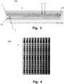
- Fig. 3 is illustrating a schematic example of renderings 130 of light travelling in the disclosed device.
- the rendering is based on a diffuser including a light guide 1, a diffusing layer 6, a first layer 2, a reflecting layer 3, and a second layer 7.
- the total length of the flat white guide is 10mm and the diffuser is arranged on human skin 7.
- the edge surface 10 is marked and the light enters the light guide 1 at the opposite side.
- the diffusing layer 6 has a refractive index which is the same refractive index, or at least close to the same refractive index, or higher than the light guide. If a first layer 2 is used, the layer should have a refractive index lower than the refractive index of the light guide 1 to obtain a total internal reflection.
- an optional second layer 7 is applied between the light guide 1 and the underlying material 13.
- the second layer 7 should have a refractive index having a lower value than the refractive index of the light guide 1.
- the second layer 7 may also have a refractive index which is closer to the refractive index of the underlying material 13 than the light guide 1.
- the second layer 7, may for example be an index matching layer or coating.
- a trilaminate is considered wherein the trilaminate has three layers with different refractive indexes.
- the second layer 7 of the rendering 130 does not only provide total internal reflection for some angles in the interface between the light guide 1 and the second layer 7, it also provides an index matching to increase the transmission between the emitting surface of the light guide 1 and the underlying material 13 for the light emitted out from the light emitting surface.
- the light guide On the top and on the side surfaces, the light guide has a final reflected layer 3 to make sure that light which may be transmitted out of the light guide is reflected back into the light guide.
- the layers used for the rendering 130 had the following properties: Layer Refractive index (760 nm) Thickness Ref number in Figs. Reflector (upper and near side relative light source) - - 3 Carrier 1.48 0.050 mm 2 Reflector adhesive 1.474 0.038 mm 2 Diffusing layer 1.8 - 6 Light guide 1.57 0.75 mm 1 Trilaminate, upper adhesive 1.474 0.062 mm 7 Trilaminate, carrier 1.48 0.028 mm 7 Trilaminate, lower adhesive 1.45 0.3 mm 7 Skin 1.4 (not illustrated) Total 1.22 mm
- the rendering 130 illustrates that areas being coated with a diffusing material reflect incident light with different angles than the angle of incidence. Some of this light may obtain a direction for which it is still trapped in the light guide by total internal reflection and other parts of the light may obtain a direction which allows it to exit the light guide through the light emitting surface.
- the rendering 130 also illustrates that the majority of the light that is not reflected in the interface between the light guide 1 and the second layer 2, is refracted and will enter the underlying skin 13. Only a small fraction of the light may reflect in the interface between the second layer 7 and the skin 13. This is due to a good refractive index matching between the second layer and the skin.
- Rendering 130 is therefore illustrating that the diffuser may provide the advantages of distributing the light over an area with low losses and a high output through the emitting surface.
- Fig. 4 is illustrating two hundred different schematic examples of patterns of diffusing material 140 that could be printed on a flat light guide, similar to the pattern illustrated in Fig. 3 . All of these patterns have varied number of white lines and with varied widths. What the patterns have in common is that they all start with an area of no printing close to where the light is coupled into the light guide and that the end with a larger area of white closer to the edge surface.
- Fig. 5 is illustrating a simulation of light intensity output 150 over an exemplary light emitting surface of the disclosed device. The light can again be seen to be distributed over the whole area, and hotspots are avoided.
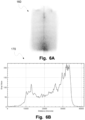
- Figs. 6A and 6B are illustrating a picture 160 showing the intensity over an emitting surface of an exemplary diffuser and the light intensity 170 along the dotted line.
- Fig. 6A is inverted for better contrast, depicting the light output in a grey scale. Again, this illustrates that the light is spread over the light emitting area and that there is no hotspot provided. It is also seen that the light intensity is low close to where the light is coupled into the diffuser and higher at the opposite end, but still low enough to avoid hotspots which could cause issues during spectroscopic measurements, or damages to the material being measured, such as human tissue, for example human skin.
- Fig. 7 is illustrating a schematic example of steps 180 for assembling a diffuser based on the disclosure herein:
- Fig. 8 is illustrating a schematic example of an assembled diffuser probe 190.
- the light emitting surface is seen and through that surface the diffusing layer 6 and reflecting layer 3 are also visible.
- the diffusing layer 6 is a printed white paint
- the reflective layer 6 is a copper tape. The copper tape is seen where no paint is applied on the light guide.
- This picture also illustrating that the initial part of the light guide 14, close to the waveguide used for coupling light into the diffuser 190, has no diffusing layer 3 applied as the reflective layer 3 is visible.
- Fig. 9 is illustrating a schematic example a flowchart 200 for a method of assembling a disclosed device.
- the method includes providing 101 a flat light guide having two larger flat surfaces on opposite sides and side surfaces. One of the two larger flat surfaces being a light emitting surface and the other surface being a back surface.
- the method may further include arranging 102 a connector for connecting a light to the flat light guide and arranging 103 a diffusing layer in contact with at least one of the two larger flat surfaces of the flat light guide.
Landscapes
- Physics & Mathematics (AREA)
- General Physics & Mathematics (AREA)
- Optics & Photonics (AREA)
- Light Guides In General And Applications Therefor (AREA)
- Planar Illumination Modules (AREA)
- Fastening Of Light Sources Or Lamp Holders (AREA)
Applications Claiming Priority (3)
| Application Number | Priority Date | Filing Date | Title |
|---|---|---|---|
| SE2030094 | 2020-03-20 | ||
| PCT/EP2021/056751 WO2021185880A1 (en) | 2020-03-20 | 2021-03-17 | A light diffuser and a method for assembling the same |
| EP21713361.0A EP4121689B1 (de) | 2020-03-20 | 2021-03-17 | Lichtdiffusor und verfahren zur montage davon |
Related Parent Applications (1)
| Application Number | Title | Priority Date | Filing Date |
|---|---|---|---|
| EP21713361.0A Division EP4121689B1 (de) | 2020-03-20 | 2021-03-17 | Lichtdiffusor und verfahren zur montage davon |
Publications (2)
| Publication Number | Publication Date |
|---|---|
| EP4474007A2 true EP4474007A2 (de) | 2024-12-11 |
| EP4474007A3 EP4474007A3 (de) | 2025-04-09 |
Family
ID=75111587
Family Applications (2)
| Application Number | Title | Priority Date | Filing Date |
|---|---|---|---|
| EP21713361.0A Active EP4121689B1 (de) | 2020-03-20 | 2021-03-17 | Lichtdiffusor und verfahren zur montage davon |
| EP24200639.3A Pending EP4474007A3 (de) | 2020-03-20 | 2021-03-17 | Lichtdiffusor |
Family Applications Before (1)
| Application Number | Title | Priority Date | Filing Date |
|---|---|---|---|
| EP21713361.0A Active EP4121689B1 (de) | 2020-03-20 | 2021-03-17 | Lichtdiffusor und verfahren zur montage davon |
Country Status (5)
| Country | Link |
|---|---|
| US (1) | US12585057B2 (de) |
| EP (2) | EP4121689B1 (de) |
| CN (1) | CN115380186A (de) |
| AU (1) | AU2021238633A1 (de) |
| WO (1) | WO2021185880A1 (de) |
Families Citing this family (1)
| Publication number | Priority date | Publication date | Assignee | Title |
|---|---|---|---|---|
| DE102021001512B4 (de) * | 2021-03-23 | 2023-03-16 | Mercedes-Benz Group AG | Zierteil mit einem Flächenlichtleiter |
Family Cites Families (21)
| Publication number | Priority date | Publication date | Assignee | Title |
|---|---|---|---|---|
| DE69418502T2 (de) * | 1993-02-01 | 2000-02-24 | Tosoh Corp | Vorrichtung zur Hintergrund-Beleuchtung |
| JP3551996B2 (ja) | 1995-08-25 | 2004-08-11 | 松下電器産業株式会社 | 医療用レーザプローブ |
| JPH11352479A (ja) | 1998-06-12 | 1999-12-24 | Dainippon Printing Co Ltd | バックライト装置及び透過型表示装置 |
| KR20020047653A (ko) * | 2000-12-13 | 2002-06-22 | 이승철 | 조명장치 |
| JP2005050654A (ja) * | 2003-07-28 | 2005-02-24 | Clariant Internatl Ltd | 面光源装置 |
| KR100606549B1 (ko) * | 2004-07-01 | 2006-08-01 | 엘지전자 주식회사 | 면 발광 장치용 도광판 및 그의 제조 방법 |
| US20090067190A1 (en) | 2006-01-24 | 2009-03-12 | Kimoto Co., Ltd. | Optical Film and Backlight Unit Using the Same |
| US20070239232A1 (en) | 2006-03-28 | 2007-10-11 | Eastman Kodak Company | Light guide based light therapy device |
| KR101227304B1 (ko) * | 2007-03-28 | 2013-01-29 | 코오롱인더스트리 주식회사 | 광학시트 |
| US8721149B2 (en) * | 2008-01-30 | 2014-05-13 | Qualcomm Mems Technologies, Inc. | Illumination device having a tapered light guide |
| US8301216B2 (en) | 2008-12-23 | 2012-10-30 | The Regents Of The University Of California | Method and apparatus for quantification of optical properties of superficial volumes using small source-to-detector separations |
| KR101710201B1 (ko) * | 2009-12-20 | 2017-02-27 | 엘지디스플레이 주식회사 | 광 가이드 부재 및 이를 포함하는 표시장치 |
| CN102156320B (zh) | 2011-02-25 | 2013-06-26 | 深圳市华星光电技术有限公司 | 侧入式导光板组件及背光模块 |
| WO2014020901A1 (ja) | 2012-08-01 | 2014-02-06 | パナソニック株式会社 | 光学シート、発光装置、光学シートの製造方法及び発光装置の製造方法 |
| US20140233258A1 (en) * | 2013-02-18 | 2014-08-21 | Changshu Sunrex Technology Co., Ltd. | Backlight module |
| WO2014199676A1 (ja) * | 2013-06-10 | 2014-12-18 | シャープ株式会社 | 導光体及びそれを備えた面状発光装置 |
| KR20150025576A (ko) * | 2013-08-29 | 2015-03-11 | 삼성디스플레이 주식회사 | 광학 플레이트, 이의 제조 방법, 및 이를 구비하는 백라이트 어셈블리 |
| CN106873072B (zh) * | 2017-04-24 | 2019-06-14 | 京东方科技集团股份有限公司 | 导光组件及其制备方法、背光模组和显示装置 |
| GB201717331D0 (en) | 2017-10-21 | 2017-12-06 | Optrical Ltd | Light guides |
| CN108415191A (zh) * | 2018-03-15 | 2018-08-17 | 京东方科技集团股份有限公司 | 显示装置、电子设备和显示方法 |
| JP7584213B2 (ja) * | 2018-10-09 | 2024-11-15 | 恵和株式会社 | 光学シート、バックライトユニット、液晶表示装置及び情報機器 |
-
2021
- 2021-03-17 WO PCT/EP2021/056751 patent/WO2021185880A1/en not_active Ceased
- 2021-03-17 EP EP21713361.0A patent/EP4121689B1/de active Active
- 2021-03-17 EP EP24200639.3A patent/EP4474007A3/de active Pending
- 2021-03-17 AU AU2021238633A patent/AU2021238633A1/en not_active Abandoned
- 2021-03-17 US US17/906,827 patent/US12585057B2/en active Active
- 2021-03-17 CN CN202180022770.4A patent/CN115380186A/zh active Pending
Also Published As
| Publication number | Publication date |
|---|---|
| WO2021185880A1 (en) | 2021-09-23 |
| EP4121689C0 (de) | 2024-09-18 |
| EP4121689A1 (de) | 2023-01-25 |
| EP4474007A3 (de) | 2025-04-09 |
| CN115380186A (zh) | 2022-11-22 |
| AU2021238633A1 (en) | 2022-09-29 |
| US12585057B2 (en) | 2026-03-24 |
| EP4121689B1 (de) | 2024-09-18 |
| US20230083665A1 (en) | 2023-03-16 |
Similar Documents
| Publication | Publication Date | Title |
|---|---|---|
| US10989863B2 (en) | Slim waveguide coupling apparatus and method | |
| CA2201795C (en) | Lighting system | |
| JP5643750B2 (ja) | 照明システム及びそのための光注入カプラ | |
| KR101965389B1 (ko) | 광-확산 광학 섬유를 사용하는 광-커플링 광학 시스템 및 그 방법 | |
| CN107430239B (zh) | 包括光导的照明系统 | |
| US7658514B2 (en) | Light guide, method and apparatus for manufacturing the same, and illuminating system having the same | |
| US20120033445A1 (en) | Luminaire with functionality-enhancing structure | |
| KR20000004931A (ko) | 다층 광학필름을 채용한 광가이드 | |
| KR20100094533A (ko) | 광도파관 | |
| KR20030019064A (ko) | 조명 장치 및 액정 표시 장치 | |
| WO2005068900A1 (ja) | リフレクタおよびバックライト装置 | |
| US11561337B2 (en) | Luminaire having a light guide with cladding | |
| CN115712213A (zh) | 一种光学膜片及背光模组 | |
| EP4121689B1 (de) | Lichtdiffusor und verfahren zur montage davon | |
| TWI587052B (zh) | 光源模組及顯示裝置 | |
| US20190346616A1 (en) | Modular light guide plate | |
| JP2012059612A (ja) | 面発光装置 | |
| JP2002197910A (ja) | 面照明装置 | |
| EP3218647A1 (de) | Beleuchtungssystem mit lichtleiter | |
| JP7765147B2 (ja) | 光照射装置及び光照射方法 | |
| KR102249867B1 (ko) | 광학 부재 및 이를 이용하는 조명 장치 | |
| CN215174304U (zh) | 一种导光板及灯具总成 | |
| TWI328126B (en) | Optical element and its production method | |
| KR101916736B1 (ko) | 광학부재 및 이를 포함하는 백라이트 유닛 | |
| KR20220111595A (ko) | 굴절 반사 구조를 활용한 무도광판 면 발광 장치 |
Legal Events
| Date | Code | Title | Description |
|---|---|---|---|
| PUAI | Public reference made under article 153(3) epc to a published international application that has entered the european phase |
Free format text: ORIGINAL CODE: 0009012 |
|
| STAA | Information on the status of an ep patent application or granted ep patent |
Free format text: STATUS: THE APPLICATION HAS BEEN PUBLISHED |
|
| AC | Divisional application: reference to earlier application |
Ref document number: 4121689 Country of ref document: EP Kind code of ref document: P |
|
| AK | Designated contracting states |
Kind code of ref document: A2 Designated state(s): AL AT BE BG CH CY CZ DE DK EE ES FI FR GB GR HR HU IE IS IT LI LT LU LV MC MK MT NL NO PL PT RO RS SE SI SK SM TR |
|
| REG | Reference to a national code |
Ref country code: DE Ref legal event code: R079 Free format text: PREVIOUS MAIN CLASS: A61N0005060000 Ipc: F21V0008000000 |
|
| PUAL | Search report despatched |
Free format text: ORIGINAL CODE: 0009013 |
|
| AK | Designated contracting states |
Kind code of ref document: A3 Designated state(s): AL AT BE BG CH CY CZ DE DK EE ES FI FR GB GR HR HU IE IS IT LI LT LU LV MC MK MT NL NO PL PT RO RS SE SI SK SM TR |
|
| RIC1 | Information provided on ipc code assigned before grant |
Ipc: A61N 5/06 20060101ALI20250305BHEP Ipc: G02B 5/02 20060101ALI20250305BHEP Ipc: F21V 8/00 20060101AFI20250305BHEP |
|
| STAA | Information on the status of an ep patent application or granted ep patent |
Free format text: STATUS: REQUEST FOR EXAMINATION WAS MADE |
|
| 17P | Request for examination filed |
Effective date: 20251009 |