EP4471275A2 - Multifunktionsluftpumpe - Google Patents
Multifunktionsluftpumpe Download PDFInfo
- Publication number
- EP4471275A2 EP4471275A2 EP24184625.2A EP24184625A EP4471275A2 EP 4471275 A2 EP4471275 A2 EP 4471275A2 EP 24184625 A EP24184625 A EP 24184625A EP 4471275 A2 EP4471275 A2 EP 4471275A2
- Authority
- EP
- European Patent Office
- Prior art keywords
- air pump
- air
- pump
- mode
- multifunctional
- Prior art date
- Legal status (The legal status is an assumption and is not a legal conclusion. Google has not performed a legal analysis and makes no representation as to the accuracy of the status listed.)
- Granted
Links
Images










Classifications
-
- F—MECHANICAL ENGINEERING; LIGHTING; HEATING; WEAPONS; BLASTING
- F04—POSITIVE - DISPLACEMENT MACHINES FOR LIQUIDS; PUMPS FOR LIQUIDS OR ELASTIC FLUIDS
- F04D—NON-POSITIVE-DISPLACEMENT PUMPS
- F04D27/00—Control, e.g. regulation, of pumps, pumping installations or pumping systems specially adapted for elastic fluids
- F04D27/004—Control, e.g. regulation, of pumps, pumping installations or pumping systems specially adapted for elastic fluids by varying driving speed
-
- F—MECHANICAL ENGINEERING; LIGHTING; HEATING; WEAPONS; BLASTING
- F04—POSITIVE - DISPLACEMENT MACHINES FOR LIQUIDS; PUMPS FOR LIQUIDS OR ELASTIC FLUIDS
- F04D—NON-POSITIVE-DISPLACEMENT PUMPS
- F04D25/00—Pumping installations or systems
- F04D25/02—Units comprising pumps and their driving means
- F04D25/08—Units comprising pumps and their driving means the working fluid being air, e.g. for ventilation
- F04D25/084—Units comprising pumps and their driving means the working fluid being air, e.g. for ventilation hand fans
-
- F—MECHANICAL ENGINEERING; LIGHTING; HEATING; WEAPONS; BLASTING
- F04—POSITIVE - DISPLACEMENT MACHINES FOR LIQUIDS; PUMPS FOR LIQUIDS OR ELASTIC FLUIDS
- F04D—NON-POSITIVE-DISPLACEMENT PUMPS
- F04D25/00—Pumping installations or systems
- F04D25/16—Combinations of two or more pumps ; Producing two or more separate gas flows
- F04D25/166—Combinations of two or more pumps ; Producing two or more separate gas flows using fans
-
- F—MECHANICAL ENGINEERING; LIGHTING; HEATING; WEAPONS; BLASTING
- F04—POSITIVE - DISPLACEMENT MACHINES FOR LIQUIDS; PUMPS FOR LIQUIDS OR ELASTIC FLUIDS
- F04D—NON-POSITIVE-DISPLACEMENT PUMPS
- F04D27/00—Control, e.g. regulation, of pumps, pumping installations or pumping systems specially adapted for elastic fluids
- F04D27/001—Testing thereof; Determination or simulation of flow characteristics; Stall or surge detection, e.g. condition monitoring
-
- F—MECHANICAL ENGINEERING; LIGHTING; HEATING; WEAPONS; BLASTING
- F04—POSITIVE - DISPLACEMENT MACHINES FOR LIQUIDS; PUMPS FOR LIQUIDS OR ELASTIC FLUIDS
- F04D—NON-POSITIVE-DISPLACEMENT PUMPS
- F04D27/00—Control, e.g. regulation, of pumps, pumping installations or pumping systems specially adapted for elastic fluids
- F04D27/008—Stop safety or alarm devices, e.g. stop-and-go control; Disposition of check-valves
-
- F—MECHANICAL ENGINEERING; LIGHTING; HEATING; WEAPONS; BLASTING
- F04—POSITIVE - DISPLACEMENT MACHINES FOR LIQUIDS; PUMPS FOR LIQUIDS OR ELASTIC FLUIDS
- F04D—NON-POSITIVE-DISPLACEMENT PUMPS
- F04D29/00—Details, component parts, or accessories
- F04D29/40—Casings; Connections of working fluid
- F04D29/42—Casings; Connections of working fluid for radial or helico-centrifugal pumps
- F04D29/4206—Casings; Connections of working fluid for radial or helico-centrifugal pumps especially adapted for elastic fluid pumps
- F04D29/4226—Fan casings
- F04D29/4246—Fan casings comprising more than one outlet
-
- F—MECHANICAL ENGINEERING; LIGHTING; HEATING; WEAPONS; BLASTING
- F04—POSITIVE - DISPLACEMENT MACHINES FOR LIQUIDS; PUMPS FOR LIQUIDS OR ELASTIC FLUIDS
- F04D—NON-POSITIVE-DISPLACEMENT PUMPS
- F04D29/00—Details, component parts, or accessories
- F04D29/40—Casings; Connections of working fluid
- F04D29/42—Casings; Connections of working fluid for radial or helico-centrifugal pumps
- F04D29/44—Fluid-guiding means, e.g. diffusers
- F04D29/46—Fluid-guiding means, e.g. diffusers adjustable
- F04D29/50—Fluid-guiding means, e.g. diffusers adjustable for reversing fluid flow
- F04D29/503—Fluid-guiding means, e.g. diffusers adjustable for reversing fluid flow especially adapted for elastic fluid pumps
-
- F—MECHANICAL ENGINEERING; LIGHTING; HEATING; WEAPONS; BLASTING
- F04—POSITIVE - DISPLACEMENT MACHINES FOR LIQUIDS; PUMPS FOR LIQUIDS OR ELASTIC FLUIDS
- F04D—NON-POSITIVE-DISPLACEMENT PUMPS
- F04D29/00—Details, component parts, or accessories
- F04D29/05—Shafts or bearings, or assemblies thereof, specially adapted for elastic fluid pumps
- F04D29/056—Bearings
-
- Y—GENERAL TAGGING OF NEW TECHNOLOGICAL DEVELOPMENTS; GENERAL TAGGING OF CROSS-SECTIONAL TECHNOLOGIES SPANNING OVER SEVERAL SECTIONS OF THE IPC; TECHNICAL SUBJECTS COVERED BY FORMER USPC CROSS-REFERENCE ART COLLECTIONS [XRACs] AND DIGESTS
- Y02—TECHNOLOGIES OR APPLICATIONS FOR MITIGATION OR ADAPTATION AGAINST CLIMATE CHANGE
- Y02B—CLIMATE CHANGE MITIGATION TECHNOLOGIES RELATED TO BUILDINGS, e.g. HOUSING, HOUSE APPLIANCES OR RELATED END-USER APPLICATIONS
- Y02B30/00—Energy efficient heating, ventilation or air conditioning [HVAC]
- Y02B30/70—Efficient control or regulation technologies, e.g. for control of refrigerant flow, motor or heating
Definitions
- the present disclosure relates to a multifunctional air pump. More particularly, the present disclosure relates to a multifunctional air pump for inflating and deflating an inflatable product, such as an inflatable mattress, and to a method for using the same.
- inflatable products have led to their adoption in a variety of household products, such as inflatable mattresses, inflatable pools and spas, inflatable furniture, and other inflatable products.
- inflatable products are susceptible to air leakage due to material deformation and/or long-term stress, which affects the user's comfort.
- an inflatable mattress for example, the user may fill the bed to an initial pressure to achieve a desired hardness, but the mattress may leak air over time and become softer and softer.
- the present disclosure provides a multifunctional air pump for inflating and deflating an inflatable product.
- the multifunctional air pump includes an air pump assembly, a control module, and a remote user input.
- the air pump may be operated remotely for convenience.
- the air pump may also operate automatically to maintain the pressure of the inflatable product.
- a multifunctional air pump including an air pump assembly and a control module.
- the air pump assembly includes a first opening in fluid communication with a surrounding atmosphere, a second opening in fluid communication with an inflatable product, a pump having an inlet and an outlet, and an air passageway having a first position in which the inlet of the pump communicates with the first opening and the outlet of the pump communicates with the second opening and a second position in which the inlet of the pump communicates with the second opening and the outlet of the pump communicates with the first opening.
- the control module is in electrical communication with the air pump assembly and has at least one communication module that is configured to communicate with a remote user input.
- control module is configured to operate the air pump assembly in an inflation mode with the pump on and the air passageway positioned in the first position and a deflation mode with the pump on and the air passageway positioned in the second position.
- control module is configured to operate the air pump assembly in an adjustment mode with the pump off and the air passageway positioned in the second position.
- the remote user input includes an inflation button corresponding to the inflation mode, a deflation button corresponding to the deflation mode, and an adjustment button corresponding to the adjustment mode.
- control module is configured to operate the air pump assembly in a pressure maintenance mode with the pump on at a lower speed than the inflation mode and the air passageway positioned in the first position.
- control module operates a driving device that automatically rotates the air passageway between the first and second positions.
- the air passageway is located within a core, and the driving device rotates the core by moving a rack having a geared relationship with the core.
- a hand wheel is provided to manually rotate the air passageway between the first and second positions.
- control module controls operation of the pump based on at least one of a timer, a pressure detector, and a current detector.
- a valve is located in the second opening, wherein the valve is biased closed when the air passageway is in the first position and is forced open when the air passageway is in the second position.
- the air passageway when the air passageway is in the second position, the air passageway is offset from a central axis of the pump.
- the at least one communication module includes a WIFI chip, a Bluetooth chip, or an infrared chip.
- the remote user input is one of a smartphone, a tablet, and a computer.
- the remote user input is a dedicated remote control.
- the air pump assembly is built into the inflatable product.
- the inflatable product is a mattress.
- a multifunctional air pump including an air pump assembly and a control module.
- the air pump assembly includes an air pump in fluid communication with an inflatable product and a surrounding atmosphere, wherein the air pump assembly is operable in an inflation mode in which the air pump assembly inflates the inflatable product by operating the air pump and directing air from the surrounding atmosphere to the inflatable product, a deflation mode in which the air pump assembly deflates the inflatable product by operating the air pump and directing air from the inflatable product to the surrounding atmosphere, and an adjustment mode in which the air pump assembly gradually deflates the inflatable product by allowing air to travel from the inflatable product to the surrounding atmosphere without operating the air pump.
- the control module is in electrical communication with the air pump assembly, the control module being configured to receive a user command and to operate the air pump assembly in one of the inflation, deflation, and adjustment modes based on the user command.
- the air pump assembly includes a moveable air passageway having a first position in the inflation mode and a second position in the deflation and adjustment modes.
- control module automatically moves the air passageway between the first and second positions.
- a multifunctional air pump including an air pump assembly and a control module.
- the air pump assembly includes an air pump in fluid communication with an inflatable product and a surrounding atmosphere, wherein the air pump assembly is operable in an inflation mode in which the air pump assembly inflates the inflatable product by operating the air pump at a first speed and directing air from the surrounding atmosphere to the inflatable product, a deflation mode in which the air pump assembly deflates the inflatable product by operating the air pump and directing air from the inflatable product to the surrounding atmosphere, and a maintenance mode in which the air pump assembly maintains inflation of the inflatable product by operating the air pump at a second speed lower than the first speed and directing air from the surrounding atmosphere to the inflatable product.
- the control module is in electrical communication with the air pump assembly, the control module being configured to receive a user command and to operate the air pump assembly in one of the inflation, deflation, and maintenance modes based on the user command.
- control module communicates with at least one of a timer, a pressure detector, and a current detector in the maintenance mode.
- control module stops operating the air pump in the maintenance mode when the inflatable product reaches a predetermined pressure.
- the predetermined pressure is adjustable by a user.
- the air pump is coupled to an air admission valve that closes in the inflation and deflation modes and opens in the maintenance mode.
- the air pump is coupled to the air admission valve via a one-way bearing.
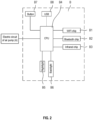
- a multifunctional air pump including an air pump assembly A, a control module B, and a remote user input C.
- the air pump assembly A communicates with an inflatable product D, such as an inflatable mattress, an inflatable pool or spa, an inflatable furniture item, or another inflatable product.
- the air pump assembly A is built into or otherwise coupled to the inflatable product D.
- the control module B is electrically coupled to the air pump assembly A and is wirelessly coupled to the remote user input C for communication therewith.
- the communication between the control module B and the remote user input C may be one-way or two-way.
- the illustrative control module B includes at least one communication module, such as a WIFI chip B1, a Bluetooth chip B2, and/or an infrared chip B3.
- the control module B also includes a central processing unit (CPU) B4 connected to and configured to control the communication modules B1, B2, B3.
- the CPU B4 is also connected to and configured to control a nightlight B5, a backlight B6, at least one button B7, and a USB port B8.
- air pump assembly A may have various modes of operation.
- the backlight B6 may be used for communicating the working state of air pump assembly A to the user, and the button B7 may be used for selecting the desired mode of operation.
- the USB port B8 is configured to receive, power, and/or operate a USB-enabled device, such as a cell phone or a music player.
- the control module B is coupled to a power supply (not shown).
- the power supply may be an internal battery or an external power source, such as a standard electrical outlet.
- the illustrative remote user input C is configured to receive user commands and communicate those commands to the air pump assembly A via the control module B.
- An exemplary remote user input C includes a remote control that is sold with and dedicated to the control module B.
- Other exemplary terminals C include smartphones, tablets, or computers, for example, having software installed thereon to communicate with the control module B.
- the remote user input C may include a plurality of user inputs, such as an inflation button C1, a deflation button C2, and/or an adjustment button C3.
- the user may input commands to the remote user input C to control operation of the air pump assembly A via one or more communication modules of the control module B, such as the WIFI chip B1, the Bluetooth chip B2, and/or the infrared chip B3 of the control module B.
- the control module B such as the WIFI chip B1, the Bluetooth chip B2, and/or the infrared chip B3 of the control module B.
- the command may be sent to an appropriate communication module B1, B2, B3, of the control module B and then to the CPU B4 of the control module B to operate the air pump assembly A in an inflation mode.
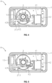
- a first embodiment of the air pump assembly A includes a seat or housing 1, an air pump 2 located within the housing 1, a moveable air core 3, and an automatic operation mechanism 4.
- the housing 1 may be built into an inflatable chamber of the inflatable product D ( FIG. 1 ).
- the housing 1 includes a cover panel 11 with a first opening 111 in fluid communication with the surrounding atmosphere.
- the housing 1 also includes a second opening or vent 12 in fluid communication with the inflatable product.
- the vent 12 is controlled by a one-way check valve 13 that is biased closed.
- the cover panel 11 includes an inflation switch or button 112, a deflation switch or button 113, an adjustment switch or button 114, and an indicator light 115 for displaying whether the system is operational, as described further below.
- the air pump 2 includes a body 21, a blade 22, and a motor 23 that drives the blade 22.
- the body 21 defines an air inlet 211 and air outlet 212, wherein the air inlet 211 is arranged along the central axis of the blade 22 and the air outlet 212 is arranged tangent to the blade 22.
- the blade 22 is received within the body 21 and may include a single blade or multiple blade groups. In operation, the blade 22 draws air into the air inlet 211 and exhausts air through the air outlet 212.
- the air core 3 has an internal passageway 31 in fluid communication with the opening 111 of the housing 1 on one end (i.e., the top end in FIG. 3 ) and in selective fluid communication with the air pump 2 on the other end (i.e., the bottom end in FIG. 3 ).
- the air core 3 is configured to rotate, swing, or otherwise move to selectively communicate with the air inlet 211 or the air outlet 212 of the air pump 2.
- the internal passageway 31 of the air core 3 may have a horn shape and may extend along or eccentric to a central axis of the air pump 2.
- the one-way valve 13 may be opened using the automatic operation mechanism 4, as discussed further below.
- the external surface of the air core 3 may have an eccentric setting such that the air core 3 forms a cam surface that is configured to selectively push the one-way valve 13 and open the vent 12.
- the circuit board 42 may correspond to the CPU B4 of the control module B
- the buttons 112, 113 may correspond to the button B7 of the control module B
- the light 115 may correspond to one of the lights B5, B6 of the control module B.
- the inflation mode is shown in FIGS. 4 and 6 .
- the passageway 31 of the air core 3 communicates with the air inlet 211 of the air pump 2.
- the air inlet 211 of the air pump 2 communicates with the surrounding atmosphere via the passageway 31 and the opening 111, while the air outlet 212 of the air pump 2 communicates with the inflatable product via the vent 12.
- the motor 23 of the air pump 2 begins to operate.
- the one-way valve 13 opens under the air pressure from the air pump 2 to allow air to enter and inflate the inflatable product via the open vent 12.
- Operating the inflation button 112 also causes the timer on the circuit board 42 to start timing.
- the motor 23 of the air pump 2 will stop operating. Thus, the user is able to interrupt the inflation mode by operating the inflation button 112 a second time. Otherwise, the motor 23 will continue operating until the timer expires after a predetermined time period. According to an exemplary embodiment, this time period is selected and programmed to ensure that the corresponding inflatable product is fully inflated when the timer expires.
- the predetermined time may be about 3 to 8 minutes, more specifically about 5 to 6 minutes.
- the deflation mode is shown in FIGS. 5 and 7 .
- the motor 23 of the air pump 2 and the driving device 41 of the operation mechanism 4 both begin to operate simultaneously.
- the driving device 41 retracts the rack 43, and the rack 43 rotates the air core 3 so that the passageway 31 moves from the air inlet 211 of the air pump 2 to the air outlet 212 of the air pump 2.
- the air inlet 211 of the air pump 2 communicates with the inflatable product via the vent 12, while the air outlet 212 of the air pump 2 communicates with the surrounding atmosphere via the passageway 31 and the opening 111.
- the pull rod 431 of the rack 43 contacts and pivots the push rod 213 into engagement with the one-way valve 13, thereby forcing the one-way valve 13 open.
- the air inlet 211 of the air pump 2 draws air out of and deflates the inflatable product via the open vent 12.
- Operating the deflation button 113 also causes the timer on the circuit board 42 to start timing. If the user operates the deflation button 113 a second time, both the motor 23 of the air pump 2 and the driving device 41 of the operation mechanism 4 will stop operating. Thus, the user is able to interrupt the deflation mode by operating the deflation button 113 a second time.
- this time period is selected and programmed to ensure that the corresponding inflatable product is fully deflated when the timer expires.
- the predetermined time may be about 3 to 8 minutes, more specifically about 5 to 6 minutes.
- the adjustment mode is shown in FIG. 8 .
- the driving device 41 operates and retracts the rack 43 to the retracted position shown in FIG. 5 .
- the pull rod 431 of the rack 43 contacts and pivots the push rod 213 into engagement with the one-way valve 13, thereby forcing the one-way valve 13 open.
- the motor 23 of the air pump 2 may not be operating, air from the inflatable product may gradually leak out of and deflate the inflatable product via the open vent 12.
- the user may use the adjustment mode when the inflatable product is too hard and requires a slight or gradual pressure adjustment.
- the driving device 41 stops operating, and the rack 43 returns to the extended position shown in FIG. 4 . In this extended position, the pull rod 431 of the rack 43 releases the push rod 213 and allows the one-way valve 13 to close.
- the air pump assembly A may be controlled remotely using the remote user input C, as discussed above with respect to FIGS. 1 and 2 .
- the air pump assembly A may also be controlled directly at the air pump assembly A.
- the control module B may enter: (1) the inflation mode when the user presses the inflation button C1 on the remote user input C or the inflation button 112 located on the air pump assembly A; (2) the deflation mode when the user presses the deflation button C2 on the remote user input C or the deflation button 113 located on the air pump assembly A; and (3) the adjustment mode when the user presses the adjustment button C3 on the remote user input C or the adjustment button 114 located on the air pump assembly A.
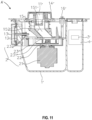
- the second air pump assembly A' includes a seat or housing 1', an air pump 2' located within the housing 1', and various other features in common with the first air pump assembly A, except as described below. Some of the elements discussed below may be considered part of the control module B ( FIGS. 1 and 2 ).
- the housing 1' may be built into an inflatable chamber of the inflatable product D ( FIG. 1 ).
- the housing 1' includes an opening 11' in fluid communication with the surrounding atmosphere.
- the housing 1' also includes an opening or vent 12' in fluid communication with the inflatable product.
- the vent 12' is controlled by a one-way check valve 13' that is biased closed.
- the housing 1' also includes a timer 3' and a current detector 4'.
- the housing 1' may include a first chamber for the air pump 2' and a separate chamber for the timer 3' and the current detector 4' such that the air pump 2' is at least partially separated from the timer 3' and the current detector 4'.
- the second air pump assembly A' also includes an air core 15' rotatably coupled to a hand wheel 14'. It is also within the scope of the present disclosure that the air core 15' may be rotated automatically using the automatic operation mechanism 4 of FIGS. 3-8 or another suitable mechanism.
- the opening 11' may extend through the hand wheel 14'.
- the air core 15' includes an internal passageway 151' in fluid communication with the opening 11' on one end (i.e., the top end in FIG. 11 ) and in selective fluid communication with the air pump 2' on the other end (i.e., the bottom end in FIG. 11 ).
- the illustrative internal passageway 151' has a horn shape and extends eccentric to a central axis of the air pump 2'.
- the external surface of the air core 15' has an eccentric setting such that the air core 15' includes a cam 152' that is configured to selectively push the one-way valve 13' and open the vent 12'.
- the air pump 2' includes a body 23', a blade 22', and a motor 21' that drives the blade 22'.
- the body 23' of the air pump 2' includes an air inlet 231' and an air outlet 232', wherein the air inlet 231' is arranged along the central axis of the blade 22' and the air outlet 232' is arranged tangent to the blade 22'.
- the blade 22' draws air into the air inlet 231' and exhausts air through the air outlet 232'.
- the motor 21' of the air pump 2' is a two-speed motor having a high-speed rotary gear and a low-speed rotary gear. As shown in FIGS. 9 and 10 , the motor 21' is controlled via a gear switch 16' that is located adjacent to the hand wheel 14' for access by the user.
- the gear switch 16' may have a neutral state (e.g., "0"), a high-speed state (e.g., "1"), and a low-speed state (e.g., "2").
- the illustrative gear switch 16' is a 3-position rocker switch, but it is also within the scope of the present disclosure that the gear switch 16' may have buttons corresponding to each state.
- the motor 21' When the gear switch 16' is in the neutral state or position, the motor 21' is turned off. When the gear switch 16' is in the high-speed state or position, the motor 21' operates in the high-speed gear. When the gear switch 16' is in the low-speed state or position, the motor 21' operates in the low-speed gear.
- the motor 21', the timer 3', the current detector 4', the gear switch 16', and the power supply form an electrical circuit of the air pump assembly A'.
- the air pump assembly A' is configured to operate in an inflation mode, a deflation mode, and a pressure maintenance mode. Each mode of operation is described further below.
- the inflation mode is shown in FIGS. 12 and 14 .
- the user turns the hand wheel 14' to align the passageway 151' of the air core 15' with the air inlet 231' of the air pump 2'.
- the air inlet 231' of the air pump 2' communicates with the surrounding atmosphere via the passageway 151' and the opening 11', while the air outlet 232' of the air pump 2' communicates with the inflatable product via the vent 12'.
- the gear switch 16' to the high-speed position (e.g., "1"
- the motor 21' of the air pump 2' begins to operate in the high-speed gear.
- the one-way valve 13' opens under the air pressure from the air pump 2' to allow air to enter and inflate the inflatable product via the open vent 12'. Pressing the gear switch 16' to the high-speed position also causes the timer 3' to start timing. If the user moves the gear switch 16' back to the neutral position (e.g., "0"), the motor 21' of the air pump 2' will stop operating. Thus, the user is able to interrupt the inflation mode by operating the gear switch 16'. Otherwise, the motor 21' will continue operating until the timer expires after a predetermined time period. According to an exemplary embodiment, this time period is selected and programmed to ensure that the corresponding inflatable product is fully inflated when the timer expires.
- the predetermined time may be about 3 to 8 minutes, more specifically about 5 to 6 minutes.
- the one-way valve 13' returns to its normally closed position to close the vent 12' and maintain the pressure of the inflatable product.
- the deflation mode is shown in FIGS. 13 and 14 .
- the user turns the hand wheel 14' to align the passageway 151' of the air core 15' with the air outlet 232' of the air pump 2'.
- the air inlet 231' of the air pump 2' communicates with the inflatable product via the vent 12'
- the air outlet 232' of the air pump 2' communicates with the surrounding atmosphere via the passageway 151' and the opening 11'.
- the cam 152' of the air core 15' contacts and forces the one-way valve 13' open.
- the motor 21' of the air pump 2' begins to operate in the high-speed gear. With the motor 21' running, the air inlet 231' of the air pump 2' draws air out of and deflates the inflatable product via the open vent 12'. Pressing the gear switch 16' to the high-speed position also causes the timer 3' to start timing. If the user moves the gear switch 16' back to the neutral position (e.g., "0"), the motor 21' of the air pump 2' will stop operating. Thus, the user is able to interrupt the deflation mode by operating the gear switch 16'. Otherwise, the motor 21' will continue operating until the timer expires after a predetermined time period.
- this time period is selected and programmed to ensure that the corresponding inflatable product is fully deflated when the timer expires.
- the predetermined time may be about 3 to 8 minutes, more specifically about 5 to 6 minutes.
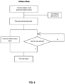
- the pressure maintenance mode is shown in FIG. 15 .
- the user turns the hand wheel 14' to align the passageway 151' of the air core 15' with the air inlet 231' of the air pump 2', like the inflation mode of FIG. 12 .
- the gear switch 16' moves to the low-speed position (e.g., "2")
- the motor 21' of the air pump 2' begins to operate in the low-speed gear.
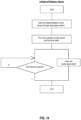
- the one-way valve 13' opens under the air pressure from the air pump 2' to allow air to enter and inflate the inflatable product via the open vent 12'. Pressing the gear switch 16' to the low-speed position also causes the current detector 4' to start operating.
- the current of the motor 21' increases, and this increasing current is detected by the current detector 4'.
- the motor 21' continues its low-speed operation until the detected current reaches a predetermined set point.
- this set point is selected and programmed to ensure that the corresponding inflatable product is fully inflated.
- the motor 21' stops operating, and the timer 3' starts timing.
- the process automatically repeats to continue maintaining the pressure of the inflatable product and ensuring the inflatable product's normal use and comfort.
- the user can interrupt the pressure maintenance mode and stop the motor 21' by moving the gear switch 16' back to the neutral position (e.g., "0").
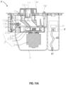
- an electronic pressure detector 6' is provided to monitor the pressure inside the inflatable product.
- An exemplary pressure detector 6' is shown in FIG. 11A and includes a detection hole 61' in fluid communication with the inflatable product and a tube 62' extending between the detection hole 61' and the pressure detector 6'.
- the motor 21' running, the pressure in the inflatable product gradually increases. This increasing pressure is detected by the pressure detector 6' through the detection hole 61' and the tube 62'.
- the motor 21' continues its low-speed operation until the detected pressure reaches a predetermined set point.
- this set point is selected and programmed to ensure that the corresponding inflatable product is fully inflated.
- the pressure set point may be about 0.1 psi, 0.2 psi, 0.3 psi, 0.4 psi, or more.
- the pressure maintenance mode may continue according to FIG. 15 .
- Table 1 Mode Check Valve 13'
- Hand Wheel 14'
- Gear Switch (16') Detector (4' or 6') Off Biased closed -- Neutral state Inactive Inflation Biased closed but opens under pressure from pump 2' Aligned with air inlet 231' of pump 2' High-speed state Inactive Deflation Forced open Aligned with air outlet 232' of pump 2' High-speed state Inactive Pressure Maintenance Biased closed but opens under pressure from pump 2' Aligned with air inlet 231' of pump 2' Low-speed state Active
- the air pump assembly A' may be controlled remotely using the remote user input C, as discussed above with respect to FIGS. 1 and 2 .
- the user may press buttons on the remote user input C corresponding to the gear switch 16' on the air pump assembly A'.
- the air pump assembly A' may also be controlled directly by pressing the gear switch 16' on the air pump assembly A'.
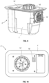
- the third air pump assembly A" includes a seat or housing 1", an air pump 2" located within the housing 1", and various other features in common with the first and second air pump assemblies A, A', except as described below. Some of the elements discussed below may be considered part of the control module B ( FIGS. 1 and 2 ).
- the housing 1" may be built into an inflatable chamber of the inflatable product D ( FIG. 1 ).
- the housing 1" includes an opening 11" in fluid communication with the surrounding atmosphere.
- the housing 1" also includes an opening or vent 12" in fluid communication with the inflatable product.
- the vent 12" is controlled by a one-way check valve 13" that is biased closed.
- the housing 1" also includes a cover panel 10" with an indicator light 101" and a digital display 102".
- the housing 1" further includes a detection hole 17" in fluid communication with the inflatable product, an electronic pressure detector 18", and a tube 19" extending between the detection hole 17" and the pressure detector 18".
- the air pump assembly A" also includes an air core 15" rotatably coupled to a hand wheel 14". It is also within the scope of the present disclosure that the air core 15" may be rotated automatically using the automatic operation mechanism 4 of FIGS. 3-8 or another suitable mechanism.
- the opening 11" may extend through the hand wheel 14".
- the air core 15" includes an internal passageway 151" in fluid communication with the opening 11" on one end (i.e., the top end in FIG. 18 ) and in selective fluid communication with the air pump 2" on the other end (i.e., the bottom end in FIG. 18 ).
- the illustrative internal passageway 151" has a horn shape and extends eccentric to a central axis of the air pump 2".
- the external surface of the air core 15" has an eccentric setting such that the air core 15" includes a cam 152" that is configured to selectively push the one-way valve 13" and open the vent 12".
- the air pump 2' includes a body 23", a blade 22", and a motor 21" that drives the blade 22".
- the body 23" of the air pump 2' includes an air inlet 231" and an air outlet 232", wherein the air inlet 231" is arranged along the central axis of the blade 22" and the air outlet 232" is arranged tangent to the blade 22". In operation, the blade 22" draws air into the air inlet 231" and exhausts air through the air outlet 232".
- the motor 21" of the air pump 2" is a two-speed motor having a high-speed rotary gear and a low-speed rotary gear. As shown in FIGS. 16 and 17 , the motor 21" is controlled via a gear switch 16" that is located adjacent to the hand wheel 14" on the cover panel 10" of the housing 1" for access by the user.
- the gear switch 16" may have a high-speed state corresponding to a high-speed button 161", a low-speed state corresponding to a low-speed button 162", and an otherwise neutral state. It is also within the scope of the present disclosure that the gear switch 16" may be a 3-position rocker switch like gear switch 16' of FIGS. 9 and 10 .
- the motor 21" When the gear switch 16" is in the neutral state, the motor 21" is turned off. When the gear switch 16" is in the high-speed state, the motor 21" operates in the high-speed gear. When the gear switch 16" is in the low-speed state, the motor 21" operates in the low-speed gear. In this embodiment, the motor 21", the pressure detector 18", the gear switch 16", and the power supply form an electrical circuit of the air pump assembly A".
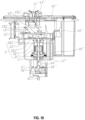
- the air pump assembly A" further includes a supplemental air admission system 3" located at the bottom of the housing 1" in FIGS. 18 and 19 .
- the air admission system 3" includes an air admission hole 31" selectively sealed by an air admission valve 32", which is coupled to the motor 21" via a connecting rod 33" and a one-way bearing 34".
- the motor 21" may rotate the connecting rod 33" in a first direction in the high-speed gear and in an opposite, second direction in the low-speed gear.
- the connecting rod 33" may engage the one-way bearing 34" in the second direction such that the one-way bearing 34" allows the motor 21" to drive the air admission valve 32" in the low-speed gear without driving the air admission valve 32" in the high-speed gear.
- the air pump assembly A" is configured to operate in an inflation mode, a deflation mode, and a pressure maintenance mode.
- the indicator light 101" may illuminate in one or more modes of operation whenever motor 21" is running. Each mode of operation is described further below.
- the inflation mode is shown in FIG. 18 .
- the user turns the hand wheel 14" to align the passageway 151" of the air core 15" with the air inlet 231" of the air pump 2".
- the air inlet 231" of the air pump 2" communicates with the surrounding atmosphere via the passageway 151" and the opening 11", while the air outlet 232" of the air pump 2" communicates with the inflatable product via the vent 12".
- the motor 21" of the air pump 2" begins to operate in the high-speed gear.
- the one-way valve 13" opens under the air pressure from the air pump 2" to allow air to enter and inflate the inflatable product via the open vent 12".
- the deflation mode is shown in FIG. 19 .
- the user turns the hand wheel 14" to align the passageway 151" of the air core 15" with the air outlet 232" of the air pump 2".
- the air inlet 231" of the air pump 2" communicates with the inflatable product via the vent 12
- the air outlet 232" of the air pump 2” communicates with the surrounding atmosphere via the passageway 151" and the opening 11".
- the cam 152" of the air core 15" contacts and forces the one-way valve 13" open.
- the motor 21" of the air pump 2" begins to operate in the high-speed gear.
- the air inlet 231" of the air pump 2" draws air out of and deflates the inflatable product via the open vent 12".
- the motor 21" of the air pump 2" stops.
- the pressure maintenance mode is shown in FIG. 20 .
- the user turns the hand wheel 14" to align the passageway 151" of the air core 15" with the air inlet 231" of the air pump 2", like the inflation mode of FIG. 18 .
- the pressure detector 18" begins operating.
- the pressure detector 18" may determine the pressure inside the inflatable product via the detection hole 17" and the tube 19". As long as the pressure inside the inflatable product is below a predetermined minimum set point, the pressure detector 18" may close the electrical circuit to the motor 21", and the motor 21" may begin operating the in the low-speed mode.
- the low-speed motor 21" opens the air admission valve 32" of the supplemental air admission system 3", which allows air to enter and inflate the inflatable product through the open admission hole 31". In this way, the supplemental air admission system 3" maintains the pressure of the inflatable product to ensure the inflatable product's normal use and comfort.
- the pressure detector 18" may open the electrical circuit and stop the motor 21" when the pressure inside the inflatable product reaches a predetermined maximum set point.
- the minimum and maximum pressure set points may be adjusted by the user, such as by pressing the low-speed button 162" of the gear switch 16" multiple times.
- Exemplary pressure set points are provided in Table 2 below, but these set points may vary to accommodate different inflatable products and user preferences.
- Table 2 Button (162") Display (102") Air Pump (2") Admission System (3") Min. Pressure (mm H 2 O) Max. Pressure (mm H 2 O) Press 1 time 0 Off Closed -- -- Press 2 times 1 Low-speed gear Open 180 200 Press 3 times 2 Low-speed gear Open 200 220 Press 4 times 3 Low-speed gear Open 230 250
- Pressing the low-speed button 162" of the gear switch 16" another time may repeat the cycle set forth in Table 2 above.
- the air pump assembly A" may be controlled remotely using the remote user input C, as discussed above with respect to FIGS. 1 and 2 .
- the user may press buttons on the remote user input C corresponding to the high-speed button 161" and the low-speed button 162" of the gear switch 16" on the air pump assembly A".
- the air pump assembly A" may also be controlled directly by pressing high-speed button 161" and the low-speed button 162" of the gear switch 16" on the air pump assembly A".
Landscapes
- Engineering & Computer Science (AREA)
- Mechanical Engineering (AREA)
- General Engineering & Computer Science (AREA)
- Physics & Mathematics (AREA)
- Fluid Mechanics (AREA)
- Mattresses And Other Support Structures For Chairs And Beds (AREA)
- Reciprocating Pumps (AREA)
- Chair Legs, Seat Parts, And Backrests (AREA)
Applications Claiming Priority (11)
| Application Number | Priority Date | Filing Date | Title |
|---|---|---|---|
| CN201520799262.9U CN205064308U (zh) | 2015-10-16 | 2015-10-16 | 充气产品的多功能泵 |
| CN201520898479 | 2015-11-12 | ||
| CN201520959301 | 2015-11-27 | ||
| CN201620247404 | 2016-03-29 | ||
| CN201610329403.XA CN105952663A (zh) | 2015-11-12 | 2016-05-18 | 一种多功能充放气泵 |
| CN201620452544.6U CN205744550U (zh) | 2016-05-18 | 2016-05-18 | 充气产品的智能补气泵 |
| CN201620452597.8U CN205991022U (zh) | 2016-03-29 | 2016-05-18 | 充气产品的辅助补气泵 |
| CN201620452516.4U CN205779836U (zh) | 2015-11-27 | 2016-05-18 | 换气装置的自动换向操作机构 |
| CN201620452545.0U CN205779787U (zh) | 2015-11-12 | 2016-05-18 | 充气产品的自动补气泵 |
| PCT/IB2016/001484 WO2017064553A1 (en) | 2015-10-16 | 2016-10-14 | Multifunctional air pump |
| EP16855009.3A EP3362688B1 (de) | 2015-10-16 | 2016-10-14 | Multifunktionale luftpumpe |
Related Parent Applications (1)
| Application Number | Title | Priority Date | Filing Date |
|---|---|---|---|
| EP16855009.3A Division EP3362688B1 (de) | 2015-10-16 | 2016-10-14 | Multifunktionale luftpumpe |
Publications (3)
| Publication Number | Publication Date |
|---|---|
| EP4471275A2 true EP4471275A2 (de) | 2024-12-04 |
| EP4471275A3 EP4471275A3 (de) | 2025-03-05 |
| EP4471275B1 EP4471275B1 (de) | 2026-08-19 |
Family
ID=58517063
Family Applications (2)
| Application Number | Title | Priority Date | Filing Date |
|---|---|---|---|
| EP24184625.2A Active EP4471275B1 (de) | 2015-10-16 | 2016-10-14 | Multifunktionsluftpumpe |
| EP16855009.3A Active EP3362688B1 (de) | 2015-10-16 | 2016-10-14 | Multifunktionale luftpumpe |
Family Applications After (1)
| Application Number | Title | Priority Date | Filing Date |
|---|---|---|---|
| EP16855009.3A Active EP3362688B1 (de) | 2015-10-16 | 2016-10-14 | Multifunktionale luftpumpe |
Country Status (3)
| Country | Link |
|---|---|
| US (1) | US10851795B2 (de) |
| EP (2) | EP4471275B1 (de) |
| WO (1) | WO2017064553A1 (de) |
Families Citing this family (26)
| Publication number | Priority date | Publication date | Assignee | Title |
|---|---|---|---|---|
| US10711788B2 (en) | 2015-12-17 | 2020-07-14 | Wayne/Scott Fetzer Company | Integrated sump pump controller with status notifications |
| US10273966B2 (en) * | 2016-03-02 | 2019-04-30 | Sun Pleasure Company Limited | Built-in air pump |
| CN206368786U (zh) | 2016-12-08 | 2017-08-01 | 明达实业(厦门)有限公司 | 泵与充气产品的连接结构 |
| USD893552S1 (en) | 2017-06-21 | 2020-08-18 | Wayne/Scott Fetzer Company | Pump components |
| CN208669644U (zh) * | 2018-05-16 | 2019-03-29 | 明达实业(厦门)有限公司 | 一种具有多通道充放气功能的泵浦 |
| US11549514B2 (en) | 2017-11-27 | 2023-01-10 | Intex Marketing Ltd. | Manual inflation and deflation adjustment structure for a pump |
| USD890211S1 (en) | 2018-01-11 | 2020-07-14 | Wayne/Scott Fetzer Company | Pump components |
| CN108317097B (zh) * | 2018-02-01 | 2024-11-05 | 江苏亿美电器有限公司 | 充气泵 |
| CN209164045U (zh) * | 2018-11-19 | 2019-07-26 | 浙江锐韦机电科技有限公司 | 泵阀一体机构 |
| CN209212629U (zh) * | 2018-12-24 | 2019-08-06 | 上海荣威塑胶工业有限公司 | 用于充气体的内置气泵 |
| CN209586640U (zh) * | 2019-01-31 | 2019-11-05 | 上海荣威塑胶工业有限公司 | 内置气泵及充气体装置 |
| CN209875430U (zh) * | 2019-02-12 | 2019-12-31 | 上海荣威塑胶工业有限公司 | 智能电动气泵 |
| CN212155088U8 (zh) | 2019-06-21 | 2021-03-05 | 上海荣威塑胶工业有限公司 | 充气产品 |
| ES2928384T3 (es) | 2019-06-21 | 2022-11-17 | Intex Marketing Ltd | Producto inflable que tiene bombas eléctricas y manuales |
| EP4414560B1 (de) * | 2019-06-21 | 2025-12-03 | Bestway Inflatables & Material Corp. | Luftpumpe für ein aufblasbares produkt und aufblasbares produkt mit eingebauter luftpumpe |
| CN211009180U (zh) | 2019-07-02 | 2020-07-14 | 明达实业(厦门)有限公司 | 一种高低压一体充气泵和充气产品 |
| EP3994357A4 (de) | 2019-07-05 | 2023-06-07 | Intex Industries Xiamen Co. Ltd | Diversifizierte und abnehmbare pumpsysteme sowie verfahren zum aufblasen und entleeren von aufblasbaren gegenständen |
| CN110242614B (zh) * | 2019-07-16 | 2024-08-27 | 中山骏宏塑胶制品有限公司 | 一种电动气泵 |
| AT523087B1 (de) * | 2019-10-16 | 2021-08-15 | Malzl Alexander | Ventilsystem |
| CN111852827B (zh) * | 2020-08-26 | 2025-04-22 | 玛那斯鲁科技(上海)有限公司 | 电动气泵 |
| CN218177492U (zh) * | 2022-03-23 | 2022-12-30 | 上海荣威塑胶工业有限公司 | 内置电动气泵 |
| AU2023292705A1 (en) * | 2022-06-17 | 2025-01-09 | Scanstrut, Inc. | Air station |
| CN218894778U (zh) * | 2022-11-10 | 2023-04-21 | 明达实业(厦门)有限公司 | 一种泵浦气道切换结构 |
| CN222084671U (zh) * | 2024-02-05 | 2024-11-29 | 东莞市红宇塑胶有限公司 | 充放一体气泵 |
| CN223062698U (zh) | 2024-08-28 | 2025-07-04 | 博罗县福田富贸塑胶五金制品有限公司 | 旋转式充放气泵 |
| CN224032748U (zh) * | 2025-04-08 | 2026-03-24 | 博罗县福田富贸塑胶五金制品有限公司 | 双风道气泵 |
Citations (1)
| Publication number | Priority date | Publication date | Assignee | Title |
|---|---|---|---|---|
| JPH1146934A (ja) * | 1997-08-06 | 1999-02-23 | Molten Corp | エアマットのエア供給装置 |
Family Cites Families (97)
| Publication number | Priority date | Publication date | Assignee | Title |
|---|---|---|---|---|
| US38837A (en) | 1863-06-09 | Improvement in sewing-machines | ||
| US2926836A (en) | 1957-04-29 | 1960-03-01 | Specialties Dev Corp | Inflation apparatus |
| US3155991A (en) | 1961-07-18 | 1964-11-10 | Hampshire Mfg Corp | Mattress with pump and method for forming same |
| US4217148A (en) | 1979-06-18 | 1980-08-12 | Rca Corporation | Compensated amorphous silicon solar cell |
| US4619481A (en) | 1982-12-15 | 1986-10-28 | Grudzinskas Charles A | Inflatable seat cushion assembly |
| US4897890A (en) | 1983-01-05 | 1990-02-06 | Walker Robert A | Air control system for air bed |
| US4829616A (en) | 1985-10-25 | 1989-05-16 | Walker Robert A | Air control system for air bed |
| US4504989A (en) | 1983-06-27 | 1985-03-19 | Maltz Dean I | Inflatable support arrangement |
| US4638519A (en) | 1985-04-04 | 1987-01-27 | Air Plus, Inc. | Fluidized hospital bed |
| GB8529809D0 (en) | 1985-12-04 | 1986-01-15 | Dermalex Co Ltd | Air supply & control apparatus |
| US4768249A (en) | 1985-12-30 | 1988-09-06 | Ssi Medical Services, Inc. | Patient support structure |
| US5044029A (en) | 1986-09-09 | 1991-09-03 | Kinetic Concepts, Inc. | Alternating pressure low air loss bed |
| US5142717A (en) | 1988-10-20 | 1992-09-01 | Sustena, Inc. | Constant pressure load bearing air chamber |
| US4944060A (en) | 1989-03-03 | 1990-07-31 | Peery John R | Mattress assembly for the prevention and treatment of decubitus ulcers |
| US5267363A (en) | 1989-07-25 | 1993-12-07 | Chaffee Robert B | Pneumatic support system |
| US5020176A (en) | 1989-10-20 | 1991-06-04 | Angel Echevarria Co., Inc. | Control system for fluid-filled beds |
| AU652631B2 (en) | 1990-11-06 | 1994-09-01 | Sunrise Medical Ccg Inc. | Fluid filled flotation mattress |
| US5249319A (en) | 1992-09-09 | 1993-10-05 | Mellen Air Manufacturing, Inc. | Low air loss, pressure relieving mattress system |
| US5349983A (en) | 1993-07-07 | 1994-09-27 | Ssi Medical Services, Inc. | Proportional control valve for patient support system |
| JPH0754781A (ja) | 1993-08-11 | 1995-02-28 | Paramount Bed Co Ltd | 供給エア圧可変型エアポンプ装置 |
| US5588811A (en) | 1994-07-14 | 1996-12-31 | Price Manufacturing, Inc. | Air bed diaphragm pump |
| US5509154A (en) | 1994-11-01 | 1996-04-23 | Select Comfort Corporation | Air control system for an air bed |
| US5685122A (en) | 1995-05-11 | 1997-11-11 | Automated Air Structures, Inc. | Method and apparatus for maintaining an air-supported structure |
| US6928681B1 (en) | 1995-11-23 | 2005-08-16 | Kci Licensing, Inc. | Alternating pressure pads |
| US5711041A (en) | 1996-03-27 | 1998-01-27 | Csa, Inc. | Inflatable air mattress with internal pump |
| JP4298792B2 (ja) | 1996-07-19 | 2009-07-22 | ロバート・ビー・チャフィー | 膨張可能な物体用のバルブ |
| US5716199A (en) | 1997-02-07 | 1998-02-10 | Shan-Chieh; Wu | Air pump with adiabatic warming means |
| US5944494A (en) | 1997-04-29 | 1999-08-31 | Hill-Rom, Inc. | Blower apparatus mounted in a housing without a rigid connection |
| US5904172A (en) | 1997-07-28 | 1999-05-18 | Select Comfort Corporation | Valve enclosure assembly |
| US6158082A (en) | 1998-03-10 | 2000-12-12 | The Toro Company | Portable blower with blower tube noise reduction |
| US6212718B1 (en) | 1998-03-31 | 2001-04-10 | Hill-Rom, Inc | Air-over-foam mattress |
| US6058537A (en) | 1998-07-13 | 2000-05-09 | Larson; Lynn D. | Pressure control apparatus for air mattresses |
| US6253401B1 (en) | 1998-07-15 | 2001-07-03 | Dennis Boyd | Air mattress system |
| US6620189B1 (en) * | 2000-02-28 | 2003-09-16 | Radiant Medical, Inc. | Method and system for control of a patient's body temperature by way of a transluminally insertable heat exchange catheter |
| US6206654B1 (en) | 1999-04-15 | 2001-03-27 | Dlm Plastics Corporation | Air mattress inflation apparatus |
| US6332760B1 (en) | 2000-04-04 | 2001-12-25 | Team Worldwide Corporation | Inflatable product provided with built-in battery case and socket |
| GB0020832D0 (en) | 2000-08-24 | 2000-10-11 | Park House Ltd | Inflatable mattress system |
| US6686711B2 (en) | 2000-11-15 | 2004-02-03 | Comfortaire Corporation | Air mattress control system and method |
| US6698046B1 (en) | 2001-03-26 | 2004-03-02 | Sunflower Medical, L.L.C. | Air mattress control unit |
| ES2311604T3 (es) | 2001-06-07 | 2009-02-16 | Select Comfort Corporation | Camara de aire interactiva. |
| US6623249B1 (en) * | 2002-03-18 | 2003-09-23 | Thomas W. Rogers | Pump and pumping method |
| AU2003230261B2 (en) | 2002-05-03 | 2008-02-14 | Robert B. Chaffee | Self-sealing valve with electromechanical device for actuating the valve |
| CN2611641Y (zh) | 2003-01-23 | 2004-04-14 | 明达塑胶(厦门)有限公司 | 换气装置 |
| CN1260478C (zh) | 2003-01-23 | 2006-06-21 | 明达塑胶(厦门)有限公司 | 换气装置 |
| US7322801B2 (en) | 2003-08-26 | 2008-01-29 | Thomas Industries Inc. | Compact linear air pump and valve package |
| CN101090654B (zh) | 2004-02-13 | 2012-03-14 | 约翰·W.·威尔金森 | 离散单元人体支撑以及用其提供动态按摩的方法 |
| US7141101B2 (en) | 2004-06-17 | 2006-11-28 | Home Health Medical Equipment Incorporated | Filter assembly with noise attenuation |
| US8125318B2 (en) | 2004-09-10 | 2012-02-28 | Hill-Rom Services, Inc. | Wireless control system for a patient-support apparatus |
| CN2750081Y (zh) * | 2004-09-30 | 2006-01-04 | 叶永丰 | 气床垫充气装置 |
| CN2746161Y (zh) * | 2004-10-25 | 2005-12-14 | 明达塑胶(厦门)有限公司 | 无线电遥控充气装置 |
| US7346944B2 (en) | 2004-11-05 | 2008-03-25 | Mark Shaw | Mattress monitoring system |
| US7648392B2 (en) | 2004-12-15 | 2010-01-19 | Hill-Rom Services, Inc. | Quick connector for multi-media |
| US7444704B2 (en) | 2005-02-16 | 2008-11-04 | Kci Licensing, Inc. | System and method for maintaining air inflatable mattress configuration |
| WO2007115316A2 (en) | 2006-04-04 | 2007-10-11 | Chaffee Robert B | Method and apparatus for monitoring and controlling pressure in an inflatable device |
| US7321811B1 (en) | 2006-09-14 | 2008-01-22 | Rawls-Meehan Martin B | Methods and systems of adjustable bed position control |
| SG143164A1 (en) * | 2006-11-10 | 2008-06-27 | Cheng Chung Wang | Inflatable bed having a built-in electric air pump unit for inflating a mattress assembly |
| US7886387B2 (en) | 2007-01-26 | 2011-02-15 | Rapid Air Llc | Multiple configuration air mattress pump system |
| US7789194B2 (en) | 2007-04-20 | 2010-09-07 | Cardinal Health 212, Inc. | Acoustic attenuation chamber |
| US8033797B2 (en) * | 2007-05-17 | 2011-10-11 | The Coleman Company, Inc. | Pump with automatic deactivation mechanism |
| AU2007353871B2 (en) | 2007-05-24 | 2013-12-19 | Sleep Number Corporation | System and method for detecting a leak in an air bed |
| CN201090463Y (zh) * | 2007-07-13 | 2008-07-23 | 翟所强 | 改进的充气床垫用气泵构造 |
| CN201091399Y (zh) | 2007-09-12 | 2008-07-30 | 鸿华木艺(深圳)有限公司 | 气垫床垫 |
| AU2009223281B2 (en) | 2008-03-13 | 2015-04-16 | Robert B. Chaffee | Method and apparatus for monitoring and controlling pressure in an inflatable device |
| AU2008353972B2 (en) | 2008-04-04 | 2012-07-26 | Sleep Number Corporation | System and method for improved pressure adjustment |
| CN201273290Y (zh) | 2008-09-05 | 2009-07-15 | 明达实业(厦门)有限公司 | 一种充放气泵 |
| US8678007B2 (en) | 2008-10-10 | 2014-03-25 | Winston Allen Porter, III | Patient support system and method |
| CN201347870Y (zh) * | 2009-01-20 | 2009-11-18 | 东莞市浩瀚商贸有限公司 | 一种可充气和排气的气泵 |
| CN101666309B (zh) | 2009-07-17 | 2011-07-27 | 先驱塑胶电子(惠州)有限公司 | 一种充泄气控制装置 |
| CN101832247A (zh) | 2010-04-26 | 2010-09-15 | 先驱塑胶电子(惠州)有限公司 | 一种自动补气充气产品 |
| CN101858356B (zh) * | 2010-05-21 | 2014-09-10 | 先驱塑胶电子(惠州)有限公司 | 一种充泄气控制装置 |
| US8656539B1 (en) | 2010-08-23 | 2014-02-25 | Dennis Boyd | Multi-chamber air mattress with peripheral chamber |
| US9211019B2 (en) | 2011-03-21 | 2015-12-15 | Rapid Air Llc. | Pump and housing configuration for inflating and deflating an air mattress |
| US9295336B2 (en) | 2011-03-21 | 2016-03-29 | Rapid Air Llc | Inflating an air mattress with a boundary-layer pump |
| US8832886B2 (en) | 2011-08-02 | 2014-09-16 | Rapid Air, Llc | System and method for controlling air mattress inflation and deflation |
| US20130134764A1 (en) | 2011-11-26 | 2013-05-30 | Rhonda Groh | Vehicle comfort seat |
| JP5929157B2 (ja) * | 2011-12-16 | 2016-06-01 | ダイキン工業株式会社 | 遠心圧縮機 |
| US9033678B2 (en) | 2012-03-01 | 2015-05-19 | Dongguan Tiger Point Metal & Plastic Products Co., Ltd. | Air pump having an auto-stop control device |
| US8745796B2 (en) | 2012-05-07 | 2014-06-10 | Caremed Supply Inc. | Sensing device for air cushion bed |
| US8839473B1 (en) | 2012-11-13 | 2014-09-23 | Alex Catala | Air mattress comfort adjustment system |
| US20140250597A1 (en) | 2013-03-11 | 2014-09-11 | Select Comfort Corporation | Adjustable bed foundation system with built-in self-test |
| US8893339B2 (en) | 2013-03-14 | 2014-11-25 | Select Comfort Corporation | System and method for adjusting settings of a bed with a remote control |
| CA2905974C (en) | 2013-03-14 | 2018-09-04 | Select Comfort Corporation | Inflatable air mattress system with detection techniques |
| JP6121044B2 (ja) | 2013-03-14 | 2017-04-26 | セレクト コンフォート コーポレーションSelect Comfort Corporation | 膨張式エアマットレスのシステムアーキテクチャ |
| US9501065B2 (en) | 2013-09-25 | 2016-11-22 | Dennis M. Boyd | Displays for, and controller with displays for air mattresses |
| US9775443B2 (en) * | 2013-11-20 | 2017-10-03 | Ehob, Inc. | Discontinuous air delivery system for inflatable static medical device |
| WO2015095125A1 (en) | 2013-12-16 | 2015-06-25 | Rapid Air Llc | Airbed pump calibration and pressure measurement |
| EP3089623B1 (de) | 2013-12-30 | 2019-02-20 | Select Comfort Corporation | Aufblasbare luftmatratze mit integrierter steuerung |
| JP6456614B2 (ja) * | 2014-07-09 | 2019-01-23 | パラマウントベッド株式会社 | 膨縮機能付きエアマットレス |
| US9822773B2 (en) * | 2014-08-13 | 2017-11-21 | Nextern Inc. | Durable canted off-axis driver for quiet pneumatic pumping |
| CN204371712U (zh) * | 2014-11-12 | 2015-06-03 | 中山骏宏塑胶制品有限公司 | 一种气泵结构 |
| US9729430B2 (en) | 2015-04-21 | 2017-08-08 | Raytheon Bbn Technologies Corp. | System, device, and method of dense-mode multicast tunneling using interlayer group membership control |
| CN105952663A (zh) | 2015-11-12 | 2016-09-21 | 明达实业(厦门)有限公司 | 一种多功能充放气泵 |
| CN205064308U (zh) | 2015-10-16 | 2016-03-02 | 明达实业(厦门)有限公司 | 充气产品的多功能泵 |
| CN205744550U (zh) | 2016-05-18 | 2016-11-30 | 明达实业(厦门)有限公司 | 充气产品的智能补气泵 |
| CN106678028B (zh) * | 2015-11-11 | 2019-03-05 | 上海荣威塑胶工业有限公司 | 气泵控制系统和方法 |
| CN205779791U9 (zh) | 2016-04-05 | 2017-01-11 | 上海荣威塑胶工业有限公司 | 智能电动气泵 |
| US9879682B1 (en) * | 2016-09-02 | 2018-01-30 | Soft-Tex International, Inc. | Inflating unit for use with an inflatable object |
-
2016
- 2016-10-14 EP EP24184625.2A patent/EP4471275B1/de active Active
- 2016-10-14 WO PCT/IB2016/001484 patent/WO2017064553A1/en not_active Ceased
- 2016-10-14 US US15/768,436 patent/US10851795B2/en active Active
- 2016-10-14 EP EP16855009.3A patent/EP3362688B1/de active Active
Patent Citations (1)
| Publication number | Priority date | Publication date | Assignee | Title |
|---|---|---|---|---|
| JPH1146934A (ja) * | 1997-08-06 | 1999-02-23 | Molten Corp | エアマットのエア供給装置 |
Also Published As
| Publication number | Publication date |
|---|---|
| EP4471275B1 (de) | 2026-08-19 |
| EP4471275A3 (de) | 2025-03-05 |
| EP3362688C0 (de) | 2024-07-31 |
| US20180335042A1 (en) | 2018-11-22 |
| US10851795B2 (en) | 2020-12-01 |
| EP3362688A4 (de) | 2019-06-12 |
| EP3362688A1 (de) | 2018-08-22 |
| WO2017064553A1 (en) | 2017-04-20 |
| EP3362688B1 (de) | 2024-07-31 |
Similar Documents
| Publication | Publication Date | Title |
|---|---|---|
| EP3362688B1 (de) | Multifunktionale luftpumpe | |
| CN209212629U (zh) | 用于充气体的内置气泵 | |
| US9033678B2 (en) | Air pump having an auto-stop control device | |
| CN101545480B (zh) | 充气产品的气压控制装置 | |
| CN100593831C (zh) | 充气产品的气压开关 | |
| US20120036645A1 (en) | Inflatable bed having air chambers inflatable individually by an electric air pump unit | |
| EP3696423A1 (de) | Intelligente elektrische luftpumpe | |
| US20120137444A1 (en) | Adjustable Contour Mattress System | |
| CN201090463Y (zh) | 改进的充气床垫用气泵构造 | |
| CN103790848B (zh) | 内置式自动控制智能气泵 | |
| CN111407116A (zh) | 一种不带驱动机构的智能床屏及其控制方法 | |
| CN107928239A (zh) | 智能床垫 | |
| CN106989037B (zh) | 一种按键式电动气泵 | |
| CN103615402B (zh) | 可自动补气的智能型气泵 | |
| CN111150579A (zh) | 多功能充气护理床的控制系统 | |
| CN201505268U (zh) | 一种用于按摩机芯的按摩强度调节装置 | |
| CN205758870U (zh) | 一种防褥疮护理床 | |
| CN205349800U (zh) | 一种按键式电动气泵 | |
| US20130205508A1 (en) | Device for automatically adjusting the hardness of an air bed based on front lying or side lying and method thereof | |
| KR101605649B1 (ko) | 스마트형 침대 매트리스 | |
| CN101929451A (zh) | 一种自动充气装置、气垫床及自动充气的方法 | |
| CN212166025U (zh) | 多功能充气护理床的控制系统 | |
| CN206365997U (zh) | 翻身波动床垫气泵 | |
| CN203723807U (zh) | 一种可调高度的智能枕头 | |
| CN211116500U (zh) | 一种机械式按压切换气泵 |
Legal Events
| Date | Code | Title | Description |
|---|---|---|---|
| PUAI | Public reference made under article 153(3) epc to a published international application that has entered the european phase |
Free format text: ORIGINAL CODE: 0009012 |
|
| STAA | Information on the status of an ep patent application or granted ep patent |
Free format text: STATUS: THE APPLICATION HAS BEEN PUBLISHED |
|
| AC | Divisional application: reference to earlier application |
Ref document number: 3362688 Country of ref document: EP Kind code of ref document: P |
|
| AK | Designated contracting states |
Kind code of ref document: A2 Designated state(s): AL AT BE BG CH CY CZ DE DK EE ES FI FR GB GR HR HU IE IS IT LI LT LU LV MC MK MT NL NO PL PT RO RS SE SI SK SM TR |
|
| REG | Reference to a national code |
Ref country code: DE Ref legal event code: R079 Free format text: PREVIOUS MAIN CLASS: F04D0027000000 Ipc: F04D0017100000 Ref country code: DE Ref legal event code: R079 Ref document number: 602016096064 Country of ref document: DE Free format text: PREVIOUS MAIN CLASS: F04D0027000000 Ipc: F04D0017100000 |
|
| PUAL | Search report despatched |
Free format text: ORIGINAL CODE: 0009013 |
|
| AK | Designated contracting states |
Kind code of ref document: A3 Designated state(s): AL AT BE BG CH CY CZ DE DK EE ES FI FR GB GR HR HU IE IS IT LI LT LU LV MC MK MT NL NO PL PT RO RS SE SI SK SM TR |
|
| RIC1 | Information provided on ipc code assigned before grant |
Ipc: F04D 27/00 20060101ALI20250129BHEP Ipc: F04D 25/08 20060101ALI20250129BHEP Ipc: F04D 17/10 20060101AFI20250129BHEP |
|
| STAA | Information on the status of an ep patent application or granted ep patent |
Free format text: STATUS: REQUEST FOR EXAMINATION WAS MADE |
|
| 17P | Request for examination filed |
Effective date: 20250905 |
|
| GRAP | Despatch of communication of intention to grant a patent |
Free format text: ORIGINAL CODE: EPIDOSNIGR1 |
|
| STAA | Information on the status of an ep patent application or granted ep patent |
Free format text: STATUS: GRANT OF PATENT IS INTENDED |
|
| INTG | Intention to grant announced |
Effective date: 20260312 |
|
| GRAS | Grant fee paid |
Free format text: ORIGINAL CODE: EPIDOSNIGR3 |
|
| GRAA | (expected) grant |
Free format text: ORIGINAL CODE: 0009210 |
|
| STAA | Information on the status of an ep patent application or granted ep patent |
Free format text: STATUS: THE PATENT HAS BEEN GRANTED |