EP4470902A2 - Wing rig - Google Patents
Wing rig Download PDFInfo
- Publication number
- EP4470902A2 EP4470902A2 EP24208200.6A EP24208200A EP4470902A2 EP 4470902 A2 EP4470902 A2 EP 4470902A2 EP 24208200 A EP24208200 A EP 24208200A EP 4470902 A2 EP4470902 A2 EP 4470902A2
- Authority
- EP
- European Patent Office
- Prior art keywords
- boom
- wing rig
- leading edge
- edge
- wing
- Prior art date
- Legal status (The legal status is an assumption and is not a legal conclusion. Google has not performed a legal analysis and makes no representation as to the accuracy of the status listed.)
- Pending
Links
Images


Classifications
-
- B—PERFORMING OPERATIONS; TRANSPORTING
- B63—SHIPS OR OTHER WATERBORNE VESSELS; RELATED EQUIPMENT
- B63H—MARINE PROPULSION OR STEERING
- B63H8/00—Sail or rigging arrangements specially adapted for water sports boards, e.g. for windsurfing or kitesurfing
- B63H8/10—Kite-sails; Kite-wings; Control thereof; Safety means therefor
-
- B—PERFORMING OPERATIONS; TRANSPORTING
- B63—SHIPS OR OTHER WATERBORNE VESSELS; RELATED EQUIPMENT
- B63H—MARINE PROPULSION OR STEERING
- B63H9/00—Marine propulsion provided directly by wind power
- B63H9/04—Marine propulsion provided directly by wind power using sails or like wind-catching surfaces
- B63H9/06—Types of sail; Constructional features of sails; Arrangements thereof on vessels
- B63H9/067—Sails characterised by their construction or manufacturing process
-
- B—PERFORMING OPERATIONS; TRANSPORTING
- B63—SHIPS OR OTHER WATERBORNE VESSELS; RELATED EQUIPMENT
- B63H—MARINE PROPULSION OR STEERING
- B63H8/00—Sail or rigging arrangements specially adapted for water sports boards, e.g. for windsurfing or kitesurfing
- B63H8/10—Kite-sails; Kite-wings; Control thereof; Safety means therefor
- B63H8/16—Control arrangements, e.g. control bars or control lines
-
- B—PERFORMING OPERATIONS; TRANSPORTING
- B63—SHIPS OR OTHER WATERBORNE VESSELS; RELATED EQUIPMENT
- B63H—MARINE PROPULSION OR STEERING
- B63H8/00—Sail or rigging arrangements specially adapted for water sports boards, e.g. for windsurfing or kitesurfing
- B63H8/10—Kite-sails; Kite-wings; Control thereof; Safety means therefor
- B63H8/12—Kites with inflatable closed compartments
Definitions
- the invention relates to a hand-supported wing rig for wind-powered sports, for example foil surfing (wing foil), according to the preamble of patent claim 1.
- Such a wing rig is described on the Internet under the name "Slingwing”. It is essentially a kite with a leading edge and a single strut, which are designed to be inflatable. There are holding loops on the central strut and on the leading edge, which the user uses to hold the inflatable wing rig during use, for example when foiling, ice skating or skiing.
- This inflatable wing rig which is adapted to the aerodynamics of kites, is severely deformed during use, especially at the high speeds reached during foiling, thus worsening the aerodynamics.
- a rigid wing rig in which the leading edge and a boom are formed by a complex tube construction that spans a canvas (canopy).
- the leading edge is curved in an arc shape when viewed from above.
- the boom is supported by a large number of struts on the leading edge. These struts are designed in such a way that they give the leading edge a concave structure when viewed from the front, i.e. in the direction of flow of the wing rig, according to which the end sections (tips) of the wing rig are flared upwards from a central vertex of the leading edge.
- a disadvantage of this solution is that the total weight of the wing rig is very high due to the complex structure of the boom and the leading edge, so that use in water sports is only possible with appropriate buoyancy bodies.
- Another disadvantage is that the assembly and disassembly of the wing rig is difficult due to the complex tube structure takes a lot of time. This hard tube structure of the front edge and the boom also poses a significant risk of injury to the user in the event of a catastrophic fall.
- a similar rigid wing rig is in the WO 95/05973 A1 shown.
- the leading edge and the boom are formed by a complex tube structure.
- the structure shows the same disadvantages as the wing rig according to the above-discussed US 4,563,969 .
- leading edge is formed by two V-shaped masts that are connected to each other via a central boom and support struts.
- This wing rig is also very heavy due to its tubular structure, which makes handling particularly difficult for water sports.
- the DE 34 06 040 A1 shows a sail drive for flying with a sailboard in which two kite sails are connected to each other at side corners.
- the GB 2 203 113 A shows an inflatable wing structure with a triangular inflatable guide structure within which a sailcloth is stretched.
- the hand-supported wing rig according to the invention is suitable for wind-powered sports, for example for foil surfing and the high speeds associated with it.
- the wing rig has an inflatable front edge from which a boom extends, with the front edge and the boom stretching a sailcloth.
- the wing rig is held in particular by the boom during use.
- the front edge is curved in a plan view from a connection of the boom away to the leech (trailing edge) of the sailcloth in an approximately arched, delta-shaped, U-shaped or C-shaped manner.
- the front edge is approximately V-shaped in a front view viewed in the direction of flow when not exposed to airflow or unloaded, with this profile converging towards the boom. In other words, the profile opens upwards during use, away from the rider.
- the boom is preferably designed as a rigid, non-inflatable component.
- the term "rigid component” refers to a structure made of a largely dimensionally stable material, but this can easily be dismantled or made telescopic.
- the boom is designed in such a way that it is easier to hold the wing rig during use.
- the tree is preferably designed with a sheath that improves the grip/friction.
- the approximately V-shaped profile runs from the leading edge to the trailing edge of the sailcloth. This means that the entire wing rigging profile is profiled so that it opens upwards when viewed from the front (in the direction of flow).
- the aerodynamics are further improved if the inclination angle in the tip area is between 0° and 20°, preferably more than 1°, preferably about 5°.
- the wing rig is designed such that the average angle of inclination, i.e. the angle from the apex of the leading edge to the respective end section, is 5° to 20°, preferably about 10°.
- the boom can be telescopic or made up of several interchangeable sections.
- the flight stability of the wing rig is further improved if the boom mount is designed in such a way that it prevents rotation of the leading edge around its longitudinal axis.
- the holder encompasses the front edge in sections and thus prevents rotation.
- the bracket can also pass through the front edge.
- appropriate receptacles for the bracket or the boom must be formed on the front edge.
- a channel should be provided into which the bracket or the boom can be inserted.
- the boom is designed without braces.
- This type of solution is weight-optimized and also allows the user to hold the boom and thus the wing rig variably depending on the respective driving maneuver and the environmental conditions.
- the centre of gravity is at least more than 40 percent of the distance between the apex of the leading edge and the trailing edge (leech) from the leading edge.
- leading edge and/or the sailcloth can be stiffened by means of stiffening elements, such as sail battens.
- These sail battens can in turn be curved and/or tapered to shape the wing profile.
- a sail batten extends from the leading edge to the trailing edge, said sail batten being positioned such that it lies in a vertical plane with the boom (when the wing rig is aligned horizontally).
- a handle can be provided in the connection area of the tree, preferably at the front edge.
- the bracket for connecting the boom to the front edge can, for example, be formed by a profile piece that surrounds the front edge in sections and is attached to the front edge using suitable fastening means. The boom is then inserted into the profile piece or connected to it in some other way.
- An alternative solution is to create a holder for the boom on the front edge using profile parts or canvas. These profile parts then enclose the front edge in sections, preventing the front edge from rotating during use.
- the boom preferably extends from the leading edge to the trailing edge without being directly or firmly connected to the sailcloth in the areas in between, so that practically the entire length of the boom is available as a grip area. This ensures that the wing rig can be held optimally according to the user's preferences during any maneuver. Furthermore, the profile depth can be adjusted by adjusting the boom length.
- the structure of the wing rig is designed in such a way that when exposed to airflow, i.e. when the wing rig is in use, the opening angle in the area of the trailing edge is reduced. This means that the angle of inclination ⁇ of the trailing edge areas to the horizontal increases during use. Accordingly, the profile depth can also increase when exposed to airflow.
- the change in the opening angle can be greater in the trailing edge area than in the leading edge area.
- the boom is preferably attached to the area facing away from the canvas at the apex of the leading edge.
- the attachment is such that the wing rig can be swivelled/adjusted sideways by turning the boom around its longitudinal axis - this would not be possible with loops (handles) as these are not rigid and therefore no torque can be applied.
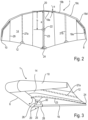
- FIG. 1 The use of a wing rig 1 according to the invention for driving a foil board 2 is shown.
- a surfer 4 holds the wing rig 1 only with his hands and adjusts it in relation to the wind depending on the desired Direction of travel (upwind, beam reach, downwind) or the lift to be adjusted, for example when jumping or adjusting the altitude.
- the wing rig 1 has an inflatable leading edge 6, which in plan view (from above into the Figures 1 and 2 ) is approximately arched, preferably approximately delta-, C- or U-shaped and extends with its tips 8, 10 up to a rear edge 12 of a sailcloth 14 of the wing rig 1.
- this sailcloth 14 is supported on the one hand by the front edge 6 and on the other hand by a boom 16 explained in more detail below (see Figure 3 ) is stretched out.
- the surfer 4 holds the wing rig 1 only by the boom 16, which is pointing downwards (view from Figure 1 ).
- the boom 16 is preferably provided with a casing that simplifies/optimizes gripping and holding.
- the front edge 6 is protruding both in plan view ( Figure 2 ) as well as in a front view - seen in the direction of flow - (see Figure 4 ) V-shaped, with the V/U extending upwards in the front view, ie, away from the surfer.
- the rear edge 12 and thus the entire canopy surface 14 is V- (or U-) shaped in the front view.
- Figure 2 shows a top view of the wing rig 1 according to Figure 1 .
- the leading edge 6 which is approximately arched or delta-shaped, in the broadest sense approximately U-shaped or C-shaped, and which extends to the trailing edge 12 of the sailcloth 14.
- the leading edge 6 is formed in the manner of a kite by a front tube in which a bladder is accommodated, which is inflated via a valve, the pressure being selected such that the structure of the wing rig 1 is guaranteed even at high wind strengths and speeds.
- the leading edge 6 is formed by a plurality of tube segments 18a, 18b, 18c, 18d, 18e (for the sake of simplicity, only one half of the trailing edge 12 is provided with reference numerals), the angle of attack ⁇ of which to the horizontal in Figure 2 (ie, for example, to a connecting line between the two end sections 8, 10) from a vertex 20 to the end sections 8, 10.
- This angle of attack ⁇ is shown as an example in the tube segment 18a.
- the reference number 22 indicates the The centre of gravity of the area (centre of the sailcloth) is marked. This centre of gravity 22 is offset from the apex 20 by at least 40 percent of the distance between the apex 20 and the corresponding apex 24 of the trailing edge 12.
- the distance between the apex 20, 24 is in Figure 2 marked with the reference symbol a. Accordingly, the distance b between the vertex 20 and the centroid 22 is at least 40 percent of the distance a.
- This area centre of gravity 22 is selected such that the surfer 4 can optimally grasp the boom 16, which will be explained in more detail below, and thus support the acting wind forces in order to, for example, sail an optimal upwind course.
- a central center sail batten 23 and two sail battens 27a, 27b offset towards the end sections 8, 10 are provided, which extend between the front edge 4 and the rear edge 12 and are inserted into corresponding sail batten pockets of the sailcloth 14.
- This insertion takes place in a manner known per se with a certain pre-tension, which is selected according to the desired profile or can also be changed in order to be able to adapt the profile to different wind strengths.
- the reference number 29 in Figure 2 Seams of the sailcloth 14 are also shown, which is made up of several panels. It may also be sufficient to design the panels in such a way that they are only sewn in the area of the sail battens or run continuously from tip 8 to tip 10.
- the boom 16 and the center batten 23 are thus in the same vertical plane, which in Figure 2 perpendicular to the plane of the drawing and in Figure 3 is in the plane of the drawing.
- the space between the boom and the sail batten 23 / sailcloth 14 is thus free, so that the surfer can freely choose his grip position depending on the maneuver/course.
- the front edge 6 is also perpendicular to the plane of the drawing in Figure 2 profiled. Specifically, the front edge 6 is V-shaped from the apex 20 to the end sections 8, 10, whereby the V (also called opening angle ⁇ ) - as in Figure 1 shown - upwards, ie, away from the boom 16.
- This V-profile is also formed accordingly in the area of the canvas 14. This is achieved, among other things, by the boom 16 reaching the apex 24 in the illustration according to Figure 3 downwards, ie, away from the end sections 8, 10, thus forming the V-shape which is determined by the opening angle ⁇ .
- the structure of the wing rig 1 is designed such that this opening angle ⁇ is reduced when exposed to the flow, since the end sections 8, 10 deflect upwards (away from the surfer 4) due to the load.
- the boom 16 thereby acts on the area of the apex 20 of the leading edge 6 which is spaced apart from the sailcloth 14 (at the bottom).
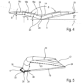
- the V-shape is particularly evident in the front view according to Figure 4 visible.
- the front edge 6 formed by the tube is arranged facing the viewer.
- the canvas 14 is accordingly V-shaped.
- the angle of inclination ⁇ of the leading edge 6 in the area of the apex is a maximum of 20°.
- this angle of inclination ⁇ i.e. the angle between the horizontal (parallel to the connecting line of the end sections 8, 10) and the tube segment 18a, is approximately 20°, for example.
- the next tube segment 18b is then set somewhat flatter, so that the angle is, for example, 15°.
- the angle of inclination of the following segments 18c, 18d, 18e is then again flatter, whereby the angle of inclination ⁇ in the area of the segment 18c can be, for example, 5°.
- the "average" angle of inclination ⁇ seen over the entire wing rig 1 is, for example, 10°, so that the "average" opening angle is then approximately 160°.
- the boom 16 is designed without braces - this is a significant difference to the complex constructions described at the beginning, in which the boom is designed with a large number of transverse and diagonal braces.
- the boom 16 can be detachably attached to the apex 20 of the front edge 6 via a holder 25.
- the holder 25 has a support bracket 26 which is designed to correspond to the outer contour of the apex 20 and surrounds it in sections. This surround is carried out in such a way that, in the event of comparatively high wind pressure, rotation of the tube, i.e. of the tube segments 18a forming the apex 20 in the direction of the arrow and thus twisting of the profile is reliably prevented.
- the support bracket 26 is then followed in the direction of the boom 16 by a holder 28 into which the boom 16 is inserted.
- the end sections of the support bracket 26 and the holder 28 are connected via an arched handle 30, which makes it easier for the surfer 4 to handle the wing rig 1 before and after use.
- the wing rig 1 can be held by the handle 30 when not in use in order to let it blow away in the wind.
- the holder 25 and the boom 16 are preferably made of a light material, for example aluminum, fiber-reinforced plastic, carbon fiber materials or other high-strength lightweight materials. Due to the simple structure of the boom 16, this has an insignificant influence on the overall weight of the wing rig 1.
- Figure 5 shows a side view of a variant of the previously described embodiment of a wing rig 1.
- the view corresponds approximately to that of Figure 3 .
- the apex 24 of the rear edge 12 is pushed downwards by the tree 16 (view from Figure 5
- the bracket 25 of the tree 16 has a receptacle 28 into which the tree 16 is inserted or which is connected to the tree 16 in some other way.
- the apex 20 is supported according to Figure 6 on the top of the holder 28.
- a lightweight, approximately U-shaped handle 32 extends away from the holder 28, the end section of which engages the apex 20 formed by the tube segments 18a at a distance from the support of the apex 20 on the holder 28, i.e. offset towards the canvas 14.
- the spacing of the support of the apex 20 on the holder 28 on the one hand and on the end section 34 of the handle 32 on the other hand also prevents the above-described rotation of the front edge 6 (front tube).
- the U-structure of the handle 32 allows the wing rig 1 to be easily held for blowing out.
- the handle 32 is designed as a framework structure.
- the connection of the receptacle 28 and the end section 34 to the apex can be formed via suitable fixing elements on the tube segments 18a. These fixing elements are preferably designed such that the handle 30 is detachably connected to the front edge 6 (front tube).
- the handle 32 which is more or less integrated into the tree structure, this can also be designed as a loop on the inflow side of the leading edge 6, so that the surfer can let the wing rig 1 blow out while holding it in his hand while surfing, for example.
- Figure 7 shows an embodiment in which the holder 25 is designed as a flat body which is designed to encompass the rear edge 6 or the tube segments 18a in sections.
- This flat holder can be designed as a molded body, for example.
- the holder 25 is made of canvas that is connected to the apex 20 of the front edge 6 and is stabilized by suitable stiffening elements if necessary.
- the boom 16 can then be inserted into this holder 25.
- the holder 25 is designed in such a way that rotation of the tube (front edge 6) in the direction of the arrow is prevented by the support by the boom 16.
- the front tube is designed with a continuous bladder, as explained.
- a separate bladder is used for each half of the wing rig, whereby between these two bladders as shown in Figure 8 a support channel 36 remains, into which the boom 16 is inserted.
- This support channel 36 can, for example, be formed by a piece of pipe which passes diametrically through the front tube.
- This support channel 36 is formed between the two bladders of the two wing rig halves (left, right).
- a bearing ring 40 is formed on an outer shell 38 of the front tube (front edge 6), which runs as an extension of the support channel 36 and through which the boom 16 passes.
- This bearing ring 40 absorbs the compression forces and is designed in a similar way to the support rings of the commonly used kite valves.
- a similar support ring 42 is provided opposite the bearing ring 40 on the inside of the outer shell 38, on which the Figure 8 left end section of the boom 16 is supported.
- the tubular support channel 36 is connected to the bearing ring 40 on the one hand and the support ring 42 on the other hand, so that the boom 16 is reliably fixed in position.
- Such a solution has the advantage that the bearing rings 40 and the support rings 42 can be used for practically any front tube diameter - only the length of the support channel 36 has to be adjusted.
- the boom 16 is very stably supported, so that the holding forces introduced by the surfer 4 and also the compression forces transmitted by the front tube are reliably absorbed without the boom 16 being excessively deformed.
- the support channel 36 and the rings 40, 42 are preferably designed as plastic injection molded parts.
- the sailcloth 14 can be stabilized using sail battens or the like. These sail battens can be conical or profiled in order to optimize the flow profile of the sailcloth 14.
- the leading edge 16 can also be stiffened using suitable stiffening elements so that the wing rig 1 maintains the aerodynamically optimized shape shown even under high loads.
- These sail battens or stiffening elements can also be designed as carbon fiber tubes or the like.
- the sail battens are profiled in such a way that they are first adapted to the diameter of the front edge 6 (front tube) and then support the sailcloth 14.
- sail battens can be inserted into the sailcloth 14 from the rear edge 12.
- wing rig 1 In order to prevent the wing rig 1 from drifting away in the event of a fall, it is connected to the surfer 4, in particular to his arm, via a safety leash 44.
- a hand-supported wing rig which is preferably designed with an inflatable leading edge, which is designed to widen upwards (away from the surfer) in the direction of flow in an approximately V-shape.
Landscapes
- Engineering & Computer Science (AREA)
- Chemical & Material Sciences (AREA)
- Combustion & Propulsion (AREA)
- Mechanical Engineering (AREA)
- Ocean & Marine Engineering (AREA)
- Sustainable Energy (AREA)
- Life Sciences & Earth Sciences (AREA)
- Sustainable Development (AREA)
- Manufacturing & Machinery (AREA)
- Toys (AREA)
- Wind Motors (AREA)
- Structures Of Non-Positive Displacement Pumps (AREA)
- Transition And Organic Metals Composition Catalysts For Addition Polymerization (AREA)
- Executing Machine-Instructions (AREA)
- Pyrane Compounds (AREA)
- Tents Or Canopies (AREA)
Abstract
Offenbart ist ein handgestütztes Flügelrigg, das vorzugsweise mit einer aufblasbaren Vorderkante ausgeführt ist, wobei diese sich in Anströmrichtung etwa V-förmig nach oben (weg vom Surfer) erweiternd ausgeführt ist.

Description
Die Erfindung betrifft ein handgestütztes Flügelrigg für windkraftgetriebene Sportarten, beispielsweise Foilsurfen (Wingfoil), gemäß dem Oberbegriff des Patentanspruchs 1.The invention relates to a hand-supported wing rig for wind-powered sports, for example foil surfing (wing foil), according to the preamble of
Ein derartiges Flügelrigg wird unter dem Namen "Slingwing" im Internet beschrieben. Es handelt sich dabei im Prinzip um einen Kite mit einer Vorderkante und einer einzigen Strut, die aufblasbar (inflatable) ausgeführt sind. An der mittigen Strut und an der Vorderkante sind jeweils Halteschlaufen ausgebildet, über die der Nutzer das inflatable Flügelrigg während der Nutzung, beispielsweise beim Foilen oder beim Eisskaten oder beim Skifahren hält.Such a wing rig is described on the Internet under the name "Slingwing". It is essentially a kite with a leading edge and a single strut, which are designed to be inflatable. There are holding loops on the central strut and on the leading edge, which the user uses to hold the inflatable wing rig during use, for example when foiling, ice skating or skiing.
Dieses an die Aerodynamik von Kites angepasste inflatable Flügelrigg wird während der Nutzung, insbesondere bei den beim Foilen erreichten hohen Geschwindigkeiten stark deformiert, und somit die Aerodynamik verschlechtert.This inflatable wing rig, which is adapted to the aerodynamics of kites, is severely deformed during use, especially at the high speeds reached during foiling, thus worsening the aerodynamics.
In der
Ein Nachteil dieser Lösung ist, dass durch den komplexen Aufbau des Baums und der Vorderkante das Gesamtgewicht des Flügelriggs sehr hoch ist, so dass eine Nutzung beim Wassersport nur mit entsprechenden Auftriebskörpern möglich ist. Ein weiterer Nachteil besteht darin, dass der Auf- und Abbau des Flügelriggs aufgrund der komplexen Rohrstruktur viel Zeit in Anspruch nimmt. Diese harte Rohrstruktur der Vorderkante und des Baums bringt auch eine erhebliche Verletzungsgefahr des Nutzers bei einem Schleudersturz mit sich.A disadvantage of this solution is that the total weight of the wing rig is very high due to the complex structure of the boom and the leading edge, so that use in water sports is only possible with appropriate buoyancy bodies. Another disadvantage is that the assembly and disassembly of the wing rig is difficult due to the complex tube structure takes a lot of time. This hard tube structure of the front edge and the boom also poses a significant risk of injury to the user in the event of a catastrophic fall.
Ein ähnliches starres Flügelrigg ist in der
In der Druckschrift
In dem Dokument
Aus der
Die
Die
Demgegenüber liegt der Erfindung die Aufgabe zugrunde, ein handgestütztes Flügelrigg zu schaffen, das einen einfachen Aufbau ermöglicht und auch bei hohen Fahrgeschwindigkeiten ein aerodynamisch optimiertes Profil beibehält.In contrast, the invention is based on the object of creating a hand-supported wing rig that allows for simple construction and maintains an aerodynamically optimized profile even at high speeds.
Diese Aufgabe wird durch ein handgestütztes Flügelrigg mit den Merkmalen des Patentanspruchs 1 gelöst.This object is achieved by a hand-supported wing rig having the features of
Vorteilhafte Weiterbildungen der Erfindung sind Gegenstand der Unteransprüche.Advantageous developments of the invention are the subject of the subclaims.
Das erfindungsgemäße handgestützte Flügelrigg ist für windkraftgetriebene Sportarten, beispielsweise für das Foilsurfen und die damit einhergehenden hohen Geschwindigkeiten geeignet. Das Flügelrigg hat eine, inflatable Vorderkante, von der sich ein Baum erstreckt, wobei die Vorderkante und der Baum ein Segeltuch aufspannen. Das Flügelrigg wird während der Nutzung insbesondere am Baum gehalten. Die Vorderkante ist von einer Anbindung des Baums weg zum Achterliek (Hinterkante) des Segeltuchs hin in einer Draufsicht etwa bogenförmig, deltaförmig, U- oder C-förmig gekrümmt ausgeführt. Die Vorderkante ist des Weiteren im nicht angeströmten oder unbelasteten Zustand in einer in Anströmrichtung gesehenen Frontansicht etwa V-förmig ausgebildet, wobei dieses Profil zum Baum hin konvergiert. Mit anderen Worten gesagt, das Profil öffnet sich bei der Nutzung nach oben, weg vom Fahrer. Es zeigte sich überraschender Weise, dass sich durch eine derartige ausgeprägte V- oder U-Profilierung und die bogenförmige, deltaförmige oder U- bzw. C-förmige Ausgestaltung der Vorderkante (in einer Draufsicht gesehen) auch bei hohen Wind- und Fahrgeschwindigkeiten ein aerodynamisch optimiertes Profil einstellt, das sich zum einen bei Böen selbsttätig öffnet und somit den resultierenden, vom Nutzer abzustützenden Druck verringert und zum anderen auch bei den hohen Fahrgeschwindigkeiten einen geringen aerodynamischen Widerstand erzeugt. Durch entsprechende Anstellung des Flügelriggs kann dabei in Abhängigkeit von der Windeinfallrichtung eine maximale Fahrgeschwindigkeit oder aber auch ein maximaler Auftrieb für Sprünge oder dergleichen generiert werden.The hand-supported wing rig according to the invention is suitable for wind-powered sports, for example for foil surfing and the high speeds associated with it. The wing rig has an inflatable front edge from which a boom extends, with the front edge and the boom stretching a sailcloth. The wing rig is held in particular by the boom during use. The front edge is curved in a plan view from a connection of the boom away to the leech (trailing edge) of the sailcloth in an approximately arched, delta-shaped, U-shaped or C-shaped manner. Furthermore, the front edge is approximately V-shaped in a front view viewed in the direction of flow when not exposed to airflow or unloaded, with this profile converging towards the boom. In other words, the profile opens upwards during use, away from the rider. Surprisingly, it was found that such a pronounced V or U profile and the arched, delta-shaped or U or C-shaped design of the leading edge (seen from above) creates an aerodynamically optimized profile even at high wind and speeds, which opens automatically in gusts and thus reduces the resulting pressure that the user has to support, and also generates low aerodynamic drag even at high speeds. By adjusting the wing rig accordingly, a maximum speed or maximum lift for jumps or the like can be generated depending on the direction of the wind.
Der Baum ist vorzugsweise als starres, nicht inflatable Bauteil ausgebildet. Unter dem Begriff "starres Bauteil" wird dabei eine aus einem weitgehend formsteifen Material ausgebildete Struktur verstanden, diese kann jedoch ohne weiteres zerlegbar oder aber auch teleskopierbar ausgeführt sein. Der Baum ist so ausgebildet, dass ein Halten des Flügelriggs während der Nutzung vereinfacht ist.The boom is preferably designed as a rigid, non-inflatable component. The term "rigid component" refers to a structure made of a largely dimensionally stable material, but this can easily be dismantled or made telescopic. The boom is designed in such a way that it is easier to hold the wing rig during use.
Der Baum ist vorzugsweise mit einer den Griffschluss/Reibschluss verbessernden Ummantelung ausgeführt.The tree is preferably designed with a sheath that improves the grip/friction.
Bei einem besonders bevorzugten Ausführungsbeispiel verläuft das etwa V-förmige Profil von der Vorderkante weg hin zur Hinterkante des Segeltuchs. D. h., das gesamte Flügelriggprofil ist in der Frontansicht (in Anströmrichtung gesehen) sich nach oben öffnend profiliert.In a particularly preferred embodiment, the approximately V-shaped profile runs from the leading edge to the trailing edge of the sailcloth. This means that the entire wing rigging profile is profiled so that it opens upwards when viewed from the front (in the direction of flow).
Der Wirkungsgrad des Flügelriggs wird weiter verbessert, wenn der V-Winkel im Anbindungsbereich des Baums maximal ist und zu den Endabschnitten hin abnimmt. Dabei wird es bevorzugt, wenn der Neigungswinkel zur Horizontalen (Parallele zur Verbindungslinie durch die Endabschnitte) im Scheitelbereich zwischen 10° und 30°, vorzugsweise mehr als 15°, besonders bevorzugt etwa 20° beträgt. Dabei wird unter dem "Neigungswinkel" derjenige Winkel verstanden, den der jeweilige Bereich der Vorderkante bei einer Positionierung des Flügelriggs parallel zur Wasseroberfläche/Nutzoberfläche, d. h. zur Horizontalen einnimmt. Der Öffnungswinkel zwischen den zueinander angestellten/geneigten Leading-Edge-Bereichen entspricht dann der Differenz zwischen 180° und dem Zweifachen des Neigungswinkels (Ergänzungswinkel zu 180°). Die Hinterkante (Achterliek) ist mit einem entsprechenden Profilwinkel ausgeführt.The efficiency of the wing rig is further improved when the V-angle is maximum in the boom connection area and decreases towards the end sections. It is preferred if the angle of inclination to the horizontal (parallel to the connecting line through the end sections) in the apex area is between 10° and 30°, preferably more than 15°, particularly preferably around 20°. The "angle of inclination" is understood to mean the angle that the respective area of the leading edge takes when the wing rig is positioned parallel to the water surface/usable surface, i.e. to the horizontal. The opening angle between the leading edge areas that are set/inclined towards each other then corresponds to the difference between 180° and twice the angle of inclination (supplementary angle to 180°). The trailing edge (leech) is designed with a corresponding profile angle.
Die Aerodynamik ist weiter verbessert, wenn der Neigungswinkel im Tipbereich zwischen 0° bis 20°, vorzugsweise mehr als 1°, vorzugsweise etwa 5° beträgt.The aerodynamics are further improved if the inclination angle in the tip area is between 0° and 20°, preferably more than 1°, preferably about 5°.
Das Flügelrigg ist bei einer Variante der Erfindung so ausgeführt, dass der mittlere Neigungswinkel, d. h., der Winkel vom Scheitel der Vorderkante bis zum jeweiligen Endabschnitt 5° bis 20°, vorzugsweise etwa 10° beträgt.In a variant of the invention, the wing rig is designed such that the average angle of inclination, i.e. the angle from the apex of the leading edge to the respective end section, is 5° to 20°, preferably about 10°.
Zur Anpassung an mehrere Flügelrigg-Größen kann der Baum teleskopierbar oder aus mehreren auswechselbaren Teilstücken bestehend ausgebildet werden.To accommodate multiple wing rig sizes, the boom can be telescopic or made up of several interchangeable sections.
Der vorrichtungstechnische Aufwand ist besonders gering, wenn der Baum mittels einer Halterung auswechselbar an der Vorderkante und der Hinterkante befestigt ist. Auf diese Weise kann ein einziger Baum für mehrere Flügelriggs verwendet werden.The technical effort required is particularly low if the boom is attached to the leading edge and the trailing edge using a bracket. In this way, a single boom can be used for several wing rigs.
Zur Minimierung des Gewichtes ist es vorteilhaft, den Baum rohrförmig auszubilden.To minimize weight, it is advantageous to make the tree tubular.
Die Flugstabilität des Flügelriggs wird weiter verbessert, wenn die Halterung des Baums derart ausgebildet ist, dass sie eine Rotation der Vorderkante um ihre Längsachse behindert.The flight stability of the wing rig is further improved if the boom mount is designed in such a way that it prevents rotation of the leading edge around its longitudinal axis.
Dabei wird es besonders bevorzugt, wenn die Halterung die Vorderkante abschnittsweise umgreift und somit eine Rotation unterbindet.It is particularly preferred if the holder encompasses the front edge in sections and thus prevents rotation.
Bei einer alternativen Lösung kann die Halterung auch die Vorderkante durchsetzen. Bei einer derartigen Ausgestaltung müssen dann an der Vorderkante entsprechende Aufnahmen für die Halterung bzw. den Baum ausgebildet sein. Des Weiteren sollte ein Kanal vorgesehen werden, in den die Halterung oder der Baum eingesetzt werden kann.In an alternative solution, the bracket can also pass through the front edge. With such a design, appropriate receptacles for the bracket or the boom must be formed on the front edge. Furthermore, a channel should be provided into which the bracket or the boom can be inserted.
Bei einer besonders bevorzugten Variante des Flügelriggs ist der Baum unverstrebt ausgeführt. Eine derartige Lösung ist zum einen gewichtsoptimiert und ermöglicht es zum anderen, dass der Nutzer den Baum und somit das Flügelrigg in Abhängigkeit vom jeweiligen Fahrmanöver und den Umgebungsbedingungen variabel halten kann.In a particularly preferred variant of the wing rig, the boom is designed without braces. This type of solution is weight-optimized and also allows the user to hold the boom and thus the wing rig variably depending on the respective driving maneuver and the environmental conditions.
Erfindungsgemäß ist der Flächenschwerpunkt (Zentrum des Segeltuchs) zumindest mehr als 40 Prozent des Abstandes zwischen dem Scheitel der Vorderkante und der Hinterkante (Achterliek) von der Vorderkante entfernt.According to the invention, the centre of gravity (centre of the sailcloth) is at least more than 40 percent of the distance between the apex of the leading edge and the trailing edge (leech) from the leading edge.
Zur weiteren Optimierung des Anströmprofils kann die Vorderkante und/oder das Segeltuch mittels Versteifungselementen, beispielsweise Segellatten versteift sein.To further optimize the flow profile, the leading edge and/or the sailcloth can be stiffened by means of stiffening elements, such as sail battens.
Diese Segellatten können ihrerseits zur Profilierung des Flügelprofils gekrümmt und/oder verjüngt sein.These sail battens can in turn be curved and/or tapered to shape the wing profile.
Bei einem besonders bevorzugten Ausführungsbeispiel erstreckt sich eine Segellatte von der Vorderkante zur Hinterkante, wobei diese Segellatte derart positioniert ist, dass sie mit dem Baum in einer Vertikalebene (bei horizontaler Ausrichtung des Flügelriggs) liegt.In a particularly preferred embodiment, a sail batten extends from the leading edge to the trailing edge, said sail batten being positioned such that it lies in a vertical plane with the boom (when the wing rig is aligned horizontally).
Zur Vereinfachung der Handhabung kann im Anbindungsbereich des Baums vorzugsweise an der Vorderkante ein Handgriff vorgesehen werden.To simplify handling, a handle can be provided in the connection area of the tree, preferably at the front edge.
Um bei einem Sturz das Trennen vom Nutzer zu verhindern, ist das Flügelrigg mit einer Safetyleash ausgeführt.To prevent separation from the user in the event of a fall, the wing rig is designed with a safety leash.
Die Halterung zur Anbindung des Baums an die Vorderkante kann beispielsweise durch ein Profilstück ausgebildet sein, das die Vorderkante abschnittsweise umgreift und über geeignete Befestigungsmittel an die Vorderkante angesetzt ist. Der Baum wird dann in das Profilstück eingesteckt oder in sonstiger Weise mit diesem verbunden.The bracket for connecting the boom to the front edge can, for example, be formed by a profile piece that surrounds the front edge in sections and is attached to the front edge using suitable fastening means. The boom is then inserted into the profile piece or connected to it in some other way.
Bei einer alternativen Lösung ist an der Vorderkante mittels Profilteilen oder Segeltuch eine Halterung für den Baum ausgebildet. Diese Profilteile umgreifen die Vorderkante wiederum abschnittsweise, so dass eine Rotation der Vorderkante während der Nutzung unterbunden ist.An alternative solution is to create a holder for the boom on the front edge using profile parts or canvas. These profile parts then enclose the front edge in sections, preventing the front edge from rotating during use.
Der Baum erstreckt sich vorzugsweise von der Vorderkante bis zur Hinterkante, ohne in den dazwischenliegenden Bereichen direkt oder fest mit dem Segeltuch verbunden zu sein, sodass praktisch die gesamte Baumlänge als Griffbereich zur Verfügung steht. Dadurch ist gewährleistet, dass das Halten des Flügelriggs bei jedweden Manövern in optimaler Weise nach den Vorlieben des Nutzers gewählt werden kann. Des Weiteren kann durch Verstellen der Baumlänge die Profiltiefe eingestellt werden.The boom preferably extends from the leading edge to the trailing edge without being directly or firmly connected to the sailcloth in the areas in between, so that practically the entire length of the boom is available as a grip area. This ensures that the wing rig can be held optimally according to the user's preferences during any maneuver. Furthermore, the profile depth can be adjusted by adjusting the boom length.
Die Struktur des Flügelriggs ist so ausgelegt, dass im angeströmten Zustand, das heißt bei der Nutzung des Flügelriggs, insbesondere der Öffnungswinkel im Bereich der Hinterkante verringert wird. Das heißt, der Neigungswinkel α der Trailing-Edge-Bereiche zur Horizontalen vergrößert sich bei der Nutzung. Dementsprechend kann sich auch die Profiltiefe im angeströmten Zustand vergrößern. Die Änderung des Öffnungswinkels kann dabei im Trailing-Edge-Bereich größer als im Leading-Edge-Bereich sein.The structure of the wing rig is designed in such a way that when exposed to airflow, i.e. when the wing rig is in use, the opening angle in the area of the trailing edge is reduced. This means that the angle of inclination α of the trailing edge areas to the horizontal increases during use. Accordingly, the profile depth can also increase when exposed to airflow. The change in the opening angle can be greater in the trailing edge area than in the leading edge area.
Der Baum ist vorzugsweise an dem von dem Segeltuch abgewandten Bereich am Scheitel der Vorderkante befestigt.The boom is preferably attached to the area facing away from the canvas at the apex of the leading edge.
Die Befestigung ist derart, dass ein seitliches Verschwenken/Anstellen des Flügelriggs durch Drehen des Baums um seine Längsachse möglich ist - dies wäre mit Schlaufen (Handles) nicht möglich, da diese nicht biegesteif sind und somit kein Drehmoment aufgebracht werden kann.The attachment is such that the wing rig can be swivelled/adjusted sideways by turning the boom around its longitudinal axis - this would not be possible with loops (handles) as these are not rigid and therefore no torque can be applied.
Bevorzugte Ausführungsbeispiele der Erfindung werden im Folgenden anhand schematischer Zeichnungen näher erläutert. Es zeigen:
-
Figur 1 -
Figur 2 eine Draufsicht auf einFlügelrigg gemäß Figur 1 ; -
Figur 3 eine Seitenansicht des Flügelriggs gemäßden Figuren 1 und2 ; -
Figur 4den Figuren 1 bis 3 ; -
Figur 5 eine Seitenansicht eines weiteren Ausführungsbeispiels eines Flügelriggs; -
Figur 6Figur 5 ; -
Figur 7 eine Teildarstellung eines dritten Ausführungsbeispiels eines Flügelriggs und -
Figur 8
-
Figure 1 a schematic diagram of a first embodiment of a wing rig used to drive a foil board; -
Figure 2 a plan view of a wing rig according toFigure 1 ; -
Figure 3 a side view of the wing rig according to theFigures 1 and2 ; -
Figure 4 a front view of a wing rig according to theFigures 1 to 3 ; -
Figure 5 a side view of another embodiment of a wing rig; -
Figure 6 a detailed representation of the wing rig according toFigure 5 ; -
Figure 7 a partial view of a third embodiment of a wing rig and -
Figure 8 a schematic representation of a fourth embodiment of a wing rig according to the invention.
In
Das Flügelrigg 1 hat eine aufblasbare Vorderkante 6, die in der Draufsicht (von oben her in den
Bei dem dargestellten Ausführungsbeispiel ist die Vorderkante 6 durch eine Vielzahl von Tubesegmenten 18a, 18b, 18c, 18d, 18e (der Einfachheit halber wird nur eine Hälfte der Hinterkante 12 mit Bezugszeichen versehen) ausgebildet, deren Anstellwinkel α zur Horizontalen in
Dieser Flächenschwerpunkt 22 ist so gewählt, dass der Surfer 4 den im Folgenden noch näher erläuterten Baum 16 in optimaler Weise ergreifen und so die einwirkenden Windkräfte abstützen kann, um beispielsweise einen optimalen Amwind-Kurs zu fahren.This area centre of
Zur Aussteifung des Flügelprofils sind eine mittlere Center-Segellatte 23 und zwei zu den Endabschnitten 8, 10 hin versetzte Segellatten 27a, 27b vorgesehen, die sich zwischen der Vorderkante 4 und der Hinterkante 12 erstrecken und in entsprechende Segellattentaschen des Segeltuchs 14 eingesetzt sind. Dieses Einsetzen erfolgt in an sich bekannter Weise mit einer gewissen Vorspannung, die entsprechend der gewünschten Profilierung gewählt ist oder auch veränderbar ist, um das Profil an unterschiedliche Windstärken anpassen zu können. Mit dem Bezugszeichen 29 sind in
In der Seitenansicht gemäß
Wie des Weiteren
Die V-Form ist besonders deutlich in der Vorderansicht gemäß
Bei allen beschriebenen Ausführungsbeispielen ist der Baum 16 unverstrebt ausgebildet - dies ist ein wesentlicher Unterschied zu den eingangs beschriebenen komplexen Konstruktionen, bei denen der Baum mit einer Vielzahl von Quer- und Schrägstreben ausgeführt ist. Bei der erfindungsgemäßen Lösung kann der Baum 16 über eine Halterung 25 lösbar am Scheitel 20 der Vorderkante 6 befestigt werden.In all the embodiments described, the
Beim dargestellten Ausführungsbeispiel hat die Halterung 25 eine Stützkonsole 26, die entsprechend der Außenkontur des Scheitels 20 ausgebildet ist und diesen abschnittsweise umgreift. Dieses Umgreifen erfolgt derart, dass bei vergleichsweise hohem Winddruck eine Rotation der Tube, d. h., der den Scheitel 20 ausbildenden Tubesegmente 18a in Pfeilrichtung und damit ein Verwinden des Profils zuverlässig verhindert wird.In the embodiment shown, the
An die Stützkonsole 26 schließt sich dann in Richtung des Baums 16 eine Aufnahme 28 an, in die der Baum 16 eingesteckt wird. Die Endabschnitte der Stützkonsole 26 und der Aufnahme 28 sind über einen bogenförmigen Handgriff 30 verbunden, der dem Surfer 4 das Handling des Flügelriggs 1 vor und nach der Nutzung erleichtert. So kann beispielsweise das Flügelrigg 1 bei Nichtnutzung am Handgriff 30 gehalten werden, um dieses im Wind auswehen zu lassen. Die Halterung 25 und der Baum 16 sind vorzugsweise aus einem leichten Material, beispielsweise aus Aluminium, faserverstärktem Kunststoff, Kohlefasermaterialien oder sonstigen hochfesten Leichtbaumaterialien ausgebildet. Aufgrund der einfachen Struktur des Baums 16 beeinflusst dieser das Gesamtgewicht des Flügelriggs 1 unwesentlich.The
Durch die U-Struktur des Haltegriffs 32 kann das Flügelrigg 1 auf einfache Weise zum Auswehen gehalten werden. Wie insbesondere in
Anstelle des mehr oder weniger in die Baumstruktur integrierter Handgriffs 30, Haltegriffs 32 kann dieser auch als Schlaufe an der Anströmseite der Vorderkante 6 ausgebildet werden, sodass der Surfer das Flügelrigg 1 beispielsweise beim Surfen in der Hand haltend auswehen lassen kann.Instead of the
Diese flächige Halterung kann beispielsweise als Formkörper ausgebildet sein. Bei einem besonders einfach ausgeführten Ausführungsbeispiel ist die Halterung 25 aus Segeltuch ausgebildet, das mit dem Scheitel 20 der Vorderkante 6 verbunden ist und ggf. durch geeignete Versteifungselemente stabilisiert wird. In diese Halterung 25 kann dann wiederum der Baum 16 eingesetzt werden. Auch bei diesem Ausführungsbeispiel ist die Halterung 25 so ausgelegt, dass eine Rotation der Tube (Vorderkante 6) in Pfeilrichtung durch die Abstützung mittels des Baums 16 verhindert wird.This flat holder can be designed as a molded body, for example. In a particularly simple embodiment, the
Bei den vorbeschriebenen Ausführungsbeispielen ist die Fronttube - wie erläutert - mit einer durchgehenden Bladder ausgeführt. Bei dem Beispiel gemäß
Ein ähnlicher Stützring 42 ist gegenüberliegend zum Lagerring 40 an der Innenseite der Außenhülle 38 vorgesehen, an dem der in
Eine derartige Lösung hat den Vorteil, dass die Lagerringe 40 und die Stützringe 42 praktisch für jedweden Fronttubedurchmesser verwendbar sind - es muss lediglich die Länge des Stützkanals 36 angepasst werden. Bei einer derartigen Lösung ist der Baum 16 sehr stabil abgestützt, so dass die vom Surfer 4 eingeleiteten Haltekräfte und auch die von der Fronttube übertragenen Kompressionskräfte zuverlässig aufgenommen werden, ohne dass der Baum 16 übermäßig verformt wird. Der Stützkanal 36 und die Ringe 40, 42 werden vorzugweise als Kunststoffspritzgussteile ausgeführt.Such a solution has the advantage that the bearing rings 40 and the support rings 42 can be used for practically any front tube diameter - only the length of the
Bei allen vorbeschriebenen Ausführungsbeispielen kann das Segeltuch 14 über Segellatten oder dergleichen stabilisiert werden. Diese Segellatten können konisch ausgebildet oder profiliert sein, um das Anströmprofil des Segeltuchs 14 zu optimieren. In entsprechender Weise kann auch die Vorderkante 16 über geeignete Versteifungselemente ausgesteift werden, so dass das Flügelrigg 1 die dargestellte aerodynamisch optimierte Form auch bei hohen Belastungen hält.In all of the above-described embodiments, the
Diese Segellatten oder Versteifungselemente können auch als Kohlefaserrohre oder dergleichen ausgebildet sein.These sail battens or stiffening elements can also be designed as carbon fiber tubes or the like.
Bei einem Ausführungsbeispiel sind die Segellatten derart profiliert, dass sie zunächst an den Durchmesser der Vorderkante 6 (Fronttube) angepasst sind und dann das Segeltuch 14 abstützen. Selbstverständlich können zusätzlich oder alternativ Segellatten von der Hinterkante 12 her in das Segeltuch 14 eingesetzt werden.In one embodiment, the sail battens are profiled in such a way that they are first adapted to the diameter of the front edge 6 (front tube) and then support the
Um im Falle eines Sturzes das Abtreiben des Flügelriggs 1 zu verhindern, ist dieses über eine Safety-Leash 44 mit dem Surfer 4, insbesondere mit dessen Arm verbunden.In order to prevent the
Offenbart ist ein handgestütztes Flügelrigg, das vorzugsweise mit einer aufblasbaren Vorderkante ausgeführt ist, wobei diese sich in Anströmrichtung etwa V-förmig nach oben (weg vom Surfer) erweiternd ausgeführt ist.Disclosed is a hand-supported wing rig, which is preferably designed with an inflatable leading edge, which is designed to widen upwards (away from the surfer) in the direction of flow in an approximately V-shape.
- 11
- Flügelriggwing rig
- 22
- Foilboardfoil board
- 44
- Surfersurfer
- 66
- Vorderkante / Fronttubeleading edge / front tube
- 88
- Endabschnittfinal section
- 1010
- Endabschnittfinal section
- 1212
- Hinterkantetrailing edge
- 1414
- Segeltuchcanvas
- 1616
- BaumTree
- 1818
- Tubesegmenttube segment
- 2020
- Scheitel der Vorderkanteapex of the leading edge
- 2222
- Flächenschwerpunktcentroid
- 2323
- Center-Segellattecenter batten
- 2424
- Scheitel der Hinterkanteapex of the trailing edge
- 2525
- Halterungbracket
- 2626
- Stützkonsolesupport bracket
- 2727
- Segellattesail batten
- 2828
- AufnahmeRecording
- 2929
- Nahtseam
- 3030
- Handgriffhandle
- 3232
- Haltegriffhandle
- 3434
- Endabschnittfinal section
- 3636
- Stützkanalsupport channel
- 3838
- Außenhülleouter shell
- 4040
- Lagerringbearing ring
- 4242
- Stützringsupport ring
- 4444
- Safety-Leashsafety leash
- αα
- Anstellwinkelangle of attack
- ββ
- Neigungswinkelangle of inclination
- γγ
- Neigungswinkel zu den Endabschnittenangle of inclination to the end sections
- δδ
- Öffnungswinkel (180°-2β)opening angle (180°-2β)
Claims (5)
dadurch gekennzeichnet, dass
characterized in that
Applications Claiming Priority (4)
| Application Number | Priority Date | Filing Date | Title |
|---|---|---|---|
| DE102019101656.8A DE102019101656B4 (en) | 2019-01-23 | 2019-01-23 | wing rig |
| EP20701589.2A EP3914510B2 (en) | 2019-01-23 | 2020-01-22 | Wing rig |
| EP23177722.8A EP4234389B1 (en) | 2019-01-23 | 2020-01-22 | Wing foil |
| PCT/EP2020/051463 WO2020152198A1 (en) | 2019-01-23 | 2020-01-22 | Wing rig |
Related Parent Applications (3)
| Application Number | Title | Priority Date | Filing Date |
|---|---|---|---|
| EP23177722.8A Division EP4234389B1 (en) | 2019-01-23 | 2020-01-22 | Wing foil |
| EP20701589.2A Division-Into EP3914510B2 (en) | 2019-01-23 | 2020-01-22 | Wing rig |
| EP20701589.2A Division EP3914510B2 (en) | 2019-01-23 | 2020-01-22 | Wing rig |
Publications (2)
| Publication Number | Publication Date |
|---|---|
| EP4470902A2 true EP4470902A2 (en) | 2024-12-04 |
| EP4470902A3 EP4470902A3 (en) | 2025-03-19 |
Family
ID=69187793
Family Applications (3)
| Application Number | Title | Priority Date | Filing Date |
|---|---|---|---|
| EP24208200.6A Pending EP4470902A3 (en) | 2019-01-23 | 2020-01-22 | Wing rig |
| EP20701589.2A Active EP3914510B2 (en) | 2019-01-23 | 2020-01-22 | Wing rig |
| EP23177722.8A Active EP4234389B1 (en) | 2019-01-23 | 2020-01-22 | Wing foil |
Family Applications After (2)
| Application Number | Title | Priority Date | Filing Date |
|---|---|---|---|
| EP20701589.2A Active EP3914510B2 (en) | 2019-01-23 | 2020-01-22 | Wing rig |
| EP23177722.8A Active EP4234389B1 (en) | 2019-01-23 | 2020-01-22 | Wing foil |
Country Status (5)
| Country | Link |
|---|---|
| US (1) | US11738840B2 (en) |
| EP (3) | EP4470902A3 (en) |
| DE (2) | DE102019101656B4 (en) |
| ES (1) | ES2952068T5 (en) |
| WO (1) | WO2020152198A1 (en) |
Families Citing this family (16)
| Publication number | Priority date | Publication date | Assignee | Title |
|---|---|---|---|---|
| DE102020122143A1 (en) | 2019-10-31 | 2021-05-06 | Boards & More Gmbh | Wing rig |
| DE102019129493A1 (en) | 2019-10-31 | 2021-05-06 | Boards & More Gmbh | Kite and wing rig |
| DE102020122145A1 (en) | 2019-10-31 | 2021-05-06 | Boards & More Gmbh | Wing rig |
| DE102021106993B4 (en) | 2020-08-17 | 2024-10-31 | Boards & More Gmbh | wing rig |
| DE202021101663U1 (en) | 2020-08-17 | 2021-06-22 | Boards & More Gmbh | Wing rig |
| EP4023546B1 (en) | 2020-12-29 | 2024-06-19 | Boards & More GmbH | Wing rig |
| FR3121657A1 (en) | 2021-04-12 | 2022-10-14 | F. One | Autonomous traction wing |
| EP4323271A1 (en) | 2021-04-12 | 2024-02-21 | F.One | Self-contained traction wing |
| DE102021125438A1 (en) | 2021-04-15 | 2022-10-20 | Boards & More Gmbh | wing rig |
| WO2022218959A1 (en) | 2021-04-15 | 2022-10-20 | Boards & More Gmbh | Wing foil and kite |
| US12157551B2 (en) * | 2021-10-27 | 2024-12-03 | Douglas A. Dockray | Power assisted devices for generating force for powering a user on a vehicle in kiteboarding, wing foiling, paddleboarding, and the like |
| DE102021214265A1 (en) | 2021-12-13 | 2023-06-15 | Boards & More Gmbh | wing |
| IT202200006818A1 (en) * | 2022-04-06 | 2023-10-06 | Zm Design S R L | INFLATABLE WING SAIL WITH AERODYNAMICALLY OPTIMIZED LEADING EDGE |
| FR3142746A1 (en) * | 2022-12-01 | 2024-06-07 | Roland LE BAIL | Free sail with particular geometry combining structure and grip |
| PL4400407T3 (en) * | 2023-01-12 | 2025-08-18 | Ozone Kites Ltd. | A wing sail |
| FR3155807A1 (en) | 2023-11-24 | 2025-05-30 | sylvain barrière | Retractable manually supported traction wing |
Citations (7)
| Publication number | Priority date | Publication date | Assignee | Title |
|---|---|---|---|---|
| DE3140685A1 (en) | 1981-10-13 | 1983-04-28 | James R. 90402 Santa Monica Calif. Drake | "HAND SAIL" |
| DE3406040A1 (en) | 1983-10-18 | 1985-08-22 | Otto Dr.med. 5000 Köln Jung | Dragon rig |
| US4563969A (en) | 1981-03-11 | 1986-01-14 | Le Bail Roland C | Sail having variable propelling and lifting effects |
| US4742977A (en) | 1986-11-03 | 1988-05-10 | Crowell Robert L | Wing structure with self-induced camber |
| GB2203113A (en) | 1987-03-16 | 1988-10-12 | Barry John Jacobson | An inflatable aerodynamic wing structure |
| WO1995005973A1 (en) | 1993-08-20 | 1995-03-02 | Oy Skywings Ab | Wing sail |
| US5448961A (en) | 1992-07-13 | 1995-09-12 | Ansteensen; Erik | User supported portable sail |
Family Cites Families (11)
| Publication number | Priority date | Publication date | Assignee | Title |
|---|---|---|---|---|
| US3487800A (en) * | 1968-03-27 | 1970-01-06 | Hoyle Schweitzer | Wind-propelled apparatus |
| US4533159A (en) * | 1984-04-27 | 1985-08-06 | Seidel John C | Wind propulsion apparatus |
| DE3421503A1 (en) * | 1984-06-08 | 1985-12-12 | Fritz 8200 Rosenheim Eib | Lightweight wing |
| EP0198065A1 (en) | 1984-10-17 | 1986-10-22 | CROWELL, Robert Lee | Pivot wing sailing/flying apparatus |
| DE19700293A1 (en) | 1997-01-08 | 1998-07-09 | Roger Jurriens | Sails for a vehicle that can be moved by wind power |
| EP1151918B1 (en) * | 2000-05-05 | 2003-11-19 | Gesuino Petretto | Hang glider |
| FR2811634B1 (en) * | 2000-07-12 | 2003-01-31 | Dominique Meignen | RIGID WING WITH INFLATABLE FRAME WITH TENSIONED MEMBRANE |
| FR2854373B1 (en) * | 2003-04-30 | 2006-05-05 | Salomon Sa | TRACTION WING IN DELTA CONFIGURATION |
| DE202007018167U1 (en) * | 2007-08-13 | 2008-07-10 | Boards & More Ag, Clarens | Surf or sail rigging and sails for such a rig |
| DE102015117708A1 (en) * | 2014-11-03 | 2016-05-04 | Boards & More Gmbh | Segelrigg |
| DE102016113858B4 (en) * | 2016-03-07 | 2018-03-29 | Boards & More Gmbh | kite |
-
2019
- 2019-01-23 DE DE102019101656.8A patent/DE102019101656B4/en active Active
-
2020
- 2020-01-22 US US17/425,168 patent/US11738840B2/en active Active
- 2020-01-22 EP EP24208200.6A patent/EP4470902A3/en active Pending
- 2020-01-22 DE DE212020000445.5U patent/DE212020000445U1/en active Active
- 2020-01-22 WO PCT/EP2020/051463 patent/WO2020152198A1/en not_active Ceased
- 2020-01-22 EP EP20701589.2A patent/EP3914510B2/en active Active
- 2020-01-22 EP EP23177722.8A patent/EP4234389B1/en active Active
- 2020-01-22 ES ES20701589T patent/ES2952068T5/en active Active
Patent Citations (7)
| Publication number | Priority date | Publication date | Assignee | Title |
|---|---|---|---|---|
| US4563969A (en) | 1981-03-11 | 1986-01-14 | Le Bail Roland C | Sail having variable propelling and lifting effects |
| DE3140685A1 (en) | 1981-10-13 | 1983-04-28 | James R. 90402 Santa Monica Calif. Drake | "HAND SAIL" |
| DE3406040A1 (en) | 1983-10-18 | 1985-08-22 | Otto Dr.med. 5000 Köln Jung | Dragon rig |
| US4742977A (en) | 1986-11-03 | 1988-05-10 | Crowell Robert L | Wing structure with self-induced camber |
| GB2203113A (en) | 1987-03-16 | 1988-10-12 | Barry John Jacobson | An inflatable aerodynamic wing structure |
| US5448961A (en) | 1992-07-13 | 1995-09-12 | Ansteensen; Erik | User supported portable sail |
| WO1995005973A1 (en) | 1993-08-20 | 1995-03-02 | Oy Skywings Ab | Wing sail |
Also Published As
| Publication number | Publication date |
|---|---|
| EP3914510A1 (en) | 2021-12-01 |
| EP4234389A2 (en) | 2023-08-30 |
| ES2952068T3 (en) | 2023-10-26 |
| EP3914510B2 (en) | 2025-04-16 |
| EP4234389B1 (en) | 2024-10-23 |
| US11738840B2 (en) | 2023-08-29 |
| ES2952068T5 (en) | 2025-06-26 |
| US20220119086A1 (en) | 2022-04-21 |
| EP4234389C0 (en) | 2024-10-23 |
| EP4470902A3 (en) | 2025-03-19 |
| DE102019101656B4 (en) | 2025-04-30 |
| EP4234389A3 (en) | 2023-11-08 |
| DE212020000445U1 (en) | 2021-04-06 |
| EP3914510B1 (en) | 2023-06-07 |
| DE102019101656A1 (en) | 2020-07-23 |
| WO2020152198A1 (en) | 2020-07-30 |
Similar Documents
| Publication | Publication Date | Title |
|---|---|---|
| EP4234389B1 (en) | Wing foil | |
| EP4051577B1 (en) | Wing rig | |
| EP3215418B1 (en) | Sailing rig | |
| EP3405386B1 (en) | Mast and corresponding rig, in particular for a surfboard | |
| EP4097001B1 (en) | Wing rig | |
| WO2021084036A1 (en) | Wing rig | |
| DE102021106993B4 (en) | wing rig | |
| EP0076954A1 (en) | Hand-held sail | |
| EP4023546B1 (en) | Wing rig | |
| DE202015102731U1 (en) | Segelrigg | |
| DE102021112724A1 (en) | wing rig | |
| EP4323272A1 (en) | Wing foil and kite | |
| DE29501822U1 (en) | Drachenrigg | |
| WO1985000333A1 (en) | Sail rig | |
| EP1238907B1 (en) | Steerable kite | |
| DE3104750A1 (en) | Rig in wing form for vessels furnished with sails | |
| DE102004029432B4 (en) | Device for handling sails and sail guidance devices on a vehicle powered by wind power | |
| DE202007018167U1 (en) | Surf or sail rigging and sails for such a rig | |
| DE102022134613A1 (en) | WING FOR WIND POWERED SPORTS | |
| DE102015102062A1 (en) | Segelrigg | |
| DE102021214265A1 (en) | wing | |
| EP4448381A1 (en) | Wing comprising an at least partially inflatable support structure for sports using wind-powered movement | |
| DE3231764A1 (en) | Wing rig | |
| DE3151067A1 (en) | Rig for a sailboard | |
| DE102015118216A1 (en) | Segelrigg |
Legal Events
| Date | Code | Title | Description |
|---|---|---|---|
| PUAI | Public reference made under article 153(3) epc to a published international application that has entered the european phase |
Free format text: ORIGINAL CODE: 0009012 |
|
| STAA | Information on the status of an ep patent application or granted ep patent |
Free format text: STATUS: THE APPLICATION HAS BEEN PUBLISHED |
|
| AC | Divisional application: reference to earlier application |
Ref document number: 3914510 Country of ref document: EP Kind code of ref document: P Ref document number: 4234389 Country of ref document: EP Kind code of ref document: P |
|
| AK | Designated contracting states |
Kind code of ref document: A2 Designated state(s): AL AT BE BG CH CY CZ DE DK EE ES FI FR GB GR HR HU IE IS IT LI LT LU LV MC MK MT NL NO PL PT RO RS SE SI SK SM TR |
|
| PUAL | Search report despatched |
Free format text: ORIGINAL CODE: 0009013 |
|
| AK | Designated contracting states |
Kind code of ref document: A3 Designated state(s): AL AT BE BG CH CY CZ DE DK EE ES FI FR GB GR HR HU IE IS IT LI LT LU LV MC MK MT NL NO PL PT RO RS SE SI SK SM TR |
|
| RIC1 | Information provided on ipc code assigned before grant |
Ipc: B63H 8/10 20200101AFI20250213BHEP |
|
| STAA | Information on the status of an ep patent application or granted ep patent |
Free format text: STATUS: REQUEST FOR EXAMINATION WAS MADE |
|
| 17P | Request for examination filed |
Effective date: 20250423 |