EP4234389A2 - Wing rig - Google Patents
Wing rig Download PDFInfo
- Publication number
- EP4234389A2 EP4234389A2 EP23177722.8A EP23177722A EP4234389A2 EP 4234389 A2 EP4234389 A2 EP 4234389A2 EP 23177722 A EP23177722 A EP 23177722A EP 4234389 A2 EP4234389 A2 EP 4234389A2
- Authority
- EP
- European Patent Office
- Prior art keywords
- front tube
- wing
- foil
- leading edge
- angle
- Prior art date
- Legal status (The legal status is an assumption and is not a legal conclusion. Google has not performed a legal analysis and makes no representation as to the accuracy of the status listed.)
- Pending
Links
- JTJMJGYZQZDUJJ-UHFFFAOYSA-N phencyclidine Chemical compound C1CCCCN1C1(C=2C=CC=CC=2)CCCCC1 JTJMJGYZQZDUJJ-UHFFFAOYSA-N 0.000 claims abstract description 17
- 239000011888 foil Substances 0.000 claims description 25
- XLYOFNOQVPJJNP-UHFFFAOYSA-N water Substances O XLYOFNOQVPJJNP-UHFFFAOYSA-N 0.000 claims description 5
- 230000007423 decrease Effects 0.000 claims description 4
- 238000007664 blowing Methods 0.000 claims description 2
- 239000000243 solution Substances 0.000 description 9
- 241000545744 Hirudinea Species 0.000 description 3
- 239000000463 material Substances 0.000 description 3
- 229920000049 Carbon (fiber) Polymers 0.000 description 2
- 208000027418 Wounds and injury Diseases 0.000 description 2
- 239000004917 carbon fiber Substances 0.000 description 2
- 230000006835 compression Effects 0.000 description 2
- 238000007906 compression Methods 0.000 description 2
- 238000010276 construction Methods 0.000 description 2
- 230000006378 damage Effects 0.000 description 2
- 208000014674 injury Diseases 0.000 description 2
- VNWKTOKETHGBQD-UHFFFAOYSA-N methane Chemical compound C VNWKTOKETHGBQD-UHFFFAOYSA-N 0.000 description 2
- 229920002430 Fibre-reinforced plastic Polymers 0.000 description 1
- XAGFODPZIPBFFR-UHFFFAOYSA-N aluminium Chemical compound [Al] XAGFODPZIPBFFR-UHFFFAOYSA-N 0.000 description 1
- 229910052782 aluminium Inorganic materials 0.000 description 1
- UQMRAFJOBWOFNS-UHFFFAOYSA-N butyl 2-(2,4-dichlorophenoxy)acetate Chemical group CCCCOC(=O)COC1=CC=C(Cl)C=C1Cl UQMRAFJOBWOFNS-UHFFFAOYSA-N 0.000 description 1
- 230000001419 dependent effect Effects 0.000 description 1
- 238000011161 development Methods 0.000 description 1
- 230000018109 developmental process Effects 0.000 description 1
- 238000011982 device technology Methods 0.000 description 1
- 238000010586 diagram Methods 0.000 description 1
- 230000007613 environmental effect Effects 0.000 description 1
- 239000011151 fibre-reinforced plastic Substances 0.000 description 1
- 230000001771 impaired effect Effects 0.000 description 1
- 238000002347 injection Methods 0.000 description 1
- 239000007924 injection Substances 0.000 description 1
- 238000003780 insertion Methods 0.000 description 1
- 230000037431 insertion Effects 0.000 description 1
- 230000009191 jumping Effects 0.000 description 1
- 239000003562 lightweight material Substances 0.000 description 1
- 239000004033 plastic Substances 0.000 description 1
- 229920003023 plastic Polymers 0.000 description 1
- 238000000926 separation method Methods 0.000 description 1
- 230000006641 stabilisation Effects 0.000 description 1
- 238000011105 stabilization Methods 0.000 description 1
Images
Classifications
-
- B—PERFORMING OPERATIONS; TRANSPORTING
- B63—SHIPS OR OTHER WATERBORNE VESSELS; RELATED EQUIPMENT
- B63H—MARINE PROPULSION OR STEERING
- B63H9/00—Marine propulsion provided directly by wind power
- B63H9/04—Marine propulsion provided directly by wind power using sails or like wind-catching surfaces
- B63H9/06—Types of sail; Constructional features of sails; Arrangements thereof on vessels
- B63H9/067—Sails characterised by their construction or manufacturing process
-
- B—PERFORMING OPERATIONS; TRANSPORTING
- B63—SHIPS OR OTHER WATERBORNE VESSELS; RELATED EQUIPMENT
- B63H—MARINE PROPULSION OR STEERING
- B63H8/00—Sail or rigging arrangements specially adapted for water sports boards, e.g. for windsurfing or kitesurfing
- B63H8/10—Kite-sails; Kite-wings; Control thereof; Safety means therefor
- B63H8/16—Control arrangements, e.g. control bars or control lines
Definitions
- the invention relates to a hand-supported wing rig for wind-powered sports, such as foil surfing, according to the preamble of patent claim 1.
- Such a wing rig is described under the name "Slingwing” on the Internet. It is basically a kite with a leading edge and a single strut that are inflatable. On the central strut and on the leading edge there are holding loops, which the user uses to hold the inflatable wing rig during use, for example when foiling or ice skating or skiing.
- This inflatable wing rig which is adapted to the aerodynamics of kites, is severely deformed during use, especially at the high speeds achieved when foiling, and the aerodynamics are thus impaired.
- a rigid wing rig in which the leading edge and a boom are formed by a complex tubular construction that spans a canvas (canopy).
- the leading edge is curved in an arc shape as seen in a plan view.
- the tree is supported by a multitude of struts at the leading edge. These struts are designed in such a way that they give the leading edge a concave structure in a front view, ie seen in the direction of flow of the wing rig, according to which the end sections (tips) of the wing rig are issued upwards from a central apex of the leading edge.
- a disadvantage of this solution is that due to the complex structure of the boom and the leading edge, the total weight of the wing rig is very high, so that it can only be used in water sports with the appropriate buoyancy devices. Another disadvantage is that the erection and dismantling of the wing rig due to the complex pipe structure takes a lot of time. This hard tubular structure of the leading edge and the tree also poses a significant risk of injury to the user in a skid fall.
- the leading edge is formed by two V-shaped masts, which are connected to one another via a central boom and support struts.
- This wing rig also has a considerable weight due to its tubular structure, which makes handling significantly more difficult, especially in water sports.
- the invention is based on the object of creating a hand-supported wing rig that enables a simple structure and maintains an aerodynamically optimized profile even at high driving speeds.
- the hand-supported wing rig is suitable for wind-driven sports, for example foil surfing, and the high speeds associated therewith.
- the wing rig has a leading edge, preferably designed to be inflatable, from which a tree extends, the leading edge and the tree open a canopy.
- the wing rig is held in particular on the tree during use.
- the leading edge is designed curved from a connection of the tree away to the leech (trailing edge) of the canopy in a top view approximately arc-shaped, delta-shaped, U-shaped or C-shaped.
- the leading edge is approximately V-shaped or U-shaped in a front view seen in the direction of flow when there is no flow or no load, with this profile converging towards the tree.
- the profile opens upwards, away from the driver, during use.
- V or U profile and the arched, delta-shaped or U- or C-shaped design of the leading edge result in an aerodynamic optimized profile, which on the one hand opens automatically in gusts and thus reduces the resulting pressure to be supported by the user and on the other hand generates low aerodynamic resistance even at high driving speeds.
- a maximum driving speed or also a maximum lift for jumps or the like can be generated depending on the direction of the wind.
- the tree is preferably designed as a rigid, non-inflatable component.
- the term "rigid component” is understood to mean a structure formed from a largely dimensionally stable material, but this can be easily dismantled or else made telescopic.
- the boom is designed to make holding the wing rig easier during use.
- the tree is preferably designed with a covering that improves grip/friction.
- the approximately V- or U-shaped profile runs away from the leading edge towards the trailing edge of the canopy. That is, the entire wing rig profile is profiled in the front view (seen in the direction of flow) opening upwards.
- the efficiency of the wing rig is further improved when the V or U angle is maximum in the boom attachment area and decreases towards the tips. It is preferred if the angle of inclination to the horizontal (parallel to the connecting line through the tips) in the apex area is between 10° and 30°, preferably more than 15°, particularly preferably about 20°.
- the "angle of inclination” is understood to mean the angle that the respective area of the leading edge makes when the wing rig is positioned parallel to the water surface/usable surface, i. H. to the horizontal.
- the opening angle between the leading edge areas that are inclined towards one another then corresponds to the difference between 180° and twice the angle of inclination (additional angle to 180°).
- the trailing edge (leech) is designed with a corresponding profile angle.
- the aerodynamics are further improved if the angle of inclination in the tip area is between 0° and 20°, preferably more than 1°, preferably about 5°.
- the wing rig is designed in such a way that the mean angle of inclination, i. That is, the angle from the apex of the leading edge to the respective tip is 5° to 20°, preferably about 10°.
- the boom can be made telescopic or made up of several interchangeable sections.
- the outlay in terms of device technology is particularly low if the tree is fastened to the leading edge and the trailing edge in an exchangeable manner by means of a holder. This way a single boom can be used for multiple wing rigs.
- the flight stability of the wing rig is further improved if the boom holder is designed in such a way that it prevents the leading edge from rotating about its longitudinal axis.
- the holder encompasses the leading edge in sections and thus prevents rotation.
- the bracket can also enforce the leading edge.
- corresponding receptacles for the holder or the tree must then be formed on the leading edge.
- a channel should also be provided into which the bracket or tree can be inserted.
- the boom is designed without bracing.
- such a solution is weight-optimized and, on the other hand, it enables the user to hold the boom and thus the wing rig variably depending on the respective driving maneuver and the environmental conditions.
- the center of canopy is at least 30 percent, preferably more than 40 percent of the distance between the apex of the leading edge and the trailing edge (leech) away from the leading edge.
- leading edge and/or the canopy can be stiffened by means of stiffening elements, for example battens.
- These sail battens can in turn be curved and/or tapered to give the wing profile a profile.
- a batten extends from the leading edge to the trailing edge, the batten being positioned so that it is in a vertical plane with the boom (when the wing rig is horizontal).
- a handle can be provided in the connection area of the tree, preferably on the leading edge.
- the wing rig In order to prevent separation from the user in the event of a fall, the wing rig is equipped with a safety leash.
- the applicant reserves the right to direct a secondary claim to a wing rig with the above-described V- or U-shaped profile and a rigid, non-inflatable leading edge.
- the holder for connecting the tree to the leading edge can be formed, for example, by a profile piece that partially surrounds the leading edge and is attached to the leading edge using suitable fastening means. The tree is then inserted into the profile piece or connected to it in some other way.
- a bracket for the tree is formed on the leading edge using profile parts or canvas. These profile parts in turn surround the leading edge in sections, so that the leading edge is prevented from rotating during use.
- the tree preferably extends from the leading edge to the trailing edge without being directly or firmly connected to the canopy in the areas in between, so that practically the entire length of the tree is available as a grip area. This ensures that the holding of the wing rig during any maneuver can be chosen in an optimal way according to the user's preferences. Furthermore, the profile depth can be adjusted by adjusting the boom length.
- the structure of the wing rig is designed in such a way that the opening angle in the area of the trailing edge is reduced in the flow condition, i.e. when using the wing rig.
- the change in the opening angle can be greater in the trailing-edge area than in the leading-edge area.
- the boom is preferably attached to the apex of the leading edge in the area facing away from the canopy.
- the attachment is such that the wing rig can be swiveled/adjusted to the side by turning the boom around its longitudinal axis - this would not be possible with loops (handles), as these are not rigid and therefore no torque can be applied.
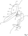
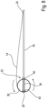
- FIG 1 the use of a wing rig 1 according to the invention for driving a foil board 2 is shown.
- a surfer 4 holds the wing rig 1 with his hands only and adjusts it with respect to the wind depending on the desired direction of travel (upwind, downwind, downwind) or on the lift to be set, for example when jumping or adjusting the ride height.
- the wing rig 1 has an inflatable leading edge 6, which in plan view (from above in the figures 1 and 2 ) is approximately arcuate, preferably approximately delta-, C- or U-shaped and extends with their tips 8, 10 up to a trailing edge 12 of a canopy 14 of the wing rig 1.
- this canopy 14 is supported on the one hand by the leading edge 6 and on the other hand by a tree 16, which is explained in more detail below (see figure 3 ) stretched.
- the surfer 4 holds the wing rig 1 only on the boom 16, which is downwards (as viewed from figure 1 ) protrudes.
- the tree 16 is preferably provided with a covering that simplifies/optimizes gripping and holding.
- the Leading Edge 6 is visible both in plan ( figure 2 ) as well as in a front view - seen in the direction of flow - (see figure 4 ) V-shaped or U-shaped, with the V/U widening upwards, ie away from the surfer when viewed from the front. How figure 1 can be removed, the trailing edge 12 and thus the entire canopy surface 14 is set in a V (or U) shape when viewed from the front.
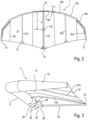
- figure 2 shows a plan view of the wing rig 1 according to FIG figure 1 .
- the approximately arched or delta-shaped, approximately U-shaped or C-shaped leading edge 6 can be seen, which extends to the trailing edge 12 of the canopy 14 .
- the leading edge 6 is formed in the manner of a kite by a front tube, in which a bladder is accommodated, which is inflated via a valve, the pressure being selected such that the structure of the wing rig 1 is maintained even at high wind speeds and driving speeds is guaranteed.
- the leading edge 6 is formed by a large number of tube segments 18a, 18b, 18c, 18d, 18e (for the sake of simplicity, only half of the trailing edge 12 is provided with reference symbols), whose angle of incidence ⁇ to the horizontal is in figure 2 (ie, for example towards a connecting line between the two tips 8, 10) from an apex 20 to the tips 8, 10 increases.
- This angle of attack ⁇ is drawn in as an example for the tube segment 18a.
- the center of area (center of canopy) is identified by reference number 22 .
- This centroid 22 is offset from the apex 20 by at least 40 percent of the distance between the apex 20 and the corresponding apex 24 of the trailing edge 12 .
- the distance between the parting 20, 24 is in figure 2 marked with the reference a.
- the distance b between the vertex 20 and the centroid 22 is at least 40 percent of the distance a.
- This center of area 22 is selected in such a way that the surfer 4 can grip the tree 16, which will be explained in more detail below, in an optimal manner and can thus support the acting wind forces in order, for example, to travel an optimal upwind course.
- a central center batten 23 and two battens 27a, 27b offset towards the tips 8, 10 are provided, which extend between the leading edge 4 and the trailing edge 12 and are inserted into corresponding batten pockets of the canopy 14.
- This insertion takes place in a manner known per se with a certain pretension which is selected according to the desired profiling or can also be changed in order to be able to adapt the profile to different wind speeds.
- the Tube forming the leading edge 10 spans the canopy 14 together with the boom 16 and the sail battens 23, 27, with the boom 16 also engages the apex 24 of the trailing edge 12 of the canopy 14 and is preferably not connected to the canopy 14 therebetween.
- the center batten 23 extends parallel to the longitudinal extent of the boom 16 between the leading edge 6 and the trailing edge 12. Accordingly, this batten 23 also engages on the one hand in the apex 20 of the leading edge 6 and on the other hand in the apex 24 of the trailing edge 12.
- the boom 16 and the center batten 23 are therefore in the same vertical plane as in figure 2 perpendicular to the drawing plane and in figure 3 lies in the drawing plane.
- the space between the boom and the batten 23 / canopy 14 is therefore free, so that the surfer can freely choose his grip position depending on the manoeuvre/course.
- the Leading Edge 6 is also perpendicular to the plane of the drawing figure 2 profiled. Specifically, the leading edge 6 is V-shaped away from the apex 20 towards the tips 8, 10, with the V (also called opening angle ⁇ )--as in FIG figure 1 shown - upwards, ie away from the tree 16 opens. This V-profile is also formed accordingly in the area of the canopy 14 . This is achieved, inter alia, in that the tree 16 has the apex 24 in the representation according to FIG figure 3 down, ie stretches away from the tips 8, 10 and thus forms the V-shape, which is determined by the opening angle ⁇ .
- the structure of the wing rig 1 is designed in such a way that this opening angle ⁇ decreases in the flow state, since the tips 8, 10 deflect upwards (away from the surfer 4) due to the load.
- the tree 16 acts on the area of the apex 20 of the leading edge 6 that is at a distance from the canopy 14 (located below).
- the V shape is particularly evident in the front view figure 4 visible.
- the leading edge 6 formed by the tube is arranged pointing towards the viewer.
- the canopy 14 is set in a corresponding V-shape.
- the angle of inclination ⁇ of the leading edge 6 is maximum in the area of the apex 20 .
- this angle of inclination is ⁇ , ie the angle between the horizontal (parallel to the connecting line of the tips 8, 10) and the tube segment 18a is approximately 20°, for example.
- the next tube segment 18b is then slightly flatter, so that the angle is 15°, for example.
- the angle of inclination of the following segments 18c, 18d, 18e is then flatter again, with the angle of inclination ⁇ in the region of segment 18c being able to be 5°, for example.
- the “mean” angle of inclination ⁇ seen over the entire wing rig 1 is 10°, for example, so that the “mean” opening angle is then about 160°.
- the tree 16 is designed without braces - this is a major difference from the complex structures described above, in which the tree with a variety of transverse and Oblique struts is performed.
- the tree 16 can be detachably fastened to the apex 20 of the leading edge 6 via a holder 25 .
- the holder 25 has a support bracket 26, which is formed according to the outer contour of the apex 20 and this partially surrounds. This gripping takes place in such a way that, with comparatively high wind pressure, the tube rotates, d. That is, the tube segments 18a forming the apex 20 in the direction of the arrow, and thus twisting of the profile, are reliably prevented.
- the support bracket 26 is then followed in the direction of the tree 16 by a receptacle 28 into which the tree 16 is inserted.
- the end sections of the support bracket 26 and the receptacle 28 are connected via a curved handle 30, which makes it easier for the surfer 4 to handle the wing rig 1 before and after use.
- the wing rig 1 can be held by the handle 30 in order to allow it to blow out in the wind.
- the bracket 25 and the tree 16 are preferably made of a light material, for example aluminum, fiber-reinforced plastic, carbon fiber materials or other high-strength lightweight materials. Due to the simple structure of the boom 16, this affects the overall weight of the wing rig 1 insignificantly.
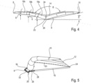
- figure 5 shows a side view of a variant of the above-described embodiment of a wing rig 1.
- the view corresponds approximately to that of FIG figure 3 . That is, visible in this view is the tip 10 with the V-shaped leading edge 6, which has its lowest point in the area of the apex 20.
- the apex 24 of the trailing edge 12 is descended from the tree 16 (as viewed in figure 5 down) tense.
- the holder 25 of the tree 16 in turn has a receptacle 28 into which the tree 16 is inserted or which is connected to the tree 16 in some other way.
- the apex 20 is based according to figure 6 at the top of the recording 28 from.
- a lightweight, approximately U-shaped handle 32 extends away from the receptacle 28, the end section of which is offset at a distance from the point where the apex 20 rests on the receptacle 28, i.e. towards the canopy 14 at the apex 20 formed by the tube segments 18a attacks.
- the handle 32 Due to the U-structure of the handle 32, the wing rig 1 can be held in a simple manner for blowing out.
- the handle 32 is designed as a framework structure.
- the attachment of the receptacle 28 and the end section 34 to the apex can be formed using suitable fixing elements on the tube segments 18a. These fixing elements are preferably designed in such a way that the handle 30 is detachably connected to the leading edge 6 (front tube).
- handle 32 can also be designed as a loop on the inflow side of the leading edge 6, so that the surfer can let the wing rig 1 wave out while holding it in his hand, for example.
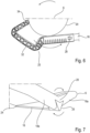
- figure 7 shows an exemplary embodiment in which the holder 25 is designed as a flat body which is designed to encompass the trailing edge 6 or the tube segments 18a in sections.
- This flat mount can be designed as a molded body, for example.
- the holder 25 is made of canvas, which is connected to the apex 20 of the leading edge 6 and is possibly stabilized by suitable stiffening elements. The tree 16 can then in turn be inserted into this holder 25 .
- the holder 25 is designed in such a way that the tube (leading edge 6 ) is prevented from rotating in the direction of the arrow by being supported by the tree 16 .
- the front tube is designed with a continuous bladder.
- a separate bladder is preferably used for each half of the wing rig, whereby between these two bladders according to the illustration in figure 8 a Support channel 36 remains, in which the tree 16 is inserted.
- This support channel 36 can be formed, for example, by a piece of pipe that diametrically penetrates the front tube.
- This support channel 36 is formed between the two bladders of the two wing rig halves (left, right).
- a bearing ring 40 is formed on an outer shell 38 of the front tube (leading edge 6), which runs as an extension of the support channel 36 and through which the boom 16 passes.
- This bearing ring 40 absorbs the compression forces and is designed in a similar way to the support rings of the kite valves that are commonly used.
- a similar support ring 42 is provided opposite the bearing ring 40 on the inside of the outer shell 38 on which the in figure 8 left end portion of the tree 16 is supported. That is, the boom 16 is connected to the outer shell 38 in a non-positive and positive manner, so that the apex 20 and thus the front tube are prevented from twisting in the direction of the arrow. As explained, the tubular support channel 36 is connected to the bearing ring 40 on the one hand and the support ring 42 on the other hand, so that the tree 16 is reliably fixed in position.
- Such a solution has the advantage that the bearing rings 40 and the support rings 42 can be used for practically any front tube diameter—only the length of the support channel 36 has to be adjusted.
- the boom 16 is supported very stably, so that the holding forces introduced by the surfer 4 and also the compression forces transmitted by the front tube are reliably absorbed without the boom 16 being excessively deformed.
- the support channel 36 and the rings 40, 42 are preferably designed as plastic injection molded parts.
- the canopy 14 can be stabilized using battens or the like. These sail battens can be conical or profiled in order to optimize the inflow profile of the canopy 14.
- the leading edge 16 can also have suitable Stiffening elements are stiffened so that the wing rig 1 keeps the aerodynamically optimized shape shown even under high loads.
- These sail battens or stiffening elements can also be designed as carbon fiber tubes or the like.
- the sail battens are profiled in such a way that they are initially adapted to the diameter of the leading edge 6 (front tube) and then support the canopy 14 .
- additional or alternative sail battens can be inserted from the trailing edge 12 into the canopy 14.
- wing rig 1 In order to prevent the wing rig 1 from drifting off in the event of a fall, it is connected to the surfer 4, in particular to his arm, via a safety leash 44.
- a hand-supported wing rig is disclosed, which is preferably designed with an inflatable leading edge, this being designed to widen upwards (away from the surfer) in an approximately V-shaped or U-shaped manner in the direction of flow.
Abstract
Offenbart ist ein handgestütztes Flügelrigg, das vorzugsweise mit einer aufblasbaren Leading Edge ausgeführt ist, wobei diese sich in Anströmrichtung etwa V- oder U-förmig nach oben (weg vom Surfer) erweiternd ausgeführt ist.A hand-supported wing rig is disclosed, which is preferably designed with an inflatable leading edge, this being designed to widen upwards (away from the surfer) in an approximately V-shaped or U-shaped manner in the direction of flow.
Description
Die Erfindung betrifft ein handgestütztes Flügelrigg für windkraftgetriebene Sportarten, beispielsweise Foilsurfen, gemäß dem Oberbegriff des Patentanspruchs 1.The invention relates to a hand-supported wing rig for wind-powered sports, such as foil surfing, according to the preamble of patent claim 1.
Ein derartiges Flügelrigg wird unter dem Namen "Slingwing" im Internet beschrieben. Es handelt sich dabei im Prinzip um einen Kite mit einer Leading Edge und einer einzigen Strut, die aufblasbar (inflatable) ausgeführt sind. An der mittigen Strut und an der Leading Edge sind jeweils Halteschlaufen ausgebildet, über die der Nutzer das inflatable Flügelrigg während der Nutzung, beispielsweise beim Foilen oder beim Eisskaten oder beim Skifahren hält.Such a wing rig is described under the name "Slingwing" on the Internet. It is basically a kite with a leading edge and a single strut that are inflatable. On the central strut and on the leading edge there are holding loops, which the user uses to hold the inflatable wing rig during use, for example when foiling or ice skating or skiing.
Dieses an die Aerodynamik von Kites angepasste inflatable Flügelrigg wird während der Nutzung, insbesondere bei den beim Foilen erreichten hohen Geschwindigkeiten stark deformiert, und somit die Aerodynamik verschlechtert.This inflatable wing rig, which is adapted to the aerodynamics of kites, is severely deformed during use, especially at the high speeds achieved when foiling, and the aerodynamics are thus impaired.
In der
Ein Nachteil dieser Lösung ist, dass durch den komplexen Aufbau des Baums und der Leading Edge das Gesamtgewicht des Flügelriggs sehr hoch ist, so dass eine Nutzung beim Wassersport nur mit entsprechenden Auftriebskörpern möglich ist. Ein weiterer Nachteil besteht darin, dass der Auf- und Abbau des Flügelriggs aufgrund der komplexen Rohrstruktur viel Zeit in Anspruch nimmt. Diese harte Rohrstruktur der Leading Edge und des Baums bringt auch eine erhebliche Verletzungsgefahr des Nutzers bei einem Schleudersturz mit sich.A disadvantage of this solution is that due to the complex structure of the boom and the leading edge, the total weight of the wing rig is very high, so that it can only be used in water sports with the appropriate buoyancy devices. Another disadvantage is that the erection and dismantling of the wing rig due to the complex pipe structure takes a lot of time. This hard tubular structure of the leading edge and the tree also poses a significant risk of injury to the user in a skid fall.
Ein ähnliches starres Flügelrigg ist in der
In der Druckschrift
In dem Dokument
Demgegenüber liegt der Erfindung die Aufgabe zugrunde, ein handgestütztes Flügelrigg zu schaffen, das einen einfachen Aufbau ermöglicht und auch bei hohen Fahrgeschwindigkeiten ein aerodynamisch optimiertes Profil beibehält.In contrast, the invention is based on the object of creating a hand-supported wing rig that enables a simple structure and maintains an aerodynamically optimized profile even at high driving speeds.
Diese Aufgabe wird durch ein handgestütztes Flügelrigg mit den Merkmalen des Patentanspruchs 1 gelöst.This object is achieved by a hand-supported wing rig having the features of patent claim 1.
Vorteilhafte Weiterbildungen der Erfindung sind Gegenstand der Unteransprüche.Advantageous developments of the invention are the subject matter of the dependent claims.
Das erfindungsgemäße handgestützte Flügelrigg ist für windkraftgetriebene Sportarten, beispielsweise für das Foilsurfen und die damit einhergehenden hohen Geschwindigkeiten geeignet. Das Flügelrigg hat eine, vorzugsweise inflatable ausgeführte, Leading Edge, von der sich ein Baum erstreckt, wobei die Leading Edge und der Baum eine Canopy aufspannen. Das Flügelrigg wird während der Nutzung insbesondere am Baum gehalten. Die Leading Edge ist von einer Anbindung des Baums weg zum Achterliek (Trailing Edge) der Canopy hin in einer Draufsicht etwa bogenförmig, deltaförmig, U- oder C-förmig gekrümmt ausgeführt. Die Leading Edge ist des Weiteren im nicht angeströmten oder unbelasteten Zustand in einer in Anströmrichtung gesehenen Frontansicht etwa V- oder U-förmig ausgebildet, wobei dieses Profil zum Baum hin konvergiert. Mit anderen Worten gesagt, das Profil öffnet sich bei der Nutzung nach oben, weg vom Fahrer. Es zeigte sich überraschender Weise, dass sich durch eine derartige ausgeprägte V- oder U-Profilierung und die bogenförmige, deltaförmige oder U- bzw. C-förmige Ausgestaltung der Leading Edge (in einer Draufsicht gesehen) auch bei hohen Wind- und Fahrgeschwindigkeiten ein aerodynamisch optimiertes Profil einstellt, das sich zum einen bei Böen selbsttätig öffnet und somit den resultierenden, vom Nutzer abzustützenden Druck verringert und zum anderen auch bei den hohen Fahrgeschwindigkeiten einen geringen aerodynamischen Widerstand erzeugt. Durch entsprechende Anstellung des Flügelriggs kann dabei in Abhängigkeit von der Windeinfallrichtung eine maximale Fahrgeschwindigkeit oder aber auch ein maximaler Auftrieb für Sprünge oder dergleichen generiert werden.The hand-supported wing rig according to the invention is suitable for wind-driven sports, for example foil surfing, and the high speeds associated therewith. The wing rig has a leading edge, preferably designed to be inflatable, from which a tree extends, the leading edge and the tree open a canopy. The wing rig is held in particular on the tree during use. The leading edge is designed curved from a connection of the tree away to the leech (trailing edge) of the canopy in a top view approximately arc-shaped, delta-shaped, U-shaped or C-shaped. Furthermore, the leading edge is approximately V-shaped or U-shaped in a front view seen in the direction of flow when there is no flow or no load, with this profile converging towards the tree. In other words, the profile opens upwards, away from the driver, during use. Surprisingly, it turned out that such a pronounced V or U profile and the arched, delta-shaped or U- or C-shaped design of the leading edge (seen in a top view) result in an aerodynamic optimized profile, which on the one hand opens automatically in gusts and thus reduces the resulting pressure to be supported by the user and on the other hand generates low aerodynamic resistance even at high driving speeds. By adjusting the wing rig accordingly, a maximum driving speed or also a maximum lift for jumps or the like can be generated depending on the direction of the wind.
Erfindungsgemäß ist der Baum vorzugsweise als starres, nicht inflatable Bauteil ausgebildet. Unter dem Begriff "starres Bauteil" wird dabei eine aus einem weitgehend formsteifen Material ausgebildete Struktur verstanden, diese kann jedoch ohne weiteres zerlegbar oder aber auch teleskopierbar ausgeführt sein. Der Baum ist so ausgebildet, dass ein Halten des Flügelriggs während der Nutzung vereinfacht ist.According to the invention, the tree is preferably designed as a rigid, non-inflatable component. The term "rigid component" is understood to mean a structure formed from a largely dimensionally stable material, but this can be easily dismantled or else made telescopic. The boom is designed to make holding the wing rig easier during use.
Der Baum ist vorzugsweise mit einer den Griffschluss/Reibschluss verbessernden Ummantelung ausgeführt.The tree is preferably designed with a covering that improves grip/friction.
Bei einem besonders bevorzugten Ausführungsbeispiel verläuft das etwa V- oder U-förmige Profil von der Leading Edge weg hin zur Trailing Edge der Canopy. D. h., das gesamte Flügelriggprofil ist in der Frontansicht (in Anströmrichtung gesehen) sich nach oben öffnend profiliert.In a particularly preferred embodiment, the approximately V- or U-shaped profile runs away from the leading edge towards the trailing edge of the canopy. That is, the entire wing rig profile is profiled in the front view (seen in the direction of flow) opening upwards.
Der Wirkungsgrad des Flügelriggs wird weiter verbessert, wenn der V- oder U-Winkel im Anbindungsbereich des Baums maximal ist und zu den Tips hin abnimmt. Dabei wird es bevorzugt, wenn der Neigungswinkel zur Horizontalen (Parallele zur Verbindungslinie durch die Tips) im Scheitelbereich zwischen 10° und 30°, vorzugsweise mehr als 15°, besonders bevorzugt etwa 20° beträgt. Dabei wird unter dem "Neigungswinkel" derjenige Winkel verstanden, den der jeweilige Bereich der Leading Edge bei einer Positionierung des Flügelriggs parallel zur Wasseroberfläche/Nutzoberfläche, d. h. zur Horizontalen einnimmt. Der Öffnungswinkel zwischen den zueinander angestellten/geneigten Leading-Edge-Bereichen entspricht dann der Differenz zwischen 180° und dem Zweifachen des Neigungswinkels (Ergänzungswinkel zu 180°). Die Trailing Edge (Achterliek) ist mit einem entsprechenden Profilwinkel ausgeführt.The efficiency of the wing rig is further improved when the V or U angle is maximum in the boom attachment area and decreases towards the tips. It is preferred if the angle of inclination to the horizontal (parallel to the connecting line through the tips) in the apex area is between 10° and 30°, preferably more than 15°, particularly preferably about 20°. The "angle of inclination" is understood to mean the angle that the respective area of the leading edge makes when the wing rig is positioned parallel to the water surface/usable surface, i. H. to the horizontal. The opening angle between the leading edge areas that are inclined towards one another then corresponds to the difference between 180° and twice the angle of inclination (additional angle to 180°). The trailing edge (leech) is designed with a corresponding profile angle.
Die Aerodynamik ist weiter verbessert, wenn der Neigungswinkel im Tipbereich zwischen 0° bis 20°, vorzugsweise mehr als 1°, vorzugsweise etwa 5° beträgt.The aerodynamics are further improved if the angle of inclination in the tip area is between 0° and 20°, preferably more than 1°, preferably about 5°.
Das Flügelrigg ist bei einer Variante der Erfindung so ausgeführt, dass der mittlere Neigungswinkel, d. h., der Winkel vom Scheitel der Leading Edge bis zum jeweiligen Tip 5° bis 20°, vorzugsweise etwa 10° beträgt.In a variant of the invention, the wing rig is designed in such a way that the mean angle of inclination, i. That is, the angle from the apex of the leading edge to the respective tip is 5° to 20°, preferably about 10°.
Zur Anpassung an mehrere Flügelrigg-Größen kann der Baum teleskopierbar oder aus mehreren auswechselbaren Teilstücken bestehend ausgebildet werden.To adapt to several wing rig sizes, the boom can be made telescopic or made up of several interchangeable sections.
Der vorrichtungstechnische Aufwand ist besonders gering, wenn der Baum mittels einer Halterung auswechselbar an der Leading Edge und der Trailing Edge befestigt ist. Auf diese Weise kann ein einziger Baum für mehrere Flügelriggs verwendet werden.The outlay in terms of device technology is particularly low if the tree is fastened to the leading edge and the trailing edge in an exchangeable manner by means of a holder. This way a single boom can be used for multiple wing rigs.
Zur Minimierung des Gewichtes ist es vorteilhaft, den Baum rohrförmig auszubilden.In order to minimize the weight, it is advantageous to design the boom in a tubular shape.
Die Flugstabilität des Flügelriggs wird weiter verbessert, wenn die Halterung des Baums derart ausgebildet ist, dass sie eine Rotation der Leading Edge um ihre Längsachse behindert.The flight stability of the wing rig is further improved if the boom holder is designed in such a way that it prevents the leading edge from rotating about its longitudinal axis.
Dabei wird es besonders bevorzugt, wenn die Halterung die Leading Edge abschnittsweise umgreift und somit eine Rotation unterbindet.In this case, it is particularly preferred if the holder encompasses the leading edge in sections and thus prevents rotation.
Bei einer alternativen Lösung kann die Halterung auch die Leading Edge durchsetzen. Bei einer derartigen Ausgestaltung müssen dann an der Leading Edge entsprechende Aufnahmen für die Halterung bzw. den Baum ausgebildet sein. Des Weiteren sollte ein Kanal vorgesehen werden, in den die Halterung oder der Baum eingesetzt werden kann.In an alternative solution, the bracket can also enforce the leading edge. With such an embodiment, corresponding receptacles for the holder or the tree must then be formed on the leading edge. A channel should also be provided into which the bracket or tree can be inserted.
Bei einer besonders bevorzugten Variante des Flügelriggs ist der Baum unverstrebt ausgeführt. Eine derartige Lösung ist zum einen gewichtsoptimiert und ermöglicht es zum anderen, dass der Nutzer den Baum und somit das Flügelrigg in Abhängigkeit vom jeweiligen Fahrmanöver und den Umgebungsbedingungen variabel halten kann.In a particularly preferred variant of the wing rig, the boom is designed without bracing. On the one hand, such a solution is weight-optimized and, on the other hand, it enables the user to hold the boom and thus the wing rig variably depending on the respective driving maneuver and the environmental conditions.
Bei einer besonders bevorzugten Ausführungsform des Flügelriggs ist der Flächenschwerpunkt (center of Canopy) zumindest 30 Prozent, vorzugsweise mehr als 40 Prozent des Abstandes zwischen dem Scheitel der Leading Edge und der Trailing Edge (Achterliek) von der Leading Edge entfernt.In a particularly preferred embodiment of the wing rig, the center of canopy is at least 30 percent, preferably more than 40 percent of the distance between the apex of the leading edge and the trailing edge (leech) away from the leading edge.
Zur weiteren Optimierung des Anströmprofils kann die Leading Edge und/oder die Canopy mittels Versteifungselementen, beispielsweise Segellatten versteift sein.To further optimize the inflow profile, the leading edge and/or the canopy can be stiffened by means of stiffening elements, for example battens.
Diese Segellatten können ihrerseits zur Profilierung des Flügelprofils gekrümmt und/oder verjüngt sein.These sail battens can in turn be curved and/or tapered to give the wing profile a profile.
Bei einem besonders bevorzugten Ausführungsbeispiel erstreckt sich eine Segellatte von der Leading Edge zur Trailing Edge, wobei diese Segellatte derart positioniert ist, dass sie mit dem Baum in einer Vertikalebene (bei horizontaler Ausrichtung des Flügelriggs) liegt.In a particularly preferred embodiment, a batten extends from the leading edge to the trailing edge, the batten being positioned so that it is in a vertical plane with the boom (when the wing rig is horizontal).
Zur Vereinfachung der Handhabung kann im Anbindungsbereich des Baums vorzugsweise an der Leading Edge ein Handgriff vorgesehen werden.To simplify handling, a handle can be provided in the connection area of the tree, preferably on the leading edge.
Um bei einem Sturz das Trennen vom Nutzer zu verhindern, ist das Flügelrigg mit einer Safetyleash ausgeführt.In order to prevent separation from the user in the event of a fall, the wing rig is equipped with a safety leash.
Die Anmelderin behält sich vor, auf ein Flügelrigg mit dem vorbeschriebenen V- oder U-förmigen Profil und einer starren, nicht inflatable Leading Edge einen eigenen nebengeordneten Anspruch zu richten.The applicant reserves the right to direct a secondary claim to a wing rig with the above-described V- or U-shaped profile and a rigid, non-inflatable leading edge.
Die Halterung zur Anbindung des Baums an die Leading Edge kann beispielsweise durch ein Profilstück ausgebildet sein, das die Leading Edge abschnittsweise umgreift und über geeignete Befestigungsmittel an die Leading Edge angesetzt ist. Der Baum wird dann in das Profilstück eingesteckt oder in sonstiger Weise mit diesem verbunden.The holder for connecting the tree to the leading edge can be formed, for example, by a profile piece that partially surrounds the leading edge and is attached to the leading edge using suitable fastening means. The tree is then inserted into the profile piece or connected to it in some other way.
Bei einer alternativen Lösung ist an der Leading Edge mittels Profilteilen oder Segeltuch eine Halterung für den Baum ausgebildet. Diese Profilteile umgreifen die Leading Edge wiederum abschnittsweise, so dass eine Rotation der Leading Edge während der Nutzung unterbunden ist.In an alternative solution, a bracket for the tree is formed on the leading edge using profile parts or canvas. These profile parts in turn surround the leading edge in sections, so that the leading edge is prevented from rotating during use.
Der Baum erstreckt sich vorzugsweise von der Leading Edge bis zur Trailing Edge, ohne in den dazwischenliegenden Bereichen direkt oder fest mit der Canopy verbunden zu sein, sodass praktisch die gesamte Baumlänge als Griffbereich zur Verfügung steht. Dadurch ist gewährleistet, dass das Halten des Flügelriggs bei jedweden Manövern in optimaler Weise nach den Vorlieben des Nutzers gewählt werden kann. Des Weiteren kann durch Verstellen der Baumlänge die Profiltiefe eingestellt werden.The tree preferably extends from the leading edge to the trailing edge without being directly or firmly connected to the canopy in the areas in between, so that practically the entire length of the tree is available as a grip area. This ensures that the holding of the wing rig during any maneuver can be chosen in an optimal way according to the user's preferences. Furthermore, the profile depth can be adjusted by adjusting the boom length.
Die Struktur des Flügelriggs ist so ausgelegt, dass im angeströmten Zustand, das heißt bei der Nutzung des Flügelriggs, insbesondere der Öffnungswinkel im Bereich der Trailing Edge verringert wird. Das heißt, der Neigungswinkel α der Trailing-Edge-Bereiche zur Horizontalen vergrößert sich bei der Nutzung. Dementsprechend kann sich auch die Profiltiefe im angeströmten Zustand vergrößern. Die Änderung des Öffnungswinkels kann dabei im Trailing-Edge-Bereich größer als im Leading-Edge-Bereich sein.The structure of the wing rig is designed in such a way that the opening angle in the area of the trailing edge is reduced in the flow condition, i.e. when using the wing rig. This means that the angle of inclination α of the trailing edge areas to the horizontal increases with use. Accordingly can also increase the profile depth in the flowed state. The change in the opening angle can be greater in the trailing-edge area than in the leading-edge area.
Der Baum ist vorzugsweise an dem von der Canopy abgewandten Bereich am Scheitel der Leading Edge befestigt.The boom is preferably attached to the apex of the leading edge in the area facing away from the canopy.
Die Befestigung ist derart, dass ein seitliches Verschwenken/Anstellen des Flügelriggs durch Drehen des Baums um seine Längsachse möglich ist - dies wäre mit Schlaufen (Handles) nicht möglich, da diese nicht biegesteif sind und somit kein Drehmoment aufgebracht werden kann.The attachment is such that the wing rig can be swiveled/adjusted to the side by turning the boom around its longitudinal axis - this would not be possible with loops (handles), as these are not rigid and therefore no torque can be applied.
Bevorzugte Ausführungsbeispiele der Erfindung werden im Folgenden anhand schematischer Zeichnungen näher erläutert. Es zeigen:
-
Figur 1 eine Prinzipdarstellung eines ersten Ausführungsbeispiels eines Flügelriggs, das zum Antreiben eines Foilboards verwendet wird; -
Figur 2 eine Draufsicht auf ein Flügelrigg gemäßFigur 1 ; -
Figur 3 eine Seitenansicht des Flügelriggs gemäß denFiguren 1 und2 ; -
Figur 4Figuren 1 bis 3 ; -
Figur 5 eine Seitenansicht eines weiteren Ausführungsbeispiels eines Flügelriggs; -
Figur 6Figur 5 ; -
Figur 7 eine Teildarstellung eines dritten Ausführungsbeispiels eines Flügelriggs und -
Figur 8
-
figure 1 a schematic diagram of a first embodiment of a wing rig that is used to drive a foil board; -
figure 2 a top view of a wing rig according to FIGfigure 1 ; -
figure 3 a side view of the wing rig according to thefigures 1 and2 ; -
figure 4 a front view of a wing rig according to theFigures 1 to 3 ; -
figure 5 a side view of another embodiment of a wing rig; -
figure 6 a detail view of the wing rig according tofigure 5 ; -
figure 7 a partial representation of a third embodiment of a wing rig and -
figure 8 a schematic representation of a fourth embodiment of a wing rig according to the invention.
In
Das Flügelrigg 1 hat eine aufblasbare Leading Edge 6, die in der Draufsicht (von oben her in den
Bei dem dargestellten Ausführungsbeispiel ist die Leading Edge 6 durch eine Vielzahl von Tubesegmenten 18a, 18b, 18c, 18d, 18e (der Einfachheit halber wird nur eine Hälfte der Trailing Edge 12 mit Bezugszeichen versehen) ausgebildet, deren Anstellwinkel α zur Horizontalen in
Dieser Flächenschwerpunkt 22 ist so gewählt, dass der Surfer 4 den im Folgenden noch näher erläuterten Baum 16 in optimaler Weise ergreifen und so die einwirkenden Windkräfte abstützen kann, um beispielsweise einen optimalen Amwind-Kurs zu fahren.This center of
Zur Aussteifung des Flügelprofils sind eine mittlere Center-Segellatte 23 und zwei zu den Tips 8, 10 hin versetzte Segellatten 27a, 27b vorgesehen, die sich zwischen der Leading Edge 4 und der Trailing Edge 12 erstrecken und in entsprechende Segellattentaschen der Canopy 14 eingesetzt sind. Dieses Einsetzen erfolgt in an sich bekannter Weise mit einer gewissen Vorspannung, die entsprechend der gewünschten Profilierung gewählt ist oder auch veränderbar ist, um das Profil an unterschiedliche Windstärken anpassen zu können. Mit dem Bezugszeichen 29 sind in
In der Seitenansicht gemäß
Wie des Weiteren
Die V-Form ist besonders deutlich in der Vorderansicht gemäß
Bei allen beschriebenen Ausführungsbeispielen ist der Baum 16 unverstrebt ausgebildet - dies ist ein wesentlicher Unterschied zu den eingangs beschriebenen komplexen Konstruktionen, bei denen der Baum mit einer Vielzahl von Quer- und Schrägstreben ausgeführt ist. Bei der erfindungsgemäßen Lösung kann der Baum 16 über eine Halterung 25 lösbar am Scheitel 20 der Leading Edge 6 befestigt werden.In all of the described embodiments, the
Beim dargestellten Ausführungsbeispiel hat die Halterung 25 eine Stützkonsole 26, die entsprechend der Außenkontur des Scheitels 20 ausgebildet ist und diesen abschnittsweise umgreift. Dieses Umgreifen erfolgt derart, dass bei vergleichsweise hohem Winddruck eine Rotation der Tube, d. h., der den Scheitel 20 ausbildenden Tubesegmente 18a in Pfeilrichtung und damit ein Verwinden des Profils zuverlässig verhindert wird.In the illustrated embodiment, the
An die Stützkonsole 26 schließt sich dann in Richtung des Baums 16 eine Aufnahme 28 an, in die der Baum 16 eingesteckt wird. Die Endabschnitte der Stützkonsole 26 und der Aufnahme 28 sind über einen bogenförmigen Handgriff 30 verbunden, der dem Surfer 4 das Handling des Flügelriggs 1 vor und nach der Nutzung erleichtert. So kann beispielsweise das Flügelrigg 1 bei Nichtnutzung am Handgriff 30 gehalten werden, um dieses im Wind auswehen zu lassen. Die Halterung 25 und der Baum 16 sind vorzugsweise aus einem leichten Material, beispielsweise aus Aluminium, faserverstärktem Kunststoff, Kohlefasermaterialien oder sonstigen hochfesten Leichtbaumaterialien ausgebildet. Aufgrund der einfachen Struktur des Baums 16 beeinflusst dieser das Gesamtgewicht des Flügelriggs 1 unwesentlich.The
Durch die U-Struktur des Haltegriffs 32 kann das Flügelrigg 1 auf einfache Weise zum Auswehen gehalten werden. Wie insbesondere in
Anstelle des mehr oder weniger in die Baumstruktur integrierter Handgriffs 30, Haltegriffs 32 kann dieser auch als Schlaufe an der Anströmseite der Leading Edge 6 ausgebildet werden, sodass der Surfer das Flügelrigg 1 beispielsweise beim Surfen in der Hand haltend auswehen lassen kann.Instead of the
Diese flächige Halterung kann beispielsweise als Formkörper ausgebildet sein. Bei einem besonders einfach ausgeführten Ausführungsbeispiel ist die Halterung 25 aus Segeltuch ausgebildet, das mit dem Scheitel 20 der Leading Edge 6 verbunden ist und ggf. durch geeignete Versteifungselemente stabilisiert wird. In diese Halterung 25 kann dann wiederum der Baum 16 eingesetzt werden. Auch bei diesem Ausführungsbeispiel ist die Halterung 25 so ausgelegt, dass eine Rotation der Tube (Leading Edge 6) in Pfeilrichtung durch die Abstützung mittels des Baums 16 verhindert wird.This flat mount can be designed as a molded body, for example. In a particularly simple embodiment, the
Bei den vorbeschriebenen Ausführungsbeispielen ist die Fronttube - wie erläutert - mit einer durchgehenden Bladder ausgeführt. Bei dem Ausführungsbeispiel gemäß
Ein ähnlicher Stützring 42 ist gegenüberliegend zum Lagerring 40 an der Innenseite der Außenhülle 38 vorgesehen, an dem der in
Eine derartige Lösung hat den Vorteil, dass die Lagerringe 40 und die Stützringe 42 praktisch für jedweden Fronttubedurchmesser verwendbar sind - es muss lediglich die Länge des Stützkanals 36 angepasst werden. Bei einer derartigen Lösung ist der Baum 16 sehr stabil abgestützt, so dass die vom Surfer 4 eingeleiteten Haltekräfte und auch die von der Fronttube übertragenen Kompressionskräfte zuverlässig aufgenommen werden, ohne dass der Baum 16 übermäßig verformt wird. Der Stützkanal 36 und die Ringe 40, 42 werden vorzugweise als Kunststoffspritzgussteile ausgeführt.Such a solution has the advantage that the bearing rings 40 and the support rings 42 can be used for practically any front tube diameter—only the length of the
Bei allen vorbeschriebenen Ausführungsbeispielen kann die Canopy 14 über Segellatten oder dergleichen stabilisiert werden. Diese Segellatten können konisch ausgebildet oder profiliert sein, um das Anströmprofil der Canopy 14 zu optimieren. In entsprechender Weise kann auch die Leading Edge 16 über geeignete Versteifungselemente ausgesteift werden, so dass das Flügelrigg 1 die dargestellte aerodynamisch optimierte Form auch bei hohen Belastungen hält.In all the exemplary embodiments described above, the
Diese Segellatten oder Versteifungselemente können auch als Kohlefaserrohre oder dergleichen ausgebildet sein.These sail battens or stiffening elements can also be designed as carbon fiber tubes or the like.
Bei einem Ausführungsbeispiel sind die Segellatten derart profiliert, dass sie zunächst an den Durchmesser der Leading Edge 6 (Fronttube) angepasst sind und dann die Canopy 14 abstützen. Selbstverständlich können zusätzlich oder alternativ Segellatten von der Trailing Edge 12 her in die Canopy 14 eingesetzt werden.In one embodiment, the sail battens are profiled in such a way that they are initially adapted to the diameter of the leading edge 6 (front tube) and then support the
Um im Falle eines Sturzes das Abtreiben des Flügelriggs 1 zu verhindern, ist dieses über eine Safety-Leash 44 mit dem Surfer 4, insbesondere mit dessen Arm verbunden.In order to prevent the wing rig 1 from drifting off in the event of a fall, it is connected to the
Offenbart ist ein handgestütztes Flügelrigg, das vorzugsweise mit einer aufblasbaren Leading Edge ausgeführt ist, wobei diese sich in Anströmrichtung etwa V- oder U-förmig nach oben (weg vom Surfer) erweiternd ausgeführt ist.A hand-supported wing rig is disclosed, which is preferably designed with an inflatable leading edge, this being designed to widen upwards (away from the surfer) in an approximately V-shaped or U-shaped manner in the direction of flow.
- 11
- Flügelriggwing rig
- 22
- Foilboardfoil board
- 44
- Surfersurfer
- 66
- Leading Edge / FronttubeLeading edge / front tube
- 88th
- Tiphint
- 1010
- Tiphint
- 1212
- Trailing EdgeTrailing Edge
- 1414
- Canopycanopy
- 1616
- BaumTree
- 1818
- Tubesegmenttube segment
- 2020
- Scheitel der Leading EdgeApex of the Leading Edge
- 2222
- Flächenschwerpunktcentroid
- 2323
- Center-Segellattecenter batten
- 2424
- Scheitel der Trailing Edgeapex of the trailing edge
- 2525
- Halterungbracket
- 2626
- Stützkonsolesupport console
- 2727
- Segellattebatten
- 2828
- AufnahmeRecording
- 2929
- Nahtseam
- 3030
- Handgriffhandle
- 3232
- Haltegriffgrab handle
- 3434
- Endabschnittend section
- 3636
- Stützkanalsupport channel
- 3838
- Außenhülleouter shell
- 4040
- Lagerringbearing ring
- 4242
- Stützringsupport ring
- 4444
- Safety-Leashsafety leash
- αa
- Anstellwinkelangle of attack
- ββ
- Neigungswinkeltilt angle
- γg
- Neigungswinkel zu den TipsAngle of inclination to the tips
- δδ
- Öffnungswinkel (180°-2β)Opening angle (180°-2β)
Claims (11)
Applications Claiming Priority (3)
| Application Number | Priority Date | Filing Date | Title |
|---|---|---|---|
| DE102019101656.8A DE102019101656A1 (en) | 2019-01-23 | 2019-01-23 | Wing rig |
| PCT/EP2020/051463 WO2020152198A1 (en) | 2019-01-23 | 2020-01-22 | Wing rig |
| EP20701589.2A EP3914510B1 (en) | 2019-01-23 | 2020-01-22 | Wing rig |
Related Parent Applications (1)
| Application Number | Title | Priority Date | Filing Date |
|---|---|---|---|
| EP20701589.2A Division EP3914510B1 (en) | 2019-01-23 | 2020-01-22 | Wing rig |
Publications (2)
| Publication Number | Publication Date |
|---|---|
| EP4234389A2 true EP4234389A2 (en) | 2023-08-30 |
| EP4234389A3 EP4234389A3 (en) | 2023-11-08 |
Family
ID=69187793
Family Applications (2)
| Application Number | Title | Priority Date | Filing Date |
|---|---|---|---|
| EP23177722.8A Pending EP4234389A3 (en) | 2019-01-23 | 2020-01-22 | Wing rig |
| EP20701589.2A Active EP3914510B1 (en) | 2019-01-23 | 2020-01-22 | Wing rig |
Family Applications After (1)
| Application Number | Title | Priority Date | Filing Date |
|---|---|---|---|
| EP20701589.2A Active EP3914510B1 (en) | 2019-01-23 | 2020-01-22 | Wing rig |
Country Status (5)
| Country | Link |
|---|---|
| US (1) | US11738840B2 (en) |
| EP (2) | EP4234389A3 (en) |
| DE (2) | DE102019101656A1 (en) |
| ES (1) | ES2952068T3 (en) |
| WO (1) | WO2020152198A1 (en) |
Families Citing this family (12)
| Publication number | Priority date | Publication date | Assignee | Title |
|---|---|---|---|---|
| DE102020122143A1 (en) | 2019-10-31 | 2021-05-06 | Boards & More Gmbh | Wing rig |
| DE102020122145A1 (en) | 2019-10-31 | 2021-05-06 | Boards & More Gmbh | Wing rig |
| DE102019129493A1 (en) | 2019-10-31 | 2021-05-06 | Boards & More Gmbh | Kite and wing rig |
| DE202021101663U1 (en) | 2020-08-17 | 2021-06-22 | Boards & More Gmbh | Wing rig |
| DE102021106993A1 (en) | 2020-08-17 | 2022-02-17 | Boards & More Gmbh | wing rig |
| EP4023546A1 (en) | 2020-12-29 | 2022-07-06 | Boards & More GmbH | Wing rig |
| WO2022218921A1 (en) | 2021-04-12 | 2022-10-20 | F. One | Self-contained traction wing |
| FR3121657A1 (en) | 2021-04-12 | 2022-10-14 | F. One | Autonomous traction wing |
| EP4323272A1 (en) | 2021-04-15 | 2024-02-21 | Boards & More GmbH | Wing foil and kite |
| DE102021125438A1 (en) | 2021-04-15 | 2022-10-20 | Boards & More Gmbh | wing rig |
| DE102021214265A1 (en) | 2021-12-13 | 2023-06-15 | Boards & More Gmbh | wing |
| WO2023195035A1 (en) * | 2022-04-06 | 2023-10-12 | Zm Design S.R.L. | Inflatable wing sail with aero-optimised leading edge |
Citations (4)
| Publication number | Priority date | Publication date | Assignee | Title |
|---|---|---|---|---|
| DE3140685A1 (en) | 1981-10-13 | 1983-04-28 | James R. 90402 Santa Monica Calif. Drake | "HAND SAIL" |
| US4563969A (en) | 1981-03-11 | 1986-01-14 | Le Bail Roland C | Sail having variable propelling and lifting effects |
| WO1995005973A1 (en) | 1993-08-20 | 1995-03-02 | Oy Skywings Ab | Wing sail |
| US5448961A (en) | 1992-07-13 | 1995-09-12 | Ansteensen; Erik | User supported portable sail |
Family Cites Families (8)
| Publication number | Priority date | Publication date | Assignee | Title |
|---|---|---|---|---|
| US3487800A (en) * | 1968-03-27 | 1970-01-06 | Hoyle Schweitzer | Wind-propelled apparatus |
| DE3406040A1 (en) * | 1983-10-18 | 1985-08-22 | Otto Dr.med. 5000 Köln Jung | Dragon rig |
| US4533159A (en) * | 1984-04-27 | 1985-08-06 | Seidel John C | Wind propulsion apparatus |
| DE3421503A1 (en) * | 1984-06-08 | 1985-12-12 | Fritz 8200 Rosenheim Eib | Lightweight wing |
| US4742977A (en) * | 1986-11-03 | 1988-05-10 | Crowell Robert L | Wing structure with self-induced camber |
| GB8706134D0 (en) * | 1987-03-16 | 1987-04-23 | Jacobson B J | Inflatable aerodynamic wing structure |
| DE60006646D1 (en) * | 2000-05-05 | 2003-12-24 | Gesuino Petretto | hang-glider |
| DE102016113858B4 (en) * | 2016-03-07 | 2018-03-29 | Boards & More Gmbh | kite |
-
2019
- 2019-01-23 DE DE102019101656.8A patent/DE102019101656A1/en active Pending
-
2020
- 2020-01-22 ES ES20701589T patent/ES2952068T3/en active Active
- 2020-01-22 US US17/425,168 patent/US11738840B2/en active Active
- 2020-01-22 DE DE212020000445.5U patent/DE212020000445U1/en active Active
- 2020-01-22 EP EP23177722.8A patent/EP4234389A3/en active Pending
- 2020-01-22 WO PCT/EP2020/051463 patent/WO2020152198A1/en unknown
- 2020-01-22 EP EP20701589.2A patent/EP3914510B1/en active Active
Patent Citations (4)
| Publication number | Priority date | Publication date | Assignee | Title |
|---|---|---|---|---|
| US4563969A (en) | 1981-03-11 | 1986-01-14 | Le Bail Roland C | Sail having variable propelling and lifting effects |
| DE3140685A1 (en) | 1981-10-13 | 1983-04-28 | James R. 90402 Santa Monica Calif. Drake | "HAND SAIL" |
| US5448961A (en) | 1992-07-13 | 1995-09-12 | Ansteensen; Erik | User supported portable sail |
| WO1995005973A1 (en) | 1993-08-20 | 1995-03-02 | Oy Skywings Ab | Wing sail |
Also Published As
| Publication number | Publication date |
|---|---|
| US20220119086A1 (en) | 2022-04-21 |
| EP3914510A1 (en) | 2021-12-01 |
| US11738840B2 (en) | 2023-08-29 |
| WO2020152198A1 (en) | 2020-07-30 |
| DE212020000445U1 (en) | 2021-04-06 |
| ES2952068T3 (en) | 2023-10-26 |
| EP3914510B1 (en) | 2023-06-07 |
| EP4234389A3 (en) | 2023-11-08 |
| DE102019101656A1 (en) | 2020-07-23 |
Similar Documents
| Publication | Publication Date | Title |
|---|---|---|
| EP3914510B1 (en) | Wing rig | |
| EP4051577B1 (en) | Wing rig | |
| EP3405386B1 (en) | Mast and corresponding rig, in particular for a surfboard | |
| EP3215418B1 (en) | Sailing rig | |
| EP4051576A1 (en) | Wing rig | |
| DE102021106993A1 (en) | wing rig | |
| EP4023546A1 (en) | Wing rig | |
| EP4097001B1 (en) | Wing rig | |
| EP0076954B1 (en) | Hand-held sail | |
| DE102021112724A1 (en) | wing rig | |
| DE202015102731U1 (en) | Segelrigg | |
| EP0103829A2 (en) | Rig for sailboards | |
| WO1985000333A1 (en) | Sail rig | |
| DE3104750A1 (en) | Rig in wing form for vessels furnished with sails | |
| DE19616068A1 (en) | Winglet for sand yacht | |
| DE102021214265A1 (en) | wing | |
| DE19751858B4 (en) | Rigging for sailing vessels | |
| EP4323272A1 (en) | Wing foil and kite | |
| DE102004029432B4 (en) | Device for handling sails and sail guidance devices on a vehicle powered by wind power | |
| DE102015102062A1 (en) | Segelrigg | |
| DE19510680A1 (en) | Wind drive device for single-hull ships | |
| DE3842869C2 (en) | ||
| DE202007018167U1 (en) | Surf or sail rigging and sails for such a rig | |
| DE102015118216A1 (en) | Segelrigg | |
| DE19950625A1 (en) | Catamaran has one hull acting as a boom for the sail on the windward side with a mainsheet from the upper part of the sailing rig to the boom hull to counteract forces on the mast foot |
Legal Events
| Date | Code | Title | Description |
|---|---|---|---|
| PUAI | Public reference made under article 153(3) epc to a published international application that has entered the european phase |
Free format text: ORIGINAL CODE: 0009012 |
|
| STAA | Information on the status of an ep patent application or granted ep patent |
Free format text: STATUS: THE APPLICATION HAS BEEN PUBLISHED |
|
| AC | Divisional application: reference to earlier application |
Ref document number: 3914510 Country of ref document: EP Kind code of ref document: P |
|
| AK | Designated contracting states |
Kind code of ref document: A2 Designated state(s): AL AT BE BG CH CY CZ DE DK EE ES FI FR GB GR HR HU IE IS IT LI LT LU LV MC MK MT NL NO PL PT RO RS SE SI SK SM TR |
|
| PUAL | Search report despatched |
Free format text: ORIGINAL CODE: 0009013 |
|
| AK | Designated contracting states |
Kind code of ref document: A3 Designated state(s): AL AT BE BG CH CY CZ DE DK EE ES FI FR GB GR HR HU IE IS IT LI LT LU LV MC MK MT NL NO PL PT RO RS SE SI SK SM TR |
|
| RIC1 | Information provided on ipc code assigned before grant |
Ipc: B63H 8/10 20200101AFI20231004BHEP |