EP4467323A1 - Einstellbarer rohranschlag - Google Patents
Einstellbarer rohranschlag Download PDFInfo
- Publication number
- EP4467323A1 EP4467323A1 EP23175728.7A EP23175728A EP4467323A1 EP 4467323 A1 EP4467323 A1 EP 4467323A1 EP 23175728 A EP23175728 A EP 23175728A EP 4467323 A1 EP4467323 A1 EP 4467323A1
- Authority
- EP
- European Patent Office
- Prior art keywords
- stop
- pipe
- holder
- pipe stop
- disks
- Prior art date
- Legal status (The legal status is an assumption and is not a legal conclusion. Google has not performed a legal analysis and makes no representation as to the accuracy of the status listed.)
- Granted
Links
Images

Classifications
-
- B—PERFORMING OPERATIONS; TRANSPORTING
- B29—WORKING OF PLASTICS; WORKING OF SUBSTANCES IN A PLASTIC STATE IN GENERAL
- B29C—SHAPING OR JOINING OF PLASTICS; SHAPING OF MATERIAL IN A PLASTIC STATE, NOT OTHERWISE PROVIDED FOR; AFTER-TREATMENT OF THE SHAPED PRODUCTS, e.g. REPAIRING
- B29C66/00—General aspects of processes or apparatus for joining preformed parts
- B29C66/50—General aspects of joining tubular articles; General aspects of joining long products, i.e. bars or profiled elements; General aspects of joining single elements to tubular articles, hollow articles or bars; General aspects of joining several hollow-preforms to form hollow or tubular articles
- B29C66/51—Joining tubular articles, profiled elements or bars; Joining single elements to tubular articles, hollow articles or bars; Joining several hollow-preforms to form hollow or tubular articles
- B29C66/52—Joining tubular articles, bars or profiled elements
- B29C66/522—Joining tubular articles
- B29C66/5221—Joining tubular articles for forming coaxial connections, i.e. the tubular articles to be joined forming a zero angle relative to each other
-
- B—PERFORMING OPERATIONS; TRANSPORTING
- B23—MACHINE TOOLS; METAL-WORKING NOT OTHERWISE PROVIDED FOR
- B23K—SOLDERING OR UNSOLDERING; WELDING; CLADDING OR PLATING BY SOLDERING OR WELDING; CUTTING BY APPLYING HEAT LOCALLY, e.g. FLAME CUTTING; WORKING BY LASER BEAM
- B23K37/00—Auxiliary devices or processes, not specially adapted for a procedure covered by only one of the other main groups of this subclass
- B23K37/04—Auxiliary devices or processes, not specially adapted for a procedure covered by only one of the other main groups of this subclass for holding or positioning work
- B23K37/053—Auxiliary devices or processes, not specially adapted for a procedure covered by only one of the other main groups of this subclass for holding or positioning work aligning cylindrical work; Clamping devices therefor
-
- B—PERFORMING OPERATIONS; TRANSPORTING
- B29—WORKING OF PLASTICS; WORKING OF SUBSTANCES IN A PLASTIC STATE IN GENERAL
- B29C—SHAPING OR JOINING OF PLASTICS; SHAPING OF MATERIAL IN A PLASTIC STATE, NOT OTHERWISE PROVIDED FOR; AFTER-TREATMENT OF THE SHAPED PRODUCTS, e.g. REPAIRING
- B29C65/00—Joining or sealing of preformed parts, e.g. welding of plastics materials; Apparatus therefor
- B29C65/02—Joining or sealing of preformed parts, e.g. welding of plastics materials; Apparatus therefor by heating, with or without pressure
- B29C65/14—Joining or sealing of preformed parts, e.g. welding of plastics materials; Apparatus therefor by heating, with or without pressure using wave energy, i.e. electromagnetic radiation, or particle radiation
- B29C65/1403—Joining or sealing of preformed parts, e.g. welding of plastics materials; Apparatus therefor by heating, with or without pressure using wave energy, i.e. electromagnetic radiation, or particle radiation characterised by the type of electromagnetic or particle radiation
- B29C65/1412—Infrared [IR] radiation
-
- B—PERFORMING OPERATIONS; TRANSPORTING
- B29—WORKING OF PLASTICS; WORKING OF SUBSTANCES IN A PLASTIC STATE IN GENERAL
- B29C—SHAPING OR JOINING OF PLASTICS; SHAPING OF MATERIAL IN A PLASTIC STATE, NOT OTHERWISE PROVIDED FOR; AFTER-TREATMENT OF THE SHAPED PRODUCTS, e.g. REPAIRING
- B29C65/00—Joining or sealing of preformed parts, e.g. welding of plastics materials; Apparatus therefor
- B29C65/02—Joining or sealing of preformed parts, e.g. welding of plastics materials; Apparatus therefor by heating, with or without pressure
- B29C65/14—Joining or sealing of preformed parts, e.g. welding of plastics materials; Apparatus therefor by heating, with or without pressure using wave energy, i.e. electromagnetic radiation, or particle radiation
- B29C65/1429—Joining or sealing of preformed parts, e.g. welding of plastics materials; Apparatus therefor by heating, with or without pressure using wave energy, i.e. electromagnetic radiation, or particle radiation characterised by the way of heating the interface
- B29C65/1432—Joining or sealing of preformed parts, e.g. welding of plastics materials; Apparatus therefor by heating, with or without pressure using wave energy, i.e. electromagnetic radiation, or particle radiation characterised by the way of heating the interface direct heating of the surfaces to be joined
-
- B—PERFORMING OPERATIONS; TRANSPORTING
- B29—WORKING OF PLASTICS; WORKING OF SUBSTANCES IN A PLASTIC STATE IN GENERAL
- B29C—SHAPING OR JOINING OF PLASTICS; SHAPING OF MATERIAL IN A PLASTIC STATE, NOT OTHERWISE PROVIDED FOR; AFTER-TREATMENT OF THE SHAPED PRODUCTS, e.g. REPAIRING
- B29C65/00—Joining or sealing of preformed parts, e.g. welding of plastics materials; Apparatus therefor
- B29C65/02—Joining or sealing of preformed parts, e.g. welding of plastics materials; Apparatus therefor by heating, with or without pressure
- B29C65/18—Joining or sealing of preformed parts, e.g. welding of plastics materials; Apparatus therefor by heating, with or without pressure using heated tools
- B29C65/20—Joining or sealing of preformed parts, e.g. welding of plastics materials; Apparatus therefor by heating, with or without pressure using heated tools with direct contact, e.g. using "mirror"
-
- B—PERFORMING OPERATIONS; TRANSPORTING
- B29—WORKING OF PLASTICS; WORKING OF SUBSTANCES IN A PLASTIC STATE IN GENERAL
- B29C—SHAPING OR JOINING OF PLASTICS; SHAPING OF MATERIAL IN A PLASTIC STATE, NOT OTHERWISE PROVIDED FOR; AFTER-TREATMENT OF THE SHAPED PRODUCTS, e.g. REPAIRING
- B29C65/00—Joining or sealing of preformed parts, e.g. welding of plastics materials; Apparatus therefor
- B29C65/02—Joining or sealing of preformed parts, e.g. welding of plastics materials; Apparatus therefor by heating, with or without pressure
- B29C65/18—Joining or sealing of preformed parts, e.g. welding of plastics materials; Apparatus therefor by heating, with or without pressure using heated tools
- B29C65/20—Joining or sealing of preformed parts, e.g. welding of plastics materials; Apparatus therefor by heating, with or without pressure using heated tools with direct contact, e.g. using "mirror"
- B29C65/2092—Joining or sealing of preformed parts, e.g. welding of plastics materials; Apparatus therefor by heating, with or without pressure using heated tools with direct contact, e.g. using "mirror" and involving the use of a facer
-
- B—PERFORMING OPERATIONS; TRANSPORTING
- B29—WORKING OF PLASTICS; WORKING OF SUBSTANCES IN A PLASTIC STATE IN GENERAL
- B29C—SHAPING OR JOINING OF PLASTICS; SHAPING OF MATERIAL IN A PLASTIC STATE, NOT OTHERWISE PROVIDED FOR; AFTER-TREATMENT OF THE SHAPED PRODUCTS, e.g. REPAIRING
- B29C65/00—Joining or sealing of preformed parts, e.g. welding of plastics materials; Apparatus therefor
- B29C65/78—Means for handling the parts to be joined, e.g. for making containers or hollow articles, e.g. means for handling sheets, plates, web-like materials, tubular articles, hollow articles or elements to be joined therewith; Means for discharging the joined articles from the joining apparatus
- B29C65/7802—Positioning the parts to be joined, e.g. aligning, indexing or centring
- B29C65/782—Positioning the parts to be joined, e.g. aligning, indexing or centring by setting the gap between the parts to be joined
-
- B—PERFORMING OPERATIONS; TRANSPORTING
- B29—WORKING OF PLASTICS; WORKING OF SUBSTANCES IN A PLASTIC STATE IN GENERAL
- B29C—SHAPING OR JOINING OF PLASTICS; SHAPING OF MATERIAL IN A PLASTIC STATE, NOT OTHERWISE PROVIDED FOR; AFTER-TREATMENT OF THE SHAPED PRODUCTS, e.g. REPAIRING
- B29C65/00—Joining or sealing of preformed parts, e.g. welding of plastics materials; Apparatus therefor
- B29C65/78—Means for handling the parts to be joined, e.g. for making containers or hollow articles, e.g. means for handling sheets, plates, web-like materials, tubular articles, hollow articles or elements to be joined therewith; Means for discharging the joined articles from the joining apparatus
- B29C65/7802—Positioning the parts to be joined, e.g. aligning, indexing or centring
- B29C65/7835—Positioning the parts to be joined, e.g. aligning, indexing or centring by using stops
-
- B—PERFORMING OPERATIONS; TRANSPORTING
- B29—WORKING OF PLASTICS; WORKING OF SUBSTANCES IN A PLASTIC STATE IN GENERAL
- B29C—SHAPING OR JOINING OF PLASTICS; SHAPING OF MATERIAL IN A PLASTIC STATE, NOT OTHERWISE PROVIDED FOR; AFTER-TREATMENT OF THE SHAPED PRODUCTS, e.g. REPAIRING
- B29C66/00—General aspects of processes or apparatus for joining preformed parts
- B29C66/01—General aspects dealing with the joint area or with the area to be joined
- B29C66/02—Preparation of the material, in the area to be joined, prior to joining or welding
- B29C66/022—Mechanical pre-treatments, e.g. reshaping
- B29C66/0224—Mechanical pre-treatments, e.g. reshaping with removal of material
- B29C66/02245—Abrading, e.g. grinding, sanding, sandblasting or scraping
-
- B—PERFORMING OPERATIONS; TRANSPORTING
- B29—WORKING OF PLASTICS; WORKING OF SUBSTANCES IN A PLASTIC STATE IN GENERAL
- B29C—SHAPING OR JOINING OF PLASTICS; SHAPING OF MATERIAL IN A PLASTIC STATE, NOT OTHERWISE PROVIDED FOR; AFTER-TREATMENT OF THE SHAPED PRODUCTS, e.g. REPAIRING
- B29C66/00—General aspects of processes or apparatus for joining preformed parts
- B29C66/01—General aspects dealing with the joint area or with the area to be joined
- B29C66/05—Particular design of joint configurations
- B29C66/10—Particular design of joint configurations particular design of the joint cross-sections
- B29C66/11—Joint cross-sections comprising a single joint-segment, i.e. one of the parts to be joined comprising a single joint-segment in the joint cross-section
- B29C66/114—Single butt joints
- B29C66/1142—Single butt to butt joints
-
- B—PERFORMING OPERATIONS; TRANSPORTING
- B29—WORKING OF PLASTICS; WORKING OF SUBSTANCES IN A PLASTIC STATE IN GENERAL
- B29C—SHAPING OR JOINING OF PLASTICS; SHAPING OF MATERIAL IN A PLASTIC STATE, NOT OTHERWISE PROVIDED FOR; AFTER-TREATMENT OF THE SHAPED PRODUCTS, e.g. REPAIRING
- B29C66/00—General aspects of processes or apparatus for joining preformed parts
- B29C66/80—General aspects of machine operations or constructions and parts thereof
Definitions
- the invention relates to a pipe stop for adjusting pipe projections of pipes to be welded in a butt welding machine, comprising a base-forming holder, wherein the holder has a positioning element for fastening the holder to a butt welding machine.
- the pipes When welding pipes, preferably on IR butt welding machines, the pipes are clamped in opposing clamping points and must have an exact pipe overhang, which is then planed off with the plane.
- a rigid block is inserted between the pipe ends or the clamping points in the welding machine, to which the front faces of the two pipe ends are placed in order to define the pipe overhang lengths.
- the pipes are clamped firmly and the block is removed.
- the front faces are then planed off with the plane, which means that the same length is always planed off the pipe, whether this is necessary or not.
- the EP 0 453 903 shows an IR butt welding machine with a stop or stops that can be placed between the clamping units. It is clearly visible that the pipe projections are always the same for each pipe and each fitting.
- the disadvantage here is that the overhangs cannot be individually adjusted. This means that, for example, with a fitting that has already been manufactured very precisely, a smaller pipe overhang cannot be set so that only the bare minimum is planed off, or, for example, with a slanted front side, a longer pipe overhang can be set to compensate for this so that it is cut off. This means that a lot of material is wasted unnecessarily, as well as time, if so much has to be cut off that the pipe has to be clamped several times to cut off a larger overhang than is possible with one clamping.
- the object of the invention is to propose a pipe stop for a butt welding machine, by means of which the lengths of the pipe projections to be welded can be individually adjusted and thus a pipe connection can be produced more economically.
- the pipe stop has two stop disks arranged on opposite sides of the holder, as well as adjustment elements for adjusting the stop disks and locking elements for locking the stop disks.
- the pipe stop according to the invention for adjusting pipe projections of pipes to be welded in a butt welding machine includes a base-forming holder, wherein the holder has a positioning element for attachment to a butt welding machine.
- the positioning element is designed as a snap-in element in order to position the pipe stop quickly in a precise position for adjusting the pipe projections on the welding machine and to remove it again easily and quickly. This means that the pipe stop can be brought between the clamping points of a welding machine easily and quickly and can also be removed again easily and quickly.
- the pipe stop has two stop disks, wherein one stop disk is arranged on each of the opposite sides of the holder.
- the pipe stop includes adjustment elements for adjusting the stop disks and locking elements for locking the stop disks.
- the pipe projection can be individually adjusted using the axially adjustable stop disks. The pipes to be welded are hit against the appropriately adjusted stop discs, thereby achieving the length of the desired pipe or fitting overhang, which is then planed off using the plane. This means that a very small overhang can be planed off, as well as a long overhang, without having to clamp the pipe multiple times.
- the locking elements are preferably arranged on the holder and protrude through the holder onto the stop discs.
- the two stop disks are arranged so that they can be moved axially apart from one another.
- the stop disks arranged on the two opposite sides of the holder can be adjusted separately from one another. This means that, for example, one stop disk can be moved axially outwards by one millimeter more than the other.
- the stop disks are rotatable and can therefore be moved or adjusted continuously in the axial direction.
- stop discs can be moved axially outwards from the holder by up to 8 mm.
- stop disks are arranged so that they can be adjusted using a thread on the adjustment elements.
- the threaded connection between the respective stop disk and the adjustment element enables a continuous axial displacement of the stop disks.
- the thread pitch that is inserted between the stop disks and the adjustment element is selected according to the desired number of turns to achieve a desired axial displacement.
- the adjusting element is rigidly connected to the holder and the stop disc can rotate on the thread of the adjusting element.
- Fine threads have proven to be advantageous in order to achieve the most finely adjustable axial displacement of the stop discs possible.
- stop discs are cylindrical.
- the cylindrical surface preferably has a structure, which gives it a better grip for manually rotating the stop disc.
- the adjustment elements are designed as cylindrical bolts with a thread.
- the bolts are arranged on the holder, facing away from each other, on opposite sides.
- the holder has a cylindrical recess on two opposite sides.
- the recess corresponds approximately to the size of the stop disk or has a slightly larger diameter in which the stop disk is arranged so that it can be moved or displaced axially.
- the stop discs are arranged in cylindrical recesses in the holder. This makes it easier to determine the axial position of the stop disc.
- the locking elements are designed as magnetic locks.
- the locks are arranged on the holder, preferably at the level of the recess, and protrude through a hole in the wall and act on the outer surfaces of the stop disks.
- a scale for setting the axial position of the stop discs is arranged on the pipe stop.
- the scale is located on the stop disc and corresponding indicators on the holder or vice versa to show the position of the stop disc or ultimately the length of the pipe projection.
- the pipe stop is designed symmetrically, preferably mirror-symmetrically.
- the in Fig. 1 The drawing shown shows an exploded view of a pipe stop 1 according to the invention.
- the pipe stop 1 is used to adjust pipe projections of pipes clamped in butt welding machines that are to be welded together or of fittings.
- the pipe stop 1 contains a holder 2 that serves as a base.
- the holder 2 has a positioning element 3 that serves for easy positioning in a welding machine 11.
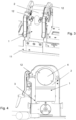
- Fig. 4 The positioning by means of the positioning element 3 in a welding machine 11 is clearly visible.
- the pipe stop 1 according to the invention is arranged between the clamping points 12 of the welding machine 11.
- the pipe stop 1 also has two stop disks 4, which are arranged on two opposite sides of the holder 2.
- the pipe stop 1 according to the invention contains adjustment elements 5 on which the stop disks 4 are arranged.
- the stop disks 4 and the adjustment elements 5 are connected to one another by means of threads 6, whereby the stop disks 4 move axially.
- the two stop disks 4 can be operated independently of one another and can therefore also be adjusted to different distances.
- Fig. 3 shows the pipe stop 1 arranged in the welding machine or briefly positioned in it in a precise position until the pipe ends or fitting ends are set to the desired length.
- the pipe stop 1 can then be easily removed from the IR butt welding machine 11.
- the figures also show that the pipe stop 1 according to the invention has locking elements 7. These serve to ensure that the stop disks 4 can be locked when they are set to the desired length of the pipe projection.
- Magnetic locks are preferably used for this purpose, although other locking devices are also conceivable. It has also proven advantageous if a scale 8 and corresponding indicators 9 are arranged on the holder 2 and the stop disks 4, which show the pipe projection length.
- the holder 1 also advantageously has recesses 10 in which the stop disks 4 are arranged.
Landscapes
- Engineering & Computer Science (AREA)
- Mechanical Engineering (AREA)
- Physics & Mathematics (AREA)
- Electromagnetism (AREA)
- Health & Medical Sciences (AREA)
- Toxicology (AREA)
- Optics & Photonics (AREA)
- Butt Welding And Welding Of Specific Article (AREA)
Abstract
Description
- Die Erfindung betrifft einen Rohranschlag zur Einstellung von Rohrüberständen von zu verschweissenden Rohren in einer Stumpfschweissmaschine, beinhaltend, einen Basis bildenden Halter, wobei der Halter ein Positionierelement zur Befestigung des Halters an einer Stumpfschweissmaschine aufweist.
- Beim Verschweissen von Rohren vorzugsweise auf IR-Stumpfschweissmaschinen werden die Rohre in gegenüberliegenden Spannstellen eingespannt und müssen einen exakten Rohrüberstand aufweisen, der dann mit dem Hobel abgehobelt wird. Zum Definieren der axialen Position der Rohrüberstände wird zwischen die Rohrenden bzw. die Spannstellen in der Schweissmaschine ein starrer Block eingelegt an den die Stirnflächen der beiden Rohrenden angestellt werden um die Rohrüberstandslängen zu definieren. Die Rohre werden festgespannt und der Block wird entfernt. Worauf mit dem Hobel die Stirnflächen überhobelt werden, wodurch immer dieselbe Länge vom Rohr abgehobelt wird, ob dies nun notwendig ist oder nicht.
- Die
EP 0 453 903 zeigt eine IR-Stumpfschweissmaschine mit einem dazwischen bringbaren Anschlag oder Anschlägen, die an den Spanneinheiten vorgesehen sind. Daraus ist gut erkennbar, dass die Rohrüberstände für jedes Rohr und jedes Fitting immer gleich ausfallen. - Nachteilig hierbei ist, dass die Überstände nicht individuell eingestellt werden können. Das heisst, das z. B. bei einem Fitting der schon sehr genau gefertigt ist, kein geringerer Rohrüberstand eingestellt werden kann, damit nur das Nötigste abgehobelt wird oder z.B. bei einer schräg verlaufenden Stirnseite um dies auszugleichen, ein längerer Rohrüberstand eingestellt werden kann, damit dieser abgetrennt wird. Wodurch unnötig viel Material verschwendet wird wie auch Zeit, wenn so viel abgetrennt werden muss, dass das Rohr mehrfach eingespannt werden muss um einen grösseren Überstand abzutrennen als mit einer Aufspannung möglich ist.
- Es ist Aufgabe der Erfindung einen Rohranschlag für eine Stumpfschweissmaschine vorzuschlagen, durch den die Längen der zu verschweissenden Rohrüberstande individuell einstellbar sind und dadurch eine Rohrverbindung wirtschaftlicher hergestellt werden kann.
- Diese Aufgabe wird erfindungsgemäss dadurch gelöst, dass der Rohranschlag zwei, an jeweils sich gegenüberliegenden Seiten des Halters, angeordnete Anschlagscheiben aufweist sowie Einstellelemente zur Einstellung der Anschlagscheiben und Arretierelemente zur Arretierung der Anschlagscheiben.
- Der erfindungsgemässe Rohranschlag zur Einstellung von Rohrüberständen von zu verschweissenden Rohren in einer Stumpfschweissmaschine vorzugsweise IR-Stumpfschweissmaschine beinhaltet einen basisbildenden Halter, wobei der Halter ein Positionierelement zur Befestigung an einer Stumpfschweissmaschine aufweist. Vorzugsweise ist das Positionierelement als Einrastelement ausgebildet um den Rohranschlag kurzfristig zum Einrichten der Rohrüberstände an der Schweissmaschine positionsgenau anzuordnen und einfach und schnell wieder zu entfernen. Dadurch ist der Rohranschlag einfach und schnell zwischen die Spannstellen einer Schweissmaschine bringbar und auch einfach und schnell wieder entfernbar. Der Rohranschlag weist zwei Anschlagscheiben auf, wobei jeweils eine Anschlagscheibe an jeweils einer der sich gegenüberliegenden Seite des Halters angeordnet ist. Zudem beinhaltet der Rohranschlag Einstellelemente zur Einstellung der Anschlagscheiben und Arretierelemente zur Arretierung der Anschlagscheiben. Durch die axial einstellbaren Anschlagscheiben wird der Rohrüberstand individuell einstellbar. Die zu verschweissenden Rohre werden an die entsprechend eingestellten Anschlagscheiben angeschlagen und dadurch wird die Länge des gewünschten Rohr- oder auch Fittingüberstands erreicht, welcher anschliessend mittels des Hobels abgehobelt wird. So kann ein ganz geringer Überstand abgehobelt werden wie auch ein langer Überstand ohne das Rohr mehrfach einspannen zu müssen.
- Die Arretierelemente sind vorzugsweise am Halter angeordnet und ragen durch den Halter hindurch auf die Anschlagscheiben.
- Vorzugsweise sind die beiden Anschlagscheiben individuell voneinander axial verfahrbar angeordnet. Die auf den beiden sich gegenüberliegenden Seiten des Halters angeordneten Anschlagscheiben sind separat voneinander einstellbar. Das heisst, dass z.B. eine Anschlagscheibe einen Millimeter mehr nach aussen axial verschoben werden kann als die andere. Vorzugsweise sind die Anschlagscheiben rotierbar und lassen sich dadurch in axialer Richtung stufenlos verschieben bzw. einstellen.
- Als vorteilhaft hat sich gezeigt, wenn die Anschlagscheiben jeweils bis zu 8mm axial vom Halter nach aussen verschoben werden können.
- Als vorteilhaft hat sich gezeigt, wenn die Anschlagscheiben mittels eines Gewindes an den Einstellelementen verstellbar angeordnet sind. Durch die Gewindeverbindung zwischen der jeweiligen Anschlagscheibe und dem Einstellelement wird eine stufenlose axiale Verschiebung der Anschlagscheiben erzielt. Entsprechend der gewünschten Anzahl von Drehungen um eine gewünschte axiale Verschiebung zu erreichen wird die Gewindesteigung gewählt, die zwischen den Anschlagscheiben und dem Einstellelement eingesetzt wird.
- Vorzugsweise ist das Einstellelement starr mit dem Halter verbunden und die Anschlagscheibe lässt sich auf dem Gewinde des Einstellelements rotieren.
- Als vorteilhaft, um eine möglichst feineinstellbare axiale Verschiebung der Anschlagscheiben zu erreichen, haben sich Feingewinde gezeigt.
- Es ist vorteilhaft wenn die Anschlagscheiben zylindrisch ausgebildet sind. Vorzugsweise weist die zylindrische Mantelfläche eine Struktur auf, wodurch sie einen besseren Gripp zum manuellen Rotieren der Anschlagscheibe aufweist.
- Als vorteilhaft hat sich gezeigt, wenn die Einstellelemente als zylinderförmige Bolzen mit einem Gewinde ausgebildet sind. Die Bolzen sind am Halter, sich abgewandt, an den sich gegenüberliegenden Seiten angeordnet.
- Als vorteilhafte Ausführung hat sich gezeigt, wenn der Halter an zwei sich gegenüberliegenden Seiten jeweils eine zylinderförmige Vertiefung aufweist. Die Vertiefung entspricht ungefähr der Grösse der Anschlagscheibe bzw. hat einen leicht grösseren Durchmesser in der die Anschlagscheibe axial verschiebbar bzw. verfahrbar angeordnet ist.
- Vorzugsweise sind die Anschlagscheiben in zylinderförmigen Vertiefungen im Halter angeordnet. Dadurch kann die axiale Position der Anschlagscheibe besser ermittelt werden.
- Als vorteilhafte Ausführung hat sich gezeigt, wenn die Arretierelemente als Magnetarretierungen ausgebildet sind. Die Arretierungen sind am Halter angeordnet, vorzugsweise auf der Höhe der Vertiefung und ragen durch eine Bohrung in der Wandung hindurch und wirken auf die Mantelflächen der Anschlagscheiben.
- Es ist vorteilhaft, wenn eine Skala zur Einstellung der axialen Position der Anschlagscheiben am Rohranschlag angeordnet ist. Vorzugsweise befindet sich die Skala an der Anschlagscheibe und korrespondierende Indikatoren am Halter oder umgekehrt um die Position der Anschlagscheibe bzw. schlussendlich die Länge des Rohrüberstands anzuzeigen.
- Als vorteilhaft hat sich gezeigt, dass der Rohranschlag symmetrisch ausgebildet ist, vorzugsweise spiegelsymmetrisch.
- Alle Ausgestaltungmöglichkeiten sind untereinander frei kombinierbar.
- Ein Ausführungsbeispiel der Erfindung wird anhand der Figuren beschrieben, wobei sich die Erfindung nicht nur auf das Ausführungsbeispiel beschränkt. Es zeigen:
- Fig. 1
- eine Explosionsdarstellung des erfindungsgemässen Rohranschlags,
- Fig. 2
- eine dreidimensionale Ansicht eines erfindungsgemässen Rohranschlags,
- Fig. 3
- einen Rohranschlag befestigt an einer Stumpfschweissmaschine und
- Fig. 4
- eine Schnittansicht durch eine Schweissmaschine mit angeordnetem Rohranschlag.
- Die in
Fig. 1 dargestellte Zeichnung zeigt eine Explosionsansicht eines erfindungsgemässen Rohranschlags 1. Der Rohranschlag 1 dient dem Einstellen von Rohrüberständen von in Stumpfschweissmaschinen eingespannten Rohren die miteinander zu verschweissen sind oder von Fittings. Der Rohranschlag 1 beinhaltet einen Halter 2 der als Basis dient. Der Halter 2 weist ein Positionierelement 3 auf, das dem einfachen Positionieren in einer Schweissmaschine 11 dient. InFig. 4 ist die Positionierung mittels des Positionierelements 3 in einer Schweissmaschine 11 gut erkennbar. Ebenfalls gut ersichtlich ist inFig. 3 , dass der erfindungsgemässe Rohranschlag 1 zwischen den Spannstellen 12 der Schweissmaschine 11 angeordnet ist. Der Rohranschlag 1 weist zudem zwei Anschlagscheiben 4 auf, die auf zwei sich gegenüberliegenden Seiten des Halters 2 angeordnet sind. Zudem beinhaltet der erfindungsgemässe Rohranschlag 1 Einstellelement 5 an denen die Anschlagscheiben 4 angeordnet sind. Die Anschlagscheiben 4 und die Einstellelemente 5 sind mittels Gewinde 6 miteinander verbunden, wodurch sich die Anschlagscheiben 4 axial verschieben. Die beiden Anschlagscheiben 4 sind unabhängig voneinander betätigbar und somit auch auf unterschiedliche Distanzen einstellbar.Fig. 3 zeigt den Rohranschlag 1 in der Schweissmaschine angeordnet bzw. kurzfristig darin positionsgenau platziert bis die Rohrenden oder Fittingsenden auf die gewünschte Länge eingestellt sind. Danach kann der Rohranschlag 1 wieder einfach aus der IR-Stumpfschweissmaschine 11 entfernt werden. In den Figuren ist zudem ersichtlich, dass der erfindungsgemässe Rohranschlag 1 Arretierungselemente 7 aufweist. Diese dienen dazu, dass wenn die Anschlagscheiben 4 auf die gewünschte Länge des Rohrüberstands eingestellt sind, sie arretiert werden können. Vorzugsweise werden dazu Magnetarretierungen verwendet, wobei auch andere Arretierungsvorrichtungen denkbar sind. Als vorteilhaft hat sich auch gezeigt, wenn eine Skala 8 und entsprechende Indikatoren 9 auf dem Halter 2 und den Anschlagscheiben 4 angeordnet sind, die die Rohrüberstandslänge anzeigen. Ebenso vorteilhaft weist die Halterung 1 Vertiefungen 10 auf in denen die Anschlagscheiben 4 angeordnet sind. -
- 1
- Rohranschlag
- 2
- Halter
- 3
- Positionierelement
- 4
- Anschlagscheibe
- 5
- Einstellelement
- 6
- Gewinde
- 7
- Arretierungselement
- 8
- Skala
- 9
- Indikator
- 10
- Vertiefung
- 11
- IR-Stumpfschweissmaschine
- 12
- Spannstelle
Claims (10)
- Rohranschlag (1) zur Einstellung von Rohrüberständen von zu verschweissenden Rohren in einer Stumpfschweissmaschine (11) beinhaltend einen Basis bildenden Halter (2), wobei der Halter (2) ein Positionierelement (3) zur Befestigung an einer Stumpfschweissmaschine (11) aufweist, dadurch gekennzeichnet dass der Rohranschlag (1) zwei, an jeweils sich gegenüberliegenden Seiten des Halters (2), angeordnete Anschlagscheiben (4) aufweist sowie Einstellelemente (5) zur Einstellung der Anschlagscheiben (4) und Arretierelemente (7) zur Arretierung der Anschlagscheiben (4).
- Rohranschlag (1) nach Anspruch 1, dadurch gekennzeichnet, dass die beiden Anschlagscheiben (4) individuell voneinander axial verfahrbar angeordnet sind.
- Rohranschlag (1) nach einem der Ansprüche 1 oder 2, dadurch gekennzeichnet, dass die Anschlagscheiben (4) mittels eines Gewindes (6) an den Einstellelementen (5) verstellbar angeordnet sind.
- Rohranschlag (1) nach einem der Ansprüche 1 bis 3, dadurch gekennzeichnet, dass die Anschlagscheiben (4) zylindrisch ausgebildet sind.
- Rohranschlag nach einem der Ansprüche 1 bis 4, dadurch gekennzeichnet, dass die Einzelelemente als zylinderförmige Bolzen mit einem Gewinde ausgebildet sind.
- Rohranschlag (1) nach einem der Ansprüche 1 bis 5, dadurch gekennzeichnet, dass der Halter (2) an zwei sich gegenüberliegenden Seiten jeweils eine zylinderförmige Vertiefung (10) aufweist.
- Rohranschlag (1) nach einem der Ansprüche 1 bis 6, dadurch gekennzeichnet, dass die Anschlagscheiben (4) in zylinderförmigen Vertiefungen (10) im Halter (2) angeordnet sind.
- Rohranschlag (1) nach einem der Ansprüche 1 bis 7, dadurch gekennzeichnet, dass die Arretierelemente (7) als Magnetarretierungen ausgebildet sind.
- Rohranschlag (1) nach einem der Ansprüche 1 bis 8, dadurch gekennzeichnet, dass eine Skala (8) zur Einstellung der axialen Position der Anschlagscheiben (4) am Rohranschlag (1) angeordnet ist.
- Rohranschlag (1) nach einem der Ansprüche 1 bis 8, dadurch gekennzeichnet, dass der Rohranschlag (1) symmetrisch ausgebildet ist.
Priority Applications (1)
| Application Number | Priority Date | Filing Date | Title |
|---|---|---|---|
| EP23175728.7A EP4467323B1 (de) | 2023-05-26 | 2023-05-26 | Einstellbarer rohranschlag |
Applications Claiming Priority (1)
| Application Number | Priority Date | Filing Date | Title |
|---|---|---|---|
| EP23175728.7A EP4467323B1 (de) | 2023-05-26 | 2023-05-26 | Einstellbarer rohranschlag |
Publications (3)
| Publication Number | Publication Date |
|---|---|
| EP4467323A1 true EP4467323A1 (de) | 2024-11-27 |
| EP4467323B1 EP4467323B1 (de) | 2026-01-21 |
| EP4467323C0 EP4467323C0 (de) | 2026-01-21 |
Family
ID=86605034
Family Applications (1)
| Application Number | Title | Priority Date | Filing Date |
|---|---|---|---|
| EP23175728.7A Active EP4467323B1 (de) | 2023-05-26 | 2023-05-26 | Einstellbarer rohranschlag |
Country Status (1)
| Country | Link |
|---|---|
| EP (1) | EP4467323B1 (de) |
Citations (2)
| Publication number | Priority date | Publication date | Assignee | Title |
|---|---|---|---|---|
| EP0453903A2 (de) | 1990-04-27 | 1991-10-30 | Georg Fischer Aktiengesellschaft | Einrichtung zum stirnseitigen Verschweissen von Kunststoffteilen |
| US5793017A (en) * | 1994-12-05 | 1998-08-11 | N.G.N. Co. Ltd. | Apparatus for automatically welding tubular components of fusible resin and pipe clamping apparatus and heating apparatus used for the same |
-
2023
- 2023-05-26 EP EP23175728.7A patent/EP4467323B1/de active Active
Patent Citations (2)
| Publication number | Priority date | Publication date | Assignee | Title |
|---|---|---|---|---|
| EP0453903A2 (de) | 1990-04-27 | 1991-10-30 | Georg Fischer Aktiengesellschaft | Einrichtung zum stirnseitigen Verschweissen von Kunststoffteilen |
| US5793017A (en) * | 1994-12-05 | 1998-08-11 | N.G.N. Co. Ltd. | Apparatus for automatically welding tubular components of fusible resin and pipe clamping apparatus and heating apparatus used for the same |
Also Published As
| Publication number | Publication date |
|---|---|
| EP4467323B1 (de) | 2026-01-21 |
| EP4467323C0 (de) | 2026-01-21 |
Similar Documents
| Publication | Publication Date | Title |
|---|---|---|
| DE102009058036B3 (de) | Spannvorrichtung für stangenförmige Profile | |
| DE3934495C1 (de) | ||
| EP0300959B1 (de) | Verfahren und Vorrichtung zum Zentrieren eines Führungsdorns | |
| EP3383580B1 (de) | Vorrichtung zum spannen mehrerer werkstücke auf einem teilapparat einer werkzeugmaschine | |
| EP4467323B1 (de) | Einstellbarer rohranschlag | |
| DE1447355B2 (de) | Vorrichtung zur schrittweisen Verstellung eines Schlittens | |
| DE102013103913A1 (de) | Spanner | |
| WO2017092975A1 (de) | Vorrichtung zum spannen mehrerer werkstücke auf einem teilapparat einer werkzeugmaschine | |
| DE3122574C1 (de) | Innenraeumwerkzeug | |
| DE102016105357B4 (de) | Vorrichtung zur Erhöhung getrennter Spannsysteme | |
| DE10023597A1 (de) | Halterungselement | |
| DE3525196A1 (de) | Schraubstock mit schnellverstellung | |
| DE19839879A1 (de) | Mehrfachaufspannvorrichtung für Werkstücke | |
| EP0033531B1 (de) | Spannbacken zum winkelgerechten Spannen von Werkstücken | |
| DE852639C (de) | Geraet zum Schraenken von Kreissaegeblaettern | |
| DE2263634C3 (de) | Werkzeug zum gleichzeitigen Bearbeiten der Flanken von Nuten | |
| DE1808050B2 (de) | Vorrichtung zum stanzen von loechern in die wandung von hohlkoerpern beliebigen querschnitts | |
| EP4227038B1 (de) | Aufspannplatte | |
| DE10017447C2 (de) | Axialantrieb | |
| DE2145524B2 (de) | Justiereinrichtung für Werkzeugmaschinen | |
| DE2412411A1 (de) | Werkzeugmaschine zur bearbeitung von metallischen bolzen | |
| DE730700C (de) | Straehler zum Schneiden wurzelartig unterschnittener und doppelgaengiger Innengewinde | |
| AT163837B (de) | Vorrichtung zum gewaltlosen Abspannen von Futtern und Spannwerkzeugen von Werkzeugmaschinen | |
| DE102022129239A1 (de) | Gewindeschneidwerkzeughalter | |
| DE202005014769U1 (de) | Fräswerkzeug |
Legal Events
| Date | Code | Title | Description |
|---|---|---|---|
| PUAI | Public reference made under article 153(3) epc to a published international application that has entered the european phase |
Free format text: ORIGINAL CODE: 0009012 |
|
| STAA | Information on the status of an ep patent application or granted ep patent |
Free format text: STATUS: THE APPLICATION HAS BEEN PUBLISHED |
|
| AK | Designated contracting states |
Kind code of ref document: A1 Designated state(s): AL AT BE BG CH CY CZ DE DK EE ES FI FR GB GR HR HU IE IS IT LI LT LU LV MC ME MK MT NL NO PL PT RO RS SE SI SK SM TR |
|
| STAA | Information on the status of an ep patent application or granted ep patent |
Free format text: STATUS: REQUEST FOR EXAMINATION WAS MADE |
|
| 17P | Request for examination filed |
Effective date: 20250516 |
|
| GRAP | Despatch of communication of intention to grant a patent |
Free format text: ORIGINAL CODE: EPIDOSNIGR1 |
|
| STAA | Information on the status of an ep patent application or granted ep patent |
Free format text: STATUS: GRANT OF PATENT IS INTENDED |
|
| RIC1 | Information provided on ipc code assigned before grant |
Ipc: B29C 65/14 20060101AFI20250728BHEP Ipc: B29C 65/20 20060101ALI20250728BHEP Ipc: B29C 65/78 20060101ALI20250728BHEP Ipc: B23K 37/053 20060101ALI20250728BHEP |
|
| INTG | Intention to grant announced |
Effective date: 20250828 |
|
| GRAS | Grant fee paid |
Free format text: ORIGINAL CODE: EPIDOSNIGR3 |
|
| GRAA | (expected) grant |
Free format text: ORIGINAL CODE: 0009210 |
|
| STAA | Information on the status of an ep patent application or granted ep patent |
Free format text: STATUS: THE PATENT HAS BEEN GRANTED |
|
| AK | Designated contracting states |
Kind code of ref document: B1 Designated state(s): AL AT BE BG CH CY CZ DE DK EE ES FI FR GB GR HR HU IE IS IT LI LT LU LV MC ME MK MT NL NO PL PT RO RS SE SI SK SM TR |
|
| REG | Reference to a national code |
Ref country code: CH Ref legal event code: F10 Free format text: ST27 STATUS EVENT CODE: U-0-0-F10-F00 (AS PROVIDED BY THE NATIONAL OFFICE) Effective date: 20260121 |
|
| REG | Reference to a national code |
Ref country code: IE Ref legal event code: FG4D Free format text: LANGUAGE OF EP DOCUMENT: GERMAN |
|
| U01 | Request for unitary effect filed |
Effective date: 20260121 |
|
| U07 | Unitary effect registered |
Designated state(s): AT BE BG DE DK EE FI FR IT LT LU LV MT NL PT RO SE SI Effective date: 20260127 |