EP4466419B1 - Abdeckungsvorrichtung und verfahren zur montage einer abdeckungsvorrichtung an einem dachfenster - Google Patents
Abdeckungsvorrichtung und verfahren zur montage einer abdeckungsvorrichtung an einem dachfenster Download PDFInfo
- Publication number
- EP4466419B1 EP4466419B1 EP23719289.3A EP23719289A EP4466419B1 EP 4466419 B1 EP4466419 B1 EP 4466419B1 EP 23719289 A EP23719289 A EP 23719289A EP 4466419 B1 EP4466419 B1 EP 4466419B1
- Authority
- EP
- European Patent Office
- Prior art keywords
- frame
- flashing
- sealing
- flashing device
- sealing portion
- Prior art date
- Legal status (The legal status is an assumption and is not a legal conclusion. Google has not performed a legal analysis and makes no representation as to the accuracy of the status listed.)
- Active
Links
Images


Classifications
-
- E—FIXED CONSTRUCTIONS
- E04—BUILDING
- E04D—ROOF COVERINGS; SKY-LIGHTS; GUTTERS; ROOF-WORKING TOOLS
- E04D13/00—Special arrangements or devices in connection with roof coverings; Protection against birds; Roof drainage ; Sky-lights
- E04D13/02—Roof-covering aspects of dormer windows
-
- E—FIXED CONSTRUCTIONS
- E04—BUILDING
- E04D—ROOF COVERINGS; SKY-LIGHTS; GUTTERS; ROOF-WORKING TOOLS
- E04D13/00—Special arrangements or devices in connection with roof coverings; Protection against birds; Roof drainage ; Sky-lights
- E04D13/03—Sky-lights; Domes; Ventilating sky-lights
- E04D13/0305—Supports or connecting means for sky-lights of flat or domed shape
- E04D13/031—Supports or connecting means for sky-lights of flat or domed shape characterised by a frame for connection to an inclined roof
-
- E—FIXED CONSTRUCTIONS
- E04—BUILDING
- E04D—ROOF COVERINGS; SKY-LIGHTS; GUTTERS; ROOF-WORKING TOOLS
- E04D13/00—Special arrangements or devices in connection with roof coverings; Protection against birds; Roof drainage ; Sky-lights
- E04D13/14—Junctions of roof sheathings to chimneys or other parts extending above the roof
- E04D13/147—Junctions of roof sheathings to chimneys or other parts extending above the roof specially adapted for inclined roofs
- E04D13/1473—Junctions of roof sheathings to chimneys or other parts extending above the roof specially adapted for inclined roofs specially adapted to the cross-section of the parts extending above the roof
- E04D13/1475—Junctions of roof sheathings to chimneys or other parts extending above the roof specially adapted for inclined roofs specially adapted to the cross-section of the parts extending above the roof wherein the parts extending above the roof have a generally rectangular cross-section
-
- E—FIXED CONSTRUCTIONS
- E04—BUILDING
- E04D—ROOF COVERINGS; SKY-LIGHTS; GUTTERS; ROOF-WORKING TOOLS
- E04D13/00—Special arrangements or devices in connection with roof coverings; Protection against birds; Roof drainage ; Sky-lights
- E04D13/03—Sky-lights; Domes; Ventilating sky-lights
- E04D13/035—Sky-lights; Domes; Ventilating sky-lights characterised by having movable parts
- E04D13/0351—Sky-lights; Domes; Ventilating sky-lights characterised by having movable parts the parts pivoting about a fixed axis
- E04D13/0354—Sky-lights; Domes; Ventilating sky-lights characterised by having movable parts the parts pivoting about a fixed axis the parts being flat
Definitions
- the present invention relates to a flashing device for a roof window comprising a frame and mounted in a roof structure, said flashing device comprising a first flashing member and a second flashing member both extending in a length direction, and two sealing members arranged at opposite ends of the flashing device seen in the length direction, where an upwards portion of the first flashing member and a downwards portion of the second flashing members are interconnected in sliding engagement allowing the relative position between the first and second flashing members to be adjusted during mounting of the flashing device, where the first flashing member further comprises a outward portion extending at an angle in relation to the upwards portion and being configured for extending over the roof structure away from the roof window, where the second flashing member further comprises an inward portion extending at an angle in relation to the downward portion and being configured for engagement with the frame of the roof window, and where each sealing member includes a first sealing portion and a second sealing portion, said first sealing portion being positioned substantially in parallel with the inward portion and said second sealing portion being positioned substantially in parallel with the downward
- the joint between the roof window and the roof structure is covered by a covering assembly including flashing and cladding members and devices.
- a covering assembly including flashing and cladding members and devices.
- a flashing device of the type mentioned above comprising a sealing member is known from the applicant's prior patent application WO2004/051026A1 and has been in successful use for many years, but new types of roof windows and an increase in the use of roof window in roof with low pitches has prompted a desire for further development.
- the sealing member comprises at least one frame attachment portion configured for attachment of the sealing member to the frame of the roof window.
- the sealing member not only contributes to weather-proofing the flashing device itself, as was the case in WO2004/051026A1 , but also contributes to establishing a connection between the flashing device and frame of the roof window.
- the connection has a built-in sealing function due to being incorporated in the sealing member, the need for subsequently sealing joints using for example a silicone-based joint filler, as is commonly seen with many prior art roof windows, may be reduced.
- a flashing device of this type is particularly well suited for use at the bottom of a roof window mounted in an inclined roof structure, where the sliding engagement between the flashing members allows an adaptation to different angles of inclination of the roof structure.
- the flashing device being mounted at a bottom frame member of the frame of the roof window. It is, however, to be understood that the invention is not limited to this use.
- the sealing member is substantially L-shaped.
- the sealing member is preferably made from a resilient material, preferably an elastomer, such as ethylene propylene diene monomer (EDPM).
- EDPM ethylene propylene diene monomer
- the at least one frame attachment portion comprises a flange extending from the first sealing portion and being configured for sliding engagement with a groove in the frame.
- said flange is brought into a groove in the frame as the flashing device is displaced relative to the frame.
- the displacement may be substantially perpendicular to the frame plane defined by the frame members of the frame, but it is presently considered advantageous to bring the flashing device into contact with the frame by displacing it in a direction parallel to the frame plane, i.e. in a direction substantially perpendicular to the upwards and downwards portions and to the length direction of the flashing device.
- the flashing device may be arranged underneath another part of the roof window or to be slid into engagement with a flashing member or a cover member. If the flashing device is mounted at a bottom frame member with the length direction of the flashing device extending in parallel to the length direction of the bottom frame member, the displacement is preferably perpendicular to the length direction of the bottom frame member.
- the flange comprises a first flange leg extending from the first sealing portion away from the second sealing portion and a second flange leg extending substantially perpendicular to the first flange leg and substantially in parallel with the first sealing portion, the flange thus having an L-shape.
- This will for example allow the second flange leg to be arranged in a groove extending substantially parallel to the first sealing portion at a distance from it, and/or a fixation of the sealing member in two directions.
- the flange has a length direction extending substantially perpendicular to the length direction of the flashing device and that the flashing device is mounted by displacement in a direction substantially parallel to the inward portion and perpendicular to the length direction.
- the flange may be brought into engagement with a groove in an interface unit of/on the frame, said interface unit for example including an extruded profile made from a metal, such as aluminium, or a dimensionally stable polymer, such as a thermoplastic elastomer, for example polyvinylchloride or polypropylene, possibly reinforced by fibres, such as glass fibres.
- a metal such as aluminium
- a dimensionally stable polymer such as a thermoplastic elastomer, for example polyvinylchloride or polypropylene, possibly reinforced by fibres, such as glass fibres.
- the at least one frame attachment portion may comprise a fastener guiding section configured for guiding a fastener used for securing the sealing member to the frame.
- a fastener can be inserted in the fastener guiding section and driven into the frame, the fastener guiding section ensuring that the fastener penetrates into the frame or an interface unit thereon at the correct position and at the same time sealing the joint between the fastener and the frame.
- the fastener guiding section extends substantially in parallel with the first sealing portion and substantially perpendicular to the second sealing portion, thus guiding the fastener in a direction, which is substantially parallel to the frame plane and perpendicular to the frame member at which the flashing device is mounted.
- the fastener guiding section extends from an opening in the second sealing portion and through the first sealing portion.
- the sealing members are located at the ends of the flashing device in the length direction thereof, the fastener may be driven into the ends of the frame members extending perpendicular to frame member along which the flashing device extends in the mounted state, i.e. the side frame members when the flashing device is used at the bottom frame member of a roof window.
- the fasteners need not be driven into the actual frame members.
- the frame it is also possible for the frame to include an interface unit for engagement with other parts of the roof window and such an interface unit may be used for receiving the fasteners.
- the second flashing member may comprise a hole positioned in continuation of the fastener guiding section, such that a fastener guided by the fastener guiding section projects through said hole.
- the sealing member may further comprise a support projection supporting the inward portion of the second flashing member and forming a sealing connection therewith.
- sealing member may comprise one or more of the following:
- a second aspect of the invention relates to a method of mounting a flashing device at a roof window comprising a frame and mounted in a roof structure, comprising the following steps:
- the reference to the flashing device does not have to be in direct engagement with an outer side of the frame of the roof window. It may also be in engagement with insulating material, such as an insulating frame arrange around the frame, or with other items related to the installation or operation of the roof window, such as a motor enclosure.
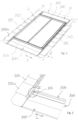
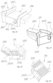
- a roof window 1 is shown with a covering assembly 10, where the right-hand side of the top flashing member 1011 is shown in a state of delivery, before adaptation to the shape of a roofing material used alongside the roof window.
- the roof window 1 is shown in an inclined position as it is intended for being mounted in an inclined roof structure.
- the covering assembly comprises a plurality of side flashing members 1012, 1013, a bottom flashing device 1014 and a plurality of cladding members 1021, 1022, 1023, 1024 each covering a part of the sash carrying the pane element 4.
- the roof window 1 comprises a frame (not visible in Fig. 1 ), and the top flashing member 1011, the side flashing members 1012, 1013, and the bottom flashing device 1014 extend in a respective length direction L along top, side and frame members, respectively. Together the frame members define a frame opening covered by the pane element 4 and a frame plane F.
- the bottom flashing device 1014 is shown in more detail in Fig. 2 corresponding to the lower left-hand side of Fig. 1 , but showing only the flashing members and the flashing device.
- the bottom flashing device comprises a first flashing member 1015 and a second flashing member 1016 both extending in a length direction L of the flashing device and being interconnected in sliding engagement allowing the relative position between the first and second flashing members to be adjusted in a height direction perpendicular to the frame plane F during mounting of the flashing device.
- the first flashing member 1015 comprises an outward portion 1015o being configured for extending over the roof structure away from the roof window and an upwards portion 1015u extending at an angle in relation to the outward portion and being configured for extending up along and outer side of the frame of the roof window.
- the upwards portion 1015u is connected to a downwards portion 1016d of the second flashing members 1016 configured for extending down along the outer side of the frame of the roof window
- the second flashing member further comprises an inward portion 1016i extending at an angle in relation to the downward portion and being configured for engagement with an exterior side of the frame of the roof window.
- the upwards portion 1015u and the downwards portion 1016d both have bent edges 1015e, 1016e embracing each other in the mounted state as shown in Fig. 5 and Fig. 6 and allowing a telescopic mutual movement both in the length direction L and in a height direction perpendicular to the frame plane F.
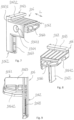
- Fig. 5 and Fig. 6 also show that a sealing member 106 is arranged at the end of the flashing device and it is to be understood that a similar sealing member is found at the opposition end of the flashing device 1014.
- Each sealing member 106 includes at least one first sealing portion 1061 positioned substantially in parallel with the inward portion 1016i and a second sealing portion 1062 positioned substantially in parallel with the downward portion 1016d, giving the sealing member an L-shape.
- the sealing member further comprises two frame attachment portions 1063, 1064 configured for attachment of the sealing member to the frame of the roof window.
- a first frame attachment portion in the form of a flange 1063 extends from the first sealing portion 1061 and comprises a first flange leg 10631 extending from the first sealing portion away from the second sealing portion 1062 and a second flange leg 10632 extending substantially perpendicular to the first flange leg and substantially in parallel with the first sealing portion.
- the flange 1063 extends perpendicular to the length direction L of the flashing device 1014 in the mounted state and engages with a flange 1017 of lowermost side flashing member 1013a.
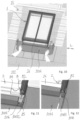
- the mounting of the covering assembly starts with the mounting of the bottom flashing device 1014 and it is displaced in a direction parallel to the frame plane F and perpendicular to the length direction L of the bottom frame member 24.
- the first frame attachment portion 1063 comes into engagement with a side element 82 of an interface unit 8 as shown in Fig. 11 , by the first flange leg 10631 sliding into a groove 85 in the side element 82.
- FIG. 2-6 shown the left-hand side of the roof window as seen in Fig. 1
- the Fig. 11 and 12 show the right-hand side. It is to be understood that the two sides are identical, except for being mirror inverted and that the sealing member used at the right-hand side is also mirror inverted in relation to that shown in Fig. 7-9 .
- the second frame attachment portion in the form of a fastener guiding section 1064 is configured for guiding a fastener 1065 used for securing the sealing member to the frame as shown in Fig. 12 .
- the fastener guiding section extends from an opening 10641 in the second sealing portion 1062 and through the first sealing portion 1061 in a direction substantially in parallel with the first sealing portion and substantially perpendicular to the second sealing portion.
- the fastener 2065 is a screw, which is driven into a bottom element 84 of the interface unit 8, said bottom element being seen in Fig. 11 , where the bottom flashing device is not yet in its mounted position.
- the second flashing member 1016 in this embodiment comprises a hole 10161 in the downwards portion 1016d and in the assembled state of the bottom flashing device 1014 shown in Fig. 1 and Fig. 2 , this hole is positioned in continuation.
- the fastener 1065 When the fastener 1065 is inserted into the fastener guiding section it will project through said hole and the bottom flashing device will thus only be attached indirectly to the frame of the roof window via the connection to the sealing member attached thereto but also directly by the engagement with the fastener.
- frame attachment portions 1063, 1064 have here been described as being attached to a side element 82 and a bottom element 84 of an interface unit, it is to be understood that such a unit need not be present and that the frame attachment portions may instead be used for attachment directly to a traditional frame member.
- the sealing member 106 further comprises a support projection 1066 forming part of the first sealing portion 1061 and supporting and sealing against the inward portion 1016i as shown in Fig. 5 .
- the sealing member 106 further comprises guiding surfaces 1067 on the second sealing portion 1062 for engagement with an extended section 10162 of the second flashing element 1016 during assembly, and an opening 1068 in the second sealing portion accommodating the extended section in the assembled state.
- both the first sealing portion 1061 and the second sealing portion 1062 comprises ribs for preventing full surface contact with the second flashing member 1016.
- FIG. 13-21 An alternative embodiment of the sealing member 106 and the flashing device is shown in Fig. 13-21 , where Fig. 13-16 correspond to Fig. 3-6 and Fig. 17-20 show the sealing member from different angles.
- the sealing member 106 in Fig. 13-21 differs from that described above in that second sealing portion is shorter and does neither extend into contact with second flashing member 1015 as shown in Fig. 6 nor comprises the opening 1068 for accommodating an extended section of the second flashing element. Instead that sealing member rides on the second flashing member 1016 engaging with a recess 10163 in the second flashing member.
- the sealing member 106 comprises a sealing lip 1069 engaging with a part 10151 of the second flashing member 1015 projecting along a side member of the frame of the roof window. Such a lip may also be added to the sealing member in Fig. 7-9 .
- FIG. 21-24 A further alternative embodiment of the sealing member 106 is shown in Fig. 21-24 .
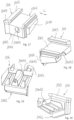
- the bottom element 84 of the interface unit is seen in Fig. 25 and shown alone in Fig. 26 .
- the bottom element 84 comprises a fastener guiding section 841 with an opening 842.
- the fastener guiding section 841 fits into the recess 10642 in the bottom of the sealing member seen in Fig.
- the fastener guiding section 1064 of the sealing member is relatively short, but it is to be understood that it may be longer and that the fastener guiding section 841 in the bottom element will then be correspondingly shorter.
- the sealing member 106 shown in Fig. 17-20 may also be used on a one-part bottom flashing member, not only on a two-part flashing device. This allows the use of the same sealing member on several different roof windows, and or in combination with several different covering assemblies 10 designed for example for different installation depths of the roof window in the roof structure.
- each component may in principle be reused, be recycled by appropriate environmentally responsible disposal means, or the material be recovered for other uses.
Landscapes
- Engineering & Computer Science (AREA)
- Architecture (AREA)
- Civil Engineering (AREA)
- Structural Engineering (AREA)
- Specific Sealing Or Ventilating Devices For Doors And Windows (AREA)
- Arrangement Of Elements, Cooling, Sealing, Or The Like Of Lighting Devices (AREA)
- Seal Device For Vehicle (AREA)
- Roof Covering Using Slabs Or Stiff Sheets (AREA)
Claims (11)
- Dachabschlussvorrichtung (1014) für ein Dachfenster (1), das einen Rahmen umfasst und in einer Dachstruktur montiert ist, wobei die Dachabschlussvorrichtung ein erstes Dachabschlussglied (1015) und ein zweites Dachabschlussglied (1016), die sich beide in einer Längenrichtung (L) der Dachabschlussvorrichtung erstrecken, sowie zwei Dichtungsglieder (106) umfasst, die, in der Längenrichtung gesehen, an gegenüberliegenden Enden der Dachabschlussvorrichtung angeordnet sind, wobei ein aufwärtiger Abschnitt des ersten Dachabschlussglieds und ein abwärtiger Abschnitt des zweiten Dachabschlussglieds in Gleiteingriff miteinander verbunden sind, dank dessen die relative Position zwischen dem ersten und dem zweiten Dachabschlussglied während der Montage der Dachabschlussvorrichtung verstellt werden kann, wobei das erste Dachabschlussglied ferner einen nach außen gehenden Abschnitt umfasst, der sich in einem Winkel bezüglich des aufwärtigen Abschnitts erstreckt und dazu ausgestaltet ist, sich über die Dachstruktur von dem Dachfenster weg zu erstrecken, wobei das zweite Dachabschlussglied (1016) ferner einen nach innen gehenden Abschnitt umfasst, der sich in einem Winkel bezüglich des abwärtigen Abschnitts erstreckt und zum Eingriff mit dem Rahmen des Dachfensters ausgestaltet ist, und wobei jedes Dichtungsglied (106) einen ersten Dichtungsabschnitt (1061) und einen zweiten Dichtungsabschnitt (1062) aufweist, wobei der erste Dichtungsabschnitt (1061) im Wesentlichen parallel zu dem nach innen gehenden Abschnitt positioniert ist und der zweite Dichtungsabschnitt (1062) im Wesentlichen parallel zu dem abwärtigen Abschnitt positioniert ist, dadurch gekennzeichnet, dass jedes Dichtungsglied (106) ferner mindestens einen Rahmenanbringabschnitt (1063) umfasst, der zum Anbringen des Dichtungsglieds an dem Rahmen des Dachfensters ausgestaltet ist, wobei der mindestens eine Rahmenanbringabschnitt einen Flansch umfasst, der sich von dem ersten Dichtungsabschnitt erstreckt und für den Gleiteingriff mit einer Nut in dem Rahmen ausgestaltet ist, und wobei der Flansch einen ersten Flanschschenkel (10631), der sich von dem ersten Dichtungsabschnitt und von dem zweiten Dichtungsabschnitt weg erstreckt, und einen zweiten Flanschschenkel (10632) umfasst, der sich im Wesentlichen senkrecht zu dem ersten Flanschschenkel und im Wesentlichen parallel zu dem ersten Dichtungsabschnitt erstreckt.
- Dachabschlussvorrichtung nach einem oder mehreren der vorhergehenden Ansprüche, wobei der mindestens eine Rahmenanbringabschnitt einen Befestigungselement-Führungsabschnitt umfasst, der zum Führen eines Befestigungselements ausgestaltet ist, das zum Befestigen des Dichtungsglieds an dem Rahmen dient.
- Dachabschlussvorrichtung nach Anspruch 2, wobei sich der Befestigungselement-Führungsabschnitt im Wesentlichen parallel zu dem ersten Dichtungsabschnitt und im Wesentlichen senkrecht zu dem zweiten Dichtungsabschnitt erstreckt.
- Dachabschlussvorrichtung nach Anspruch 2 oder 3, wobei sich der Befestigungselement-Führungsabschnitt von einer Öffnung in dem zweiten Dichtungsabschnitt und durch den ersten Dichtungsabschnitt erstreckt.
- Dachabschlussvorrichtung nach einem oder mehreren der Ansprüche 2 - 4, wobei das zweite Dachabschlussglied ein in der Fortsetzung des Befestigungselement-Führungsabschnitts positioniertes Loch umfasst, so dass ein von dem Befestigungselement-Führungsabschnitt geführtes Befestigungselement durch das Loch vorragt.
- Verfahren zum Montieren einer Dachabschlussvorrichtung (1014) an einem Dachfenster (1), das einen Rahmen umfasst und in einer Dachstruktur montiert ist, wobei das Verfahren die folgenden Schritte umfasst:A) Bereitstellen einer Dachabschlussvorrichtung nach einem oder mehreren der Ansprüche 1 - 5,B) Anordnen der Dachabschlussvorrichtung an der Dachstruktur und an einer Außenseite des Rahmens des Dachfensters, die von einer durch den Rahmen definierten Rahmenöffnung weg weist,C) Verbinden des Dichtungsglieds mit dem Rahmen unter Verwendung von mindestens einem Rahmenanbringabschnitt.
- Verfahren nach Anspruch 6, wobei die Dachabschlussvorrichtung während Schritt B) mit der Außenseite des Rahmens in Eingriff gebracht wird, indem die Dachabschlussvorrichtung in einer im Wesentlichen senkrecht zu dem aufwärtigen und dem abwärtigen Abschnitt verlaufenden Richtung verschoben wird.
- Verfahren nach Anspruch 6 oder 7, wobei ein sich von dem ersten Dichtungsabschnitt des Rahmenanbringabschnitts erstreckender Flansch während Schritt C) durch eine Gleitbewegung in Eingriff mit einer Nut in dem Rahmen gebracht wird.
- Verfahren nach Anspruch 8, wobei der Flansch mit einer Nut in einer Schnittstelleneinheit des Rahmens in Eingriff gebracht wird.
- Verfahren nach einem oder mehreren von Ansprüchen 6 - 9, wobei ein Befestigungselement während Schritt C) in einen Befestigungselement-Führungsabschnitt des Rahmenanbringabschnitts und in den Rahmen eingeführt wird.
- Verfahren nach Anspruch 10, wobei das Befestigungselement durch ein Loch in dem zweiten Dachabschlussglied eingeführt wird.
Applications Claiming Priority (2)
| Application Number | Priority Date | Filing Date | Title |
|---|---|---|---|
| DKPA202270172A DK181526B1 (en) | 2022-03-31 | 2022-03-31 | A covering device and a method for mounting a covering device at a skylight |
| PCT/DK2023/050086 WO2023186249A1 (en) | 2022-03-31 | 2023-03-31 | A flashing device and a method of mounting a flashing device at a roof window |
Publications (3)
| Publication Number | Publication Date |
|---|---|
| EP4466419A1 EP4466419A1 (de) | 2024-11-27 |
| EP4466419B1 true EP4466419B1 (de) | 2025-06-18 |
| EP4466419C0 EP4466419C0 (de) | 2025-06-18 |
Family
ID=86185045
Family Applications (1)
| Application Number | Title | Priority Date | Filing Date |
|---|---|---|---|
| EP23719289.3A Active EP4466419B1 (de) | 2022-03-31 | 2023-03-31 | Abdeckungsvorrichtung und verfahren zur montage einer abdeckungsvorrichtung an einem dachfenster |
Country Status (7)
| Country | Link |
|---|---|
| US (1) | US12486669B2 (de) |
| EP (1) | EP4466419B1 (de) |
| CN (1) | CN119053759B (de) |
| DK (1) | DK181526B1 (de) |
| HU (1) | HUE072333T2 (de) |
| PL (1) | PL4466419T3 (de) |
| WO (1) | WO2023186249A1 (de) |
Family Cites Families (13)
| Publication number | Priority date | Publication date | Assignee | Title |
|---|---|---|---|---|
| DE60138814D1 (de) * | 2000-08-21 | 2009-07-09 | Vkr Holding As | Schwenkbarer dachanschlussstreifen und ein dachanschlussatz |
| CZ20031445A3 (cs) * | 2000-11-25 | 2003-11-12 | Vkr Holding A/S | Lemovací prvek pro konstrukci pronikající střechou a lemovací souprava |
| ATE323807T1 (de) * | 2002-11-29 | 2006-05-15 | Vkr Holding As | Kehlblechvorrichtung und verfahren zur installierung einer eindach durchdringenden konstruktion mittels der kehlblechvorrichtung |
| CN2701951Y (zh) * | 2003-11-21 | 2005-05-25 | Vkr控股公司 | 斜屋顶窗罩板密封件 |
| US20140318049A1 (en) * | 2011-04-14 | 2014-10-30 | A. Raymond Et Cie | Connector for hollow portions of profile member(s), particularly for double-pane window frames |
| US8869462B2 (en) * | 2012-06-15 | 2014-10-28 | RussCo57, LLP | Termination pocket for deck |
| DK179229B1 (en) * | 2015-11-24 | 2018-02-19 | Vkr Holding As | A sealing member for use between a flashing member and a roofing material, a flashing kit including such a sealing member, and a method for weather proofing the joint between a roof of a building and a roof penetrating structure |
| DE202018006624U1 (de) * | 2017-09-11 | 2021-08-18 | Vkr Holding A/S | Windschutzpolster und Kit, das mehrere Windschutzpolster und eine Dichtungsmanschette zur Verwendung bei der Installation eines Fensterrahmens umfasst |
| DK179824B1 (en) * | 2017-12-27 | 2019-07-15 | Vkr Holding A/S | A method for interconnecting flashing members and a flashing element with a seam |
| DK180344B1 (en) * | 2019-01-10 | 2021-01-15 | Vkr Holding As | A middle flashing assembly and a method for weather-proofing a roof window arrangement |
| US11002016B2 (en) * | 2019-01-10 | 2021-05-11 | Vkr Holding A/S | Connector element for a flashing assembly for use in a roof window arrangement, and a method for weather proofing a roof window arrangement |
| DK180351B1 (en) * | 2019-01-10 | 2021-01-22 | Vkr Holding As | An end closure for a cladding for a roof window and a roof window arrangement |
| DK180960B1 (en) * | 2019-12-05 | 2022-08-11 | Vkr Holding As | A sealing gasket for use between flashing members, a flashing arrangement for a roof window including at least two flashing members and at least one sealing gasket, and method of sealing a gap between flashing members for a roof window |
-
2022
- 2022-03-31 DK DKPA202270172A patent/DK181526B1/en active IP Right Grant
-
2023
- 2023-03-31 EP EP23719289.3A patent/EP4466419B1/de active Active
- 2023-03-31 WO PCT/DK2023/050086 patent/WO2023186249A1/en not_active Ceased
- 2023-03-31 CN CN202380031240.5A patent/CN119053759B/zh active Active
- 2023-03-31 HU HUE23719289A patent/HUE072333T2/hu unknown
- 2023-03-31 US US18/849,489 patent/US12486669B2/en active Active
- 2023-03-31 PL PL23719289.3T patent/PL4466419T3/pl unknown
Also Published As
| Publication number | Publication date |
|---|---|
| PL4466419T3 (pl) | 2025-09-01 |
| WO2023186249A1 (en) | 2023-10-05 |
| DK202270172A1 (en) | 2024-02-08 |
| CN119053759B (zh) | 2025-06-17 |
| EP4466419A1 (de) | 2024-11-27 |
| CN119053759A (zh) | 2024-11-29 |
| US12486669B2 (en) | 2025-12-02 |
| HUE072333T2 (hu) | 2025-11-28 |
| US20250109593A1 (en) | 2025-04-03 |
| DK181526B1 (en) | 2024-04-05 |
| EP4466419C0 (de) | 2025-06-18 |
Similar Documents
| Publication | Publication Date | Title |
|---|---|---|
| US7331145B2 (en) | Flashing component for a roof window assembly | |
| KR101355881B1 (ko) | 태양전지 모듈의 고정구조, 태양전지 모듈용의 프레임 및 고정부재 | |
| US5199234A (en) | Skylight assembly | |
| US4930275A (en) | Skylight assembly | |
| HUT77496A (hu) | Építőelem és eljárás az építőelem felszerelésére | |
| DK201370486A1 (en) | A connector element for use in a flashing assembly for roof windows mounted side-by-side and a method for mounting a flashing assembly | |
| US11078671B2 (en) | Middle flashing assembly and a method for weather-proofing a roof window arrangement | |
| EP4466419B1 (de) | Abdeckungsvorrichtung und verfahren zur montage einer abdeckungsvorrichtung an einem dachfenster | |
| CN100439629C (zh) | 防水板装置以及通过防水板装置安装屋顶贯穿结构的方法 | |
| KR20010013486A (ko) | 건축물의 벽면에 패널을 부착하는 구조물 | |
| JP3944843B2 (ja) | 改装窓 | |
| US20060048461A1 (en) | Connectors for roofs | |
| US7698857B2 (en) | Roof assembly method and apparatus | |
| JP7836749B2 (ja) | 太陽光パネル架台及び太陽光発電屋根 | |
| CN216196120U (zh) | 光伏建筑一体屋面用支架 | |
| JPH072879Y2 (ja) | 補助組立建物の角度可変屋根の取付装置 | |
| EP4499943A1 (de) | Dachfenster und verfahren zur montage eines dachfensters | |
| JPH0453385Y2 (de) | ||
| JP2618505B2 (ja) | 屋根の防水構造 | |
| KR20190022018A (ko) | 코너후레싱 캡형 고정장치 및 외장판넬 보강방법 | |
| JP2555923Y2 (ja) | 採光用天窓の水切構造 | |
| JPH10299147A (ja) | 簡易屋根 | |
| JPH108678A (ja) | バルコニー笠木の取着構造 | |
| JPH10169043A (ja) | 開口付外壁パネル | |
| JPH04143354A (ja) | パラペットの防水処理構造 |
Legal Events
| Date | Code | Title | Description |
|---|---|---|---|
| STAA | Information on the status of an ep patent application or granted ep patent |
Free format text: STATUS: UNKNOWN |
|
| STAA | Information on the status of an ep patent application or granted ep patent |
Free format text: STATUS: THE INTERNATIONAL PUBLICATION HAS BEEN MADE |
|
| PUAI | Public reference made under article 153(3) epc to a published international application that has entered the european phase |
Free format text: ORIGINAL CODE: 0009012 |
|
| STAA | Information on the status of an ep patent application or granted ep patent |
Free format text: STATUS: REQUEST FOR EXAMINATION WAS MADE |
|
| 17P | Request for examination filed |
Effective date: 20240822 |
|
| AK | Designated contracting states |
Kind code of ref document: A1 Designated state(s): AL AT BE BG CH CY CZ DE DK EE ES FI FR GB GR HR HU IE IS IT LI LT LU LV MC ME MK MT NL NO PL PT RO RS SE SI SK SM TR |
|
| GRAP | Despatch of communication of intention to grant a patent |
Free format text: ORIGINAL CODE: EPIDOSNIGR1 |
|
| STAA | Information on the status of an ep patent application or granted ep patent |
Free format text: STATUS: GRANT OF PATENT IS INTENDED |
|
| INTG | Intention to grant announced |
Effective date: 20250205 |
|
| GRAS | Grant fee paid |
Free format text: ORIGINAL CODE: EPIDOSNIGR3 |
|
| GRAA | (expected) grant |
Free format text: ORIGINAL CODE: 0009210 |
|
| STAA | Information on the status of an ep patent application or granted ep patent |
Free format text: STATUS: THE PATENT HAS BEEN GRANTED |
|
| AK | Designated contracting states |
Kind code of ref document: B1 Designated state(s): AL AT BE BG CH CY CZ DE DK EE ES FI FR GB GR HR HU IE IS IT LI LT LU LV MC ME MK MT NL NO PL PT RO RS SE SI SK SM TR |
|
| DAV | Request for validation of the european patent (deleted) | ||
| DAX | Request for extension of the european patent (deleted) | ||
| REG | Reference to a national code |
Ref country code: GB Ref legal event code: FG4D |
|
| REG | Reference to a national code |
Ref country code: CH Ref legal event code: EP |
|
| REG | Reference to a national code |
Ref country code: DE Ref legal event code: R096 Ref document number: 602023004126 Country of ref document: DE |
|
| REG | Reference to a national code |
Ref country code: CH Ref legal event code: EP |
|
| REG | Reference to a national code |
Ref country code: IE Ref legal event code: FG4D |
|
| U01 | Request for unitary effect filed |
Effective date: 20250618 |
|
| U07 | Unitary effect registered |
Designated state(s): AT BE BG DE DK EE FI FR IT LT LU LV MT NL PT RO SE SI Effective date: 20250627 |
|
| PG25 | Lapsed in a contracting state [announced via postgrant information from national office to epo] |
Ref country code: GR Free format text: LAPSE BECAUSE OF FAILURE TO SUBMIT A TRANSLATION OF THE DESCRIPTION OR TO PAY THE FEE WITHIN THE PRESCRIBED TIME-LIMIT Effective date: 20250919 Ref country code: NO Free format text: LAPSE BECAUSE OF FAILURE TO SUBMIT A TRANSLATION OF THE DESCRIPTION OR TO PAY THE FEE WITHIN THE PRESCRIBED TIME-LIMIT Effective date: 20250918 |
|
| PG25 | Lapsed in a contracting state [announced via postgrant information from national office to epo] |
Ref country code: HR Free format text: LAPSE BECAUSE OF FAILURE TO SUBMIT A TRANSLATION OF THE DESCRIPTION OR TO PAY THE FEE WITHIN THE PRESCRIBED TIME-LIMIT Effective date: 20250618 |
|
| PG25 | Lapsed in a contracting state [announced via postgrant information from national office to epo] |
Ref country code: RS Free format text: LAPSE BECAUSE OF FAILURE TO SUBMIT A TRANSLATION OF THE DESCRIPTION OR TO PAY THE FEE WITHIN THE PRESCRIBED TIME-LIMIT Effective date: 20250918 |
|
| REG | Reference to a national code |
Ref country code: HU Ref legal event code: AG4A Ref document number: E072333 Country of ref document: HU |
|
| PG25 | Lapsed in a contracting state [announced via postgrant information from national office to epo] |
Ref country code: IS Free format text: LAPSE BECAUSE OF FAILURE TO SUBMIT A TRANSLATION OF THE DESCRIPTION OR TO PAY THE FEE WITHIN THE PRESCRIBED TIME-LIMIT Effective date: 20251018 |
|
| PG25 | Lapsed in a contracting state [announced via postgrant information from national office to epo] |
Ref country code: SM Free format text: LAPSE BECAUSE OF FAILURE TO SUBMIT A TRANSLATION OF THE DESCRIPTION OR TO PAY THE FEE WITHIN THE PRESCRIBED TIME-LIMIT Effective date: 20250618 |
|
| PG25 | Lapsed in a contracting state [announced via postgrant information from national office to epo] |
Ref country code: SK Free format text: LAPSE BECAUSE OF FAILURE TO SUBMIT A TRANSLATION OF THE DESCRIPTION OR TO PAY THE FEE WITHIN THE PRESCRIBED TIME-LIMIT Effective date: 20250618 |
|
| PG25 | Lapsed in a contracting state [announced via postgrant information from national office to epo] |
Ref country code: ES Free format text: LAPSE BECAUSE OF FAILURE TO SUBMIT A TRANSLATION OF THE DESCRIPTION OR TO PAY THE FEE WITHIN THE PRESCRIBED TIME-LIMIT Effective date: 20250618 |
|
| U20 | Renewal fee for the european patent with unitary effect paid |
Year of fee payment: 4 Effective date: 20260209 |
|
| REG | Reference to a national code |
Ref country code: CH Ref legal event code: U11 Free format text: ST27 STATUS EVENT CODE: U-0-0-U10-U11 (AS PROVIDED BY THE NATIONAL OFFICE) Effective date: 20260401 |
|
| PGFP | Annual fee paid to national office [announced via postgrant information from national office to epo] |
Ref country code: HU Payment date: 20260303 Year of fee payment: 4 |
|
| PLBE | No opposition filed within time limit |
Free format text: ORIGINAL CODE: 0009261 |
|
| STAA | Information on the status of an ep patent application or granted ep patent |
Free format text: STATUS: NO OPPOSITION FILED WITHIN TIME LIMIT |