EP4465084A2 - Procédé de transmission de données sur un bus de données de véhicule d'un système à ultrasons vers un dispositif de traitement de données - Google Patents
Procédé de transmission de données sur un bus de données de véhicule d'un système à ultrasons vers un dispositif de traitement de données Download PDFInfo
- Publication number
- EP4465084A2 EP4465084A2 EP24205011.0A EP24205011A EP4465084A2 EP 4465084 A2 EP4465084 A2 EP 4465084A2 EP 24205011 A EP24205011 A EP 24205011A EP 4465084 A2 EP4465084 A2 EP 4465084A2
- Authority
- EP
- European Patent Office
- Prior art keywords
- signal
- data
- sensor
- ultrasonic
- computer system
- Prior art date
- Legal status (The legal status is an assumption and is not a legal conclusion. Google has not performed a legal analysis and makes no representation as to the accuracy of the status listed.)
- Pending
Links
Images

Classifications
-
- G—PHYSICS
- G01—MEASURING; TESTING
- G01S—RADIO DIRECTION-FINDING; RADIO NAVIGATION; DETERMINING DISTANCE OR VELOCITY BY USE OF RADIO WAVES; LOCATING OR PRESENCE-DETECTING BY USE OF THE REFLECTION OR RERADIATION OF RADIO WAVES; ANALOGOUS ARRANGEMENTS USING OTHER WAVES
- G01S7/00—Details of systems according to groups G01S13/00, G01S15/00, G01S17/00
- G01S7/52—Details of systems according to groups G01S13/00, G01S15/00, G01S17/00 of systems according to group G01S15/00
- G01S7/523—Details of pulse systems
-
- G—PHYSICS
- G01—MEASURING; TESTING
- G01S—RADIO DIRECTION-FINDING; RADIO NAVIGATION; DETERMINING DISTANCE OR VELOCITY BY USE OF RADIO WAVES; LOCATING OR PRESENCE-DETECTING BY USE OF THE REFLECTION OR RERADIATION OF RADIO WAVES; ANALOGOUS ARRANGEMENTS USING OTHER WAVES
- G01S7/00—Details of systems according to groups G01S13/00, G01S15/00, G01S17/00
- G01S7/003—Transmission of data between radar, sonar or lidar systems and remote stations
-
- G—PHYSICS
- G01—MEASURING; TESTING
- G01S—RADIO DIRECTION-FINDING; RADIO NAVIGATION; DETERMINING DISTANCE OR VELOCITY BY USE OF RADIO WAVES; LOCATING OR PRESENCE-DETECTING BY USE OF THE REFLECTION OR RERADIATION OF RADIO WAVES; ANALOGOUS ARRANGEMENTS USING OTHER WAVES
- G01S13/00—Systems using the reflection or reradiation of radio waves, e.g. radar systems; Analogous systems using reflection or reradiation of waves whose nature or wavelength is irrelevant or unspecified
- G01S13/86—Combinations of radar systems with non-radar systems, e.g. sonar, direction finder
- G01S13/862—Combination of radar systems with sonar systems
-
- G—PHYSICS
- G01—MEASURING; TESTING
- G01S—RADIO DIRECTION-FINDING; RADIO NAVIGATION; DETERMINING DISTANCE OR VELOCITY BY USE OF RADIO WAVES; LOCATING OR PRESENCE-DETECTING BY USE OF THE REFLECTION OR RERADIATION OF RADIO WAVES; ANALOGOUS ARRANGEMENTS USING OTHER WAVES
- G01S15/00—Systems using the reflection or reradiation of acoustic waves, e.g. sonar systems
- G01S15/87—Combinations of sonar systems
- G01S15/876—Combination of several spaced transmitters or receivers of known location for determining the position of a transponder or a reflector
-
- G—PHYSICS
- G01—MEASURING; TESTING
- G01S—RADIO DIRECTION-FINDING; RADIO NAVIGATION; DETERMINING DISTANCE OR VELOCITY BY USE OF RADIO WAVES; LOCATING OR PRESENCE-DETECTING BY USE OF THE REFLECTION OR RERADIATION OF RADIO WAVES; ANALOGOUS ARRANGEMENTS USING OTHER WAVES
- G01S15/00—Systems using the reflection or reradiation of acoustic waves, e.g. sonar systems
- G01S15/88—Sonar systems specially adapted for specific applications
- G01S15/93—Sonar systems specially adapted for specific applications for anti-collision purposes
- G01S15/931—Sonar systems specially adapted for specific applications for anti-collision purposes of land vehicles
-
- G—PHYSICS
- G01—MEASURING; TESTING
- G01S—RADIO DIRECTION-FINDING; RADIO NAVIGATION; DETERMINING DISTANCE OR VELOCITY BY USE OF RADIO WAVES; LOCATING OR PRESENCE-DETECTING BY USE OF THE REFLECTION OR RERADIATION OF RADIO WAVES; ANALOGOUS ARRANGEMENTS USING OTHER WAVES
- G01S7/00—Details of systems according to groups G01S13/00, G01S15/00, G01S17/00
- G01S7/02—Details of systems according to groups G01S13/00, G01S15/00, G01S17/00 of systems according to group G01S13/00
- G01S7/023—Interference mitigation, e.g. reducing or avoiding non-intentional interference with other HF-transmitters, base station transmitters for mobile communication or other radar systems, e.g. using electro-magnetic interference [EMI] reduction techniques
- G01S7/0232—Avoidance by frequency multiplex
-
- G—PHYSICS
- G01—MEASURING; TESTING
- G01S—RADIO DIRECTION-FINDING; RADIO NAVIGATION; DETERMINING DISTANCE OR VELOCITY BY USE OF RADIO WAVES; LOCATING OR PRESENCE-DETECTING BY USE OF THE REFLECTION OR RERADIATION OF RADIO WAVES; ANALOGOUS ARRANGEMENTS USING OTHER WAVES
- G01S7/00—Details of systems according to groups G01S13/00, G01S15/00, G01S17/00
- G01S7/52—Details of systems according to groups G01S13/00, G01S15/00, G01S17/00 of systems according to group G01S15/00
- G01S7/52001—Auxiliary means for detecting or identifying sonar signals or the like, e.g. sonar jamming signals
-
- G—PHYSICS
- G01—MEASURING; TESTING
- G01S—RADIO DIRECTION-FINDING; RADIO NAVIGATION; DETERMINING DISTANCE OR VELOCITY BY USE OF RADIO WAVES; LOCATING OR PRESENCE-DETECTING BY USE OF THE REFLECTION OR RERADIATION OF RADIO WAVES; ANALOGOUS ARRANGEMENTS USING OTHER WAVES
- G01S7/00—Details of systems according to groups G01S13/00, G01S15/00, G01S17/00
- G01S7/52—Details of systems according to groups G01S13/00, G01S15/00, G01S17/00 of systems according to group G01S15/00
- G01S7/523—Details of pulse systems
- G01S7/526—Receivers
- G01S7/527—Extracting wanted echo signals
-
- G—PHYSICS
- G01—MEASURING; TESTING
- G01S—RADIO DIRECTION-FINDING; RADIO NAVIGATION; DETERMINING DISTANCE OR VELOCITY BY USE OF RADIO WAVES; LOCATING OR PRESENCE-DETECTING BY USE OF THE REFLECTION OR RERADIATION OF RADIO WAVES; ANALOGOUS ARRANGEMENTS USING OTHER WAVES
- G01S7/00—Details of systems according to groups G01S13/00, G01S15/00, G01S17/00
- G01S7/52—Details of systems according to groups G01S13/00, G01S15/00, G01S17/00 of systems according to group G01S15/00
- G01S7/523—Details of pulse systems
- G01S7/526—Receivers
- G01S7/53—Means for transforming coordinates or for evaluating data, e.g. using computers
- G01S7/533—Data rate converters
-
- G—PHYSICS
- G01—MEASURING; TESTING
- G01S—RADIO DIRECTION-FINDING; RADIO NAVIGATION; DETERMINING DISTANCE OR VELOCITY BY USE OF RADIO WAVES; LOCATING OR PRESENCE-DETECTING BY USE OF THE REFLECTION OR RERADIATION OF RADIO WAVES; ANALOGOUS ARRANGEMENTS USING OTHER WAVES
- G01S7/00—Details of systems according to groups G01S13/00, G01S15/00, G01S17/00
- G01S7/52—Details of systems according to groups G01S13/00, G01S15/00, G01S17/00 of systems according to group G01S15/00
- G01S7/539—Details of systems according to groups G01S13/00, G01S15/00, G01S17/00 of systems according to group G01S15/00 using analysis of echo signal for target characterisation; Target signature; Target cross-section
-
- H—ELECTRICITY
- H03—ELECTRONIC CIRCUITRY
- H03M—CODING; DECODING; CODE CONVERSION IN GENERAL
- H03M7/00—Conversion of a code where information is represented by a given sequence or number of digits to a code where the same, similar or subset of information is represented by a different sequence or number of digits
- H03M7/30—Compression; Expansion; Suppression of unnecessary data, e.g. redundancy reduction
- H03M7/3068—Precoding preceding compression, e.g. Burrows-Wheeler transformation
Definitions
- the invention relates to a method for transmitting data via a vehicle data bus (unidirectional or bidirectional single-, two- or multi-wire data bus, optionally differential) from an ultrasound system with at least one ultrasound transmitter and one ultrasound receiver to a data processing device.
- vehicle data bus unidirectional or bidirectional single-, two- or multi-wire data bus, optionally differential
- the invention relates to a method for classifying an echo signal from an ultrasound system in a vehicle for the purpose of data compression and transmitting the compressed data from the ultrasound system to a data processing device.
- Ultrasound systems have been used in vehicles for environment detection for some time. At least one ultrasonic transmitter sends out ultrasonic burst signals, which are reflected by an obstacle (generally an object) and received by at least one ultrasonic receiver in the ultrasonic system.
- the ultrasonic transmitter/receiver used is primarily a so-called ultrasonic transducer, which works as a transmitter in a first phase and as an ultrasonic receiver in a later second phase of a query interval.
- the information content of the data and its relevance for the obstacle detection (i.e. object detection) that takes place later in the computer system must be increased without having to increase the data rate too much, or even better without having to increase the data rate at all.
- the data rate requirement should preferably even be reduced in order to allow data rate capacities for the transmission of status data and self-test information of the ultrasonic sensor system to the computer system, which is within the framework of functional safety (FuSi). is absolutely necessary.
- the invention presented here addresses this problem.
- a method for evaluating an echo signal for detecting the vehicle's surroundings is known. It proposes to send out a measurement signal with a predeterminable coding and form and to search for and determine portions of the measurement signal in the received signal by means of a correlation with the measurement signal. The level of the correlation (and not the level of the envelope of the echo signal) is then evaluated using a threshold value.
- a method for decoding a received signal received by an ultrasonic sensor of a motor vehicle in which a transmitted signal of the ultrasonic sensor is transmitted in coded form and the received signal is correlated with a reference signal for decoding, wherein before the correlation of the received signal with the reference signal, a frequency shift of the received signal with respect to the transmitted signal is determined and the received signal is correlated with the transmitted signal, whose frequency is shifted by the determined frequency shift, as a reference signal, wherein to determine the frequency shift of the received signal, the same is subjected to a Fourier transformation and the frequency shift is determined based on a result of the Fourier transformation.
- the object of the invention is to further increase the degree of data compression in an ultrasonic system of a vehicle without compromising the reliability of the detection of obstacles and the type of obstacles.
- a further object is to further reduce the need for bus bandwidth for the transmission of measurement data from an ultrasonic sensor system to a computer system or to increase the efficiency of data transmission.
- the basic idea of the invention involves the detection of potentially relevant structures in the measurement signal and the compression of this measurement signal by transmitting only a few pieces of data about these detected, potentially relevant structures instead of the measurement signal itself.
- the actual detection of objects, e.g. obstacles for the parking process takes place after reconstruction of the measurement signal as a reconstructed measurement signal in the computer system, in which typically several compressed measurement signals from several ultrasonic sensor systems come together (and are decompressed if necessary).
- the invention therefore relates in particular to the compression of data by structure detection in the measurement signal.
- the echo signals are examined for the presence of certain, predetermined signal characteristics in order to then transmit data representing these signal characteristics, whereby further conclusions can then be drawn from these echo signal data in the data processing device of the vehicle.
- the echo signal could be restored or, if the same signal characteristics are repeatedly detected, possibly at a different time, it could be concluded that there is an obstacle, the type of obstacle, the change in the distance of the vehicle from the obstacle, etc.
- the echo signal section belonging to the signal course object can be reconstructed in the data processing device.
- the echo signal section underlying an identified signal course object which is in itself characterized by its (digital) sample values are now transmitted to the data processing device in a compressed form, i.e. using significantly less data.
- so-called echo signal section data are transmitted, which are at least the identifier of the signal course object class and the at least one object parameter describing the signal course object. If necessary, further data can also be transmitted, which will be discussed later.
- the ultrasound system has several ultrasound transmitters and several ultrasound receivers and that the echo signal section data, which represent signal course objects identified from several echo signals received in a predefinable time window, are transmitted via the vehicle data bus to the data processing device for the purpose of detecting an obstacle and/or the distance of an obstacle to at least one ultrasound receiver or one of the ultrasound receivers of the ultrasound system.
- further data can be transmitted as echo signal section data. It can advantageously be provided that, in addition to the echo signal section data, confidence values assigned to the respective identified signal course objects are also transmitted from the ultrasonic measuring device to the data processing device via the vehicle data bus.
- the signal curve characteristics to be sought in the echo signal according to the invention are expediently a local extreme value of the echo signal with occurrence time above a threshold value or a threshold signal, an absolute extreme value of the echo signal with occurrence time above a threshold value or a threshold signal, an absolute extreme value of the echo signal with occurrence time above a threshold value or a threshold signal, a A saddle point of the echo signal lying at the threshold value or a threshold value signal with the time of occurrence, an exceeding of a threshold value or a threshold value signal with the time of exceedance when the signal level of the echo signal increases and/or a falling below of a threshold value or a threshold value signal with the time of falling below when the signal level of the echo signal decreases, or predefinable combinations of one or more of the aforementioned signal curve characteristics that occur one after the other.
- the signal curve characteristics or the object parameters also include whether and, if so, how the received echo signal is modulated, for example with a monotonically increasing or strictly monotonically increasing frequency (chirp-up), for example with a monotonically decreasing or strictly monotonically decreasing frequency (chirp-down) or for example with a constant frequency (no-chirp).
- chirp-up for example with a monotonically increasing or strictly monotonically increasing frequency
- chirp-down for example with a monotonically decreasing or strictly monotonically decreasing frequency
- a constant frequency no-chirp
- modulation of the ultrasound signals by coding of various types is possible here.
- Doppler-effect-resistant coding is advantageously used.
- coding can be understood as a given wavelet, the temporal mean of which can also be different from zero.
- the echo signal section data transmitted by the ultrasound receivers also include an identifier of the modulation of the respective echo signal received, and that on the basis of the identifier of the Modulation in the data processing device can be used to determine from which ultrasonic transmitter the ultrasonic transmission signal was sent, which was received as an echo signal or echo signal component by an ultrasonic receiver which transmits echo signal section data to the data processing device for this echo signal or echo signal component.
- the advantage of the method according to the invention is particularly evident when the ultrasound system has several ultrasound transmitters and several ultrasound receivers, with the echo signal data representing the signal curve characteristics extracted from several echo signals received in a predeterminable time window being transmitted to the data processing device via the vehicle data bus.
- the data processing device then receives echo signals received from several ultrasound receivers in a predeterminable measurement time window or the echo signal data describing these echo signals of the signal curve characteristics detected in these echo signals. If, for example, adjacent ultrasound receivers receive similar echo signals, this can be used to classify an obstacle.
- a feature vector of the echo signal is generated, which contains signal progression characteristics with associated points in time in the course of the echo signal.
- the feature vector therefore describes individual sections of the echo signal as well as events in the echo signal, whereby no obstacle detection or the like has yet taken place.
- an envelope signal from the echo signal which is part of the feature vector or parts of which can be part of the feature vector. It is also possible to fold the received echo signal with the associated ultrasonic transmission signal, i.e. to fold it with the ultrasonic signal that was received as an echo signal after reflection, and thus to form a correlation signal whose characteristics can be part of the feature vector.
- the echo signal data describing signal course characteristics can advantageously include parameter data.
- a parameter data item can preferably be a time stamp that indicates when the characteristic or characteristics occurred in the echo signal course.
- the time reference (i.e. reference time) of the time stamp is arbitrary, but is predefined for the system consisting of the ultrasound system and the data processing device.
- Another parameter can be the amplitude and/or the stretching or the like of a section of the echo signal describing a signal course characteristic. It should be mentioned at this point that the term "amplitude" is to be understood in a general sense below and is used, for example, for the (current) signal level of a signal and/or for a peak value of the signal.
- the compression of the data to be transmitted via the data bus between the ultrasound system and the data processing device achieved according to the invention reduces the data bus load and thus the criticality with regard to EMC requirements and also creates free data bus capacities during the reception times of the echo signals, whereby these free data bus capacities can then be used for the transmission of control commands from the data processing device to the ultrasound system and for the transmission of status information and other data from the ultrasound system to the data processing device.
- Prioritizing data to be transmitted which is advantageous, guarantees that safety-relevant data is transmitted first and thus no unnecessary dead times arise for echo signal data.
- the ultrasound system has a plurality of ultrasound transmitters and a plurality of ultrasound receivers and that the echo signal data, which represent the signal curve characteristics extracted from a plurality of echo signals received in a predefinable time window, are transmitted to the data processing device via the vehicle data bus.
- confidence values associated with the respective extracted signal curve characteristics are also transmitted from the ultrasonic measuring device to the data processing device via the vehicle data bus.
- a signal characteristic is a local extreme value of the echo signal with a point in time, an absolute extreme value of the echo signal with a point in time, a saddle point of the echo signal with a point in time, an exceedance of a threshold value with an exceedance time when the signal level of the echo signal increases and/or an undershoot of a threshold value with an undershoot time when the signal level of the echo signal decreases.
- a signal characteristic can also be a temporal sequence (with a predeterminable order) of several of the aforementioned signal characteristics.
- the signal curve characteristics also include whether and, if so, how the received echo signal is modulated, for example with a monotonically increasing frequency (chirp-up), for example with a monotonically decreasing frequency (chirp-down) or for example with a constant frequency (no-chirp).
- ultrasonic transmitters of the ultrasonic system emit modulated ultrasonic signals and that, based on the modulation of the echo signal, it can be determined from which ultrasonic transmitter the ultrasonic transmission signal received as an echo signal or echo signal component by an ultrasonic receiver was transmitted.
- the invention therefore proposes a method for transmitting sensor data from a sensor to a computer system.
- the method is particularly suitable for use in transmitting data from an ultrasonic reception signal from an ultrasonic receiver (hereinafter referred to as an ultrasonic sensor) to a control unit (as a computer system or data processing device) in a vehicle.
- an ultrasonic burst is first generated and emitted into a free space, typically in the vicinity of the vehicle.
- An ultrasonic burst consists of several successive sound pulses at ultrasonic frequency. This ultrasonic burst is created by a mechanical oscillator oscillating and then oscillating again. The ultrasonic burst emitted in this way is then reflected by objects (e.g.
- the ultrasonic transmitter is particularly preferably identical to the ultrasonic receiver and is then referred to below as a transducer, which works alternately as an ultrasonic transmitter and receiver.
- the principle explained below can also be used for separate receivers and transmitters.
- the ultrasonic sensor is assigned a signal processing unit that analyses the received signal with regard to predeterminable or predetermined signal characteristics in order to minimise the amount of data that needs to be transmitted to describe the echo signal.
- the signal processing unit of the ultrasonic sensor thus carries out a kind of data compression of the received signal to generate compressed data, namely the characteristic echo signal data.
- the information is then compressed when transmitted to the computer system. This reduces the EMC load caused by the data transfer is minimized and status data of the ultrasonic sensor for system error detection can be transmitted in the time intervals to the computer system via the data bus between the ultrasonic sensor and the computer system.
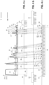
- the method for transmitting sensor data, in particular of an ultrasonic sensor, from a sensor to a computer system, in particular in a vehicle comprising the transmission of an ultrasonic burst with a start 57 and end 56 of the transmission of the ultrasonic burst and comprising the reception of an ultrasonic signal and forming a reception signal for a reception time T E at least from the end 56 of the transmission of the ultrasonic burst and comprising the transmission of the compressed data via a data bus, in particular a single-wire data bus, to the computer system
- the transmission 54 of the data from the sensor to the computer system begins with a start command 53 from the computer system to the sensor via the data bus and before the end 56 of the transmission of the ultrasonic burst or begins after a start command 53 from the computer system to the sensor via the data bus and before the start 57 of the transmission of the ultrasonic burst.
- the transmission 54 then takes place after the start command 53 periodically until the end of the data transmission 58
- a feature vector signal from the received signal as the first step of data compression.
- a feature vector signal can comprise several analog and digital data signals. It therefore represents a more or less complex data/signal structure. In the simplest case, it can be understood as a vector signal consisting of several partial signals.
- first and/or higher time derivative of the received signal or the simple or multiple integral of the received signal which are then partial signals within the feature vector signal.
- An envelope signal can also be formed, which is then a partial signal within the feature vector signal.
- the signal can be used as a transmitted ultrasonic signal that was used to control the driver for the transmitter or, on the other hand, for example, a signal that was measured at the transmitter and thus better corresponds to the sound wave actually emitted.
- a matched filter is a filter that determines the signal-to-noise ratio (signal to noise ratio (SNR). Predefined signal characteristics are to be recognized in the disturbed echo signal.
- SNR signal to noise ratio
- the terms “correlation filter”, “signal-adapted filter (SAF)” or just “adapted filter” are also often found.
- the optimal filter is used to optimally determine the presence (detection) of the amplitude and/or position of a known signal shape, the predetermined signal characteristic, even in the presence of interference (parameter estimation), for example from signals from other ultrasonic transmitters and/or ground echoes.
- the optimal filter signals are then preferably partial signals within the feature vector signal.
- Signal course characteristics therefore include not only special signal forms, such as rectangular pulses or wavelets or wave trains, but also distinctive points in the course of the received signal and/or in the course of signals derived from it, such as an envelope signal, which can be obtained from the received signal, for example, by filtering.
- Another signal which may be a sub-signal of the feature vector signal, may, for example, detect whether the envelope of the received signal, the envelope signal, crosses a predetermined first threshold value.
- Another signal which may be a sub-signal of the feature vector signal, may, for example, detect whether the envelope of the received signal, the envelope signal, crosses a predetermined second threshold value, which may be identical to the first threshold value, in an ascending manner.
- Another signal which may be a sub-signal of the feature vector signal, can, for example, detect whether the envelope of the received signal, the Envelope signal that crosses a predetermined third threshold, which may be identical to the first threshold, in a falling manner.
- Another signal which may be a sub-signal of the feature vector signal, may, for example, detect whether the envelope of the received signal, the envelope signal, has a maximum above a fourth threshold value, which may be identical to the aforementioned threshold values.
- Another signal which can be a partial signal of the feature vector signal, can detect, for example, whether the envelope of the received signal, the envelope signal, has a minimum above a fifth threshold value, which can be identical to the aforementioned threshold values. In this case, it is preferably evaluated whether the at least one preceding maximum of the envelope has a minimum distance from the minimum in order to avoid detection of noise. Other filtering is conceivable at this point. It can also be checked whether the time interval between this minimum and a preceding maximum is greater than a first minimum time interval. Fulfillment of these conditions sets a flag or signal, which itself is preferably a partial signal of the feature vector signal.
- the feature vector signal can be transformed into a significant feature vector signal in a significance enhancement stage. In practice, however, it has been shown that this is not yet necessary, at least not for today's requirements.
- the detection and classification of signal waveform characteristics into detected signal waveform characteristic classes within the received signal follows on the basis of the feature vector signal or the significant feature vector signal.
- the signal characteristic for which the optimal filter is designed can be considered to have been recognized.
- Other parameters are preferably also taken into account. For example, if an ultrasound burst was sent with increasing frequency during the burst (called chirp-up), an echo is also expected that has this modulation property. If the signal shape of the envelope, for example a triangular signal shape of the envelope, matches an expected signal shape locally in time, but not the modulation property, then this is not an echo from the transmitter, but an interference signal that may come from other ultrasound transmitters or from over-range.
- the system can then differentiate between self-echoes and external echoes, whereby one and the same signal form is assigned to two different signal characteristics, namely self-echoes and external echoes.
- the transmission of self-echoes is preferably prioritized over the transmission of external echoes, since the former are generally safety-relevant and the latter are generally not safety-relevant.
- At least one signal characteristic parameter is assigned to each detected signal characteristic or is determined for this signal characteristic.
- This is preferably a time stamp that indicates when the characteristic occurred in the echo signal.
- the time stamp can, for example, refer to the temporal start of the signal characteristic in the received signal or the temporal end or the temporal position of the temporal center of gravity of the signal characteristic, etc.
- Other signal characteristic parameters are also possible. such as amplitude, stretching, etc. are conceivable.
- at least one of the assigned signal characteristic parameters is transmitted with the at least one recognized class of signal characteristic, which is a time value and which indicates a temporal position that is suitable for inferring the time since the transmission of a previous ultrasonic burst.
- this is later used to determine a determined distance of an object (e.g. obstacle) from the surroundings of the vehicle depending on a time value determined and transmitted in this way.
- the prioritized transmission of the recognized signal characteristic classes follows, preferably together with the associated signal characteristic parameters.
- the transmission can also take place in more complex data structures. For example, it is conceivable to first transmit the times of the recognized safety-relevant signal characteristic (e.g. identified obstacles) and then the recognized signal characteristic classes of the safety-relevant signal objects. This further reduces the latency.
- the recognized safety-relevant signal characteristic e.g. identified obstacles
- the determination of a chirp value as an associated signal characteristic parameter which indicates whether the detected signal characteristic is an echo of an ultrasonic transmission burst with chirp-up or a chirp-down or a no-chirp characteristic is an echo of an ultrasonic transmission burst with chirp-up or a chirp-down or a no-chirp characteristic.
- “Chirp-up” means that the frequency within the received signal characteristic in the received signal increases.
- “Chirp-down” means that the frequency within the received signal characteristic in the received signal decreases.
- No-chirp means that the frequency within the received signal characteristic in the received signal remains essentially the same.
- a confidence signal (confidence value) can also be obtained by, for example, forming the correlation between the received signal or a signal derived from it on the one hand and a reference signal, for example the ultrasonic transmitted signal or another expected wavelet.
- the confidence signal is then typically a partial signal of the feature vector signal.
- a phase signal is also formed on this basis, which indicates the phase shift, for example, of the received signal or a signal formed therefrom (e.g. the confidence signal) compared to a reference signal, for example the ultrasonic transmission signal and/or another reference signal.
- a phase confidence signal can be formed by forming the correlation between the phase signal or a signal derived therefrom on the one hand and a reference signal and can be used as a partial signal of the feature vector signal.
- phase confidence signal When evaluating the feature vector signal, it is then useful to compare the phase confidence signal with one or more threshold values to generate a discretized phase confidence signal, which itself can become part of the feature vector signal.
- the evaluation of the feature vector signal and/or the significant feature vector signal can be carried out in such a way that one or more distance values are formed between the feature vector signal and one or more signal characteristic prototype values for recognizable signal characteristic classes.
- a distance value can be Boolean, binary, discrete, digital or analog.
- all distance values are linked to one another in a non-linear function. For example, if a triangular chirp-up echo is expected, a triangular chirp-down echo received can be rejected. This rejection is a non-linear process.
- At least one class of signal characteristic is a wavelet, which is estimated and thus detected by estimation devices (e.g. optimal filters) and/or estimation methods (e.g. estimation programs that run in a digital signal processor).
- estimation devices e.g. optimal filters
- estimation methods e.g. estimation programs that run in a digital signal processor
- wavelet refers to functions that can be used as the basis for a continuous or discrete wavelet transformation.
- the word is a neologism from the French "ondelette”, which means “small wave” and was translated into English partly literally ("onde” -> "wave") and partly phonetically ("-lette” -> "-let”).
- wavelets that have an integral that is different from 0 are also permissible. Examples of this are the rectangular and triangular wavelets described below.
- wavelets with 0-integral are the Haar wavelet (Alfréd Haar 1909), the Daubechies wavelets named after Ingrid Daubechies (around 1990), the Coiflet wavelets also constructed by her, and the more theoretically important Meyer wavelet (Yves Meyer, around 1988).
- Wavelets exist for spaces of any dimension, usually a tensor product of a one-dimensional wavelet basis is used. Due to the fractal nature of the two-scale equation in MRA, most wavelets have a complicated shape, most of them do not have a closed form. This is of particular importance because the previously mentioned feature vector signal is multidimensional and therefore allows the use of multidimensional wavelets for signal object detection.
- a special variant of the proposed method is therefore the use of multidimensional wavelets with more than two dimensions for signal object detection.
- a particularly suitable wavelet, in particular for analyzing the envelope signal is a triangular wavelet. This is characterized by a start time of the triangular wavelet, a temporally linear increase in the wavelet amplitude following the start time of the triangular wavelet up to a maximum of the amplitude of the triangular wavelet and a temporally linear decrease in the wavelet amplitude following the maximum of the triangular wavelet up to an end of the triangular wavelet.
- a rectangular wavelet is characterized by a starting time of the rectangular wavelet, which is followed by an increase in the wavelet amplitude of the rectangular wavelet with a first temporal steepness of the rectangular wavelet up to a first plateau time of the rectangular wavelet.
- the first plateau time of the rectangular wavelet is followed by a stagnation of the wavelet amplitude with a second steepness of the wavelet amplitude up to a second plateau time of the rectangular wavelet.
- the second plateau time of the rectangular wavelet is followed by a decrease with a third temporal steepness up to the temporal end of the rectangular wavelet.
- the amount of the second temporal steepness is less than 10% of the amount of the first temporal steepness and less than 10% of the amount of the third temporal steepness.
- the temporal shift of the relevant wavelet of the detected signal characteristic is used as a signal characteristic parameter, for example by correlation and/or the time at which the level of the output of an optimal filter suitable for detecting the relevant wavelet exceeds a predefined threshold value for this signal characteristic or this wavelet.
- the envelope of the received signal and/or a phase signal and/or a confidence signal etc. are evaluated.
- Another possible signal characteristic parameter that can be determined is a temporal compression or expansion of the relevant wavelet of the detected signal characteristic.
- An amplitude of the wavelet of the detected signal characteristic can also be determined.
- the various signal curve characteristics that are possible for a section of the received signal can be assigned scores that indicate the probability that this signal curve characteristic is present according to the estimation algorithm used. In the simplest case, such a score is binary. Preferably, however, it is a complex, real or integer number.
- the data of the recognized signal characteristic class and the associated data such as time stamps and score values of the respective recognized signal characteristic classes, i.e. the associated signal characteristic parameters, are transmitted according to the FIFO principle. This ensures that the data of the reflections of the closest objects are always transmitted first and the safety-critical case of a vehicle colliding with an obstacle is processed in a prioritized manner based on probability.
- the transmission of sensor error states can also take place. This can also take place during a reception time T E if the sensor determines through self-test devices that there is a defect and the previously transmitted data could potentially be faulty. This ensures that the computer system can become aware of a change in the evaluation of the measurement data at the earliest possible time and can reject it or treat it differently. This is of particular importance for emergency braking systems, since emergency braking is a safety-critical intervention that may only be initiated if the underlying data has a corresponding trust value.
- the transmission of the measurement data for example the date of the recognized signal characteristic class and/or the transmission of the assigned signal characteristic parameter, is therefore postponed and thus given a lower priority.
- the transmission will be aborted if an error occurs in the sensor. In some cases, however, an error may appear possible but not certain. is present. In such cases, the continuation of transmission is indicated.
- the transmission of safety-critical errors of the sensor is therefore preferably carried out with a higher priority.
- certain points in time in the course of the received signal can also be understood as signal course characteristics within the meaning of this invention, which can be used for data compression and can be transmitted instead of sample values of the received signal.
- signal course characteristics within the meaning of this invention, which can be used for data compression and can be transmitted instead of sample values of the received signal.
- the signal points in time are therefore a special form of signal course characteristics within the meaning of this invention.
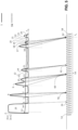
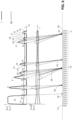
- a first possible signal time and thus a signal characteristic is a crossing of the amplitude of the envelope signal 1 with the amplitude of a threshold signal SW in an ascending direction.
- a second possible signal time and thus a signal characteristic is a crossing of the amplitude of the envelope signal 1 with the amplitude of a threshold signal SW in a descending direction.
- a third possible signal time and thus a signal characteristic is a maximum of the amplitude of the envelope signal 1 above the amplitude of a threshold signal SW.
- a fourth possible signal time point and thus a signal characteristic is a minimum of the amplitude of the envelope signal 1 above the amplitude of a threshold signal SW.
- the resulting grouping and temporal sequence of recognized signal characteristics can itself be recognized, for example by a Viterbi decoder, as a predefined, expected grouping or temporal sequence of signal characteristics and can thus itself represent a signal characteristic.
- a sixth possible signal time is and thus a signal characteristic such a predefined grouping and/or temporal sequence of other signal characteristics.
- the transmission of the recognized summary signal curve characteristic class and at least one associated signal curve characteristic parameter preferably follows instead of the transmission of the individual signal curve characteristics, since this saves considerable data bus capacity.
- the data of the signal curve characteristic class of a signal curve characteristic is transmitted, which is a predefined temporal sequence and/or grouping of other signal curve characteristics. In order to achieve compression, it is advantageous if at least one signal curve characteristic class of at least one of these other signal curve characteristics is not transmitted.
- a temporal grouping of signal curve characteristics is present in particular when the temporal distance between these signal curve characteristics does not exceed a predefined distance.
- the runtime of the signal in the optimal filter should be taken into account.
- the optimal filter is slower than the comparators. Therefore, the change in the output signal of the optimal filter should be in a fixed temporal relationship to the temporal occurrence of the relevant signal times.
- the data transmission in the vehicle takes place via a bidirectional single-wire data bus.
- the return line is preferably ensured by the body of the vehicle.
- the sensor data is sent to the computer system in a current-modulated manner.
- the data for controlling the sensor is sent to the sensor by the computer system, preferably in a voltage-modulated manner.
- the transmission of data from the sensor to the computer system should be modulated with a transmission current on the data bus, the current strength of which should be less than 50 mA, preferably less than 5 mA, preferably less than 2.5 mA.
- the current strength of which should be less than 50 mA, preferably less than 5 mA, preferably less than 2.5 mA.
- a computer system with a data interface to the data bus preferably the single-wire data bus, is required, which supports the decompression of the data compressed in this way.
- the computer system will not carry out complete decompression, but will only evaluate the time stamp and the detected signal characteristic type, for example.
- the sensor required to carry out one of the methods described above has at least one transmitter and at least one receiver for generating a received signal, which can also be combined as one or more transducers. Furthermore, it has at least devices for processing and compressing the received signal and a data interface for transmitting the data via the data bus, preferably the single-wire data bus, to the computer system.
- the compression device preferably has at least one of the following sub-devices: optimal filters, comparators, threshold signal generating devices for generating one or more threshold signals SW, comparators, differentiators for forming derivatives, integrators for forming integrated signals, other filters, envelope formers for generating an envelope signal from the received signal, correlation filters for comparing the received signal or signals derived therefrom with reference signals.
- the technical teachings from the prior art are all based on the idea of detecting an object in front of the vehicle using the ultrasonic sensor in the ultrasonic sensor and only then transmitting the object data after the objects have been detected.
- synergy effects are lost when using multiple ultrasonic transmitters, it was recognized within the scope of the invention that it does not make sense to transmit only the echo data from the ultrasonic sensor itself, but rather all the data.
- the data from several sensors can also be evaluated to advantage.
- the compression of the data for transmission over a data bus with a lower bus bandwidth must be carried out differently than in the state of the art. This can then lead to synergy effects.
- a vehicle has more than one ultrasonic sensor. In order to be able to distinguish between the two sensors, it is useful for these two sensors to transmit with different coding.
- both sensors should now record the ultrasonic echoes of both emissions from both ultrasonic sensors and transmit them in a suitably compressed manner to the central computer system, where the ultrasonic reception signals are reconstructed and fused.
- the obstacles objects in the environment
- This also enables the further fusion of the ultrasonic sensor data with the data of other sensor systems such as radar etc.
- the invention proposes a method for transmitting sensor data from a sensor to a computer system.
- the method is particularly suitable for transmitting data from an ultrasonic reception signal from an ultrasonic sensor to a control unit as a computer system in a vehicle.
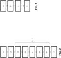
- the method is based on the Fig. 1
- an ultrasonic burst is first generated and emitted into a free space, typically in the vicinity of the vehicle (step ⁇ of the Fig. 1 ).
- An ultrasonic burst consists of several successive sound pulses with ultrasonic frequency. This ultrasonic burst is created by a mechanical oscillator in an ultrasonic transmitter or ultrasonic transducer slowly starting to oscillate and then oscillating again.
- the ultrasonic burst emitted by the exemplary ultrasonic transducer is then reflected by objects in the vicinity of the vehicle and received by an ultrasonic receiver or the ultrasonic transducer itself as an ultrasonic signal and converted into an electrical reception signal (step ⁇ of the Fig. 1 ).
- the ultrasonic transmitter is particularly preferably identical to the ultrasonic receiver, which is then referred to below as a transducer, which is an electroacoustic component that is operated alternately as an ultrasonic transmitter and ultrasonic receiver and thus as a sensor. The principle explained below can also be used for separate receivers and transmitters.
- the proposed ultrasonic sensor contains a signal processing unit that then analyses and compresses the electrical reception signal corresponding to the ultrasonic reception signal (hereinafter referred to as the "reception signal") (step ⁇ of the Fig. 1 ) in order to minimize the necessary data transmission (amount of data to be transmitted) and to create space for, for example, status messages and other control commands from the control computer to the signal processing unit or the ultrasonic sensor system.
- the compressed electrical reception signal is then transmitted to the computer system (step ⁇ of the
- the associated method is thus used to transmit sensor data, in particular of an ultrasonic sensor, from a sensor to a computer system, in particular in a vehicle. This is preceded by the transmission of an ultrasonic burst (step ⁇ of the Fig. 1 ) and receiving an ultrasonic signal and forming an electrical reception signal (step ⁇ of the Fig. 1 ). This is followed by data compression of the received signal (step ⁇ of the Fig. 1 ) to generate compressed data (step ⁇ of the
- Fig. 1 by detecting preferably at least two or three or more predetermined properties in the received signal.
- the electrical received signal is detected by sampling (step ⁇ a of Fig. 2 , in which the step ⁇ a is divided into five sub-steps, for example) into a sampled received signal, which consists of a time-discrete stream of samples.
- Each sample can typically be assigned a sampling time as a time stamp of this sample.
- the compression can be carried out, for example, by a wavelet transformation (step yb of the Fig. 2 ).
- the received ultrasound signal in the form of the sampled received signal can be compared with predetermined basic signal forms (referred to above as signal characteristics), which are stored in a library, for example, by forming a correlation integral (see also Wikipedia for this term) between the predetermined basic signal forms and the sampled received signal.
- the temporal sequence of basic signal forms in the received signal forms a signal object, which is assigned to one of several signal object classes.
- the correlation integral the associated spectral values of this signal object class are determined for each of these signal object classes. Since this happens continuously, the spectral values themselves represent a stream of time-discrete, instantaneous spectral values, whereby each spectral value can again be assigned a time stamp.
- An alternative, mathematically equivalent method is the use of optimal filters (English matched filters) for each predetermined signal object class (basic signal form). Since several signal object classes are usually used, which also have different can be subjected to temporal spreads (see also "Wavelet analysis"), this typically results in a time-discrete stream of multidimensional vectors of spectral values of different signal object classes and their different respective time spreads, with each of these multidimensional vectors being assigned a time stamp. Each of these multidimensional vectors is a so-called feature vector. It is therefore a time-discrete stream of feature vectors. Each of these feature vectors is preferably assigned a time stamp. (Step ⁇ b of the Fig. 2 ).
- the continuous temporal shift also results in a temporal dimension.
- the feature vector of the spectral values can also be supplemented with values from the past or values that depend on them, for example temporal integrals or derivatives or filter values of one or more of these values, etc. This can further increase the dimensionality of these feature vectors within the feature vector data stream.
- the isosceles triangle and the double-pointed triangle are particularly simple signal object classes.
- a signal object class usually consists of a given spectral coefficient vector, i.e. a given feature vector value.
- the amount of a distance between these properties, the elements of the vector of the instantaneous spectral coefficients (feature vector), and at least one combination of these properties (prototype) is determined in the form of a signal object class, which is represented by a given feature vector (prototype or prototype vector) from a library of given signal object class vectors (step ⁇ d of the Fig. 2
- the spectral coefficients of the feature vector are normalized before correlation with the prototypes (step yc of the Fig. 2 ).
- the distance determined in this distance determination can, for example, consist of the sum of all differences between one spectral coefficient of the given feature vector (prototype or prototype vector) of the respective prototype and the corresponding normalized spectral coefficient of the current feature vector of the ultrasound echo signal.
- a Euclidean distance would be formed by the root of the sum of the squares of all differences between one spectral coefficient of the given feature vector (prototype or prototype vector) of the prototype and the corresponding normalized spectral coefficient of the current feature vector of the ultrasound echo signal.
- this method of determining the distance is usually too complex. Other methods of determining the distance are conceivable.
- Each given feature vector (prototype or prototype vector) can then be assigned a symbol and, if necessary, a parameter, e.g.
- the distance value and/or the amplitude before normalization If the distance determined in this way falls below a first threshold value and is the smallest distance between the current feature vector value and one of the specified feature vector values (prototypes or values of the prototype vectors), its symbol is used as the recognized prototype. This creates a pair of recognized prototype and time stamp of the current feature vector.
- the data is then preferably transferred (step ⁇ of the Fig. 2 ), here the determined symbol that best symbolizes the recognized prototype, and for example the distance and the time of occurrence (time stamp) to the computer system only if the amount of this distance is below the first threshold and the recognized prototype is a prototype to be transmitted. It may be that prototypes that cannot be recognized are also stored, for example for noise, e.g.
- a prototype is therefore recognized if the amount of the determined distance between the current feature vector value and the given feature vector value (prototype or value of the prototype vector) is below this first threshold (step ⁇ e of the Fig. 2 ).
- the ultrasonic echo signal itself is no longer transmitted, but only a sequence of symbols for recognized typical temporal signal curves within the echo signal and time stamps associated with these signal curves in a certain time period (step ⁇ of the Fig. 2 ).
- the recognized signal form prototype Preferably, only one symbol for the recognized signal form prototype, its parameters (e.g. envelope amplitude and/or time extension) and a temporal reference point of the occurrence of this signal form prototype (the time stamp) as a recognized signal object are transmitted for each recognized signal object.
- the transmission of the individual sample values or of times at which threshold values are exceeded by the envelope of the sampled received signal, etc. is omitted. In this way, this selection of the relevant prototypes leads to massive data compression and a reduction in the required bus bandwidth.
- an estimated value - here, for example, the inverse distance between the representative of the signal object class in the form of the specified feature vector (prototype or prototype vector) - and the compressed data is then transmitted to the computer system if the amount of this estimated value (e.g. inverse distance) is above a second threshold value or the inverse estimated value is below a first threshold value.
- the signal processing unit of the ultrasonic sensor thus carries out data compression of the received signal to generate compressed data.
- the ultrasonic sensor then transmits the data compressed in this way, preferably only the coding (symbols) of the prototypes thus recognized, their amplitude and/or temporal extension and the time of occurrence (time stamp) to the computer system.
- data should be transmitted via the data bus in a prioritized manner.
- Messages of safety-critical errors from the sensor, in this case the ultrasonic sensor, for example, to the computer system have the highest priority, as these are highly likely to affect the validity of the measurement data from the ultrasonic sensor.
- This data is sent from the sensor to the computer system.
- the second highest priority is requests from the computer system to carry out safety-relevant self-tests. Such commands are sent from the computer system to the sensor.
- the third highest priority is the data from the ultrasonic sensor itself, as the latency time must not be increased. All other data has an (even) lower priority with regard to its transmission via the data bus.
- a further variant of the proposed method thus provides for the formation of a feature vector signal (stream of feature vectors with n feature vector values and n as the dimension of the feature vector) from the received signal as the first step of data compression.
- a feature vector signal can comprise several analog and digital data signals.
- the feature vector signal therefore represents a temporal sequence of more or less complex data/signal structures. In the simplest case, it can be understood as a vector signal consisting of several partial signals.
- first and/or higher time derivative of the received signal or the simple or multiple integral of the received signal, which are sub-signals within the feature vector signal may be useful to form a first and/or higher time derivative of the received signal or the simple or multiple integral of the received signal, which are sub-signals within the feature vector signal.
- An envelope signal of the received signal can also be formed, which is then a partial signal within the feature vector signal.
- the signal can be used as a transmitted ultrasonic signal that was used to control the driver for the transmitter, or on the other hand, for example, a signal can be used that was measured at the transmitter and thus better corresponds to the sound wave actually emitted.
- a matched filter is a filter that optimizes the signal-to-noise ratio (SNR).
- SNR signal-to-noise ratio
- the predefined signal objects are to be recognized in the disturbed ultrasonic reception signal.
- correlation filter signal-matched filter (SAF) or just matched filter are also often found.
- the optimal filter is used to optimally determine the presence (detection) of a known signal form, the predetermined signal object, in the presence of interference (parameter estimation). This interference can be, for example, signals from other ultrasonic transmitters and/or ground echoes.
- the optimal filter output signals are then preferably partial signals within the feature vector signal.
- Basic signal objects therefore do not include signal shapes such as rectangular pulses or other forms of wavelets or wave trains, but rather distinctive points in the course of the received signal and/or in the course of signals derived from it, such as a derived envelope signal, which can be obtained from the received signal, for example, by filtering.
- Another signal which can be a sub-signal of the feature vector signal, can detect, for example, whether the envelope of the received signal, the envelope signal, crosses a predetermined third threshold value. It is therefore a signal that signals the presence of a basic signal object within the received signal and thus the feature vector signal.
- Another signal which may be a sub-signal of the feature vector signal, may, for example, detect whether the envelope of the received signal, the envelope signal, exceeds a predetermined fourth threshold value, which is connected to the third Threshold value can be identical and crosses ascending. It is therefore a signal that signals the presence of a basic signal object within the received signal and thus the feature vector signal.
- Another signal which can be a sub-signal of the feature vector signal, can detect, for example, whether the envelope of the received signal, the envelope signal, crosses a predetermined fifth threshold value, which can be identical to the third or fourth threshold value, in a falling manner. It is therefore a signal that signals the presence of a basic signal object within the received signal and thus the feature vector signal.
- Another signal which can be a partial signal of the feature vector signal, can detect, for example, whether the envelope of the received signal, the envelope signal, has a maximum above a sixth threshold value, which can be identical to the aforementioned third to fifth threshold values. It is therefore a signal that signals the presence of a basic signal object within the received signal and thus the feature vector signal.
- Another signal which can be a partial signal of the feature vector signal, can detect, for example, whether the envelope of the received signal, the envelope signal, has a minimum above a seventh threshold value, which can be identical to the aforementioned third to sixth threshold values. It is therefore a signal that signals the presence of a basic signal object within the received signal and thus the feature vector signal.
- the at least one preceding maximum of the envelope curve has a minimum distance to the minimum in order to avoid detection of noise.
- Other filtering in this regard is conceivable.
- the feature vector signal can be transformed into a significant feature vector signal in a significance enhancement stage, e.g. by a linear mapping or by a higher-order matrix polynomial. In practice, however, it has been shown that this is not yet necessary, at least for today's requirements.
- the detection and classification of signal objects into detected signal object classes within the received signal follows based on the feature vector signal or the significant feature vector signal.
- the signal object that the optimal filter is designed to detect can be considered to have been detected.
- Other parameters are preferably also taken into account. For example, if an ultrasound burst was sent with increasing frequency during the burst (so-called chirp-up), an echo is also expected that has this modulation property. If the signal shape of the envelope, for example a triangular signal shape of the envelope, matches an expected signal shape locally in time, but not with the modulation property, This means that it is not an echo from the transmitter, but an interference signal that may come from other ultrasonic transmitters or from excessive range.
- the system can then differentiate between self-echoes and external echoes, whereby one and the same signal form is assigned to two different signal objects, namely self-echoes and external echoes.
- the transmission of self-echoes via the data bus from the sensor to the computer system is preferably prioritized over the transmission of external echoes, since the former are generally safety-relevant and the latter types of echo are generally not safety-relevant.
- At least one signal object parameter is assigned to each detected signal object or is determined for this signal object.
- This is preferably a time stamp that indicates when the object was received.
- the time stamp can refer, for example, to the temporal start of the signal object in the received signal or the temporal end or the temporal length of the signal object or the temporal position of the temporal center of gravity of the signal object, etc.
- Other signal object parameters such as amplitude, stretching, etc. are also conceivable.
- at least one of the assigned signal object parameters is thus transmitted with a symbol for the at least one signal object class to which the at least one detected signal object belongs.
- the signal object parameter is preferably a time value as a time stamp and indicates a temporal position that is suitable for inferring the time since the transmission of a previous ultrasound burst. Preferably, this is later used to determine the distance of an object depending on a time value determined and transmitted in this way.
- the prioritized transmission of the recognized signal object classes follows in the form of assigned symbols with time stamps, preferably together with the assigned signal object parameters.
- the transmission can also take place in more complex data structures (English: records). For example, It is conceivable to first transmit the times of the detected safety-relevant signal objects (e.g. for identified obstacles) and then the detected signal object classes of the safety-relevant signal objects. This further reduces the latency.
- the proposed method comprises, at least in one variant, determining a chirp value as an associated signal object parameter, which indicates whether the detected signal object is an echo of an ultrasonic transmission burst with chirp-up or with chirp-down or with no-chirp properties.
- Chirp-up means that the frequency within the received signal object increases in the received signal.
- Chirp-down means that the frequency within the received signal object decreases in the received signal.
- No-chirp means that the frequency within the received signal object remains essentially the same in the received signal.
- phase confidence signal When evaluating the feature vector signal, it may be useful to compare the phase confidence signal with one or more threshold values to generate a discretized phase confidence signal, which itself can become a sub-signal of the feature vector signal.
- the evaluation of the feature vector signal and/or the significant feature vector signal can be carried out in such a way that one or more distance values are formed between the feature vector signal and one or more signal object prototype values for recognizable signal object classes.
- a distance value can be Boolean, binary, discrete, digital or analog.
- all distance values are linked to one another in a non-linear function. For example, if a triangular chirp-up echo is expected, a triangular chirp-down echo received can be rejected. This rejection is a "non-linear" process in the sense of the invention.
- the various signal objects that are possible for a section of the received signal can be assigned scores that indicate the probability that the presence of this signal object is assigned according to the estimation algorithm used. In the simplest case, such a score is binary. Preferably, however, it is a complex, real or integer number. It can be the determined distance, for example.
- the transmission of sensor error states can also take place. This can also take place during a reception time (T E ) if the sensor determines through self-test devices that there is a defect and that the previously transmitted data could be incorrect. This ensures that the computer system can become aware of a change in the evaluation of the measurement data at the earliest possible time and can reject it or treat it differently. This is of particular importance for emergency braking systems, since emergency braking is a safety-critical intervention that may only be initiated if the underlying data has a corresponding trust value, and for other driver assistance systems.
- the transmission of the measurement data for example the date of the recognized signal object class and/or the transmission of the one assigned signal object parameter, is therefore postponed and thus given a lower priority. It is also conceivable that the transmission will be aborted if an error occurs in the sensor. However, an error may also appear possible, but not certainly exist. In such cases, it may therefore be advisable to continue the transmission in certain circumstances.
- the transmission of safety-critical errors of the sensor is therefore preferably given a higher priority.
- a first possible signal progression point and thus a basic signal object is a crossing of the progression of the envelope signal (1) with a threshold signal (SW) in ascending direction.
- a second possible signal progression point and thus a basic signal object is a crossing of the progression of the envelope signal (1) with a threshold signal (SW) in a descending direction.
- SW threshold signal
- a third possible signal curve point and thus a basic signal object is a local or absolute maximum in the course of the envelope signal (1) above the amplitude of a thirteenth threshold signal (SW).
- a fourth possible signal curve point and thus a basic signal object is a local or absolute minimum in the course of the envelope signal (1) above a threshold signal (SW).
- SW threshold signals
- the exemplary signal object of a triangular wavelet in this example therefore consists of the predefined sequence of three basic signal objects, by means of which a signal object is recognized and assigned to a signal object class, whereby this information is transmitted as a symbol of the signal object class and by parameters describing the recognized signal object, such as in particular the time of occurrence, i.e. the time stamp.
- this exceeding of the said minimum level at the output of the said optimal filter is another example of a fifth possible signal time and thus another possible basic signal object.
- the resulting grouping and temporal sequence of recognized basic signal objects can itself be recognized, for example by a Viterbi decoder, as a predefined, expected grouping or temporal sequence of basic signal objects and can thus itself represent a basic signal object.
- a sixth possible signal progression point and thus a basic signal object is the occurrence of such a predefined grouping and/or temporal sequence of other basic signal objects. If such a grouping of basic signal objects or a temporal sequence of such signal object classes is recognized in the form of a signal object, the symbol of this recognized summary signal object class and at least one associated signal object parameter are preferably transmitted instead of the individual signal basic objects, as this saves considerable data bus capacity. However, there may also be cases in which both are transmitted.
- the data (symbol) of the signal object class of a signal object is transmitted, which is a predefined temporal sequence and/or grouping of other signal basic objects.
- the data (symbol) of the signal object class of a signal object is transmitted, which is a predefined temporal sequence and/or grouping of other signal basic objects.
- a temporal grouping of basic signal objects is particularly present when the temporal distance between these basic signal objects does not exceed a predefined distance.
- the runtime of the signal in the optimal filter should be taken into account.
- the optimal filter should be slower than the comparators. Therefore, the change in the output signal of the optimal filter should be in a fixed temporal relationship to the temporal occurrence of the relevant signal times.
- a method for transmitting sensor data, in particular of an ultrasonic sensor, from a sensor to a computer system, in particular in a vehicle begins after the transmission of an ultrasonic burst and the reception of an ultrasonic signal and the formation of a time-discrete received signal consisting of a sequence of sample values.
- Each sample value is assigned a time date (time stamp).
- the method begins with the determination of at least two parameter signals, each relating to the presence of a signal base object assigned to the respective parameter signal, with the aid of at least one suitable filter (e.g. an optimal filter) from the sequence of sample values of the received signal.
- the resulting Parameter signals are also designed as a time-discrete sequence of respective parameter signal values (feature vector values), each of which is correlated with a date (time stamp).
- each parameter signal value feature vector value
- time stamp time stamp
- These parameter signals together are referred to below as a feature vector signal.
- the feature vector signal is thus designed as a time-discrete sequence of feature vector signal values, each with n parameter signal values, which consist of the parameter signal values and further parameter signal values, each with the same time date (time stamp).
- n is the dimensionality of the individual feature vector signal values, which are preferably the same from one feature vector value to the next feature vector value.
- Each feature vector signal value formed in this way is assigned this respective time date (time stamp).
- a signal object consists of a temporal sequence of basic signal objects. A symbol is typically assigned to the signal object in a predefined manner. Figuratively speaking, this checks whether the point to which the n-dimensional feature vector signal points in the n-dimensional phase space approaches predetermined points in this n-dimensional phase space at a distance closer than a predetermined maximum distance as it moves through the n-dimensional phase space in a predetermined temporal sequence.
- An evaluation value e.g.
- a distance is then calculated, which can, for example, reflect the probability of a certain sequence being present.
- This evaluation value which is again assigned a time date (time stamp)
- time stamp is then compared with a threshold vector to form a Boolean result that can have a first and a second value. If this Boolean result has the first value for this time date (time stamp), the symbol of the signal object and the value assigned to this symbol are transmitted. time date (time stamp) from the sensor to the computer system. If necessary, further parameters can be transmitted depending on the detected signal object.
- the data transmission in the vehicle is particularly preferably carried out via a serial bidirectional single-wire data bus.
- the electrical return line is preferably ensured by the body of the vehicle.
- the sensor data is preferably sent to the computer system in a current-modulated manner.
- the data for controlling the sensor is preferably sent to the sensor by the computer system in a voltage-modulated manner.
- the use of a PSI5 data bus and/or a DSI3 data bus is particularly suitable for data transmission. It was also recognized that it is particularly advantageous to transmit the data to the computer system at a transmission rate of > 200 kbit/s and from the computer system to the at least one sensor at a transmission rate of > 10 kbit/s, preferably 20 kbit/s.
- the transmission of data from the sensor to the computer system should be modulated with a transmission current on the data bus, the current strength of which should be less than 50 mA, preferably less than 5 mA, preferably less than 2.5 mA.
- the current strength of which should be less than 50 mA, preferably less than 5 mA, preferably less than 2.5 mA.
- the proposed method for transmitting sensor data, in particular of an ultrasonic sensor, from a sensor to a computer system, in particular in a vehicle is carried out as follows: This is preceded, for example, by the transmission of an ultrasonic burst and the reception of an ultrasonic signal, typically a reflection, and the formation of a time-discrete received signal consisting of a temporal sequence of sample values. Each sample value is assigned a time date (time stamp). This typically reflects the time of the sampling.
- a first parameter signal of a first property is determined according to the invention using a first filter from the sequence of sample values of the received signal.
- the parameter signal is again formed as a time-discrete sequence of parameter signal values.
- Each parameter signal value is again assigned exactly one time date (time stamp).
- this date corresponds to the most recent time date of a sample value that was used to form this respective parameter signal value.
- at least one further parameter signal and/or a property associated with this further parameter signal is determined using a further filter associated with this further parameter signal from the sequence of sample values of the received signal, wherein the further parameter signals are again each designed as time-discrete sequences of further parameter signal values.
- each further parameter signal value is assigned the same time date (time stamp) as the corresponding parameter signal value.
- the first parameter signal and the other parameter signals are referred to together below as the parameter vector signal or feature vector signal.
- This feature vector signal thus represents a time-discrete sequence of feature vector signal values, which consist of the parameter signal values and other parameter signal values, each with the same time date (time stamp). This means that each feature vector signal value formed in this way, i.e. each parameter signal value, can be assigned this respective time date (time stamp).
- the comparison of the feature vector signal values of a temporal date (time stamp) with a threshold vector is then preferably carried out quasi-continuously, forming a Boolean result that can have a first and a second value.
- a threshold vector which is preferably a prototype vector
- the Boolean result has a first value
- a further threshold value that represents a further component of the threshold vector
- the last step in this case is to transfer the symbol and, if applicable, also the feature vector signal values and the time date (time stamp) assigned to this symbol or feature vector signal value from the sensor to the computer system if the Boolean result for this time date (time stamp) has the first value.
- a sensor system is proposed with at least one computer system that is capable of carrying out one of the previously presented methods, and with at least two sensors that are also capable of carrying out one of the previously presented methods, so that these at least two sensors can communicate with the computer system by signal object recognition and are also able to transmit external echoes in a compacted manner and to make this information available to the computer system.
- the sensor system is therefore typically designed so that the data transmission between the at least two sensors and the computer system takes place or can take place in accordance with the previously described methods.
- one ultrasonic reception signal i.e. at least two ultrasonic reception signals, is typically compressed using one of the previously proposed methods and sent to the computer system.
- the at least two ultrasonic reception signals are reconstructed within the computer system to form reconstructed ultrasonic reception signals.
- the computer system uses reconstructed ultrasonic reception signals to detect objects in the vicinity of the sensors.
- the sensors do not perform this object detection. They only provide the data relating to the coding of detected signal objects and their parameters and thus transmit the received signal curve in a compressed form.
- the computer system preferably also detects objects, i.e. obstacles in the vicinity of the sensors, with the help of the reconstructed ultrasonic reception signals and, if necessary, additional signals from other sensors, in particular the signals from radar sensors.
- the computer system preferably creates an environment map for the sensors or a device to which the sensors belong or which has the sensors as a component based on the detected objects.
- the compressed transmission of signal progression data between the sensor and the computer system via the data bus proposed according to the invention reduces the data bus load and thus the criticality with regard to EMC requirements and also creates free data bus capacities for the transmission of control commands from the computer system to the sensor and for the transmission of status information and other data from the sensor to the computer system.
- the proposed prioritization with which the compressed data of the received signal progression and other data such as status information or error messages are transmitted ensures that safety-relevant data is transmitted first and thus no unnecessary dead times occur in the sensor.
- Fig. 3a shows the temporal course of a conventional ultrasonic echo signal (1) (see the wider solid line) and its conventional evaluation in freely selected units.
- a threshold signal (SW) (see the dashed line) is carried along.
- the output (2) (see the thinner solid line) is set to logic 1.
- This is a temporal analog interface with a digital output level. Further evaluation is then carried out in the sensor's control unit. Signaling errors or controlling the sensor is not possible via this state-of-the-art analog interface.
- Fig. 3b shows the time course of a conventional ultrasonic echo signal (1) and its conventional evaluation in freely selected units.
- a threshold signal (SW) is carried along.
- the output (2) is now set to a level corresponding to the size of the detected reflection (see the wider dot-dash line). It is a temporally analog interface with an analog output level. Further evaluation is then carried out in the sensor. Signaling of errors or controlling the sensor is not possible via this state-of-the-art analog interface.
- Fig. 3d The principle of symbolic signal transmission is explained. Instead of the signal from Figure 3c As an example, only two types of (triangular) signal objects are transmitted here. Specifically, these are a first triangular object (A) (in Fig. 3d shown for both the chirp-up and chirp-down cases) and a second triangular object (B) (shown for the chirp-down case). At the same time, the time and the peak values as well as, if applicable, the base width of the triangle object. If the signal is reconstructed on the basis of this data, a signal corresponding to Figure 3d . The signal components that did not correspond to the triangle signals were removed from this signal. This means that unrecognized signal components were discarded, which leads to massive data compression.
- A first triangular object
- B second triangular object
- Fig. 4a shows the unclaimed conventional analog transmission of the intersection points of the envelope signal (1) of the ultrasonic echo signal with the threshold signal (SW).
- Fig. 4b shows the unclaimed transmission of analyzed data after complete reception of the ultrasonic echo.
- Fig. 4c shows the claimed transmission of compressed data, whereby in this example symbols for basic signal objects are transmitted largely without compression.
- Fig. 5 shows the claimed transmission of compressed data, whereby in this example symbols for basic signal objects are compressed to symbols for signal objects.
- a first triangular object (59) is compressed, which is characterized by the temporal sequence of the threshold value being exceeded, the maximum and the threshold value being undershot (see the temporal sequence of the signal curve points 5, 6, 7 in the time course of the ultrasonic echo signal in the upper diagram of the Fig. 5 ), is detected and transmitted.
- a double peak with a saddle point (60) above the threshold signal is then detected.
- the characteristic feature here is the sequence of the envelope signal (1) exceeding the threshold signal (SW), the maximum of the envelope signal (1), the minimum above the threshold signal (SW), the maximum above the threshold signal (SW) and the undershoot of the threshold signal (SW) (see signal curve points 8, 9, 10, 11, 12 in the upper diagram).
- the symbol for this double peak with saddle point is transmitted.
- a time stamp is also transmitted.
- other parameters of the double peak with saddle point are also transmitted, such as the Positions of the maxima and the minimum or a scaling factor.
- a triangle signal i.e. a basic signal object
- the maximum of the envelope signal again followed by the envelope signal falling below the threshold signal (SW) (see signal curve points 13, 14, 15 in the upper diagram).
- the detection of a double peak (62) again, but now the minimum of the envelope signal is below the threshold signal (SW) (see signal curve points 16, 17, 18, 19, 20, 21 in the upper diagram).
- This double peak can therefore be treated as a separate signal object, for example.
- the triangle signal from signal curve points 22, 23, 24 in the above diagram is detected. As can easily be seen, this treatment of the signal leads to a massive data reduction.
- Fig. 6 shows the claimed transmission of compressed data according to Fig. 3 , whereby in this example not only the envelope signal but also a confidence signal is evaluated.
- Threshold signals are indicated with thick dashed lines.
- the received signal is only evaluated when it exceeds the threshold signal.
- the dotted signal line in the middle diagram of the Fig. 6 indicates that a signal object is modulated with chirp-up or modulated with chirp-down (see also the Figs. 3c and 3d , in which the different diagonal hatchings distinguish between chirp-up and chirp-down).
- a dotted signal line running upwards means that the signal object has been recognized as chirp-up modulated, while a dotted signal line running downwards means that the signal object has been recognized as chirp-down modulated.
- a signal object consists of one or more basic signal objects, i.e. a signal curve object consists of one or more signal curve characteristics.
- a signal object belongs to one of several signal object classes.
- a signal object can be described by one or more signal object parameters, for example with regard to position, size, distortion and stretching.
- a basic signal object can also be referred to as a basic signal characteristic, i.e. a signal characteristic.
- Parameters additionally describe the shape of the signal object.
- a feature vector signal consists of several parameter signals.
- a value of the feature vector signal consists of several parameter signal values.
- a feature vector signal value also called a parameter vector signal value, comprises multiple parameter signal values.
Landscapes
- Engineering & Computer Science (AREA)
- Radar, Positioning & Navigation (AREA)
- Remote Sensing (AREA)
- Physics & Mathematics (AREA)
- Computer Networks & Wireless Communication (AREA)
- General Physics & Mathematics (AREA)
- Acoustics & Sound (AREA)
- Measurement Of Velocity Or Position Using Acoustic Or Ultrasonic Waves (AREA)
- Traffic Control Systems (AREA)
Applications Claiming Priority (4)
| Application Number | Priority Date | Filing Date | Title |
|---|---|---|---|
| EP17171320 | 2017-05-16 | ||
| DE102018106241 | 2018-03-16 | ||
| EP18723848.0A EP3625588B1 (fr) | 2017-05-16 | 2018-05-16 | Procédé de transmission de données via un bus de données de véhicule provenant d'un système à ultra-sons à un dispositif informatique |
| PCT/EP2018/062808 WO2018210966A1 (fr) | 2017-05-16 | 2018-05-16 | Procédé de transmission de données via un bus de données de véhicule d'un système à ultrasons à un dispositif de traitement de données |
Related Parent Applications (1)
| Application Number | Title | Priority Date | Filing Date |
|---|---|---|---|
| EP18723848.0A Division EP3625588B1 (fr) | 2017-05-16 | 2018-05-16 | Procédé de transmission de données via un bus de données de véhicule provenant d'un système à ultra-sons à un dispositif informatique |
Publications (2)
| Publication Number | Publication Date |
|---|---|
| EP4465084A2 true EP4465084A2 (fr) | 2024-11-20 |
| EP4465084A3 EP4465084A3 (fr) | 2025-02-26 |
Family
ID=62148395
Family Applications (4)
| Application Number | Title | Priority Date | Filing Date |
|---|---|---|---|
| EP24205011.0A Pending EP4465084A3 (fr) | 2017-05-16 | 2018-05-16 | Procédé de transmission de données sur un bus de données de véhicule d'un système à ultrasons vers un dispositif de traitement de données |
| EP24205018.5A Pending EP4465085A3 (fr) | 2017-05-16 | 2018-05-16 | Procédé de transmission de données sur un bus de données de véhicule d'un système à ultrasons vers un dispositif de traitement de données |
| EP24204995.5A Pending EP4465083A3 (fr) | 2017-05-16 | 2018-05-16 | Procédé de transmission de données sur un bus de données de véhicule d'un système à ultrasons vers un dispositif de traitement de données |
| EP18723848.0A Active EP3625588B1 (fr) | 2017-05-16 | 2018-05-16 | Procédé de transmission de données via un bus de données de véhicule provenant d'un système à ultra-sons à un dispositif informatique |
Family Applications After (3)
| Application Number | Title | Priority Date | Filing Date |
|---|---|---|---|
| EP24205018.5A Pending EP4465085A3 (fr) | 2017-05-16 | 2018-05-16 | Procédé de transmission de données sur un bus de données de véhicule d'un système à ultrasons vers un dispositif de traitement de données |
| EP24204995.5A Pending EP4465083A3 (fr) | 2017-05-16 | 2018-05-16 | Procédé de transmission de données sur un bus de données de véhicule d'un système à ultrasons vers un dispositif de traitement de données |
| EP18723848.0A Active EP3625588B1 (fr) | 2017-05-16 | 2018-05-16 | Procédé de transmission de données via un bus de données de véhicule provenant d'un système à ultra-sons à un dispositif informatique |
Country Status (6)
| Country | Link |
|---|---|
| US (6) | US11719785B2 (fr) |
| EP (4) | EP4465084A3 (fr) |
| JP (3) | JP7165145B2 (fr) |
| CN (4) | CN118033611A (fr) |
| DE (11) | DE112018000300A5 (fr) |
| WO (1) | WO2018210966A1 (fr) |
Families Citing this family (51)
| Publication number | Priority date | Publication date | Assignee | Title |
|---|---|---|---|---|
| DE102018010257A1 (de) * | 2018-03-16 | 2019-09-19 | Elmos Semiconductor Aktiengesellschaft | Klassifikation von Signalobjekten innerhalb von Ultraschallempfangssignalen und komprimierten Übertragung von Symbolen als Repräsentanten dieser Signalobjekte an eine Rechnereinheit zur Objekterkennung |
| DE102019009247B4 (de) | 2018-03-16 | 2025-03-13 | Elmos Semiconductor Se | Ultraschallsensorsystem mit zwei Ultraschallsensoren, die Ultraschall-Echo-Signal-Modelle verwenden |
| DE102018010255A1 (de) * | 2018-03-16 | 2019-09-19 | Elmos Semiconductor Aktiengesellschaft | Klassifikation von Signalobjekten innerhalb von Ultraschallempfangssignalen und komprimierten Übertragung von Symbolen als Repräsentanten dieser Signalobjekte an eine Rechnereinheit zur Objekterkennung |
| DE102018010258A1 (de) * | 2018-03-16 | 2019-09-19 | Elmos Semiconductor Aktiengesellschaft | Klassifikation von Signalobjekten innerhalb von Ultraschallempfangssignalen und komprimierten Übertragung von Symbolen als Repräsentanten dieser Signalobjekte an eine Rechnereinheit zur Objekterkennung |
| DE102018010260A1 (de) * | 2018-03-16 | 2019-09-19 | Elmos Semiconductor Aktiengesellschaft | Klassifikation von Signalobjekten innerhalb von Ultraschallempfangssignalen und komprimierten Übertragung von Symbolen als Repräsentanten dieser Signalobjekte an eine Rechnereinheit zur Objekterkennung |
| DE102019105651B4 (de) | 2018-03-16 | 2023-03-23 | Elmos Semiconductor Se | Klassifikation von Signalobjekten innerhalb von Ultraschallempfangssignalen und komprimierte Übertragung von Symbolen als Repräsentanten dieser Signalobjekte an eine Rechnereinheit zur Objekterkennung |
| DE102018010261A1 (de) * | 2018-03-16 | 2019-09-19 | Elmos Semiconductor Aktiengesellschaft | Klassifikation von Signalobjekten innerhalb von Ultraschallempfangssignalen und komprimierten Übertragung von Symbolen als Repräsentanten dieser Signalobjekte an eine Rechnereinheit zur Objekterkennung |
| DE102018010254A1 (de) * | 2018-03-16 | 2019-09-19 | Elmos Semiconductor Aktiengesellschaft | Klassifikation von Signalobjekten innerhalb von Ultraschallempfangssignalen und komprimierten Übertragung von Symbolen als Repräsentanten dieser Signalobjekte an eine Rechnereinheit zur Objekterkennung |
| DE102018106247A1 (de) * | 2018-03-16 | 2019-09-19 | Elmos Semiconductor Aktiengesellschaft | Klassifikation von Signalobjekten innerhalb von Ultraschallempfangssignalen und komprimierten Übertragung von Symbolen als Repräsentanten dieser Signalobjekte an eine Rechnereinheit zur Objekterkennung |
| US11733377B2 (en) | 2018-05-07 | 2023-08-22 | Texas Instruments Incorporated | Time of flight and code signature detection for coded ultrasonic transmission |
| US11644555B2 (en) | 2018-07-27 | 2023-05-09 | Texas Instruments Incorporated | Threshold generation for coded ultrasonic sensing |
| US11378686B2 (en) | 2018-12-26 | 2022-07-05 | Texas Instruments Incorporated | Ultrasonic echo processing in presence of Doppler shift |
| US12372643B2 (en) * | 2019-01-11 | 2025-07-29 | Texas Instruments Incorporated | Coded ultrasonic sensing with staggered bursts |
| DE102019106204B4 (de) | 2019-03-12 | 2023-04-27 | Elmos Semiconductor Se | Ultraschallsystem mit zentralisierter Objekterkennung auf Basis von dekomprimierten Ultraschallsignalen mehrerer Sensoren und zugehöriges Kompressionsverfahren |
| DE102019009129A1 (de) * | 2019-03-12 | 2020-09-17 | Elmos Semiconductor Se | Beendigungsverfahren für ein approximierendes Kompressionsverfahren für Ultraschallsensordaten |
| DE102019009130A1 (de) * | 2019-03-12 | 2020-09-17 | Elmos Semiconductor Se | Approximierendes Kompressionsverfahren für Ultraschallsensordaten |
| DE102019215393A1 (de) * | 2019-10-08 | 2021-04-08 | Robert Bosch Gmbh | Verfahren und eine Vorrichtung zur Klassifizierung eines Objektes, insbesondere im Umfeld eines Kraftfahrzeugs |
| KR102355438B1 (ko) * | 2019-11-28 | 2022-01-26 | 주식회사 씨자인 | 초음파 센서를 이용한 사물 인식 시스템 및 그 인식 방법 |
| US20210241546A1 (en) * | 2020-02-04 | 2021-08-05 | XL Hybrids | Data extraction apparatuses, systems, and methods |
| CN111815201B (zh) * | 2020-07-31 | 2022-11-29 | 中国汽车工程研究院股份有限公司 | 一种新能源汽车连续抽样体系的建立及泛特征测定方法 |
| US20220148411A1 (en) * | 2020-11-06 | 2022-05-12 | Ford Global Technologies, Llc | Collective anomaly detection systems and methods |
| CN112347958B (zh) * | 2020-11-13 | 2023-11-10 | 深圳市海洋王电网照明技术有限公司 | 障碍物检测信号的识别方法、识别电路及手势识别设备 |
| US20220230655A1 (en) * | 2021-01-15 | 2022-07-21 | Continental Automotive Systems Inc. | Method and device for detecting characteristic frequencies with a sensor |
| CN112890859B (zh) * | 2021-01-19 | 2024-01-09 | 广州多浦乐电子科技股份有限公司 | 基于超声波信号特征向量的数据处理方法及系统 |
| JP7472820B2 (ja) * | 2021-02-16 | 2024-04-23 | 株式会社Soken | 物体検知装置 |
| LU500348B1 (de) * | 2021-06-29 | 2022-12-29 | Toposens Gmbh | Verfahren beim Ermitteln eines Sendesignals in wenigstens einem empfangenen Signal |
| CN113556795B (zh) * | 2021-07-20 | 2023-03-24 | 哈尔滨海能达科技有限公司 | 首次转发设备的确定方法、相关装置及计算机存储介质 |
| CN113777614B (zh) * | 2021-09-07 | 2024-07-05 | 珠海上富电技股份有限公司 | 一种超声波雷达数据传输方法及其系统 |
| DE102022005056B3 (de) | 2022-08-10 | 2024-02-08 | Elmos Semiconductor Se | Modifizierte UART Datenübertragung für die zeitnahe Datenübertragung von Echodaten an ein übergeordnetes Rechnersystem mit Fehlererkennung |
| DE102022005040B3 (de) | 2022-08-10 | 2024-02-08 | Elmos Semiconductor Se | Modifizierte UART Schnittstelle für die zeitnahe Datenübertragung von Echodaten an ein übergeordnetes Rechnersystem und Kommandoempfang in einer Kommandophase |
| DE102022120105B3 (de) | 2022-08-10 | 2024-02-08 | Elmos Semiconductor Se | Modifizierte UART-Schnittstelle für die zeitnahe Datenübertragung von Echodaten an ein übergeordnetes Rechnersystem |
| DE102022005052B3 (de) | 2022-08-10 | 2024-02-08 | Elmos Semiconductor Se | Modifizierte kommandogesteuerte UART-Datenübertragung für die zeitnahe Datenübertragung von Echodaten an ein übergeordnetes Rechnersystem |
| DE102022005053B3 (de) | 2022-08-10 | 2024-02-08 | Elmos Semiconductor Se | Modifizierte UART-Datenübertragung für die zeitnahe schwellwertgesteuerte Datenübertragung von Echodaten an ein übergeordnetes Rechnersystem |
| DE102022005049B3 (de) | 2022-08-10 | 2024-02-08 | Elmos Semiconductor Se | Modifizierte UART Datenübertragung für die zeitnahe Datenübertragung von Echodaten und weiterer Daten an ein übergeordnetes Rechnersystem |
| US20240053459A1 (en) | 2022-08-10 | 2024-02-15 | Elmos Semiconductor Se | Modified uart interface and uart data transmission for real-time data transmission of echo data to a higher-level computer system |
| DE102022005047B3 (de) | 2022-08-10 | 2024-02-08 | Elmos Semiconductor Se | Modifizierte UART Datenübertragung für die zeitnahe Datenübertragung von Echodaten und Symbolen an ein übergeordnetes Rechnersystem |
| DE102022120106B3 (de) | 2022-08-10 | 2024-02-08 | Elmos Semiconductor Se | Modifizierte UART-Datenübertragung für die zeitnahe Datenübertragung von Echodaten an ein übergeordnetes Rechnersystem |
| DE102022005043B3 (de) | 2022-08-10 | 2024-02-08 | Elmos Semiconductor Se | Modifizierte UART Schnittstelle für die zeitnahe Datenübertragung von Echodaten und Signalisierung der Ultraschallmessphase an ein übergeordnetes Rechnersystem |
| DE102022005055B3 (de) | 2022-08-10 | 2024-02-08 | Elmos Semiconductor Se | Modifizierte UART-Datenübertragung für die zeitnahe Datenübertragung von Echodaten von vier Echos an ein übergeordnetes Rechnersystem |
| DE102022005050B3 (de) | 2022-08-10 | 2024-02-08 | Elmos Semiconductor Se | Modifizierte frequenzsynchronisierte UART-Datenübertragung für die zeitnahe Datenübertragung von Echodaten an ein übergeordnetes Rechnersystem |
| DE102022005038B3 (de) | 2022-08-10 | 2024-02-08 | Elmos Semiconductor Se | Modifizierte UART Schnittstelle für die zeitnahe Datenübertragung von Echodaten eines Ultraschallsensors mit echoamplitudenabhängiger Pulszeitdauer an ein übergeordnetes Rechnersystem |
| DE102022005044B3 (de) | 2022-08-10 | 2024-02-08 | Elmos Semiconductor Se | Modifizierte UART Schnittstelle für die zeitnahe Datenübertragung von Echodaten von vier Echos an ein übergeordnetes Rechnersystem |
| DE102022005041B3 (de) | 2022-08-10 | 2024-02-08 | Elmos Semiconductor Se | Modifizierte UART Schnittstelle für die zeitnahe Datenübertragung von Echodaten an ein übergeordnetes Rechnersystem mittels eines Empfangssignals in einer Ultraschallmessphase |
| DE102022005039B3 (de) | 2022-08-10 | 2024-02-08 | Elmos Semiconductor Se | Modifizierte, mittels Synchronisationssignal UART-Taktfrequenz synchronisierte UART-Schnittstelle für die zeitnahe Datenübertragung von Echodaten an ein übergeordnetes Rechnersystem |
| DE102022005054B3 (de) | 2022-08-10 | 2024-02-08 | Elmos Semiconductor Se | Modifizierte UART-Datenübertragung für die zeitnahe Datenübertragung von Echodaten und Diagnosedaten an ein übergeordnetes Rechnersystem |
| DE102022005045B3 (de) | 2022-08-10 | 2024-02-08 | Elmos Semiconductor Se | Modifizierte UART Schnittstelle für die zeitnahe Datenübertragung von Echodaten und Signalisierung von Diagnosedaten an ein übergeordnetes Rechnersystem |
| DE102022005042B3 (de) | 2022-08-10 | 2024-02-08 | Elmos Semiconductor Se | Modifizierte UART Schnittstelle für die zeitnahe Datenübertragung von Echodaten an ein übergeordnetes Rechnersystem mittels Signalisierung in einer Ultraschallmessphase |
| DE102023107269A1 (de) | 2023-03-23 | 2024-09-26 | Valeo Schalter Und Sensoren Gmbh | System zur ultraschallbasierten objekterkennung |
| CN118443101B (zh) * | 2024-04-17 | 2025-09-16 | 中国计量大学 | 一种低信噪比超声回波信号的飞行时间测量方法 |
| CN119959388B (zh) * | 2025-04-11 | 2025-07-11 | 北京坤驰科技有限公司 | 一种波形信号处理方法、采集卡及超声探测系统 |
| CN121037410A (zh) * | 2025-10-23 | 2025-11-28 | 苏州纳芯微电子股份有限公司 | 通信信号的获取方法、装置和电子设备 |
Citations (15)
| Publication number | Priority date | Publication date | Assignee | Title |
|---|---|---|---|---|
| DE4433957A1 (de) | 1994-09-23 | 1996-03-28 | Mayser Gmbh & Co | Verfahren zur Ultraschall-Hinderniserkennung |
| DE19707651A1 (de) | 1997-02-26 | 1998-08-27 | Itt Mfg Enterprises Inc | Ultraschall-Abstandsmeßsystem mit im Zeitmultiplex übertragenen digitalen Meßsignalen |
| DE102005024716A1 (de) | 2005-05-30 | 2006-12-07 | Robert Bosch Gmbh | Verfahren und Vorrichtung zur Erkennung und Klassifizierung von Objekten |
| DE102008042640A1 (de) | 2008-10-07 | 2010-04-08 | Robert Bosch Gmbh | Verfahren und Vorrichtung zur Datenreduktion bei der Datenübermittlung an ein Fahrerassistenzsystem |
| WO2012016834A1 (fr) | 2010-08-05 | 2012-02-09 | Valeo Schalter Und Sensoren Gmbh | Procédé et dispositif d'évaluation d'un signal d'écho pour la détermination de l'environnement d'un véhicule et dispositif associé pour la détermination de l'environnement d'un véhicule |
| DE102010044993A1 (de) | 2010-09-10 | 2012-03-15 | Valeo Schalter Und Sensoren Gmbh | Verfahren zur Datenübertragung und Vorrichtung zur Umfelderfassung |
| EP2455779A1 (fr) | 2010-11-17 | 2012-05-23 | Robert Bosch GmbH | Détermination de la direction à base d'ultrasons d'objets dans un environnement de véhicule |
| DE102011085286A1 (de) | 2011-10-27 | 2012-08-02 | Robert Bosch Gmbh | Verfahren zur Erfassung der Umgebung eines Fahrzeugs mittels Ultraschall |
| DE102012200017A1 (de) | 2012-01-02 | 2013-07-04 | Robert Bosch Gmbh | Vorrichtung zur Erfassung von analogen Signalen sowie Verfahren zum Betreiben der Vorrichtung |
| DE102012207164A1 (de) | 2012-04-30 | 2013-10-31 | Robert Bosch Gmbh | Verfahren zum Betreiben eines Abstandssensors zur Umfelderkennung |
| DE102012015967A1 (de) | 2012-08-11 | 2014-05-15 | Valeo Schalter Und Sensoren Gmbh | Verfahren zum Dekodieren eines von einem Ultraschallsensor eines Kraftfahrzeugs empfangenen Empfangssignals, Fahrerassistenzeinrichtung und Kraftfahrzeug |
| WO2014108300A1 (fr) | 2013-01-14 | 2014-07-17 | Robert Bosch Gmbh | Dispositif et procédé pour des capteurs d'environnement |
| DE102013015402A1 (de) | 2013-09-17 | 2015-04-02 | Valeo Schalter Und Sensoren Gmbh | Verfahren zum Betreiben einer Sensorvorrichtung eines Kraftfahrzeugs, Sensor für ein Kraftfahrzeug, Sensorvorrichtung und Kraftfahrzeug |
| DE102017123049B3 (de) | 2017-01-17 | 2018-02-15 | Elmos Semiconductor Aktiengesellschaft | Echokodierung und -Dekodierung von Ultraschallsignalen unter Verwendung von zweiwertigen Chirp-Signalen durch Vorzeichenermittlung der Frequenzänderung |
| DE102017123050B3 (de) | 2017-01-17 | 2018-02-15 | Elmos Semiconductor Aktiengesellschaft | Echokodierung und -Dekodierung von Ultraschallsignalen unter Verwendung von dreiwertigen Chirp-Signalen durch Schwellwertvergleich der Frequenzänderung |
Family Cites Families (24)
| Publication number | Priority date | Publication date | Assignee | Title |
|---|---|---|---|---|
| US4470048A (en) * | 1982-03-29 | 1984-09-04 | Sperry Corporation | Range profile target classifier |
| DE10106142A1 (de) | 2001-02-10 | 2002-08-14 | Valeo Schalter & Sensoren Gmbh | Verfahren zum Betrieb eines Ultraschall-Multisensor-Arrays |
| JP3969703B2 (ja) * | 2001-12-21 | 2007-09-05 | 古野電気株式会社 | 受信信号処理装置および距離測定装置 |
| JP2003315444A (ja) * | 2002-04-24 | 2003-11-06 | Nec Network Sensa Kk | アクティブソーナー装置 |
| US6807473B1 (en) * | 2003-04-09 | 2004-10-19 | Continental Teves, Inc. | Road recognition system |
| US7138938B1 (en) * | 2005-05-06 | 2006-11-21 | Ford Global Technologies, Llc | System and method for preemptively sensing an object and selectively operating both a collision countermeasure system and a parking assistance system aboard an automotive vehicle |
| JP2008299625A (ja) * | 2007-05-31 | 2008-12-11 | Nippon Ceramic Co Ltd | 超音波信号通信方法および超音波センサ装置 |
| GB0900929D0 (en) * | 2009-01-20 | 2009-03-04 | Sonitor Technologies As | Acoustic position-determination system |
| DE102009027842A1 (de) | 2009-07-20 | 2011-01-27 | Robert Bosch Gmbh | Ultraschall-Messvorrichtung und Verfahren zum Auswerten eines Ultraschallsignals |
| DE102010041424A1 (de) * | 2010-09-27 | 2012-03-29 | Robert Bosch Gmbh | Verfahren zum Erfassen eines Umfelds eines Fahrzeugs |
| US8982668B2 (en) * | 2010-11-15 | 2015-03-17 | Semiconductor Components Industries, Llc | Semiconductor device and method of forming same for correlation detection |
| EP2474836B1 (fr) * | 2011-01-11 | 2014-04-16 | Siemens Aktiengesellschaft | Procédé de traitement d'un écho dans un système par impulsion-écho |
| DE102011102202A1 (de) * | 2011-05-21 | 2012-11-22 | Volkswagen Aktiengesellschaft | Umfelderfassungsvorrichtung in einem Kraftfahrzeug und Verfahren zur Umfelderfassung unter Ausnutzung einer Korrelation |
| CN104471438B (zh) * | 2012-06-19 | 2017-07-07 | 艾尔默斯半导体股份公司 | 用于产生和评估超声波信号、尤其是用于确定车辆与障碍物的距离的装置和方法 |
| US9460732B2 (en) * | 2013-02-13 | 2016-10-04 | Analog Devices, Inc. | Signal source separation |
| KR102193234B1 (ko) * | 2013-11-25 | 2020-12-18 | 현대모비스 주식회사 | 차량용 초음파 센서의 감지 거리 증가 장치 및 그 동작 방법 |
| DE102013226376A1 (de) * | 2013-12-18 | 2015-06-18 | Robert Bosch Gmbh | Verfahren zur Sensoranbindung |
| US9332966B2 (en) * | 2014-02-04 | 2016-05-10 | General Electric Company | Methods and systems for data communication in an ultrasound system |
| DE102015104934A1 (de) * | 2015-03-31 | 2016-10-06 | Valeo Schalter Und Sensoren Gmbh | Verfahren zum Bereitstellen von Freirauminformationen in einem Umgebungsbereich eines Kraftfahrzeugs als Sensor-Rohdaten an einer Kommunikationsschnittstelle, Sensoreinrichtung, Verarbeitungseinrichtung und Kraftfahrzeug |
| DE102015104940A1 (de) | 2015-03-31 | 2016-10-06 | Valeo Schalter Und Sensoren Gmbh | Verfahren zum Bereitstellen von Höheninformationen eines Objekts in einem Umgebungsbereich eines Kraftfahrzeugs an einer Kommunikationsschnittstelle, Sensoreinrichtung, Verarbeitungseinrichtung und Kraftfahrzeug |
| JP6611796B2 (ja) * | 2015-04-28 | 2019-11-27 | 古野電気株式会社 | 信号処理装置、及びレーダ装置 |
| CN105738908B (zh) | 2016-01-29 | 2018-08-24 | 宇龙计算机通信科技(深圳)有限公司 | 一种防碰撞预警方法、装置与耳机 |
| CN106054200B (zh) * | 2016-06-24 | 2018-06-01 | 南京奇蛙智能科技有限公司 | 一种可防声干扰的超声波距离传感器及其测距方法 |
| DE102017104147B4 (de) | 2017-02-28 | 2023-03-02 | Valeo Schalter Und Sensoren Gmbh | Verfahren zum Betreiben einer Ultraschallsensorvorrichtung für ein Kraftfahrzeug mit verbesserter Signalauswertung, Ultraschallsensorvorrichtung, Fahrerassistenzsystem sowie Kraftfahrzeug |
-
2018
- 2018-05-16 EP EP24205011.0A patent/EP4465084A3/fr active Pending
- 2018-05-16 DE DE112018000300.0T patent/DE112018000300A5/de not_active Withdrawn
- 2018-05-16 DE DE112018000570.4T patent/DE112018000570B3/de active Active
- 2018-05-16 JP JP2019563415A patent/JP7165145B2/ja active Active
- 2018-05-16 DE DE112018000576.3T patent/DE112018000576B3/de active Active
- 2018-05-16 DE DE112018001824.5T patent/DE112018001824B3/de active Active
- 2018-05-16 CN CN202410032545.4A patent/CN118033611A/zh active Pending
- 2018-05-16 CN CN201880035869.6A patent/CN110741279B/zh active Active
- 2018-05-16 DE DE112018000572.0T patent/DE112018000572B3/de active Active
- 2018-05-16 DE DE112018001826.1T patent/DE112018001826B3/de active Active
- 2018-05-16 EP EP24205018.5A patent/EP4465085A3/fr active Pending
- 2018-05-16 CN CN202510240481.1A patent/CN120254821A/zh active Pending
- 2018-05-16 DE DE112018001823.7T patent/DE112018001823B3/de active Active
- 2018-05-16 US US16/612,839 patent/US11719785B2/en active Active
- 2018-05-16 DE DE112018000573.9T patent/DE112018000573B3/de active Active
- 2018-05-16 EP EP24204995.5A patent/EP4465083A3/fr active Pending
- 2018-05-16 WO PCT/EP2018/062808 patent/WO2018210966A1/fr not_active Ceased
- 2018-05-16 CN CN202410041314.XA patent/CN118033612B/zh active Active
- 2018-05-16 DE DE112018001825.3T patent/DE112018001825B3/de active Active
- 2018-05-16 EP EP18723848.0A patent/EP3625588B1/fr active Active
- 2018-05-16 DE DE112018000575.5T patent/DE112018000575B3/de active Active
- 2018-05-16 DE DE112018000574.7T patent/DE112018000574B3/de active Active
-
2022
- 2022-10-19 JP JP2022167871A patent/JP7651539B2/ja active Active
-
2023
- 2023-06-12 US US18/208,841 patent/US12013477B2/en active Active
-
2024
- 2024-06-13 US US18/742,155 patent/US20240329190A1/en active Pending
- 2024-06-13 US US18/741,936 patent/US12487320B2/en active Active
- 2024-06-13 US US18/741,921 patent/US12487319B2/en active Active
- 2024-06-13 US US18/742,104 patent/US12442890B2/en active Active
- 2024-11-22 JP JP2024204087A patent/JP2025028939A/ja active Pending
Patent Citations (17)
| Publication number | Priority date | Publication date | Assignee | Title |
|---|---|---|---|---|
| DE4433957A1 (de) | 1994-09-23 | 1996-03-28 | Mayser Gmbh & Co | Verfahren zur Ultraschall-Hinderniserkennung |
| DE19707651A1 (de) | 1997-02-26 | 1998-08-27 | Itt Mfg Enterprises Inc | Ultraschall-Abstandsmeßsystem mit im Zeitmultiplex übertragenen digitalen Meßsignalen |
| DE102005024716A1 (de) | 2005-05-30 | 2006-12-07 | Robert Bosch Gmbh | Verfahren und Vorrichtung zur Erkennung und Klassifizierung von Objekten |
| DE102008042640A1 (de) | 2008-10-07 | 2010-04-08 | Robert Bosch Gmbh | Verfahren und Vorrichtung zur Datenreduktion bei der Datenübermittlung an ein Fahrerassistenzsystem |
| WO2012016834A1 (fr) | 2010-08-05 | 2012-02-09 | Valeo Schalter Und Sensoren Gmbh | Procédé et dispositif d'évaluation d'un signal d'écho pour la détermination de l'environnement d'un véhicule et dispositif associé pour la détermination de l'environnement d'un véhicule |
| DE102010044993A1 (de) | 2010-09-10 | 2012-03-15 | Valeo Schalter Und Sensoren Gmbh | Verfahren zur Datenübertragung und Vorrichtung zur Umfelderfassung |
| EP2455779A1 (fr) | 2010-11-17 | 2012-05-23 | Robert Bosch GmbH | Détermination de la direction à base d'ultrasons d'objets dans un environnement de véhicule |
| DE102011085286A1 (de) | 2011-10-27 | 2012-08-02 | Robert Bosch Gmbh | Verfahren zur Erfassung der Umgebung eines Fahrzeugs mittels Ultraschall |
| DE102012200017A1 (de) | 2012-01-02 | 2013-07-04 | Robert Bosch Gmbh | Vorrichtung zur Erfassung von analogen Signalen sowie Verfahren zum Betreiben der Vorrichtung |
| DE102012207164A1 (de) | 2012-04-30 | 2013-10-31 | Robert Bosch Gmbh | Verfahren zum Betreiben eines Abstandssensors zur Umfelderkennung |
| DE102012015967A1 (de) | 2012-08-11 | 2014-05-15 | Valeo Schalter Und Sensoren Gmbh | Verfahren zum Dekodieren eines von einem Ultraschallsensor eines Kraftfahrzeugs empfangenen Empfangssignals, Fahrerassistenzeinrichtung und Kraftfahrzeug |
| WO2014108300A1 (fr) | 2013-01-14 | 2014-07-17 | Robert Bosch Gmbh | Dispositif et procédé pour des capteurs d'environnement |
| DE102013015402A1 (de) | 2013-09-17 | 2015-04-02 | Valeo Schalter Und Sensoren Gmbh | Verfahren zum Betreiben einer Sensorvorrichtung eines Kraftfahrzeugs, Sensor für ein Kraftfahrzeug, Sensorvorrichtung und Kraftfahrzeug |
| DE102017123049B3 (de) | 2017-01-17 | 2018-02-15 | Elmos Semiconductor Aktiengesellschaft | Echokodierung und -Dekodierung von Ultraschallsignalen unter Verwendung von zweiwertigen Chirp-Signalen durch Vorzeichenermittlung der Frequenzänderung |
| DE102017123050B3 (de) | 2017-01-17 | 2018-02-15 | Elmos Semiconductor Aktiengesellschaft | Echokodierung und -Dekodierung von Ultraschallsignalen unter Verwendung von dreiwertigen Chirp-Signalen durch Schwellwertvergleich der Frequenzänderung |
| DE102017123052B3 (de) | 2017-01-17 | 2018-02-15 | Elmos Semiconductor Aktiengesellschaft | Echokodierung und -Dekodierung von Ultraschallsignalen unter Verwendung von zweiwertigen Chirp-Signalen durch Schwellwertvergleich der Frequenzänderung |
| DE102017123051B3 (de) | 2017-01-17 | 2018-02-15 | Elmos Semiconductor Aktiengesellschaft | Echokodierung und -Dekodierung von Ultraschallsignalen unter Verwendung von dreiwertigen Chirp-Signalen durch Vorzeichenermittlung der Frequenzänderung |
Also Published As
Similar Documents
| Publication | Publication Date | Title |
|---|---|---|
| EP3625588B1 (fr) | Procédé de transmission de données via un bus de données de véhicule provenant d'un système à ultra-sons à un dispositif informatique | |
| DE102018106244B3 (de) | Verfahren zur periodisch fortlaufenden Übertragung von komprimierten Daten eines Ultraschallsensorsystems in einem Fahrzeug | |
| EP3938807B1 (fr) | Procédé de detection des obstacles avec un système des capteurs utilisant des réseaux neuronales | |
| DE102019009248B4 (de) | Verfahren zur Übertragung mit einem neuronalen Netz komprimierter Sensordaten eines Ultraschallsensors von einem Sensor zu einem Rechnersystem in einem Fahrzeug | |
| DE102019105651B4 (de) | Klassifikation von Signalobjekten innerhalb von Ultraschallempfangssignalen und komprimierte Übertragung von Symbolen als Repräsentanten dieser Signalobjekte an eine Rechnereinheit zur Objekterkennung | |
| DE102018106251A1 (de) | Verfahren komprimierten Übertragung von Daten eines Ultraschallsensorsystems durch Nichtübertragung erkannter unwichtiger Signalobjekte auf Basis von mindestens zwei Parametersignalen | |
| DE102018010261A1 (de) | Klassifikation von Signalobjekten innerhalb von Ultraschallempfangssignalen und komprimierten Übertragung von Symbolen als Repräsentanten dieser Signalobjekte an eine Rechnereinheit zur Objekterkennung | |
| DE102018010258A1 (de) | Klassifikation von Signalobjekten innerhalb von Ultraschallempfangssignalen und komprimierten Übertragung von Symbolen als Repräsentanten dieser Signalobjekte an eine Rechnereinheit zur Objekterkennung | |
| DE102019106432A1 (de) | Verfahren komprimierten Übertragung von Daten eines Ultraschallsensorsystems durch Nichtübertragung erkannter unwichtiger Signalobjekte | |
| DE102018106247A1 (de) | Klassifikation von Signalobjekten innerhalb von Ultraschallempfangssignalen und komprimierten Übertragung von Symbolen als Repräsentanten dieser Signalobjekte an eine Rechnereinheit zur Objekterkennung | |
| DE102018010257A1 (de) | Klassifikation von Signalobjekten innerhalb von Ultraschallempfangssignalen und komprimierten Übertragung von Symbolen als Repräsentanten dieser Signalobjekte an eine Rechnereinheit zur Objekterkennung | |
| DE102018010255A1 (de) | Klassifikation von Signalobjekten innerhalb von Ultraschallempfangssignalen und komprimierten Übertragung von Symbolen als Repräsentanten dieser Signalobjekte an eine Rechnereinheit zur Objekterkennung | |
| DE102018010254A1 (de) | Klassifikation von Signalobjekten innerhalb von Ultraschallempfangssignalen und komprimierten Übertragung von Symbolen als Repräsentanten dieser Signalobjekte an eine Rechnereinheit zur Objekterkennung | |
| DE102018010260A1 (de) | Klassifikation von Signalobjekten innerhalb von Ultraschallempfangssignalen und komprimierten Übertragung von Symbolen als Repräsentanten dieser Signalobjekte an eine Rechnereinheit zur Objekterkennung | |
| EP3668770B1 (fr) | Procédé et dispositif pour déterminer un comportement de conduite | |
| DE102019009130A1 (de) | Approximierendes Kompressionsverfahren für Ultraschallsensordaten | |
| DE102019009129A1 (de) | Beendigungsverfahren für ein approximierendes Kompressionsverfahren für Ultraschallsensordaten | |
| EP4340227A1 (fr) | Procédé de génération assistée par ordinateur d'un modèle piloté par des données pour le traitement assisté par ordinateur de données brutes sar numériques |
Legal Events
| Date | Code | Title | Description |
|---|---|---|---|
| PUAI | Public reference made under article 153(3) epc to a published international application that has entered the european phase |
Free format text: ORIGINAL CODE: 0009012 |
|
| STAA | Information on the status of an ep patent application or granted ep patent |
Free format text: STATUS: THE APPLICATION HAS BEEN PUBLISHED |
|
| AC | Divisional application: reference to earlier application |
Ref document number: 3625588 Country of ref document: EP Kind code of ref document: P |
|
| AK | Designated contracting states |
Kind code of ref document: A2 Designated state(s): AL AT BE BG CH CY CZ DE DK EE ES FI FR GB GR HR HU IE IS IT LI LT LU LV MC MK MT NL NO PL PT RO RS SE SI SK SM TR |
|
| REG | Reference to a national code |
Ref country code: DE Ref legal event code: R079 Free format text: PREVIOUS MAIN CLASS: G01S0007533000 Ipc: G01S0015930000 |
|
| PUAL | Search report despatched |
Free format text: ORIGINAL CODE: 0009013 |
|
| AK | Designated contracting states |
Kind code of ref document: A3 Designated state(s): AL AT BE BG CH CY CZ DE DK EE ES FI FR GB GR HR HU IE IS IT LI LT LU LV MC MK MT NL NO PL PT RO RS SE SI SK SM TR |
|
| RIC1 | Information provided on ipc code assigned before grant |
Ipc: H03M 7/30 20060101ALN20250123BHEP Ipc: G01S 13/86 20060101ALN20250123BHEP Ipc: G01S 7/52 20060101ALN20250123BHEP Ipc: G01S 7/527 20060101ALI20250123BHEP Ipc: G01S 15/931 20200101ALI20250123BHEP Ipc: G01S 7/539 20060101ALI20250123BHEP Ipc: G01S 7/533 20060101ALI20250123BHEP Ipc: G01S 7/00 20060101ALI20250123BHEP Ipc: G01S 15/87 20060101ALI20250123BHEP Ipc: G01S 7/02 20060101ALI20250123BHEP Ipc: G01S 15/93 20200101AFI20250123BHEP |
|
| STAA | Information on the status of an ep patent application or granted ep patent |
Free format text: STATUS: REQUEST FOR EXAMINATION WAS MADE |
|
| 17P | Request for examination filed |
Effective date: 20250825 |
|
| RAP3 | Party data changed (applicant data changed or rights of an application transferred) |
Owner name: ELMOS SEMICONDUCTOR SE |