EP2455779A1 - Détermination de la direction à base d'ultrasons d'objets dans un environnement de véhicule - Google Patents
Détermination de la direction à base d'ultrasons d'objets dans un environnement de véhicule Download PDFInfo
- Publication number
- EP2455779A1 EP2455779A1 EP11184296A EP11184296A EP2455779A1 EP 2455779 A1 EP2455779 A1 EP 2455779A1 EP 11184296 A EP11184296 A EP 11184296A EP 11184296 A EP11184296 A EP 11184296A EP 2455779 A1 EP2455779 A1 EP 2455779A1
- Authority
- EP
- European Patent Office
- Prior art keywords
- sensors
- measurement
- vehicle
- sensor
- parking
- Prior art date
- Legal status (The legal status is an assumption and is not a legal conclusion. Google has not performed a legal analysis and makes no representation as to the accuracy of the status listed.)
- Withdrawn
Links
Images


Classifications
-
- G—PHYSICS
- G01—MEASURING; TESTING
- G01S—RADIO DIRECTION-FINDING; RADIO NAVIGATION; DETERMINING DISTANCE OR VELOCITY BY USE OF RADIO WAVES; LOCATING OR PRESENCE-DETECTING BY USE OF THE REFLECTION OR RERADIATION OF RADIO WAVES; ANALOGOUS ARRANGEMENTS USING OTHER WAVES
- G01S15/00—Systems using the reflection or reradiation of acoustic waves, e.g. sonar systems
- G01S15/88—Sonar systems specially adapted for specific applications
- G01S15/93—Sonar systems specially adapted for specific applications for anti-collision purposes
- G01S15/931—Sonar systems specially adapted for specific applications for anti-collision purposes of land vehicles
-
- G—PHYSICS
- G01—MEASURING; TESTING
- G01S—RADIO DIRECTION-FINDING; RADIO NAVIGATION; DETERMINING DISTANCE OR VELOCITY BY USE OF RADIO WAVES; LOCATING OR PRESENCE-DETECTING BY USE OF THE REFLECTION OR RERADIATION OF RADIO WAVES; ANALOGOUS ARRANGEMENTS USING OTHER WAVES
- G01S15/00—Systems using the reflection or reradiation of acoustic waves, e.g. sonar systems
- G01S15/003—Bistatic sonar systems; Multistatic sonar systems
-
- G—PHYSICS
- G01—MEASURING; TESTING
- G01S—RADIO DIRECTION-FINDING; RADIO NAVIGATION; DETERMINING DISTANCE OR VELOCITY BY USE OF RADIO WAVES; LOCATING OR PRESENCE-DETECTING BY USE OF THE REFLECTION OR RERADIATION OF RADIO WAVES; ANALOGOUS ARRANGEMENTS USING OTHER WAVES
- G01S15/00—Systems using the reflection or reradiation of acoustic waves, e.g. sonar systems
- G01S15/87—Combinations of sonar systems
- G01S15/876—Combination of several spaced transmitters or receivers of known location for determining the position of a transponder or a reflector
- G01S15/878—Combination of several spaced transmitters or receivers of known location for determining the position of a transponder or a reflector wherein transceivers are operated, either sequentially or simultaneously, both in bi-static and in mono-static mode, e.g. cross-echo mode
-
- G—PHYSICS
- G01—MEASURING; TESTING
- G01S—RADIO DIRECTION-FINDING; RADIO NAVIGATION; DETERMINING DISTANCE OR VELOCITY BY USE OF RADIO WAVES; LOCATING OR PRESENCE-DETECTING BY USE OF THE REFLECTION OR RERADIATION OF RADIO WAVES; ANALOGOUS ARRANGEMENTS USING OTHER WAVES
- G01S15/00—Systems using the reflection or reradiation of acoustic waves, e.g. sonar systems
- G01S15/88—Sonar systems specially adapted for specific applications
- G01S15/93—Sonar systems specially adapted for specific applications for anti-collision purposes
- G01S15/931—Sonar systems specially adapted for specific applications for anti-collision purposes of land vehicles
- G01S2015/937—Sonar systems specially adapted for specific applications for anti-collision purposes of land vehicles sensor installation details
- G01S2015/938—Sonar systems specially adapted for specific applications for anti-collision purposes of land vehicles sensor installation details in the bumper area
Definitions
- the invention relates to ultrasound-based measurement methods in a parking assistance system of a vehicle for determining the distance and direction of an object in a vehicle environment, as well as a corresponding parking assistant.
- a parking assistant or parking aid system may have a plurality of sensors; For example, four or six sensors may be disposed in a front and / or a rear portion of a vehicle.
- the sensors send out ultrasonic signals into a front or rear environment of the vehicle.
- An object in the environment reflects the signal.
- These echoes are picked up by receivers that are separate or with the ultrasound transmitters in a sensor unit.
- the electrically converted echoes are transmitted to a central control unit, which calculates distances to the object from the signals. If, for example, the object is parked in the driving tube, then the distance to this potential obstacle can be output acoustically and / or optically to the driver, for example.
- To network the sensors and the output components with the control unit a corresponding wiring is required.
- the sensors are connected via two- or three-wire cables for power supply and data communication.
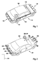
- FIG. 1 is a schematic representation of a vehicle 100 with a known wired parking assistance system 101.
- a central control unit 102 is designed as a parking assistant.
- the control unit 102 may be part of an ECU ("Electronic Control Unit"), for example.
- the control unit 102 is connected via wire lines 104 with four ultrasonic sensors 106 in the rear region of the vehicle and six ultrasonic sensors 108 in the front region and the front side region of the vehicle.
- the Wire lines 104 may directly interconnect the components or may be part of a cabling that implements a bus system, such as a Controller Area Network (CAN) bus.
- CAN Controller Area Network
- at least one output interface for example an HMI (“human-machine interface") 110, is connected to the driver via the wire lines 104 for the purpose of outputting information.
- HMI human-machine interface
- the sensors 106, 108 are simple electro-acoustic signal converters, which convert the control unit 102 via the wire lines 104 transmitted control signals into acoustic signals that are emitted in the vehicle environment. After a predetermined settling time, the same sensors serve as inverted signal transducers which receive an ultrasonic signal reflected from the environment and convert it into electrical signals. The electrical signals are transmitted via the wire lines 104 to the control unit 102 for central evaluation.
- the control unit 102 determines the elapsed time between the transmission and the reception of an ultrasonic signal time and calculates from this runtime the distance of the object from the sensor. For runtime determination, the controller 102 requires a time reference (e.g., based on a crystal oscillator) and counter based thereon, such as a timer.
- a time reference e.g., based on a crystal oscillator
- cross echoes are evaluated.
- a specific sensor is excited by the control unit for emitting an ultrasonic signal.
- This sensor and other sensors are then used to detect the reflected ultrasonic signal.
- the difference in distance to the object is determined by the different transit times required by the echo for the different sensor installation locations.
- the central control unit can then determine the spatial position to the obstacle.
- the basis for this type of directional determination is also the common time base in the control unit.
- a disadvantage of systems such as in FIG. 1 shown is the high cabling effort for connecting the plurality of sensors to the central control unit, which in turn must control one or more output components.
- Waeco has introduced the wireless parking aid MagicWatch MW2500 "in the Fermodes Lifestyle Magazine from 05 November 2009 , available at http://www.fermodes.de/autonews/ obviously/waeco-hat-die-funk-einpark Huawei-magicwatch-mw2500-vorgeber.html describes a system with several ultrasonic sensors, wirelessly to a receiver in the interior of the vehicle are connected. The system provides maneuvering security for different types of vehicles and warns the driver about acoustic signals, so it seems that a distance determination is needed. However, the system does not seem to be determining the direction.
- the second to last paragraph of the article states that the standard could also be used in automotive applications such as tire pressure monitoring and keyless entry.
- the use of ZigBee for parking assistants is not mentioned.
- an ultrasound-based measurement method is proposed in a parking assistance system of a vehicle for determining the direction of an object in a vehicle environment, comprising the following steps: emitting a measurement signal, receiving a plurality of reflections of the measurement signal by a plurality of ultrasonic sensors; and determining the direction to the object by a triangulation calculation based on the received reflections.
- each of the ultrasonic sensors operates based on an individual clock.
- the measurement is carried out in accordance with a predetermined time schedule common to the majority of the ultrasonic sensors.
- the measurement signal can be transmitted by an ultrasonic sensor involved in the measurement, an ultrasonic sensor no longer used for the reception of the reflections, or a separate ultrasonic transmitter.
- the common time schedule can be about a common Specify the time frame for the measurement of the reflections.
- the time frame for the measurement of the reflections can be dimensioned so long that each of the sensors involved in the measurement can receive reflections. Dimensioning the length of this timeframe thus determines the range of the system.
- the timing scheme may provide its own time frame for each sensor involved in the measurement to communicate its measurement result regarding received reflection to the control component. Additionally or alternatively, the time scheme may also specify a specific time frame for the transmission of the measurement signal.
- a time slot of the time schedule can be determined, for example, by specifying the control component.
- a sequence of the different time frames can be fixed and a start of an initial time frame can be predetermined by a signal of the control component to all participating sensors.
- a timing of the timing scheme can also be determined by a synchronization method for synchronization of the individual clock of the plurality of sensors with each other.
- an initial timeframe of the timing scheme may begin at some point after a successful completion of synchronization.
- the timing scheme takes into account both the emission of the measurement pulse, the measurement of reflections by a plurality of the sensors, and the transmission of the measurement results to the control component.
- a communication between the control component and the sensors may in particular include control commands of the control component to the sensors, which relate either to the timing of the timing scheme, and / or other aspects of the timing scheme, for example the beginning of the time frames for the transmission of the measurement signal, the measurement, and / or the transmission of the measurement results.
- a time frame or a plurality of time frames may, for example, also include a (new) synchronization of the sensors with each other and / or with the control component.
- the timing scheme with its sequence of predetermined time frames can either be fixed and / or can be transmitted to the sensors, for example by the control component.
- one or more sensors may receive a control signal at the beginning of a time frame. There may be a certain time frame for such control signals.
- One or more timeframes of the timetable may either have a fixed length of time or one or more timeframes may be individually set in length by the control component, for example.
- a period of time for the measurement can be set, for example as a function of a vehicle speed, just as a time frame for emitting the pulse or sending the measurement result to the control component can be set individually, optionally also individually for each sensor.
- the invention also proposes a computer program for carrying out one of the methods described herein when the computer program is executed on a programmable computer device.
- the computer device may be, for example, a parking assistant or a parking assistance system of a vehicle that is implemented on an ECU, for example.
- the computer program may be stored on a machine-readable medium, for example a permanent or rewritable medium in or in association with a programmable computer device or a CD-ROM, DVD or a USB stick. Additionally or alternatively, the computer program may be provided for download to a programmable computing device, e.g. Via a data network such as the Internet or a communication link such as a telephone line or a wireless connection.
- a parking assistance system is also proposed in a vehicle for carrying out an ultrasound-based measurement method for determining the direction of an object in a vehicle environment.
- the parking assistance system comprises the following components: a component for emitting a measurement signal; a plurality of ultrasonic sensors for receiving a plurality of reflections of the measurement signal; and a control component for determining the direction to the object by a triangulation calculation based on the received reflections.
- Each of the ultrasonic sensors is configured to operate based on an individual clock.
- the parking assistance system is designed to perform the measurement in accordance with a predetermined time schedule common to the majority of the ultrasonic sensors.
- the ultrasonic sensors can be wirelessly connected to the control component.
- the control component may be wholly or partly in a human-machine interface or a HMI be integrated. Additionally or alternatively, (parts of) the control component may be integrated in a central control unit of a parking assistance system, an ECU and / or in one of the ultrasonic sensors.
- a method for initializing a parking assist system in a vehicle having a plurality of sensors for object detection in a vehicle environment comprises the following steps: detecting, by one of the sensors, that an obstacle in a beam path of the sensor is removed; Transmitting, based on the detection, a request by the sensor to a control unit of the parking assist system; and transmitting, in response to the request, address assignment for the sensor from the control unit.
- the control unit is configured to transmit an address assignment for each of the sensors in a predefined order in accordance with a predetermined sequence in the removal of obstacles in front of the sensors.
- a parking assistance system in a vehicle having a plurality of sensors for object detection in a vehicle environment and with a control unit.
- Each of the sensors is configured to detect the removal of an obstacle in a beam path of the sensor.
- Each of the sensors is further configured to transmit, based on the detection, a request to a control unit of the parking aid system.
- the control unit is finally configured to send, in response to the request, an address allocation intended for the sensor.
- the control unit is designed to transmit an address assignment for each of the sensors in a predefined order in accordance with a predetermined sequence when removing obstacles in front of the sensors.
- the invention provides a cost-effective technique for determining direction to objects in a vehicle environment.
- the emission of a measuring pulse and the subsequent reflection measurements do not require a central clock, but are carried out with sensors, each of which has its own clock or clock generator. However, these clocks do not need to be overly precise. Instead of a central clock, a common time schedule is given.
- the central The control component only takes over the calculation of the exact distance or direction values.
- the inventive method thus also allows the use of wireless communication systems in the vehicle, in which such a close connection and control of sensors to a central control unit as in a wired system is not possible.
- the sensors can be wirelessly connected to the control component, i. it can be dispensed with elaborate wiring.
- the ultrasonic sensors only need a connection to a power supply.
- control component is integrated, for example, in an HMI, an existing central unit such as an ECU or even in one of the ultrasonic sensors.
- control component is integrated, for example, in an HMI, an existing central unit such as an ECU or even in one of the ultrasonic sensors.
- the control component is implemented depends neither on (at least partially omitted) cabling nor on the existence of a precise clock on the hardware platform on which the control component is implemented, since such is not absolutely necessary.
- a parking assistance system having a plurality of, for example, wirelessly connected sensors with regard to an address allocation can be advantageously already initialized during a vehicle production.
- the sensors can be identical parts, so need not be individualized by an address assignment in the manufacture of the sensors. This reduces the cost of building the system.
- FIG. 2 a schematically illustrated vehicle 200, a first embodiment 201 of an inventively designed parking assistant or parking assistance system.
- the parking assistant 201 has a plurality of ultrasonic sensors 202 - 205 arranged in a rear area of the vehicle and a plurality of sensors 206 arranged in a front area of the vehicle 200.
- the parking assistant 201 has an HMI 208, in which a control component 210 is integrated in the form of application software.
- a central controller similar to the ECU 102 in FIG. 1 may be present for the implementation of other driver assistance functions in the vehicle 200, but is not required for the parking assistance system 201 and therefore in the Fig. 2 Not shown.
- the ultrasonic sensors 202 - 206 are wirelessly connected to the control component 210.
- sensors 202-206 are "smart sensors" that have their own processor and clock for wireless communication as compared to conventional sensors , Due to the own processor with the corresponding ones Processing capacities and the own clock and the time base based thereon, these sensors can also independently make about a distance measurement.
- parking assistance system 201 a plurality of subsystems 202 - 205, 206, which are coordinated via the control component 210.
- the control component 201 controls, for example, a coordination of the measurement programs and an output of resulting information via the HMI 208.
- a direction measurement to at least one object in a rear surrounding area of the vehicle 200 or to at least one object in the front area can be realized, whereby such a measurement is based on a common time schedule that hold all the sensors involved, both for the implementation of the measurement and the communication of the subsystems with the control component 210 and / or each other.
- Synchronization of the sensors 202-205 or 206 with each other, as well as with the control component 210 as well as the configuration of a common timing scheme sensor, may occur on time scales typical of electromagnetic events; these timescales are usually much shorter than the distance / direction detection measuring processes whose time scales are based on the propagation time of the ultrasonic signals.
- a direction measurement to an indicated object 212 in the rear environment of the vehicle 200 is used.
- Some or all of the sensors 202-205 perform a distance measurement to the object 212.
- Each of these measurements is based on the respective, local time base of the corresponding sensor; a synchronization or cross-sensor, ie common time scheme is not mandatory for this purpose.
- the time bases of all included sensors must be synchronized.
- a measuring method for determining the direction to the object 212 can then be carried out. In this case, one of the sensors transmits a measuring pulse (ultrasonic signal) at a specific instant given by a common time scheme.
- a measurement result may, for example, relate to a representation of an echo measured on the basis of the respective local time base, a measured transit time or already a calculated distance.
- FIG. 3 is a schematic representation of the rear sensors 202 - 205 and the control component 210 from Fig. 2 , wherein functional units of the sensor 202 and the control component 210 are outlined.
- the sensors may have the same units as shown for the sensor 202.
- An acoustic output unit, namely a speaker 302, and an optical output unit, namely a display element 304, of the HMI 208 are also indicated.
- the ultrasonic sensor 202 includes a control module (controller) 310, an ultrasonic transmitter 312, an ultrasonic receiver 314, a timer 316, and a communication module 318 for wireless communication with the control component 210.
- Ultrasonic transmitters 312 and receivers 314 may also be integrated, for example, in shape a piezoelectric transducer or other electro-acoustic transducer.
- the clock 316 may be a quartz crystal or other clock generator as known in the art of processor technology.
- the communication module 318 may be based on wireless communication technology such as WLAN, DECT, HiperLAN, Bluetooth, or ZigBee.
- the control component 210 has a control module (controller) 330, a communication module 332, a clock generator 334, and an output module 336.
- the communication module 332 is for communication with the communication module 318 of the sensor 202 and the corresponding communication modules (not shown) of the further sensors 203 - 205 trained.
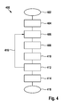
- the method 400 is used (402) to perform an ultrasound-based measurement for determining the direction of the object 212.
- the sensors 202-205 are synchronized with the control component 210. More specifically, the sensors 202-205 and the control component 210 are synchronized to a common time base so that they can communicate without collision. Such methods for wireless systems are usually carried out in the so-called "media access layer" and are known as such. Usually, synchronization messages are sent out by a common master, for example so-called SYNC beacons. The other communication users adjust their internal timing based on these messages. With FlexRay bus systems, a multi-master solution is also realized.
- at least two nodes of the communication network transmit SYNC frames as synchronization messages. Each node in the network measures the time between two SYNC frames and adjusts its own internal clock (Clock) according to speed (rate) and absolute time (offset) accordingly.
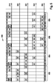
- the measuring method 400 runs according to an in FIG. 5 illustrated timing 500, which relates to the control component 210 and the sensors 202-205.
- a measurement procedure comprises one or more time frame blocks 502-508, each frame block again comprising a plurality of time frames.
- the frame block 502 includes the time frames 510-518, the frame block 504 the time frames 520-530, etc.
- the frame blocks may be of different length, ie, comprise different many time frames, but the time frames all have the same time length. In other embodiments, the time frames may have different lengths of time.
- step 406 Fig. 4
- the control component 210 sends to the sensors 202 and 203 via the communication module 332 a corresponding request message (ST, "Start Measurement").
- ST request message
- This initialization message ST is created in the control component 210 by the control module 330, for example based on information on the common time scheme 500 stored in a memory 338.
- Each first time frame of a frame block is used to transmit control messages to the sensors, therefore all sensors in the time frame 510 are in receipt.
- the message ST is addressed by means of a suitable address information to the sensors 202 and 203, which receive the message ST (RT, "Receive Trigger"); the sensors 204, 205 and 206 also receive the message ST, but do not process them further.
- the message ST is received by the communication module 318, detected as directed to the sensor 202 and then forwarded to the control module 310, where the specifications of the message ST, for example.
- an internal scheduling are taken over, which relate to steps to be performed in the subsequent timeframe of the frame block 502.
- the message ST may, for example, contain a specification as to which of the sensors should emit a measuring pulse, in which time frame which sensors should be ready to receive the echo, etc.
- a specification as to which of the sensors should emit a measuring pulse in which time frame which sensors should be ready to receive the echo, etc.
- variable time frames it is also possible, for example, to specify a length of the subsequent time frames.
- the initialization message ST can also be used in addition to or as an alternative to a synchronization of the internal clock generator 316 of the sensor 202 carried out in the MAC layer with the clock generator 334 of the control component 210. It is essential that for the measurement performed in the frame block 502, the ultrasonic sensors 202 and 203 operate on a common time base, so that a transit time measurement for the measured signal emitted by the sensor 202 and the reflection received by the sensor 203 is possible.
- time frame 512 in response to a corresponding instruction in the message ST, the sensor 202 sends out an ultrasound measurement pulse (SI, "sent out pulse”).
- SI ultrasound measurement pulse
- the ultrasonic sensors 202 and 203 receive in the time frame 514 (step 410) reflections of the previously transmitted measurement pulse (RE, "receive echo”).
- the other sensors 204, 205 and 206 do not participate in the measurement described herein, which does not preclude their being prompted by the control component 210 for other actions, such as distance measurements or other directional measurement.
- These further actions can be adapted to the in FIG. 5 outlined timetables 500 may or may be based on one or more other schedules; Such a time scheme may, for example, be valid only for a single sensor.
- the instructions for such other actions can also be transmitted in the time frame 510 with the message ST or other control messages to the other sensors (in the former case, then the message ST, in contrast to the above discussed, in addition to the sensors 202 and 203 also to other sensors directed).
- step 412 which extends over the time frames 516 and 518, the measurement results of the sensors 202 and 203 are communicated to the control component 210.
- the control module 310 evaluates the received in the time frame 514 from the receiver 314 signal (RE, "Receive Echo") on the presence of an echo and determines therefrom a result which, for example, can be temporarily stored in memory 320.
- the transit time of the signal here corresponds to a time measured based on the internal clock 316, which has elapsed between the transmission of the measuring pulse by the transmitter 312 and the reception of an echo by the receiver 314.
- the control module 310 may buffer the measured travel time and / or the calculated distance. This measurement result is then read in the time frame 516 from the buffer memory 320 and transmitted via the communication module 318 wirelessly to the control component 210.
- the sensor 202 sends its results (SR, "Send Result", RR, "Receive Result"), then in the time frame 518 the sensor 203.
- the control component 210 receives with the communication module 332 stores the messages SR and stores them in a buffer 338, for example.
- the measurement results can be stored in association with the respective installation location of the sensors 202 and 203, which is important for subsequent triangulation calculation (step 414) for determining the direction to the detected object 121.
- the frame block 502 ends.
- Further measurements are performed in frame blocks 504, 506 and 508.
- steps 406-412 are repeated analogously with respective other sensors along the rearward front of vehicle 200, as indicated by arrow 416 in FIG Fig. 4 indicated.
- Each of the frame blocks 502, 504, 506, 508 includes a time frame 510, 520, 532, 544 for transmitting the initialization message.
- multiple frame blocks may also together have only one initialization time frame in which control information is transmitted for multiple frame blocks.
- Each of the frame blocks 502, 504, 506, 508 comprises a further time frame 512, 522, 534, 546 for transmitting the measurement signal, and a subsequent time frame for detecting any reflections (RE) present.
- This time frame RE is dimensioned so long that all detectors can receive reflections within this time frame. The length of this time frame thus determines the maximum possible running time and thus the effective range of the system.
- the timeframe RE may differ, unlike in Fig. 5 shown to be longer or shorter than the other time frame.
- the time frame RE can also have different lengths in successive frame blocks.
- the time frame RE can, for example, be matched to an object previously detected.
- Each frame block 502, 504, 506, 508 includes as many time frames SR as necessary to transmit the measurement results, so frame blocks 502 and 508 comprise two time frames RR 516 and 518 and 550 and 552, respectively.
- Frame blocks 504 and 506 each include three time frames RR 526, 528, 530 and 538, 540, 542, respectively.
- the measurement results transmitted in the time frame SR may, for example, only include a time stamp if the clocks of the sensors were, for example, synchronized to a common offset. From the time stamp of the transmitting sensor and the time stamps of the receiving sensors, the transit time and thus the distance to the object 212 can then be determined for each sensor location. Alternatively or additionally, the measurement results may also contain information about the runtime or already calculated distance.
- the transmitted measurement results can also carry the address of the respective sensor; however, this is not absolutely necessary if, based on the common time scheme made known in the initialization messages ST, it is known in each time frame SR which sensor has to send.
- the control component 210 calculates the direction to the detected object 212 by a triangulation calculation. Such a calculation may be performed after each of the frame blocks 502, 504, 506, 508 and / or may be performed after completely traversing the series of measurements described by these frame blocks.
- the control module 330 extracts the measurement results from the buffer 338 in association with the respective sensor or its installation location. The distances are calculated from the transmitted transit times unless distance values have already been transmitted (if necessary, the transmitted distance values are still corrected, for example based on the time base 334, if this is more precise than the local time bases of the sensors). From the distances and the known installation locations, the direction to the object 212 is then calculated by means of triangulation.
- the measurement result is then output acoustically via the loudspeaker 302 and possibly also optically via the display 304. This completes the process (step 418), however, the method 400 may be continuously repeated on the basis of the time schedule 500 to continuously monitor the rearward area of the vehicle 200 for obstacles, for example in a parking situation.
- Timing 500 may be specified by control component 210 by communicating information in messages ST to the respective sensors. Without a transmission of such information, for example, a predetermined default scheme could be run through.
- a time scheme for the parking system 201 may be fixed by the scheme in the control modules in the control component, but also the sensors is fixed, eg. By programming from the factory.
- the timing scheme is controlled by the control component of the parking system, this could include a situational change such as the length of time frames or the number of receiving sensors. For example, more sensors could be added to increase accuracy (however, due to the additional time frame SR / RR, the frame blocks would lengthen accordingly, ie the refresh rate would be reduced).
- Such an adjustment of the time schedule can be carried out, for example, as a function of one or more detected objects, other properties of the vehicle environment, a speed of the vehicle, etc.
- FIG. 6 shows a further embodiment of a parking aid system 602 according to the invention in a vehicle 600.
- a plurality of sensors 604 in a rear area of the vehicle 600 and a plurality of sensors 606 in a front area of the vehicle 600 are also wirelessly connected to a control component 610.
- the control component 610 is implemented in a central controller 608.
- the controller 608 may include, for example, an ECU that controls a variety of other assistance functions in the vehicle 600.
- the control component 610 is connected to an HMI 614 via a general CAN bus 612 of the vehicle 600.
- the CAN bus 612 is anyway required between ECU 608 and HMI 614 for other assistance functions, so that no additional expenditure in the form of cabling or other hardware units is required for the parking aid system according to the invention.
- Embodiment 600 shows the conventionally required wiring between sensors 604, 606 and control component 610. Carrying out distance measurements and direction determinations of objects or obstacles in an environment of vehicle 600 may be performed by parking system 600 in the same way as described above System 200's FIGS. 2 to 5 was discussed.
- control component for coordinating the sensor subsystems is integrated in one of the ultrasonic sensors.
- functionality of the control component can also be implemented distributed.
- a group of sensors which includes, for example, the sensors in a rear area of a vehicle, transmit their measurement results in the form of time stamps to one of the sensors from the group, which calculates running times and / or distances from this.
- These results would then be transmitted wirelessly or by wire from the sensor to a computing unit in an HMI or ECU, where triangulation calculations would then be made for direction determination.
- triangulation calculations would then be made for direction determination.
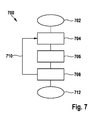
- FIG. 7 is a flow chart illustrating a method 700 for initializing the in FIG. 2
- the method 700 particularly relates to an address allocation required for the wireless control of the sensors 202 - 205, 206.
- an individual address assignment is already possible during the manufacture of the sensors.
- a complex storage would be required with the management of appropriate parts lists. Possibly.
- the right sensors are always installed in the correct installation locations. To avoid such, costly effort, it is advantageous if the sensors are designed as identical parts, ie as identical parts that have either no address or all the same address in their manufacture and installation.
- the method 700 starts from sensors installed as identical parts and describes how an initial address assignment takes place to the sensors already installed in the vehicle and connected to the on-board supply (702).
- Each of the sensors 202-205, 206 is configured to passively behave as long as there is an obstacle in the beam path that is less than a predetermined minimum distance.
- the minimum distance is chosen so that the sensor remains passive, as long as an obstacle is located directly on the sensor, for example in the form of a built-in protection over the bumper, in which the sensor is installed, a protective cover or the like.
- the passive behavior comprises in particular that no messages are yet to be sent via the wireless communication module 318.
- step 704 the sensor 202 (FIG. FIGS. 2 . 3 ) detects a distance of an obstacle in the beam path of the transmitter 312 by the receiver 314.
- step 706 in response to the obstacle distance detected in step 704, from the sensor 202 via the communication module 318, a wireless message is sent to a control component, ie, to the control component 210.
- the message contains an address request.
- address request messages are known from wireless but also wired networks.
- the control component 210 receives the request message and, in response to this request, sends an address award message indicating the address assigned to the sensor 202 in step 708.
- the message is received only by the sensor 202, since the other sensors passively behave due to the obstacle still in their beam path.
- the sensor 202 stores the address in order to be able to recognize future messages intended for the sensor 202 and to add these transmitted messages as the sender address.
- this method can be used for other or all sensors in the vehicle 201 in FIG. 2 are installed, repeat.
- the procedure for address assignment ends in step 712. It can, for example, be run through again for the front-side sensors.
- method 700 it is necessary that only one sensor be triggered simultaneously by removing an obstacle, send an address request, and store the address received in response. This can for example be achieved in that the obstacle is a coherent object such as a bumper protective film, which is gradually withdrawn and gradually releases the beam path of the sensors installed in the bumper.
- the sensors are exposed and therefore send an address request, always the same (alternatively, a process would be conceivable in which the sensors measure a number of cross echoes in front of a defined obstacle, and the control component in retrospect, determine the installation locations of the sensors).
- the addresses in the control component may be fixedly assigned to an installation location, and the control component assigns the addresses in turn.
- the address assignment to the sensors is thus translated into a predetermined sequence in the removal of an obstacle or multiple obstacles in the beam path of the built-in sensors.
- Such a predefined order in the removal of obstacles in the usually highly standardized manufacturing process of vehicles (mass production) anyway the rule.
- the sensors are first installed in the bumper and connected to the power supply in the vehicle.
- a film an adhesive tape or the like.
- the film also serves as an obstacle in the beam path of the sensors, so that they behave passively, as long as the obstacle is in the beam path.
- the tape is peeled off from one side of the bumper to the other, starting from a predefined point. This will remove the obstruction in the beam path of the sensors one sensor at a time.
- the peeling off of the film takes place slowly in comparison to the address allocation method described above.
- Wireless communication between the sensor and the control component takes place within a few or at most tens of milliseconds.
- stripping a film may require a time in the range of one second. For a defined address assignment is It then still advantageous if the film is always removed in all vehicles (for example, a series) in the same way.
- the central control component occasionally checks, for example when starting the vehicle, whether all sensors are present and functioning. This could be done in a special monitoring mode in which messages addressed to each individual sensor are sent out; If there is no feedback from a sensor, the relevant sensor is defective or has been replaced. If only a single sensor does not react, for example, by sending an address assignment message with the missing address, it can be assigned to the new sensor, which is in an initial mode; the other sensors would discard the message because they have a valid address. If there is no reaction to the transmission of an address assignment message, or reactions from several sensors occur because a plurality of sensors has been exchanged, an error message can be output, for example, or when replacing a plurality of sensors, the initialization method described above can be carried out.
- the methods described herein may generally be implemented in the form of hardware circuits, software, for example in conjunction with a programmable microprocessor, an application specific integrated circuit (ASIC), and / or one or more digital signal processors (DSP).
- Software coding of the methods described herein can be stored, for example, in a random access memory (RAM) or a read-only memory (ROM), for example an Erasable Programmable ROM (EPROM) or a comparable semi-permanent or permanent storage medium.
Applications Claiming Priority (1)
| Application Number | Priority Date | Filing Date | Title |
|---|---|---|---|
| DE102010044031A DE102010044031A1 (de) | 2010-11-17 | 2010-11-17 | Ultraschallbasierte Richtungsbestimmung von Objekten in einer Fahrzeugumgebung |
Publications (1)
| Publication Number | Publication Date |
|---|---|
| EP2455779A1 true EP2455779A1 (fr) | 2012-05-23 |
Family
ID=44772881
Family Applications (1)
| Application Number | Title | Priority Date | Filing Date |
|---|---|---|---|
| EP11184296A Withdrawn EP2455779A1 (fr) | 2010-11-17 | 2011-10-07 | Détermination de la direction à base d'ultrasons d'objets dans un environnement de véhicule |
Country Status (2)
| Country | Link |
|---|---|
| EP (1) | EP2455779A1 (fr) |
| DE (1) | DE102010044031A1 (fr) |
Cited By (6)
| Publication number | Priority date | Publication date | Assignee | Title |
|---|---|---|---|---|
| EP2549295A3 (fr) * | 2011-07-16 | 2014-03-19 | Valeo Schalter und Sensoren GmbH | Dispositif de capteur pour un véhicule automobile, véhicule automobile et procédé de fonctionnement d'au moins deux capteurs dans un véhicule automobile |
| WO2014086647A1 (fr) * | 2012-12-04 | 2014-06-12 | Valeo Schalter Und Sensoren Gmbh | Procédé de synchronisation de capteurs sur un bus de données |
| EP2821807A2 (fr) | 2013-07-03 | 2015-01-07 | Volkswagen Aktiengesellschaft | Déterminer une position d'un dispositif associé à un véhicule |
| WO2018210966A1 (fr) | 2017-05-16 | 2018-11-22 | Elmos Semiconductor Aktiengesellschaft | Procédé de transmission de données via un bus de données de véhicule d'un système à ultrasons à un dispositif de traitement de données |
| WO2019192762A1 (fr) * | 2018-04-05 | 2019-10-10 | Robert Bosch Gmbh | Sonde radar d'un système radar |
| WO2024012638A1 (fr) * | 2022-07-14 | 2024-01-18 | Continental Autonomous Mobility Germany GmbH | Dispositif de détection, véhicule et procédé de fonctionnement d'un dispositif de détection |
Families Citing this family (5)
| Publication number | Priority date | Publication date | Assignee | Title |
|---|---|---|---|---|
| DE102012212260A1 (de) * | 2012-07-13 | 2014-01-16 | Continental Automotive Gmbh | Verfahren und Vorrichtung zur Steuerung eines Fahrerassistenzsystems eines Fahrzeugs |
| DE102013208415B4 (de) | 2013-05-07 | 2023-12-28 | Carl Zeiss Microscopy Gmbh | Mikroskop und Verfahren für die 3D-hochauflösende Lokalisierungsmikroskopie |
| DE102013208926A1 (de) | 2013-05-14 | 2014-11-20 | Carl Zeiss Microscopy Gmbh | Verfahren zur 3D-hochauflösenden Lokalisierungsmikroskopie |
| DE102013208927A1 (de) | 2013-05-14 | 2014-11-20 | Carl Zeiss Microscopy Gmbh | Verfahren zur 3D-hochauflösenden Lokalisierungsmikroskopie |
| DE102017121302A1 (de) | 2017-09-14 | 2019-03-14 | Knorr-Bremse Systeme für Nutzfahrzeuge GmbH | Rückfahrassistenzsystem und ein Verfahren zur Rückfahrunterstützung |
Citations (2)
| Publication number | Priority date | Publication date | Assignee | Title |
|---|---|---|---|---|
| US20060119473A1 (en) * | 1998-08-06 | 2006-06-08 | Altra Technologies Incorporated | System and method of avoiding collisions |
| DE102008045190A1 (de) * | 2008-08-30 | 2010-03-04 | Valeo Schalter Und Sensoren Gmbh | Verfahren zur Steuerung von Sensoren an einem Fahrzeug |
Family Cites Families (3)
| Publication number | Priority date | Publication date | Assignee | Title |
|---|---|---|---|---|
| DE10360889A1 (de) * | 2003-12-19 | 2005-07-14 | Robert Bosch Gmbh | System mit zwei oder mehr Sensoren |
| DE102008000690A1 (de) * | 2008-03-14 | 2009-09-17 | Robert Bosch Gmbh | Adressierung von Sende- und Empfangseinheiten einer Ultraschallabstandsmesseinrichtung |
| JP4826615B2 (ja) * | 2008-09-30 | 2011-11-30 | パナソニック電工株式会社 | 車両用周辺監視装置 |
-
2010
- 2010-11-17 DE DE102010044031A patent/DE102010044031A1/de not_active Withdrawn
-
2011
- 2011-10-07 EP EP11184296A patent/EP2455779A1/fr not_active Withdrawn
Patent Citations (2)
| Publication number | Priority date | Publication date | Assignee | Title |
|---|---|---|---|---|
| US20060119473A1 (en) * | 1998-08-06 | 2006-06-08 | Altra Technologies Incorporated | System and method of avoiding collisions |
| DE102008045190A1 (de) * | 2008-08-30 | 2010-03-04 | Valeo Schalter Und Sensoren Gmbh | Verfahren zur Steuerung von Sensoren an einem Fahrzeug |
Non-Patent Citations (4)
| Title |
|---|
| "Waeco hat die Funk Einparkhilfe MagicWatch MW2500 vorgestellt", FERMODES LIFESTYLE MAGAZIN, 5 November 2009 (2009-11-05), Retrieved from the Internet <URL:www.fermodes.de/autonews/artikel/waeco-hat-die-funk-einparkhilfe-magicwatch- mw2500-vorgestellt.html> |
| ANONYMOUS: "Waeco hat die Funk Einparkhilfe MagicWatch MW2500 vorgestellt", INTERNET CITATION, 10 September 2006 (2006-09-10), pages 1 - 3, XP007919916, Retrieved from the Internet <URL:http://www.fermodes.de/autonews/artikel/waeco-hat-die-funk-einparkhi ... 1 of> [retrieved on 20111209] * |
| GARY LEGG: "ZigBee: Wireless Technology for Low-Power Sensor Networks", TECHONLINE, 6 May 2004 (2004-05-06), Retrieved from the Internet <URL:www.commsdesign.com/showArtic!e.jhtm!?artic!e!D=192200323> |
| LEGG G: "ZigBee: Wireless Technology for Low-Power Sensor Networks", INTERNET CITATION, 6 May 2004 (2004-05-06), pages 1 - 5, XP007919915, Retrieved from the Internet <URL:http://www.eetimes.com/General/PrintView/4017853 1 of> [retrieved on 20111213] * |
Cited By (12)
| Publication number | Priority date | Publication date | Assignee | Title |
|---|---|---|---|---|
| EP2549295A3 (fr) * | 2011-07-16 | 2014-03-19 | Valeo Schalter und Sensoren GmbH | Dispositif de capteur pour un véhicule automobile, véhicule automobile et procédé de fonctionnement d'au moins deux capteurs dans un véhicule automobile |
| WO2014086647A1 (fr) * | 2012-12-04 | 2014-06-12 | Valeo Schalter Und Sensoren Gmbh | Procédé de synchronisation de capteurs sur un bus de données |
| EP2821807A2 (fr) | 2013-07-03 | 2015-01-07 | Volkswagen Aktiengesellschaft | Déterminer une position d'un dispositif associé à un véhicule |
| DE102013213029A1 (de) | 2013-07-03 | 2015-01-08 | Volkswagen Aktiengesellschaft | Bestimmen einer Position einer einem Fahrzeug zugeordneten Vorrichtung |
| WO2018210966A1 (fr) | 2017-05-16 | 2018-11-22 | Elmos Semiconductor Aktiengesellschaft | Procédé de transmission de données via un bus de données de véhicule d'un système à ultrasons à un dispositif de traitement de données |
| DE112018001826B3 (de) | 2017-05-16 | 2022-10-06 | Elmos Semiconductor Se | Verfahren zur Übertragung von Daten über einen Fahrzeugdatenbus von einem Ultraschallsystem zu einer Datenverarbeitungsvorrichtung |
| DE112018001824B3 (de) | 2017-05-16 | 2022-12-08 | Elmos Semiconductor Se | Verfahren zur Übertragung von Daten über einen Fahrzeugdatenbus von einem Ultraschallsystem zu einer Datenverarbeitungsvorrichtung |
| DE112018001823B3 (de) | 2017-05-16 | 2023-04-13 | Elmos Semiconductor Se | Verfahren zur Übertragung von Daten über einen Fahrzeugdatenbus von einem Ultraschallsystem zu einer Datenverarbeitungsvorrichtung |
| US11719785B2 (en) | 2017-05-16 | 2023-08-08 | Elmos Semiconductor Se | Transmitting ultrasonic signal data |
| WO2019192762A1 (fr) * | 2018-04-05 | 2019-10-10 | Robert Bosch Gmbh | Sonde radar d'un système radar |
| CN111936881A (zh) * | 2018-04-05 | 2020-11-13 | 罗伯特·博世有限公司 | 用于雷达系统的雷达传感器头 |
| WO2024012638A1 (fr) * | 2022-07-14 | 2024-01-18 | Continental Autonomous Mobility Germany GmbH | Dispositif de détection, véhicule et procédé de fonctionnement d'un dispositif de détection |
Also Published As
| Publication number | Publication date |
|---|---|
| DE102010044031A1 (de) | 2012-05-24 |
Similar Documents
| Publication | Publication Date | Title |
|---|---|---|
| EP2455779A1 (fr) | Détermination de la direction à base d'ultrasons d'objets dans un environnement de véhicule | |
| EP3145793B1 (fr) | Dispositif d'assistance au stationnement pour véhicule automobile | |
| EP3961253B1 (fr) | Procédé de connectivité au capteur | |
| EP2195683B1 (fr) | Système d'assistance à la conduite et son procédé de fonctionnement | |
| EP2263102B1 (fr) | Système d assistance au conducteur à base d ultrasons | |
| EP2081052B1 (fr) | Dispositif de détection d'un véhicule et procédé de détection correspondant | |
| EP2646846A1 (fr) | Système d'aide à la conduite pour détecter un objet dans l'environnement d'un véhicule | |
| DE102010041424A1 (de) | Verfahren zum Erfassen eines Umfelds eines Fahrzeugs | |
| DE102008009651A1 (de) | Fahrerassistenzsystem eines Fahrzeugs und entsprechendes Verfahren | |
| DE102008000571A1 (de) | Adressierung von Sende- und Empfangseinheiten einer Ultraschallabstandsmesseinrichtung | |
| EP2936199B1 (fr) | Procédé pour vérifier l'authenticité d'un capteur d'ultrasons de véhicule automobile, unité de commande, capteur d'ultrasons, dispositif à capteur d'ultrasons et véhicule automobile | |
| WO2007074003A1 (fr) | Procede pour l'etalonnage d'un systeme de capteurs | |
| WO2013120706A1 (fr) | Système d'aide à la conduite équipé d'un capteur d'ultrasons, véhicule automobile et procédé d'utilisation d'un capteur d'ultrasons | |
| EP2549295B1 (fr) | Dispositif de capteur pour un véhicule automobile, véhicule automobile et procédé de fonctionnement d'au moins deux capteurs dans un véhicule automobile | |
| EP2101190B1 (fr) | Attribution des adresses aux unités de transmission et réception d'un système à ultrasons | |
| EP2527869B1 (fr) | Dispositif de capteur pour un véhicule automobile, véhicule automobile et procédé de fonctionnement d'au moins deux capteurs dans un véhicule automobile | |
| EP2788785B1 (fr) | Système de capteurs servant à faire fonctionner un système de capteurs | |
| EP4018600B1 (fr) | Procédé de reconnaissance de la position d'un abonné au bus | |
| DE102008046171A1 (de) | Verfahren und Anordnung zur Steuerung von Sensoren an einem Fahrzeug | |
| DE102012212393A1 (de) | Vorrichtung zur Abstandsmessung mit dynamischer Zeit- und Ereignisssteuerung beim Nachrichtenaustausch | |
| DE102019216996A1 (de) | Verfahren zur Bestimmung eines Abstands zwischen einem Kraftfahrzeug und einem mit dem Kraftfahrzeug gekoppelten tragbaren Kommunikationsendgerät bei einem ferngesteuerten Manövriervorgang des Kraftfahrzeugs, sowie elektronisches Abstandsbestimmungssystem und Kraftfahrzeug | |
| DE112018007775B4 (de) | Steuerungsvorrichtung für objekterkennungsvorrichtung,objekterkennungsvorrichtung und objekterkennungsprogramm | |
| WO2009118061A1 (fr) | Adressage d’unités émettrices et réceptrices d’une installation de mesure de distance à ultrasons | |
| EP2433151B1 (fr) | Procédé pour sélectionner certaines activités d'une pluralité de capteurs, centrale de commande, capteur et système capteur | |
| EP2901175B1 (fr) | Dispositif electronique, procede de fonctionnement pour un dispositif electronique et utilisation d'un dispositif electronique |
Legal Events
| Date | Code | Title | Description |
|---|---|---|---|
| PUAI | Public reference made under article 153(3) epc to a published international application that has entered the european phase |
Free format text: ORIGINAL CODE: 0009012 |
|
| AK | Designated contracting states |
Kind code of ref document: A1 Designated state(s): AL AT BE BG CH CY CZ DE DK EE ES FI FR GB GR HR HU IE IS IT LI LT LU LV MC MK MT NL NO PL PT RO RS SE SI SK SM TR |
|
| AX | Request for extension of the european patent |
Extension state: BA ME |
|
| STAA | Information on the status of an ep patent application or granted ep patent |
Free format text: STATUS: THE APPLICATION IS DEEMED TO BE WITHDRAWN |
|
| 18D | Application deemed to be withdrawn |
Effective date: 20121124 |