EP2455779A1 - Ultrasound-based orientation detection of objects in the vicinity of a vehicle - Google Patents
Ultrasound-based orientation detection of objects in the vicinity of a vehicle Download PDFInfo
- Publication number
- EP2455779A1 EP2455779A1 EP11184296A EP11184296A EP2455779A1 EP 2455779 A1 EP2455779 A1 EP 2455779A1 EP 11184296 A EP11184296 A EP 11184296A EP 11184296 A EP11184296 A EP 11184296A EP 2455779 A1 EP2455779 A1 EP 2455779A1
- Authority
- EP
- European Patent Office
- Prior art keywords
- sensors
- measurement
- vehicle
- sensor
- parking
- Prior art date
- Legal status (The legal status is an assumption and is not a legal conclusion. Google has not performed a legal analysis and makes no representation as to the accuracy of the status listed.)
- Withdrawn
Links
Images


Classifications
-
- G—PHYSICS
- G01—MEASURING; TESTING
- G01S—RADIO DIRECTION-FINDING; RADIO NAVIGATION; DETERMINING DISTANCE OR VELOCITY BY USE OF RADIO WAVES; LOCATING OR PRESENCE-DETECTING BY USE OF THE REFLECTION OR RERADIATION OF RADIO WAVES; ANALOGOUS ARRANGEMENTS USING OTHER WAVES
- G01S15/00—Systems using the reflection or reradiation of acoustic waves, e.g. sonar systems
- G01S15/88—Sonar systems specially adapted for specific applications
- G01S15/93—Sonar systems specially adapted for specific applications for anti-collision purposes
- G01S15/931—Sonar systems specially adapted for specific applications for anti-collision purposes of land vehicles
-
- G—PHYSICS
- G01—MEASURING; TESTING
- G01S—RADIO DIRECTION-FINDING; RADIO NAVIGATION; DETERMINING DISTANCE OR VELOCITY BY USE OF RADIO WAVES; LOCATING OR PRESENCE-DETECTING BY USE OF THE REFLECTION OR RERADIATION OF RADIO WAVES; ANALOGOUS ARRANGEMENTS USING OTHER WAVES
- G01S15/00—Systems using the reflection or reradiation of acoustic waves, e.g. sonar systems
- G01S15/003—Bistatic sonar systems; Multistatic sonar systems
-
- G—PHYSICS
- G01—MEASURING; TESTING
- G01S—RADIO DIRECTION-FINDING; RADIO NAVIGATION; DETERMINING DISTANCE OR VELOCITY BY USE OF RADIO WAVES; LOCATING OR PRESENCE-DETECTING BY USE OF THE REFLECTION OR RERADIATION OF RADIO WAVES; ANALOGOUS ARRANGEMENTS USING OTHER WAVES
- G01S15/00—Systems using the reflection or reradiation of acoustic waves, e.g. sonar systems
- G01S15/87—Combinations of sonar systems
- G01S15/876—Combination of several spaced transmitters or receivers of known location for determining the position of a transponder or a reflector
- G01S15/878—Combination of several spaced transmitters or receivers of known location for determining the position of a transponder or a reflector wherein transceivers are operated, either sequentially or simultaneously, both in bi-static and in mono-static mode, e.g. cross-echo mode
-
- G—PHYSICS
- G01—MEASURING; TESTING
- G01S—RADIO DIRECTION-FINDING; RADIO NAVIGATION; DETERMINING DISTANCE OR VELOCITY BY USE OF RADIO WAVES; LOCATING OR PRESENCE-DETECTING BY USE OF THE REFLECTION OR RERADIATION OF RADIO WAVES; ANALOGOUS ARRANGEMENTS USING OTHER WAVES
- G01S15/00—Systems using the reflection or reradiation of acoustic waves, e.g. sonar systems
- G01S15/88—Sonar systems specially adapted for specific applications
- G01S15/93—Sonar systems specially adapted for specific applications for anti-collision purposes
- G01S15/931—Sonar systems specially adapted for specific applications for anti-collision purposes of land vehicles
- G01S2015/937—Sonar systems specially adapted for specific applications for anti-collision purposes of land vehicles sensor installation details
- G01S2015/938—Sonar systems specially adapted for specific applications for anti-collision purposes of land vehicles sensor installation details in the bumper area
Definitions
- the invention relates to ultrasound-based measurement methods in a parking assistance system of a vehicle for determining the distance and direction of an object in a vehicle environment, as well as a corresponding parking assistant.
- a parking assistant or parking aid system may have a plurality of sensors; For example, four or six sensors may be disposed in a front and / or a rear portion of a vehicle.
- the sensors send out ultrasonic signals into a front or rear environment of the vehicle.
- An object in the environment reflects the signal.
- These echoes are picked up by receivers that are separate or with the ultrasound transmitters in a sensor unit.
- the electrically converted echoes are transmitted to a central control unit, which calculates distances to the object from the signals. If, for example, the object is parked in the driving tube, then the distance to this potential obstacle can be output acoustically and / or optically to the driver, for example.
- To network the sensors and the output components with the control unit a corresponding wiring is required.
- the sensors are connected via two- or three-wire cables for power supply and data communication.
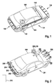
- FIG. 1 is a schematic representation of a vehicle 100 with a known wired parking assistance system 101.
- a central control unit 102 is designed as a parking assistant.
- the control unit 102 may be part of an ECU ("Electronic Control Unit"), for example.
- the control unit 102 is connected via wire lines 104 with four ultrasonic sensors 106 in the rear region of the vehicle and six ultrasonic sensors 108 in the front region and the front side region of the vehicle.
- the Wire lines 104 may directly interconnect the components or may be part of a cabling that implements a bus system, such as a Controller Area Network (CAN) bus.
- CAN Controller Area Network
- at least one output interface for example an HMI (“human-machine interface") 110, is connected to the driver via the wire lines 104 for the purpose of outputting information.
- HMI human-machine interface
- the sensors 106, 108 are simple electro-acoustic signal converters, which convert the control unit 102 via the wire lines 104 transmitted control signals into acoustic signals that are emitted in the vehicle environment. After a predetermined settling time, the same sensors serve as inverted signal transducers which receive an ultrasonic signal reflected from the environment and convert it into electrical signals. The electrical signals are transmitted via the wire lines 104 to the control unit 102 for central evaluation.
- the control unit 102 determines the elapsed time between the transmission and the reception of an ultrasonic signal time and calculates from this runtime the distance of the object from the sensor. For runtime determination, the controller 102 requires a time reference (e.g., based on a crystal oscillator) and counter based thereon, such as a timer.
- a time reference e.g., based on a crystal oscillator
- cross echoes are evaluated.
- a specific sensor is excited by the control unit for emitting an ultrasonic signal.
- This sensor and other sensors are then used to detect the reflected ultrasonic signal.
- the difference in distance to the object is determined by the different transit times required by the echo for the different sensor installation locations.
- the central control unit can then determine the spatial position to the obstacle.
- the basis for this type of directional determination is also the common time base in the control unit.
- a disadvantage of systems such as in FIG. 1 shown is the high cabling effort for connecting the plurality of sensors to the central control unit, which in turn must control one or more output components.
- Waeco has introduced the wireless parking aid MagicWatch MW2500 "in the Fermodes Lifestyle Magazine from 05 November 2009 , available at http://www.fermodes.de/autonews/ obviously/waeco-hat-die-funk-einpark Huawei-magicwatch-mw2500-vorgeber.html describes a system with several ultrasonic sensors, wirelessly to a receiver in the interior of the vehicle are connected. The system provides maneuvering security for different types of vehicles and warns the driver about acoustic signals, so it seems that a distance determination is needed. However, the system does not seem to be determining the direction.
- the second to last paragraph of the article states that the standard could also be used in automotive applications such as tire pressure monitoring and keyless entry.
- the use of ZigBee for parking assistants is not mentioned.
- an ultrasound-based measurement method is proposed in a parking assistance system of a vehicle for determining the direction of an object in a vehicle environment, comprising the following steps: emitting a measurement signal, receiving a plurality of reflections of the measurement signal by a plurality of ultrasonic sensors; and determining the direction to the object by a triangulation calculation based on the received reflections.
- each of the ultrasonic sensors operates based on an individual clock.
- the measurement is carried out in accordance with a predetermined time schedule common to the majority of the ultrasonic sensors.
- the measurement signal can be transmitted by an ultrasonic sensor involved in the measurement, an ultrasonic sensor no longer used for the reception of the reflections, or a separate ultrasonic transmitter.
- the common time schedule can be about a common Specify the time frame for the measurement of the reflections.
- the time frame for the measurement of the reflections can be dimensioned so long that each of the sensors involved in the measurement can receive reflections. Dimensioning the length of this timeframe thus determines the range of the system.
- the timing scheme may provide its own time frame for each sensor involved in the measurement to communicate its measurement result regarding received reflection to the control component. Additionally or alternatively, the time scheme may also specify a specific time frame for the transmission of the measurement signal.
- a time slot of the time schedule can be determined, for example, by specifying the control component.
- a sequence of the different time frames can be fixed and a start of an initial time frame can be predetermined by a signal of the control component to all participating sensors.
- a timing of the timing scheme can also be determined by a synchronization method for synchronization of the individual clock of the plurality of sensors with each other.
- an initial timeframe of the timing scheme may begin at some point after a successful completion of synchronization.
- the timing scheme takes into account both the emission of the measurement pulse, the measurement of reflections by a plurality of the sensors, and the transmission of the measurement results to the control component.
- a communication between the control component and the sensors may in particular include control commands of the control component to the sensors, which relate either to the timing of the timing scheme, and / or other aspects of the timing scheme, for example the beginning of the time frames for the transmission of the measurement signal, the measurement, and / or the transmission of the measurement results.
- a time frame or a plurality of time frames may, for example, also include a (new) synchronization of the sensors with each other and / or with the control component.
- the timing scheme with its sequence of predetermined time frames can either be fixed and / or can be transmitted to the sensors, for example by the control component.
- one or more sensors may receive a control signal at the beginning of a time frame. There may be a certain time frame for such control signals.
- One or more timeframes of the timetable may either have a fixed length of time or one or more timeframes may be individually set in length by the control component, for example.
- a period of time for the measurement can be set, for example as a function of a vehicle speed, just as a time frame for emitting the pulse or sending the measurement result to the control component can be set individually, optionally also individually for each sensor.
- the invention also proposes a computer program for carrying out one of the methods described herein when the computer program is executed on a programmable computer device.
- the computer device may be, for example, a parking assistant or a parking assistance system of a vehicle that is implemented on an ECU, for example.
- the computer program may be stored on a machine-readable medium, for example a permanent or rewritable medium in or in association with a programmable computer device or a CD-ROM, DVD or a USB stick. Additionally or alternatively, the computer program may be provided for download to a programmable computing device, e.g. Via a data network such as the Internet or a communication link such as a telephone line or a wireless connection.
- a parking assistance system is also proposed in a vehicle for carrying out an ultrasound-based measurement method for determining the direction of an object in a vehicle environment.
- the parking assistance system comprises the following components: a component for emitting a measurement signal; a plurality of ultrasonic sensors for receiving a plurality of reflections of the measurement signal; and a control component for determining the direction to the object by a triangulation calculation based on the received reflections.
- Each of the ultrasonic sensors is configured to operate based on an individual clock.
- the parking assistance system is designed to perform the measurement in accordance with a predetermined time schedule common to the majority of the ultrasonic sensors.
- the ultrasonic sensors can be wirelessly connected to the control component.
- the control component may be wholly or partly in a human-machine interface or a HMI be integrated. Additionally or alternatively, (parts of) the control component may be integrated in a central control unit of a parking assistance system, an ECU and / or in one of the ultrasonic sensors.
- a method for initializing a parking assist system in a vehicle having a plurality of sensors for object detection in a vehicle environment comprises the following steps: detecting, by one of the sensors, that an obstacle in a beam path of the sensor is removed; Transmitting, based on the detection, a request by the sensor to a control unit of the parking assist system; and transmitting, in response to the request, address assignment for the sensor from the control unit.
- the control unit is configured to transmit an address assignment for each of the sensors in a predefined order in accordance with a predetermined sequence in the removal of obstacles in front of the sensors.
- a parking assistance system in a vehicle having a plurality of sensors for object detection in a vehicle environment and with a control unit.
- Each of the sensors is configured to detect the removal of an obstacle in a beam path of the sensor.
- Each of the sensors is further configured to transmit, based on the detection, a request to a control unit of the parking aid system.
- the control unit is finally configured to send, in response to the request, an address allocation intended for the sensor.
- the control unit is designed to transmit an address assignment for each of the sensors in a predefined order in accordance with a predetermined sequence when removing obstacles in front of the sensors.
- the invention provides a cost-effective technique for determining direction to objects in a vehicle environment.
- the emission of a measuring pulse and the subsequent reflection measurements do not require a central clock, but are carried out with sensors, each of which has its own clock or clock generator. However, these clocks do not need to be overly precise. Instead of a central clock, a common time schedule is given.
- the central The control component only takes over the calculation of the exact distance or direction values.
- the inventive method thus also allows the use of wireless communication systems in the vehicle, in which such a close connection and control of sensors to a central control unit as in a wired system is not possible.
- the sensors can be wirelessly connected to the control component, i. it can be dispensed with elaborate wiring.
- the ultrasonic sensors only need a connection to a power supply.
- control component is integrated, for example, in an HMI, an existing central unit such as an ECU or even in one of the ultrasonic sensors.
- control component is integrated, for example, in an HMI, an existing central unit such as an ECU or even in one of the ultrasonic sensors.
- the control component is implemented depends neither on (at least partially omitted) cabling nor on the existence of a precise clock on the hardware platform on which the control component is implemented, since such is not absolutely necessary.
- a parking assistance system having a plurality of, for example, wirelessly connected sensors with regard to an address allocation can be advantageously already initialized during a vehicle production.
- the sensors can be identical parts, so need not be individualized by an address assignment in the manufacture of the sensors. This reduces the cost of building the system.
- FIG. 2 a schematically illustrated vehicle 200, a first embodiment 201 of an inventively designed parking assistant or parking assistance system.
- the parking assistant 201 has a plurality of ultrasonic sensors 202 - 205 arranged in a rear area of the vehicle and a plurality of sensors 206 arranged in a front area of the vehicle 200.
- the parking assistant 201 has an HMI 208, in which a control component 210 is integrated in the form of application software.
- a central controller similar to the ECU 102 in FIG. 1 may be present for the implementation of other driver assistance functions in the vehicle 200, but is not required for the parking assistance system 201 and therefore in the Fig. 2 Not shown.
- the ultrasonic sensors 202 - 206 are wirelessly connected to the control component 210.
- sensors 202-206 are "smart sensors" that have their own processor and clock for wireless communication as compared to conventional sensors , Due to the own processor with the corresponding ones Processing capacities and the own clock and the time base based thereon, these sensors can also independently make about a distance measurement.
- parking assistance system 201 a plurality of subsystems 202 - 205, 206, which are coordinated via the control component 210.
- the control component 201 controls, for example, a coordination of the measurement programs and an output of resulting information via the HMI 208.
- a direction measurement to at least one object in a rear surrounding area of the vehicle 200 or to at least one object in the front area can be realized, whereby such a measurement is based on a common time schedule that hold all the sensors involved, both for the implementation of the measurement and the communication of the subsystems with the control component 210 and / or each other.
- Synchronization of the sensors 202-205 or 206 with each other, as well as with the control component 210 as well as the configuration of a common timing scheme sensor, may occur on time scales typical of electromagnetic events; these timescales are usually much shorter than the distance / direction detection measuring processes whose time scales are based on the propagation time of the ultrasonic signals.
- a direction measurement to an indicated object 212 in the rear environment of the vehicle 200 is used.
- Some or all of the sensors 202-205 perform a distance measurement to the object 212.
- Each of these measurements is based on the respective, local time base of the corresponding sensor; a synchronization or cross-sensor, ie common time scheme is not mandatory for this purpose.
- the time bases of all included sensors must be synchronized.
- a measuring method for determining the direction to the object 212 can then be carried out. In this case, one of the sensors transmits a measuring pulse (ultrasonic signal) at a specific instant given by a common time scheme.
- a measurement result may, for example, relate to a representation of an echo measured on the basis of the respective local time base, a measured transit time or already a calculated distance.
- FIG. 3 is a schematic representation of the rear sensors 202 - 205 and the control component 210 from Fig. 2 , wherein functional units of the sensor 202 and the control component 210 are outlined.
- the sensors may have the same units as shown for the sensor 202.
- An acoustic output unit, namely a speaker 302, and an optical output unit, namely a display element 304, of the HMI 208 are also indicated.
- the ultrasonic sensor 202 includes a control module (controller) 310, an ultrasonic transmitter 312, an ultrasonic receiver 314, a timer 316, and a communication module 318 for wireless communication with the control component 210.
- Ultrasonic transmitters 312 and receivers 314 may also be integrated, for example, in shape a piezoelectric transducer or other electro-acoustic transducer.
- the clock 316 may be a quartz crystal or other clock generator as known in the art of processor technology.
- the communication module 318 may be based on wireless communication technology such as WLAN, DECT, HiperLAN, Bluetooth, or ZigBee.
- the control component 210 has a control module (controller) 330, a communication module 332, a clock generator 334, and an output module 336.
- the communication module 332 is for communication with the communication module 318 of the sensor 202 and the corresponding communication modules (not shown) of the further sensors 203 - 205 trained.
- the method 400 is used (402) to perform an ultrasound-based measurement for determining the direction of the object 212.
- the sensors 202-205 are synchronized with the control component 210. More specifically, the sensors 202-205 and the control component 210 are synchronized to a common time base so that they can communicate without collision. Such methods for wireless systems are usually carried out in the so-called "media access layer" and are known as such. Usually, synchronization messages are sent out by a common master, for example so-called SYNC beacons. The other communication users adjust their internal timing based on these messages. With FlexRay bus systems, a multi-master solution is also realized.
- at least two nodes of the communication network transmit SYNC frames as synchronization messages. Each node in the network measures the time between two SYNC frames and adjusts its own internal clock (Clock) according to speed (rate) and absolute time (offset) accordingly.
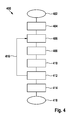
- the measuring method 400 runs according to an in FIG. 5 illustrated timing 500, which relates to the control component 210 and the sensors 202-205.
- a measurement procedure comprises one or more time frame blocks 502-508, each frame block again comprising a plurality of time frames.
- the frame block 502 includes the time frames 510-518, the frame block 504 the time frames 520-530, etc.
- the frame blocks may be of different length, ie, comprise different many time frames, but the time frames all have the same time length. In other embodiments, the time frames may have different lengths of time.
- step 406 Fig. 4
- the control component 210 sends to the sensors 202 and 203 via the communication module 332 a corresponding request message (ST, "Start Measurement").
- ST request message
- This initialization message ST is created in the control component 210 by the control module 330, for example based on information on the common time scheme 500 stored in a memory 338.
- Each first time frame of a frame block is used to transmit control messages to the sensors, therefore all sensors in the time frame 510 are in receipt.
- the message ST is addressed by means of a suitable address information to the sensors 202 and 203, which receive the message ST (RT, "Receive Trigger"); the sensors 204, 205 and 206 also receive the message ST, but do not process them further.
- the message ST is received by the communication module 318, detected as directed to the sensor 202 and then forwarded to the control module 310, where the specifications of the message ST, for example.
- an internal scheduling are taken over, which relate to steps to be performed in the subsequent timeframe of the frame block 502.
- the message ST may, for example, contain a specification as to which of the sensors should emit a measuring pulse, in which time frame which sensors should be ready to receive the echo, etc.
- a specification as to which of the sensors should emit a measuring pulse in which time frame which sensors should be ready to receive the echo, etc.
- variable time frames it is also possible, for example, to specify a length of the subsequent time frames.
- the initialization message ST can also be used in addition to or as an alternative to a synchronization of the internal clock generator 316 of the sensor 202 carried out in the MAC layer with the clock generator 334 of the control component 210. It is essential that for the measurement performed in the frame block 502, the ultrasonic sensors 202 and 203 operate on a common time base, so that a transit time measurement for the measured signal emitted by the sensor 202 and the reflection received by the sensor 203 is possible.
- time frame 512 in response to a corresponding instruction in the message ST, the sensor 202 sends out an ultrasound measurement pulse (SI, "sent out pulse”).
- SI ultrasound measurement pulse
- the ultrasonic sensors 202 and 203 receive in the time frame 514 (step 410) reflections of the previously transmitted measurement pulse (RE, "receive echo”).
- the other sensors 204, 205 and 206 do not participate in the measurement described herein, which does not preclude their being prompted by the control component 210 for other actions, such as distance measurements or other directional measurement.
- These further actions can be adapted to the in FIG. 5 outlined timetables 500 may or may be based on one or more other schedules; Such a time scheme may, for example, be valid only for a single sensor.
- the instructions for such other actions can also be transmitted in the time frame 510 with the message ST or other control messages to the other sensors (in the former case, then the message ST, in contrast to the above discussed, in addition to the sensors 202 and 203 also to other sensors directed).
- step 412 which extends over the time frames 516 and 518, the measurement results of the sensors 202 and 203 are communicated to the control component 210.
- the control module 310 evaluates the received in the time frame 514 from the receiver 314 signal (RE, "Receive Echo") on the presence of an echo and determines therefrom a result which, for example, can be temporarily stored in memory 320.
- the transit time of the signal here corresponds to a time measured based on the internal clock 316, which has elapsed between the transmission of the measuring pulse by the transmitter 312 and the reception of an echo by the receiver 314.
- the control module 310 may buffer the measured travel time and / or the calculated distance. This measurement result is then read in the time frame 516 from the buffer memory 320 and transmitted via the communication module 318 wirelessly to the control component 210.
- the sensor 202 sends its results (SR, "Send Result", RR, "Receive Result"), then in the time frame 518 the sensor 203.
- the control component 210 receives with the communication module 332 stores the messages SR and stores them in a buffer 338, for example.
- the measurement results can be stored in association with the respective installation location of the sensors 202 and 203, which is important for subsequent triangulation calculation (step 414) for determining the direction to the detected object 121.
- the frame block 502 ends.
- Further measurements are performed in frame blocks 504, 506 and 508.
- steps 406-412 are repeated analogously with respective other sensors along the rearward front of vehicle 200, as indicated by arrow 416 in FIG Fig. 4 indicated.
- Each of the frame blocks 502, 504, 506, 508 includes a time frame 510, 520, 532, 544 for transmitting the initialization message.
- multiple frame blocks may also together have only one initialization time frame in which control information is transmitted for multiple frame blocks.
- Each of the frame blocks 502, 504, 506, 508 comprises a further time frame 512, 522, 534, 546 for transmitting the measurement signal, and a subsequent time frame for detecting any reflections (RE) present.
- This time frame RE is dimensioned so long that all detectors can receive reflections within this time frame. The length of this time frame thus determines the maximum possible running time and thus the effective range of the system.
- the timeframe RE may differ, unlike in Fig. 5 shown to be longer or shorter than the other time frame.
- the time frame RE can also have different lengths in successive frame blocks.
- the time frame RE can, for example, be matched to an object previously detected.
- Each frame block 502, 504, 506, 508 includes as many time frames SR as necessary to transmit the measurement results, so frame blocks 502 and 508 comprise two time frames RR 516 and 518 and 550 and 552, respectively.
- Frame blocks 504 and 506 each include three time frames RR 526, 528, 530 and 538, 540, 542, respectively.
- the measurement results transmitted in the time frame SR may, for example, only include a time stamp if the clocks of the sensors were, for example, synchronized to a common offset. From the time stamp of the transmitting sensor and the time stamps of the receiving sensors, the transit time and thus the distance to the object 212 can then be determined for each sensor location. Alternatively or additionally, the measurement results may also contain information about the runtime or already calculated distance.
- the transmitted measurement results can also carry the address of the respective sensor; however, this is not absolutely necessary if, based on the common time scheme made known in the initialization messages ST, it is known in each time frame SR which sensor has to send.
- the control component 210 calculates the direction to the detected object 212 by a triangulation calculation. Such a calculation may be performed after each of the frame blocks 502, 504, 506, 508 and / or may be performed after completely traversing the series of measurements described by these frame blocks.
- the control module 330 extracts the measurement results from the buffer 338 in association with the respective sensor or its installation location. The distances are calculated from the transmitted transit times unless distance values have already been transmitted (if necessary, the transmitted distance values are still corrected, for example based on the time base 334, if this is more precise than the local time bases of the sensors). From the distances and the known installation locations, the direction to the object 212 is then calculated by means of triangulation.
- the measurement result is then output acoustically via the loudspeaker 302 and possibly also optically via the display 304. This completes the process (step 418), however, the method 400 may be continuously repeated on the basis of the time schedule 500 to continuously monitor the rearward area of the vehicle 200 for obstacles, for example in a parking situation.
- Timing 500 may be specified by control component 210 by communicating information in messages ST to the respective sensors. Without a transmission of such information, for example, a predetermined default scheme could be run through.
- a time scheme for the parking system 201 may be fixed by the scheme in the control modules in the control component, but also the sensors is fixed, eg. By programming from the factory.
- the timing scheme is controlled by the control component of the parking system, this could include a situational change such as the length of time frames or the number of receiving sensors. For example, more sensors could be added to increase accuracy (however, due to the additional time frame SR / RR, the frame blocks would lengthen accordingly, ie the refresh rate would be reduced).
- Such an adjustment of the time schedule can be carried out, for example, as a function of one or more detected objects, other properties of the vehicle environment, a speed of the vehicle, etc.
- FIG. 6 shows a further embodiment of a parking aid system 602 according to the invention in a vehicle 600.
- a plurality of sensors 604 in a rear area of the vehicle 600 and a plurality of sensors 606 in a front area of the vehicle 600 are also wirelessly connected to a control component 610.
- the control component 610 is implemented in a central controller 608.
- the controller 608 may include, for example, an ECU that controls a variety of other assistance functions in the vehicle 600.
- the control component 610 is connected to an HMI 614 via a general CAN bus 612 of the vehicle 600.
- the CAN bus 612 is anyway required between ECU 608 and HMI 614 for other assistance functions, so that no additional expenditure in the form of cabling or other hardware units is required for the parking aid system according to the invention.
- Embodiment 600 shows the conventionally required wiring between sensors 604, 606 and control component 610. Carrying out distance measurements and direction determinations of objects or obstacles in an environment of vehicle 600 may be performed by parking system 600 in the same way as described above System 200's FIGS. 2 to 5 was discussed.
- control component for coordinating the sensor subsystems is integrated in one of the ultrasonic sensors.
- functionality of the control component can also be implemented distributed.
- a group of sensors which includes, for example, the sensors in a rear area of a vehicle, transmit their measurement results in the form of time stamps to one of the sensors from the group, which calculates running times and / or distances from this.
- These results would then be transmitted wirelessly or by wire from the sensor to a computing unit in an HMI or ECU, where triangulation calculations would then be made for direction determination.
- triangulation calculations would then be made for direction determination.
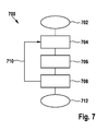
- FIG. 7 is a flow chart illustrating a method 700 for initializing the in FIG. 2
- the method 700 particularly relates to an address allocation required for the wireless control of the sensors 202 - 205, 206.
- an individual address assignment is already possible during the manufacture of the sensors.
- a complex storage would be required with the management of appropriate parts lists. Possibly.
- the right sensors are always installed in the correct installation locations. To avoid such, costly effort, it is advantageous if the sensors are designed as identical parts, ie as identical parts that have either no address or all the same address in their manufacture and installation.
- the method 700 starts from sensors installed as identical parts and describes how an initial address assignment takes place to the sensors already installed in the vehicle and connected to the on-board supply (702).
- Each of the sensors 202-205, 206 is configured to passively behave as long as there is an obstacle in the beam path that is less than a predetermined minimum distance.
- the minimum distance is chosen so that the sensor remains passive, as long as an obstacle is located directly on the sensor, for example in the form of a built-in protection over the bumper, in which the sensor is installed, a protective cover or the like.
- the passive behavior comprises in particular that no messages are yet to be sent via the wireless communication module 318.
- step 704 the sensor 202 (FIG. FIGS. 2 . 3 ) detects a distance of an obstacle in the beam path of the transmitter 312 by the receiver 314.
- step 706 in response to the obstacle distance detected in step 704, from the sensor 202 via the communication module 318, a wireless message is sent to a control component, ie, to the control component 210.
- the message contains an address request.
- address request messages are known from wireless but also wired networks.
- the control component 210 receives the request message and, in response to this request, sends an address award message indicating the address assigned to the sensor 202 in step 708.
- the message is received only by the sensor 202, since the other sensors passively behave due to the obstacle still in their beam path.
- the sensor 202 stores the address in order to be able to recognize future messages intended for the sensor 202 and to add these transmitted messages as the sender address.
- this method can be used for other or all sensors in the vehicle 201 in FIG. 2 are installed, repeat.
- the procedure for address assignment ends in step 712. It can, for example, be run through again for the front-side sensors.
- method 700 it is necessary that only one sensor be triggered simultaneously by removing an obstacle, send an address request, and store the address received in response. This can for example be achieved in that the obstacle is a coherent object such as a bumper protective film, which is gradually withdrawn and gradually releases the beam path of the sensors installed in the bumper.
- the sensors are exposed and therefore send an address request, always the same (alternatively, a process would be conceivable in which the sensors measure a number of cross echoes in front of a defined obstacle, and the control component in retrospect, determine the installation locations of the sensors).
- the addresses in the control component may be fixedly assigned to an installation location, and the control component assigns the addresses in turn.
- the address assignment to the sensors is thus translated into a predetermined sequence in the removal of an obstacle or multiple obstacles in the beam path of the built-in sensors.
- Such a predefined order in the removal of obstacles in the usually highly standardized manufacturing process of vehicles (mass production) anyway the rule.
- the sensors are first installed in the bumper and connected to the power supply in the vehicle.
- a film an adhesive tape or the like.
- the film also serves as an obstacle in the beam path of the sensors, so that they behave passively, as long as the obstacle is in the beam path.
- the tape is peeled off from one side of the bumper to the other, starting from a predefined point. This will remove the obstruction in the beam path of the sensors one sensor at a time.
- the peeling off of the film takes place slowly in comparison to the address allocation method described above.
- Wireless communication between the sensor and the control component takes place within a few or at most tens of milliseconds.
- stripping a film may require a time in the range of one second. For a defined address assignment is It then still advantageous if the film is always removed in all vehicles (for example, a series) in the same way.
- the central control component occasionally checks, for example when starting the vehicle, whether all sensors are present and functioning. This could be done in a special monitoring mode in which messages addressed to each individual sensor are sent out; If there is no feedback from a sensor, the relevant sensor is defective or has been replaced. If only a single sensor does not react, for example, by sending an address assignment message with the missing address, it can be assigned to the new sensor, which is in an initial mode; the other sensors would discard the message because they have a valid address. If there is no reaction to the transmission of an address assignment message, or reactions from several sensors occur because a plurality of sensors has been exchanged, an error message can be output, for example, or when replacing a plurality of sensors, the initialization method described above can be carried out.
- the methods described herein may generally be implemented in the form of hardware circuits, software, for example in conjunction with a programmable microprocessor, an application specific integrated circuit (ASIC), and / or one or more digital signal processors (DSP).
- Software coding of the methods described herein can be stored, for example, in a random access memory (RAM) or a read-only memory (ROM), for example an Erasable Programmable ROM (EPROM) or a comparable semi-permanent or permanent storage medium.
Abstract
Description
Die Erfindung betrifft ultraschallbasierte Messverfahren in einem Parkhilfesystem eines Fahrzeugs zur Abstands- und Richtungsbestimmung eines Objekts in einer Fahrzeugumgebung, sowie einen entsprechenden Parkassistenten.The invention relates to ultrasound-based measurement methods in a parking assistance system of a vehicle for determining the distance and direction of an object in a vehicle environment, as well as a corresponding parking assistant.
Ein Parkassistent bzw. (Ein-)Parkhilfesystem kann über eine Mehrzahl von Sensoren verfügen; beispielsweise können vier oder sechs Sensoren in einem Front- und/oder einem Heckbereich eines Fahrzeugs angeordnet sein. Von den Sensoren werden Ultraschallsignale in eine vordere bzw. rückwärtige Umgebung des Fahrzeugs ausgesendet. Ein Objekt in der Umgebung reflektiert das Signal. Diese Echos werden von Empfängern aufgenommen, die separat oder mit den Ultraschallsendern in einer Sensoreinheit vorliegen. Die elektrisch gewandelten Echos werden an ein zentrales Steuergerät übermittelt, welches aus den Signalen Abstände zum Objekt berechnet. Befindet sich das Objekt beispielsweise beim Einparken im Fahrschlauch, so kann der Abstand zu diesem potentiellen Hindernis dem Fahrer bspw. akustisch und/oder optisch ausgegeben werden. Zur Vernetzung der Sensoren und der Ausgabekomponenten mit dem Steuergerät ist eine entsprechende Verkabelung erforderlich. Meist sind die Sensoren über Zwei- oder Dreidrahtleitungen für Stromversorgung und Datenkommunikation angebunden.A parking assistant or parking aid system may have a plurality of sensors; For example, four or six sensors may be disposed in a front and / or a rear portion of a vehicle. The sensors send out ultrasonic signals into a front or rear environment of the vehicle. An object in the environment reflects the signal. These echoes are picked up by receivers that are separate or with the ultrasound transmitters in a sensor unit. The electrically converted echoes are transmitted to a central control unit, which calculates distances to the object from the signals. If, for example, the object is parked in the driving tube, then the distance to this potential obstacle can be output acoustically and / or optically to the driver, for example. To network the sensors and the output components with the control unit, a corresponding wiring is required. Usually, the sensors are connected via two- or three-wire cables for power supply and data communication.
Die Sensoren 106, 108 sind einfache elektro-akustische Signalwandler, welche vom Steuergerät 102 über die Drahtleitungen 104 übermittelten Steuersignale in akustische Signale umwandeln, die in die Fahrzeugumgebung ausgesendet werden. Nach einer vorgegebenen Ausschwingzeit dienen dieselben Sensoren als umgekehrte Signalwandler, die ein aus der Umgebung reflektiertes Ultraschallsignal empfangen und es in elektrische Signale umwandeln. Die elektrischen Signale werden über die Drahtleitungen 104 an das Steuergerät 102 zur zentralen Auswertung übermittelt.The
Zur Bestimmung des Abstandes zu einem Objekt in der Fahrzeugumgebung bestimmt das Steuergerät 102 die zwischen dem Aussenden und dem Empfangen eines Ultraschallsignals verstrichene Zeit und berechnet aus dieser Laufzeit den Abstand des Objekts vom Sensor. Für die Laufzeitbestimmung benötigt das Steuergerät 102 eine Zeitreferenz bzw. einen Taktgeber (z.B. auf Basis eines Schwingquarzes) und eine hierauf basierende Zähleinrichtung, bspw. einen Timer.To determine the distance to an object in the vehicle environment, the
Um auch die Richtung zu einem potentiellen Hindernis bestimmen zu können, werden soggenannte Kreuzechos ausgewertet. Hierbei wird ein bestimmter Sensor durch das Steuergerät zum Aussenden eines Ultraschallsignals angeregt. Dieser Sensor sowie weitere Sensoren werden danach zur Detektion des reflektierten Ultraschallsignals verwendet. Über die unterschiedlichen Laufzeiten, die das Echo zu den unterschiedlichen Sensoreinbauorten benötigt, wird die jeweils unterschiedlich Distanz zum Objekt ermittelt. Über trigonometrische Berechnungen kann das zentrale Steuergerät dann die räumliche Lage zum Hindernis ermitteln. Grundlage für diese Art der Richtungsbestimmung ist auch hier die gemeinsame Zeitbasis im Steuergerät.In order to determine the direction to a potential obstacle, so-called cross echoes are evaluated. In this case, a specific sensor is excited by the control unit for emitting an ultrasonic signal. This sensor and other sensors are then used to detect the reflected ultrasonic signal. The difference in distance to the object is determined by the different transit times required by the echo for the different sensor installation locations. Using trigonometric calculations, the central control unit can then determine the spatial position to the obstacle. The basis for this type of directional determination is also the common time base in the control unit.
Nachteilig an Systemen wie dem in
Der Artikel "
Der Artikel "
Erfindungsgemäß wird ein ultraschallbasiertes Messverfahren in einem Parkhilfesystem eines Fahrzeugs zur Richtungsbestimmung eines Objekts in einer Fahrzeugumgebung vorgeschlagen, welches die folgenden Schritte aufweist: Aussenden eines Messsignals, Empfangen mehrerer Reflektionen des Messsignals durch eine Mehrzahl von Ultraschallsensoren; und Bestimmen der Richtung zum Objekt durch eine Triangulationsberechnung basierend auf den empfangenen Reflektionen. Hierbei arbeitet jeder der Ultraschallsensoren basierend auf einem individuellen Taktgeber. Die Messung wird gemäß einem für die Mehrzahl der Ultraschallsensoren gemeinsamen, vorgegebenen Zeitschema durchgeführt. Das Messsignal kann dabei durch einen an der Messung beteiligten Ultraschallsensor, einen nicht mehr für den Empfang der Reflektionen verwendeten Ultraschallsensor oder einen separaten Ultraschallsender ausgesendet werden.According to the invention, an ultrasound-based measurement method is proposed in a parking assistance system of a vehicle for determining the direction of an object in a vehicle environment, comprising the following steps: emitting a measurement signal, receiving a plurality of reflections of the measurement signal by a plurality of ultrasonic sensors; and determining the direction to the object by a triangulation calculation based on the received reflections. Here, each of the ultrasonic sensors operates based on an individual clock. The measurement is carried out in accordance with a predetermined time schedule common to the majority of the ultrasonic sensors. The measurement signal can be transmitted by an ultrasonic sensor involved in the measurement, an ultrasonic sensor no longer used for the reception of the reflections, or a separate ultrasonic transmitter.
Insbesondere kann die Kommunikation zwischen einer die Triangulationsberechnung vornehmenden Steuerkomponente und den Ultraschallsensoren gemäß dem vorgegebenen Zeitschema ablaufen. Das gemeinsame Zeitschema kann etwa einen gemeinsamen Zeitrahmen für die Messung der Reflektionen vorgeben. Der Zeitrahmen für die Messung der Reflektionen kann so lang bemessen sein, dass jeder der an der Messung beteiligten Sensoren Reflektionen empfangen kann. Durch die Bemessung der Länge dieses Zeitrahmens wird somit die Reichweite des Systems festgelegt.In particular, the communication between a triangulation calculation performing control component and the ultrasonic sensors according to the predetermined timing scheme run. The common time schedule can be about a common Specify the time frame for the measurement of the reflections. The time frame for the measurement of the reflections can be dimensioned so long that each of the sensors involved in the measurement can receive reflections. Dimensioning the length of this timeframe thus determines the range of the system.
Das Zeitschema kann einen eigenen Zeitrahmen für jeden an der Messung beteiligten Sensor zur Übermittlung seines Messergebnisses betreffend eine empfangene Reflexion an die Steuerkomponente vorsehen. Zusätzlich oder alternativ kann das Zeitschema auch einen bestimmten Zeitrahmen zur Aussendung des Messsignals vorgeben.The timing scheme may provide its own time frame for each sensor involved in the measurement to communicate its measurement result regarding received reflection to the control component. Additionally or alternatively, the time scheme may also specify a specific time frame for the transmission of the measurement signal.
Eine Zeitlage des Zeitschemas kann etwa durch eine Vorgabe der Steuerkomponente festgelegt werden. So kann eine Abfolge der unterschiedlichen Zeitrahmen fest vorgegeben sein und ein Beginn eines anfänglichen Zeitrahmens kann durch ein Signal der Steuerkomponente an alle beteiligten Sensoren vorgegeben werden. Zusätzlich oder alternativ kann eine Zeitlage des Zeitschemas auch durch ein Synchronisationsverfahren zur Synchronisation der individuellen Taktgeber der Mehrzahl an Sensoren untereinander festgelegt werden. So kann ein anfänglicher Zeitrahmen des Zeitschemas zu einem bestimmten Zeitpunkt nach einer erfolgreich abgeschlossenen Synchronisation beginnen. Bei einer bestimmten Ausführungsform berücksichtigt das Zeitschema sowohl das Aussenden des Messimpulses, die Messung von Reflexionen durch mehrere der Sensoren, und die Übermittlung der Messergebnisse an die Steuerkomponente.A time slot of the time schedule can be determined, for example, by specifying the control component. Thus, a sequence of the different time frames can be fixed and a start of an initial time frame can be predetermined by a signal of the control component to all participating sensors. Additionally or alternatively, a timing of the timing scheme can also be determined by a synchronization method for synchronization of the individual clock of the plurality of sensors with each other. Thus, an initial timeframe of the timing scheme may begin at some point after a successful completion of synchronization. In a particular embodiment, the timing scheme takes into account both the emission of the measurement pulse, the measurement of reflections by a plurality of the sensors, and the transmission of the measurement results to the control component.
Eine Kommunikation zwischen der Steuerkomponente und den Sensoren kann insbesondere Steuerbefehle der Steuerkomponente an die Sensoren beinhalten, die entweder die Zeitlage des Zeitschemas betreffen, und/oder weitere Aspekte des Zeitschemas, beispielsweise den Beginn der Zeitrahmen für das Aussenden des Messsignals, die Messung, und / oder die Übermittlung der Messergebnisse. Ein Zeitrahmen oder mehrere Zeitrahmen können beispielsweise auch eine (Neu-)Synchronisierung der Sensoren untereinander und/oder mit der Steuerkomponente beinhalten.A communication between the control component and the sensors may in particular include control commands of the control component to the sensors, which relate either to the timing of the timing scheme, and / or other aspects of the timing scheme, for example the beginning of the time frames for the transmission of the measurement signal, the measurement, and / or the transmission of the measurement results. A time frame or a plurality of time frames may, for example, also include a (new) synchronization of the sensors with each other and / or with the control component.
Das Zeitschema mit seiner Abfolge von vorgegebenen Zeitrahmen kann entweder fest vorgegeben sein und/oder kann, etwa von der Steuerkomponente, an die Sensoren übermittelt werden. Beispielsweise können ein Sensor oder mehrere Sensoren zu Beginn eines Zeitrahmens ein Steuersignal erhalten. Es kann ein bestimmter Zeitrahmen für derartige Steuersignale vorgesehen sein.The timing scheme with its sequence of predetermined time frames can either be fixed and / or can be transmitted to the sensors, for example by the control component. For example, one or more sensors may receive a control signal at the beginning of a time frame. There may be a certain time frame for such control signals.
Ein oder mehrere Zeitrahmen des Zeitschemas können entweder eine fest vorgegebene Zeitlänge haben oder ein oder mehrere Zeitrahmen können etwa durch die Steuerkomponente individuell in ihrer Länge festgesetzt werden. So kann etwa ein Zeitraum für die Messung festgesetzt werden, bspw. in Abhängigkeit von einer Fahrzeuggeschwindigkeit, genauso wie auch ein Zeitrahmen für das Aussenden des Impulses oder das Senden des Messergebnisses an die Steuerkomponente individuell, gegebenenfalls auch für jeden Sensor individuell, festgesetzt werden kann.One or more timeframes of the timetable may either have a fixed length of time or one or more timeframes may be individually set in length by the control component, for example. Thus, for example, a period of time for the measurement can be set, for example as a function of a vehicle speed, just as a time frame for emitting the pulse or sending the measurement result to the control component can be set individually, optionally also individually for each sensor.
Vorgeschlagen wird erfindungsgemäß weiterhin ein Computerprogramm zur Durchführung eines der hierin beschriebenen Verfahren, wenn das Computerprogramm auf einer programmierbaren Computereinrichtung ausgeführt wird. Bei der Computereinrichtung kann es sich beispielsweise um einen Parkassistenten bzw. ein Parkhilfesystem eines Fahrzeugs handeln, der bzw. das etwa auf einer ECU implementiert ist. Das Computerprogramm kann auf einem maschinenlesbaren Datenträger gespeichert sein, beispielsweise einem permanenten oder wiederbeschreibbaren Medium in oder in Zuordnung zu einer programmierbaren Computereinrichtung oder einer CD-ROM, DVD oder einem USB-Stick. Zusätzlich oder alternativ kann das Computerprogramm zum Herunterladen auf eine programmierbare Computereinrichtung bereitgestellt werden, z. B. über ein Datennetzwerk wie das Internet oder eine Kommunikationsverbindung wie etwa eine Telefonleitung oder eine drahtlose Verbindung.The invention also proposes a computer program for carrying out one of the methods described herein when the computer program is executed on a programmable computer device. The computer device may be, for example, a parking assistant or a parking assistance system of a vehicle that is implemented on an ECU, for example. The computer program may be stored on a machine-readable medium, for example a permanent or rewritable medium in or in association with a programmable computer device or a CD-ROM, DVD or a USB stick. Additionally or alternatively, the computer program may be provided for download to a programmable computing device, e.g. Via a data network such as the Internet or a communication link such as a telephone line or a wireless connection.
Erfindungsgemäß wird weiterhin ein Parkhilfesystem in einem Fahrzeug zur Durchführung eines ultraschallbasierten Messverfahrens zur Richtungsbestimmung eines Objekts in einer Fahrzeugumgebung vorgeschlagen. Das Parkhilfesystem umfasst die folgenden Komponenten: eine Komponente zum Aussenden eines Messsignals; eine Mehrzahl von Ultraschallsensoren zum Empfangen mehrerer Reflektionen des Messsignals; und eine Steuerkomponente zum Bestimmen der Richtung zum Objekt durch eine Triangulationsberechnung basierend auf den empfangenen Reflektionen. Jeder der Ultraschallsensoren ist ausgebildet, um basierend auf einem individuellen Taktgeber zu arbeiten. Das Parkhilfesystem ist ausgebildet, die Messung gemäß einem für die Mehrzahl der Ultraschallsensoren gemeinsamen, vorgegebenen Zeitschema durchzuführen.According to the invention, a parking assistance system is also proposed in a vehicle for carrying out an ultrasound-based measurement method for determining the direction of an object in a vehicle environment. The parking assistance system comprises the following components: a component for emitting a measurement signal; a plurality of ultrasonic sensors for receiving a plurality of reflections of the measurement signal; and a control component for determining the direction to the object by a triangulation calculation based on the received reflections. Each of the ultrasonic sensors is configured to operate based on an individual clock. The parking assistance system is designed to perform the measurement in accordance with a predetermined time schedule common to the majority of the ultrasonic sensors.
Die Ultraschallsensoren können drahtlos an die Steuerkomponente angebunden sein. Die Steuerkomponente kann ganz oder teilweise in eine Mensch-Maschine-Schnittstelle bzw. ein HMI integriert sein. Zusätzlich oder alternativ können (Teile der) Steuerkomponente in eine zentrale Steuereinheit eines Parkhilfesystems, eine ECU und/oder in einen der Ultraschallsensoren integriert sein.The ultrasonic sensors can be wirelessly connected to the control component. The control component may be wholly or partly in a human-machine interface or a HMI be integrated. Additionally or alternatively, (parts of) the control component may be integrated in a central control unit of a parking assistance system, an ECU and / or in one of the ultrasonic sensors.
Es wird weiterhin ein Verfahren zur Initialisierung eines Parkhilfesystems in einem Fahrzeug mit einer Mehrzahl an Sensoren zur Objektdetektion in einer Fahrzeugumgebung vorgeschlagen. Dieses Verfahren umfasst die folgenden Schritte: Detektieren, durch einen der Sensoren, dass ein Hindernis in einem Strahlengang des Sensors entfernt wird; Aussenden, basierend auf der Detektion, einer Anforderung durch den Sensor an eine Steuerungseinheit des Parkhilfesystems; und Aussenden, in Reaktion auf die Anforderung, einer für den Sensor bestimmten Adressvergabe von der Steuerungseinheit. Die Steuerungseinheit ist ausgebildet, eine Adressvergabe für jeden der Sensoren in einer vordefinierten Reihenfolge entsprechend einer vorgegebenen Reihenfolge bei der Entfernung von Hindernissen vor den Sensoren auszusenden.A method is also proposed for initializing a parking assist system in a vehicle having a plurality of sensors for object detection in a vehicle environment. This method comprises the following steps: detecting, by one of the sensors, that an obstacle in a beam path of the sensor is removed; Transmitting, based on the detection, a request by the sensor to a control unit of the parking assist system; and transmitting, in response to the request, address assignment for the sensor from the control unit. The control unit is configured to transmit an address assignment for each of the sensors in a predefined order in accordance with a predetermined sequence in the removal of obstacles in front of the sensors.
Erfindungsgemäß wird schließlich ein Parkhilfesystem in einem Fahrzeug mit einer Mehrzahl von Sensoren zur Objektdetektion in einer Fahrzeugumgebung und mit einer Steuerungseinheit vorgeschlagen. Jeder der Sensoren ist dazu ausgebildet, das Entfernen eines Hindernisses in einem Strahlengang des Sensors zu detektieren. Jeder der Sensoren ist weiterhin ausgebildet zum Aussenden, basierend auf der Detektion, einer Anforderung an eine Steuerungseinheit des Parkhilfesystems. Die Steuerungseinheit ist schließlich ausgebildet zum Aussenden, in Reaktion auf die Anforderung, einer für den Sensor bestimmten Adressvergabe. Hierbei ist die Steuerungseinheit ausgebildet, eine Adressvergabe für jeden der Sensoren in einer vordefinierten Reihenfolge entsprechend einer vorgegebenen Reihenfolge bei der Entfernung von Hindernissen vor den Sensoren auszusenden.Finally, according to the invention, a parking assistance system is proposed in a vehicle having a plurality of sensors for object detection in a vehicle environment and with a control unit. Each of the sensors is configured to detect the removal of an obstacle in a beam path of the sensor. Each of the sensors is further configured to transmit, based on the detection, a request to a control unit of the parking aid system. The control unit is finally configured to send, in response to the request, an address allocation intended for the sensor. In this case, the control unit is designed to transmit an address assignment for each of the sensors in a predefined order in accordance with a predetermined sequence when removing obstacles in front of the sensors.
Die Erfindung stellt eine kostengünstig umzusetzende Technik zur Bestimmung der Richtung zu Objekten in einer Fahrzeugumgebung bereit. Die Aussendung eines Messimpulses sowie die anschließenden Reflektionsmessungen benötigen keinen zentralen Taktgeber, sondern werden mit Sensoren durchgeführt, von denen jeder seinen eigenen Taktgeber bzw. Taktgenerator hat. Diese Taktgeber brauchen jedoch nicht übermäßig präzise zu sein. Statt einer zentralen Uhr wird ein gemeinsames Zeitschema vorgegeben. Die zentrale Steuerkomponente übernimmt lediglich noch die Berechnung der genauen Abstands- bzw. Richtungswerte.The invention provides a cost-effective technique for determining direction to objects in a vehicle environment. The emission of a measuring pulse and the subsequent reflection measurements do not require a central clock, but are carried out with sensors, each of which has its own clock or clock generator. However, these clocks do not need to be overly precise. Instead of a central clock, a common time schedule is given. The central The control component only takes over the calculation of the exact distance or direction values.
Das erfindungsgemäße Verfahren ermöglicht somit auch den Einsatz von drahtlosen Kommunikationssystemen im Fahrzeug, bei denen eine derart enge Anbindung und Steuerung von Sensoren an ein zentrales Steuergerät wie bei einem drahtgebundenem System nicht möglich ist. Erfindungsgemäß können somit die Sensoren mit der Steuerkomponente drahtlos verbunden werden, d.h. es kann auf aufwändige Verkabelungen verzichtet werden. Die Ultraschallsensoren benötigen lediglich noch eine Anbindung an eine Stromversorgung.The inventive method thus also allows the use of wireless communication systems in the vehicle, in which such a close connection and control of sensors to a central control unit as in a wired system is not possible. Thus, according to the invention, the sensors can be wirelessly connected to the control component, i. it can be dispensed with elaborate wiring. The ultrasonic sensors only need a connection to a power supply.
Das erfindungsgemäße System wird auch dadurch kosteneffizient, dass die Steuerkomponente beispielsweise in einem HMI, einer bestehenden zentralen Einheit wie einer ECU oder sogar in einem der Ultraschallsensoren integriert vorliegt. Wo genau die Steuerkomponente implementiert ist, hängt weder von einer (zumindest teilweise entfallenden) Verkabelung noch dem Vorhandensein eines präzisen Taktgebers auf der Hardwareplattform ab, auf dem die Steuerkomponente implementiert ist, da ein solcher nicht zwingend erforderlich ist.The system according to the invention is also cost-efficient in that the control component is integrated, for example, in an HMI, an existing central unit such as an ECU or even in one of the ultrasonic sensors. Where exactly the control component is implemented depends neither on (at least partially omitted) cabling nor on the existence of a precise clock on the hardware platform on which the control component is implemented, since such is not absolutely necessary.
Erfindungsgemäß kann ein Parkhilfesystem mit einer Mehrzahl bspw. drahtlos angebundener Sensoren in Bezug auf eine Adressvergabe vorteilhaft bereits bei einer Fahrzeugherstellung initialisiert werden. Die Sensoren können Gleichteile sein, brauchen also nicht durch eine Adressvergabe bei der Herstellung der Sensoren individualisiert werden. Dies verringert die Kosten für den Aufbau des Systems.According to the invention, a parking assistance system having a plurality of, for example, wirelessly connected sensors with regard to an address allocation can be advantageously already initialized during a vehicle production. The sensors can be identical parts, so need not be individualized by an address assignment in the manufacture of the sensors. This reduces the cost of building the system.
Weitere Aspekte und Vorteile der Erfindung werden nunmehr anhand der beigefügten Figuren eingehender beschrieben. Hierbei zeigt:
- Figur 1
- ein bekanntes, drahtgestütztes Parkhilfesystem für ein Fahrzeug;
- Figur 2
- ein erstes Ausführungsbeispiel eines erfindungsgemäßen Parkhilfesystems;
- Figur 3
- eine Prinzipskizze zu den Hecksensoren und der Steuerkomponente des Parkhilfesystems der
Figur 2 ; - Figur 4
- ein Flussdiagramm zu einer Arbeitsweise des Parkhilfesystems der
Figuren 2 und3 ; - Figur 5
- eine schematische Darstellung eines Zeitschemas für die Durchführung einer Richtungsmessung im Parkhilfesystem der
Figuren 2 bis 4 ; - Figur 6
- ein zweites Ausführungsbeispiel eines erfindungsgemäßen Parkhilfesystems; und
Figur 7- ein Flussdiagramm zum Ablauf einer Initialisierung des ersten Ausführungsbeispiels.
- FIG. 1
- a known wire-based parking assistance system for a vehicle;
- FIG. 2
- a first embodiment of a parking aid system according to the invention;
- FIG. 3
- a schematic diagram of the rear sensors and the control component of the parking aid system of
FIG. 2 ; - FIG. 4
- a flowchart of an operation of the parking assistance system of
Figures 2 and3 ; - FIG. 5
- a schematic representation of a timing diagram for performing a direction measurement in the parking aid system of
FIGS. 2 to 4 ; - FIG. 6
- A second embodiment of a parking aid system according to the invention; and
- FIG. 7
- a flowchart for the sequence of an initialization of the first embodiment.
In
Die Ultraschallsensoren 202 - 206 sind drahtlos an die Steuerkomponente 210 angebunden. Wie unten weitergehend diskutiert werden wird, handelt es sich bei den Sensoren 202 - 206 um im Vergleich zu herkömmlichen Sensoren intelligente Einheiten ("Smart Sensors"), die für die drahtlose Kommunikation über einen eigenen Prozessor und einen eigenen Taktgeber ("Clock") verfügen. Aufgrund des eigenen Prozessors mit den entsprechenden Verarbeitungskapazitäten und des eigenen Taktgebers und der darauf basierenden Zeitbasis können diese Sensoren auch selbständig etwa eine Distanzmessung vornehmen. Somit umfasst das in
Mithilfe der Mehrzahl (intelligenter) Sensoren 202 - 205 bzw. 206 kann jeweils eine Richtungsmessung zu mindestens einem Objekt in einem rückwärtigen Umgebungsbereich des Fahrzeugs 200 bzw. zu mindestens einem Objekt im Frontbereich realisiert werden, wobei eine derartige Messung auf einem gemeinsamen Zeitschema basiert, an das sich alle beteiligten Sensoren halten, und zwar sowohl für die Durchführung der Messung als auch die Kommunikation der Subsysteme mit der Steuerkomponente 210 und/oder untereinander.By means of the plurality of (intelligent) sensors 202-205 or 206, respectively, a direction measurement to at least one object in a rear surrounding area of the
Eine die Zeitbasis betreffende Synchronisation der Sensoren 202 - 205 bzw. 206 untereinander als auch mit der Steuerkomponente 210 sowie die Konfiguration eines Sensors zur Befolgung eines gemeinsamen Zeitschemas kann auf Zeitskalen stattfinden, wie sie für elektromagnetische Vorgänge typisch sind; diese Zeitskalen sind üblicherweise sehr viel kürzer als die Messvorgänge zur Distanz-/Richtungsdetektion, deren Zeitskalen auf der Laufzeit der Ultraschallsignale beruhen.Synchronization of the sensors 202-205 or 206 with each other, as well as with the
Als Beispiel wird eine Richtungsmessung zu einem angedeuteten Objekt 212 in der rückwärtigen Umgebung des Fahrzeugs 200 herangezogen. Einige oder alle der Sensoren 202 - 205 führen eine Messung der Distanz zum Objekt 212 durch. Jede dieser Messungen basiert jeweils auf der eigenen, lokalen Zeitbasis des entsprechenden Sensors; eine Synchronisation oder ein sensor-übergreifendes, d.h. gemeinsames Zeitschema ist hierfür nicht zwingend erforderlich. Für die Kommunikation mit der Steuerkomponente 210, aber auch zur Messung von Kreuzechos für die Richtungsbestimmung müssen allerdings die Zeitbasen aller einbezogenen Sensoren synchronisiert werden. Nach der Synchronisation kann dann ein Messverfahren zur Bestimmung der Richtung zum Objekt 212 durchgeführt werden. Hierbei sendet einer der Sensoren zu einem bestimmten, durch ein gemeinsames Zeitschema vorgegebenen Zeitpunkt einen Messimpuls (Ultraschallsignal) aus. Mehrere Sensoren sind sodann während einer durch das gemeinsame Zeitschema vorgegebenen Zeitspanne empfangsbereit, um ein reflektiertes Signal (Echo) zu empfangen. Nach dem Ende der Zeitspanne werden die Messergebnisse von jedem beteiligten Sensor zur Steuerkomponente 210 drahtlos übertragen. Die Übertragung der Messergebnisse erfolgt nacheinander in jeweils einzeln zugeordneten Zeitrahmen. Ein Messergebnis kann bspw. eine Repräsentation eines anhand der jeweiligen lokalen Zeitbasis gemessenen Echos, eine gemessene Laufzeit oder bereits eine berechnete Distanz betreffen.As an example, a direction measurement to an
Der Ultraschallsensor 202 verfügt über ein Steuerungsmodul (Controller) 310, einen Ultraschallsender 312, einen Ultraschallempfänger 314, einen Taktgeber 316 sowie ein Kommunikationsmodul 318 für die drahtlose Kommunikation mit der Steuerkomponente 210. Ultraschallsender 312 und -empfänger 314 können auch integriert vorliegen, beispielsweise in Form eines piezoelektrischen Wandlers oder eines anderen elektro-akustischen Wandlers. Der Taktgeber 316 kann ein Quarzkristall sein oder ein anderer Taktgenerator, wie er aus dem Bereich der Prozessortechnik bekannt ist. Das Kommunikationsmodul 318 kann auf einer Technologie zur drahtlosen Kommunikation basieren wie etwa WLAN, DECT, HiperLAN, Bluetooth, oder ZigBee.The
Die Steuerkomponente 210 verfügt über ein Steuermodul (Controller) 330, ein Kommunikationsmodul 332, einen Taktgeber 334, sowie ein Ausgabemodul 336. Das Kommunikationsmodul 332 ist zur Kommunikation mit dem Kommunikationsmodul 318 des Sensors 202 sowie der entsprechenden Kommunikationsmodule (nicht gezeigt) der weiteren Sensoren 203 - 205 ausgebildet.The
Eine Funktionsweise der in
In Schritt 404 werden die Sensoren 202 - 205 mit der Steuerkomponente 210 synchronisiert. Genauer gesagt werden die Sensoren 202 - 205 und die Steuerkomponente 210 auf eine gemeinsame Zeitbasis synchronisiert, damit sie kollisionsfrei kommunizieren können. Derartige Verfahren für drahtlose Systeme werden meist im sog. "Media Access Layer" durchgeführt und sind als solche bekannt. Üblicherweise werden hierzu von einem gemeinsamen Master Synchronisationsnachrichten ausgesendet, etwa sogenannte SYNC-Beacons. Die anderen Kommunikationsteilnehmer passen ihre interne Taktung basierend auf diesen Nachrichten an. Bei FlexRay-Bussystemen wird zudem eine Multi-Master-Lösung verwirklicht. Hier übersenden mindestens zwei Knoten des Kommunikationsnetzwerkes SYNC-Frames als Synchronisationsnachrichten. Jeder Knoten im Netzwerk misst die Zeit zwischen zwei SYNC-Frames und justiert dementsprechend die eigene interne Uhr (Clock) nach Geschwindigkeit (Rate) und absoluter Zeit (Offset).In
Das Messverfahren 400 läuft gemäß einem in
Nachfolgend wird der Ablauf einer Messung im Rahmenblock 502 geschildert. Im Schritt 406 (
Jeder erste Zeitrahmen eines Rahmenblocks dient der Übermittlung von Steuernachrichten an die Sensoren, daher sind alle Sensoren im Zeitrahmen 510 auf Empfang. Die Nachricht ST ist mittels einer geeigneten Adressangabe an die Sensoren 202 und 203 gerichtet, welche die Nachricht ST empfangen (RT, "Receive Trigger"); die Sensoren 204, 205 und 206 empfangen die Nachricht ST ebenfalls, aber verarbeiten diese nicht weiter. Im Sensor 202 wird die Nachricht ST vom Kommunikationsmodul 318 empfangen, als an den Sensor 202 gerichtet erkannt und daraufhin an das Steuermodul 310 weitergeleitet, wo die Vorgaben der Nachricht ST bspw. in ein internes Scheduling übernommen werden, welches die durchzuführenden Schritte in den nachfolgenden Zeitrahmen des Rahmenblocks 502 betreffen.Each first time frame of a frame block is used to transmit control messages to the sensors, therefore all sensors in the
Die Nachricht ST kann beispielsweise eine Vorgabe enthalten, welcher der Sensoren einen Messimpuls aussenden soll, in welchem Zeitrahmen welche Sensoren zur Detektion des Echos empfangsbereit sein sollen, etc. Bei Ausführungsbeispielen mit variablen Zeitrahmen kann auch bspw. eine Länge der nachfolgenden Zeitrahmen angegeben werden.The message ST may, for example, contain a specification as to which of the sensors should emit a measuring pulse, in which time frame which sensors should be ready to receive the echo, etc. In embodiments with variable time frames, it is also possible, for example, to specify a length of the subsequent time frames.
Die Initialisierungsnachricht ST kann auch zusätzlich oder alternativ zu einer im MAC-Layer durchgeführten Synchronisation des internen Taktgebers 316 des Sensors 202 mit dem Taktgeber 334 der Steuerkomponente 210 verwendet werden. Wesentlich ist, dass für die im Rahmenblock 502 durchgeführte Messung die Ultraschallsensoren 202 und 203 auf einer gemeinsamen Zeitbasis operieren, so dass eine Laufzeitmessung für das durch den Sensor 202 ausgesendete Messsignal und die durch den Sensor 203 empfangene Reflektion möglich ist.The initialization message ST can also be used in addition to or as an alternative to a synchronization of the
Im Zeitrahmen 512 (Schritt 408) sendet der Sensor 202 in Reaktion auf eine entsprechende Anweisung in der Nachricht ST einen Ultraschall-Messimpuls aus (SI, "Sent out Impulse"). Gemäß den Anweisungen der Nachricht ST empfangen die Ultraschallsensoren 202 und 203 im Zeitrahmen 514 (Schritt 410) Reflexionen des vorher ausgesendeten Messimpulses (RE, "Receive Echo").In time frame 512 (step 408), in response to a corresponding instruction in the message ST, the
Die weiteren Sensoren 204, 205 und 206 nehmen an der hier beschriebenen Messung nicht teil, was nicht ausschließt, dass sie durch die Steuerkomponente 210 zu anderen Aktionen veranlasst werden, beispielsweise Distanzmessungen oder einen anderen Richtungsmessung. Diese weiteren Aktionen können sich an das in
In Schritt 412, der sich über die Zeitrahmen 516 und 518 erstreckt, werden die Messergebnisse der Sensoren 202 und 203 an die Steuerkomponente 210 übermittelt. Beispielhaft wird das Verfahren für den Sensor 202 geschildert, der Ablauf kann im Sensor 203 ähnlich sein: Im Zeitrahmen 516 wertet das Steuermodul 310 das im Zeitrahmen 514 vom Empfänger 314 empfangene Signal (RE, "Receive Echo") auf das Vorhandensein eines Echos aus und ermittelt daraus ein Ergebnis, welches beispielsweise im Speicher 320 zwischengespeichert werden kann. Die Laufzeit des Signals entspricht hier einer basierend auf dem internen Taktgeber 316 gemessenen Zeit, die zwischen dem Aussenden des Messimpulses durch den Sender 312 und dem Empfang eines Echos durch den Empfänger 314 vergangen ist. Aus dieser Laufzeit lässt sich eine Distanz zum reflektierenden Objekt 212 berechnen. Das Steuermodul 310 kann die gemessene Laufzeit und/oder die berechnete Distanz zwischenspeichern. Dieses Messergebnis wird sodann im Zeitrahmen 516 aus dem Zwischenspeicher 320 ausgelesen und über das Kommunikationsmodul 318 drahtlos an die Steuerkomponente 210 übermittelt.In
Wie dies in der Initialisierungsnachricht ST festgelegt wurde, sendet im Zeitrahmen 516 zunächst der Sensor 202 seine Ergebnisse (SR, "Send Result"; RR, "Receive Result"), dann im Zeitrahmen 518 der Sensor 203. Die Steuerkomponente 210 empfängt mit dem Kommunikationsmodul 332 die Nachrichten SR und speichert diese beispielsweise in einem Zwischenspeicher 338. Die Messergebnisse können in Zuordnung zum jeweiligen Einbauort der Sensoren 202 und 203 gespeichert werden, was für nachfolgende Triangulationsberechnung (Schritt 414) zur Richtungsbestimmung zum detektierten Objekt 121 von Bedeutung ist.As stated in the initialization message ST, in the
Mit den Zeitrahmen 516 und 518, d.h. der Kommunikation der Messergebnisse, endet der Rahmenblock 502. Im Beispiel der
Die sinngemäß wiederholte Durchführung der Schritte 406 - 412 ist in
Jeder der Rahmenblöcke 502, 504, 506, 508 umfasst einen weiteren Zeitrahmen 512, 522, 534, 546 zum Aussenden des Messsignals, sowie einen nachfolgenden Zeitrahmen zur Detektion gegebenenfalls vorhandener Reflektionen (RE). Dieser Zeitrahmen RE wird so lang bemessen, dass alle Detektoren innerhalb dieses Zeitrahmens Reflexionen empfangen können. Die Länge dieses Zeitrahmen bestimmt somit die maximal mögliche Laufzeit und somit die effektive Reichweite des Systems. Der Zeitrahmen RE kann, anders als in
Jeder Rahmenblock 502, 504, 506, 508 umfasst so viele Zeitrahmen SR wie zur Übertragung der Messergebnisse notwendig, die Rahmenblöcke 502 und 508 umfassen also zwei Zeitrahmen RR 516 und 518 bzw. 550 und 552, die Rahmenblöcke 504 und 506 umfassen jeweils drei Zeitrahmen RR 526, 528, 530 bzw. 538, 540, 542. Die in den Zeitrahmen SR übertragenen Messergebnisse können beispielsweise nur einen Zeitstempel umfassen, wenn die Taktgeber der Sensoren beispielsweise auf einen gemeinsamen Offset aufsynchronisiert wurden. Aus dem Zeitstempel des sendenden Sensors und den Zeitstempeln der empfangenden Sensoren kann dann für jeden Sensorort die Laufzeit und damit die Distanz zum Objekt 212 bestimmt werden. Alternativ oder zusätzlich können die Messergebnisse auch Angaben zur Laufzeit oder bereits berechneten Distanz enthalten.Each
Die übermittelten Messergebnisse können auch die Adresse des jeweiligen Sensors tragen; dies ist aber nicht zwingend erforderlich, wenn basierend auf dem gemeinsamen Zeitschema, welches in den Initialisierungsnachrichten ST bekannt gemacht wurde, in jedem Zeitrahmen SR bekannt ist, welcher Sensor zu senden hat.The transmitted measurement results can also carry the address of the respective sensor; however, this is not absolutely necessary if, based on the common time scheme made known in the initialization messages ST, it is known in each time frame SR which sensor has to send.
Bei einer weiteren Abwandlung ist es denkbar, dass Messungen in mehreren Rahmenblöcken hintereinander durchgeführt werden, aber die Messergebnisse erst in einem abschließenden Rahmenblock an die zentrale Steuerkomponente übertragen werden. Somit würden in den vorausgehenden Rahmenblöcken die Zeitrahmen SR / RR entfallen. Im abschließenden Rahmenblock würde für jeden Sensor ein Zeitrahmen SR vorgesehen, und ein Sensor würde u.U. mehrere Messergebnisse in dem ihm zugeordneten Zeitrahmen SR übertragen.In a further modification, it is conceivable that measurements are carried out in several frame blocks in succession, but the measurement results are only transmitted in a final frame block to the central control component. Thus, the time frames SR / RR would be omitted in the previous frame blocks. In the final frame block, a time frame SR would be provided for each sensor, and a sensor would possibly transmit multiple measurement results in its associated time frame SR.
In Schritt 414 berechnet die Steuerkomponente 210 die Richtung zum detektierten Objekt 212 durch eine Triangulationsberechnung. Eine derartige Berechnung kann nach jedem der Rahmenblöcke 502, 504, 506, 508 durchgeführt werden und/oder kann nach dem vollständigen Durchlaufen der durch diese Rahmenblöcke beschriebenen Messreihe durchgeführt werden. Hierzu entnimmt das Steuermodul 330 dem Zwischenspeicher 338 die Messergebnisse in Zuordnung zum jeweiligen Sensor bzw. dessen Einbauort. Die Distanzen werden aus den übermittelten Laufzeiten berechnet, sofern nicht bereits Distanzwerte übermittelt wurden (ggf. werden die übermittelten Distanzwerte noch korrigiert, bspw. basierend auf der Zeitbasis 334, wenn diese präziser ist als die lokalen Zeitbasen der Sensoren). Aus den Distanzen und den bekannten Einbauorten wird dann mittels Triangulation die Richtung zum Objekt 212 berechnet.In
Das Messergebnis wird sodann akustisch über den Lautsprecher 302 und ggf. auch optisch über die Anzeige 304 ausgegeben. Damit endet das Verfahren (Schritt 418), jedoch kann das Verfahren 400 anhand des Zeitschemas 500 fortlaufend wiederholt werden, um den rückwärtigen Bereich des Fahrzeugs 200 kontinuierlich auf Hindernisse zu überwachen, beispielsweise in einer Einparksituation.The measurement result is then output acoustically via the
Das Zeitschema 500 kann durch die Steuerkomponente 210 vorgegeben werden, indem in der Nachrichten ST entsprechende Informationen an die betreffenden Sensoren übermittelt werden. Ohne eine Übermittlung derartiger Informationen könnte beispielsweise ein vorgegebenes Default-Schema durchlaufen werden. Alternativ kann ein Zeitschema auch für das Einparksystem 201 fest vorgegeben sein, indem das Schema in den Steuermodulen in der Steuerkomponente, aber auch den Sensoren fest vorgegeben ist, bspw. durch Programmierung ab Werk. Wird das Zeitschema jedoch durch die Steuerkomponente des Einparksystems gesteuert, könnte dies eine situative Veränderung etwa der Länge der Zeitrahmen oder der Zahl der empfangenden Sensoren beinhalten. So könnten beispielsweise zur Erhöhung der Genauigkeit mehr Sensoren zugeschaltet werden (allerdings würden sich wegen der zusätzlichem Zeitrahmen SR/RR die Rahmenblöcke entsprechend verlängern, d.h. die Wiederholfrequenz würde verringert). Eine derartige Einstellung des Zeitschemas kann beispielsweise in Abhängigkeit von einem oder mehreren detektierten Objekten, sonstigen Eigenschaften der Fahrzeugumgebung, einer Geschwindigkeit des Fahrzeugs, etc. vorgenommen werden.Timing 500 may be specified by
In jedem Falle entfällt auch bei dem in
Bei einem nochmals weiteren Ausführungsbeispiel (ohne Figur) ist die Steuerkomponente zur Koordinierung der Sensor-Subsysteme in einem der Ultraschallsensoren integriert. Alternativ oder ergänzend kann die Funktionalität der Steuerkomponente auch verteilt implementiert werden. So kann eine Gruppe von Sensoren, die beispielsweise die Sensoren in einem Heckbereich eines Fahrzeug umfasst, ihre Messergebnisse in Form von Zeitstempeln an einen der Sensoren aus der Gruppe übermitteln, der hieraus Laufzeiten und/oder Distanzen berechnet. Diese Ergebnisse (Paarungen von Distanzwerten und Identifizierungen des zugehörigen Sensors) würden dann vom Sensor drahtlos oder drahtgebunden an eine Berechnungseinheit in einem HMI oder einer ECU übermittelt, wo sodann Triangulationsberechnungen zur Richtungsbestimmung durchgeführt würden. Viele weitere Abwandlungen sind fachmännisch und denkbar.In yet another embodiment (without figure), the control component for coordinating the sensor subsystems is integrated in one of the ultrasonic sensors. Alternatively or additionally, the functionality of the control component can also be implemented distributed. Thus, a group of sensors, which includes, for example, the sensors in a rear area of a vehicle, transmit their measurement results in the form of time stamps to one of the sensors from the group, which calculates running times and / or distances from this. These results (pairings of distance values and identifications of the associated sensor) would then be transmitted wirelessly or by wire from the sensor to a computing unit in an HMI or ECU, where triangulation calculations would then be made for direction determination. Many other modifications are expert and conceivable.
Das Verfahren 700 geht von als Gleichteilen verbauten Sensoren aus und beschreibt, wie eine initiale Adressvergabe an die bereits im Fahrzeug eingebauten und an die Bordversorgung angeschlossenen Sensoren erfolgt (702). Jeder der Sensoren 202 - 205, 206 ist so konfiguriert, dass er sich passiv verhält, sofern bzw. solange ein Hindernis im Strahlengang vorhanden ist, welches sich in einem Abstand befindet, der kleiner ist als ein vorgegebener Mindestabstand. Der Mindestabstand ist so gewählt, dass der Sensor passiv bleibt, solange sich ein Hindernis unmittelbar am Sensor befindet, beispielsweise in Form eines Einbauschutzes über der Stosstange, in die der Sensor eingebaut ist, einer Schutzhülle oder dergleichen. Das passive Verhalten umfasst insbesondere, dass noch keine Nachrichten über das drahtlose Kommunikationsmodul 318 gesendet werden.The
In Schritt 704 wird durch den Sensor 202 (
Die Steuerkomponente 210 erhält die Anfragenachricht und sendet in Schritt 708 in Reaktion auf diese Anforderung eine Adressvergabenachricht aus, welche die an den Sensor 202 zugewiesene Adresse angibt. Die Nachricht wird nur durch den Sensor 202 empfangen, da die weiteren Sensoren aufgrund des noch in ihrem Strahlengang befindlichen Hindernisses passiv verhalten. Der Sensor 202 speichert die Adresse, um zukünftig für den Sensor 202 bestimmte Nachrichten erkennen zu können und um diese ausgesendeten Nachrichten als Absenderadresse hinzuzufügen.The
Wie durch den Pfeil 710 in
Vorteilhaft, aber nicht zwingend, ist auch die Reihenfolge, in der die Sensoren freigelegt werden und deshalb eine Adressanfrage schicken, immer dieselbe (alternativ wäre auch ein Prozess denkbar, bei dem die Sensoren vor einem definierten Hindernis eine Reihe von Kreuzechos messen, und die Steuerkomponente daraus im Nachhinein die Einbauorte der Sensoren ermittelt). In diesem Fall können die Adressen in der Steuerkomponente einem Einbauort fest zugeordnet sein, und die Steuerkomponente vergibt die Adressen der Reihe nach. Die Adressvergabe an die Sensoren wird hierbei also in eine vorgegebene Reihenfolge bei der Entfernung eines Hindernisses oder mehrerer Hindernisse im Strahlengang der eingebauten Sensoren übersetzt. Eine solche vordefinierte Reihenfolge bei der Entfernung von Hindernissen ist beim üblicherweise hochgradig standardisierten Fertigungsprozess von Fahrzeugen (Massenfertigung) ohnehin die Regel.Advantageously, but not necessarily, is also the order in which the sensors are exposed and therefore send an address request, always the same (alternatively, a process would be conceivable in which the sensors measure a number of cross echoes in front of a defined obstacle, and the control component in retrospect, determine the installation locations of the sensors). In this case, the addresses in the control component may be fixedly assigned to an installation location, and the control component assigns the addresses in turn. The address assignment to the sensors is thus translated into a predetermined sequence in the removal of an obstacle or multiple obstacles in the beam path of the built-in sensors. Such a predefined order in the removal of obstacles in the usually highly standardized manufacturing process of vehicles (mass production) anyway the rule.
Bei einer praktischen Realisierung werden die Sensoren zunächst in die Stoßstange eingebaut und an die Stromversorgung im Fahrzeug angeschlossen. Zum Schutz der Stoßstange ist auf dieser während des Montagevorgangs eine Folie, ein Klebstreifen oder dergleichen aufgebracht. Die Folie dient gleichzeitig als Hindernis im Strahlengang der Sensoren, so dass diese sich passiv verhalten, so lange sich das Hindernis im Strahlengang befindet. Nunmehr wird der Klebestreifen ausgehend von einem vordefinierten Punkt von einer Seite der Stoßstange zur anderen abgezogen. Dadurch wird das Hindernis im Strahlengang der Sensoren für einen Sensor nach dem anderen entfernt. Das Abziehen der Folie erfolgt langsam im Vergleich zu dem oben beschriebenen Adressvergabeverfahren. Eine Drahtloskommunikation zwischen Sensor und Steuerkomponente findet innerhalb weniger oder maximal einiger Dutzend Millisekunden statt. Das Abziehen einer Folie dürfte jedoch eine Zeit im Bereich einer Sekunde erfordern. Für eine definierte Adressvergabe ist es dann noch vorteilhaft, wenn die Folie bei allen Fahrzeugen (bspw. einer Baureihe) immer auf die gleiche Weise entfernt wird.In a practical implementation, the sensors are first installed in the bumper and connected to the power supply in the vehicle. To protect the bumper is applied to this during the assembly process, a film, an adhesive tape or the like. The film also serves as an obstacle in the beam path of the sensors, so that they behave passively, as long as the obstacle is in the beam path. Now, the tape is peeled off from one side of the bumper to the other, starting from a predefined point. This will remove the obstruction in the beam path of the sensors one sensor at a time. The peeling off of the film takes place slowly in comparison to the address allocation method described above. Wireless communication between the sensor and the control component takes place within a few or at most tens of milliseconds. However, stripping a film may require a time in the range of one second. For a defined address assignment is It then still advantageous if the film is always removed in all vehicles (for example, a series) in the same way.
Beim Defekt eines Sensors muss dieser ausgetauscht werden. Es ist denkbar, in diesem Fall das oben beschriebene Verfahren zu wiederholen, d.h. es würde bspw. eine Folie über die Stossstange gelegt, wodurch alle Sensoren abgeschattet würden. Dieser Zustand könnte durch die zentrale Steuerkomponente detektiert werden, welche die Sensoren veranlassen könnte, in einen initialen Zustand zu wechseln. Daraufhin könnte das obige Verfahren 700 wiederholt werden; hierdurch würden alle Sensoren erneut adressiert.If a sensor defect, it must be replaced. It is conceivable in this case to repeat the method described above, i. For example, a foil would be placed over the bumper, which would shade all sensors. This condition could be detected by the central control component, which could cause the sensors to change to an initial state. Thereafter, the
Eine andere Möglichkeit besteht darin, dass die zentrale Steuerkomponente gelegentlich überprüft, beispielsweise beim Anlassen des Fahrzeugs, ob alle Sensoren vorhanden und funktionsfähig sind. Dies könnte in einem speziellen Überwachungsmodus geschehen, in dem an jeden einzelnen Sensor adressierte Nachrichten ausgesendet werden; erfolgt von einem Sensor keine Rückmeldung, ist der betreffende Sensor defekt oder wurde ausgetauscht. Reagiert nur ein einziger Sensor nicht, kann beispielsweise durch Aussenden einer Adresszuweisungsnachricht mit der fehlenden Adresse diese dem neuen, in einem Initialmodus befindlichen Sensor zugewiesen werden; die anderen Sensoren würden die Nachricht verwerfen, da sie im Besitz einer gültigen Adresse sind. Findet auf das Aussenden einer Adresszuweisungsnachricht keine Reaktion statt, oder erfolgen Reaktionen von mehreren Sensoren, weil mehrere Sensoren ausgetauscht wurden, kann beispielsweise eine Fehlermeldung ausgegeben werden, oder beim Austausch einer Mehrzahl von Sensoren kann das oben beschriebene Initialisierungsverfahren durchgeführt werden.Another possibility is that the central control component occasionally checks, for example when starting the vehicle, whether all sensors are present and functioning. This could be done in a special monitoring mode in which messages addressed to each individual sensor are sent out; If there is no feedback from a sensor, the relevant sensor is defective or has been replaced. If only a single sensor does not react, for example, by sending an address assignment message with the missing address, it can be assigned to the new sensor, which is in an initial mode; the other sensors would discard the message because they have a valid address. If there is no reaction to the transmission of an address assignment message, or reactions from several sensors occur because a plurality of sensors has been exchanged, an error message can be output, for example, or when replacing a plurality of sensors, the initialization method described above can be carried out.
Bei der Verwendung von Parkassistenzsystemen basierend auf drahtloser Kommunikation besteht das Problem der Fremdechos, d.h. die Sensoren empfangen u. U. auch Ultraschallsignale benachbarter (fremder) Fahrzeuge. Das Parkhilfesystem kann dabei nicht unterscheiden, ob es sich bei dem empfangenen Signal um das reflektierte Ultraschallsignal des eigenen Fahrzeugs oder um ein Ultraschallsignal (oder eine Reflektion davon) eines fremden Fahrzeugs handelt. Eine Lösung dieses Problems wäre die Festlegung der Sendezeitpunkte des Ultraschallsignals per Zufall oder nach einem fest definierten, individuellen Muster. Distanzen und Richtungen zum Objekt könnte auf Basis einer möglichst großen Zahl von Messungen bestimmt werden, um den Einfluss von Fremdechos zu minimieren. Alternativ oder zusätzlich ist es möglich, dass sich benachbarte Parkhilfesysteme gegenseitig über die Zeiträume bzw. Zeitrahmen informieren, zu denen sie Messungen durchführen. In diesem Falle können Parkassistenten anderer Fahrzeuge einen anderen Zeitpunkt für die Aussendung der Ultraschallsignale wählen und/oder eine andere Periodendauer/Rahmenlänge für die Messungen vorsehen.When using parking assistance systems based on wireless communication, there is the problem of foreign echoes, ie the sensors receive u. U. also ultrasonic signals of neighboring (foreign) vehicles. The parking assistance system can not distinguish whether the received signal is the reflected ultrasound signal of the own vehicle or an ultrasound signal (or a reflection thereof) of a foreign vehicle. A solution to this problem would be the determination of the transmission times of the ultrasonic signal by chance or according to a well-defined, individual pattern. Distances and directions to the object could be determined on the basis of the largest possible number of measurements in order to minimize the influence of external echoes. Alternatively or additionally, it is possible that adjacent parking assistance systems inform each other about the time periods or time frames at which they perform measurements. In this case, parking assistants of other vehicles can Select another time for the transmission of the ultrasonic signals and / or provide a different period / frame length for the measurements.
Die hier beschriebenen Verfahrensabläufe können allgemein in Form von Hardwareschaltungen, Software, bspw. in Zusammenhang mit einem programmierbaren Mikroprozessor, einer anwendungsspezifischen, integrierten Schaltung (ASIC) und/oder unter Verwendung von einem oder mehreren digitalen Signalprozessoren (DSP) implementiert werden. Eine Softwarekodierung der hier beschriebenen Verfahren kann beispielsweise in einem Random-Access-Memory (RAM) oder einem Read-Only-Memory (ROM) abgelegt sein, beispielsweise einem "Erasable Programable ROM" (EPROM) oder einem vergleichbaren semipermanenten oder permanenten Speichermedium.The methods described herein may generally be implemented in the form of hardware circuits, software, for example in conjunction with a programmable microprocessor, an application specific integrated circuit (ASIC), and / or one or more digital signal processors (DSP). Software coding of the methods described herein can be stored, for example, in a random access memory (RAM) or a read-only memory (ROM), for example an Erasable Programmable ROM (EPROM) or a comparable semi-permanent or permanent storage medium.
Die Erfindung ist nicht auf die hier beschriebenen Ausführungsbeispiele und die darin hervorgehobenen Aspekte beschränkt; vielmehr sind innerhalb des durch die anhängenden Ansprüche angegebenen Bereichs eine Vielzahl von Abwandlungen möglich, die im Rahmen fachmännischen Handelns liegen.The invention is not limited to the embodiments described herein and the aspects highlighted therein; Rather, within the scope given by the appended claims a variety of modifications are possible, which are within the scope of expert action.
Claims (13)
mit den folgenden Schritten:
with the following steps:
wobei eine Kommunikation zwischen einer die Triangulationsberechnung vornehmenden Steuerkomponente (210) und den Ultraschallsensoren (202 - 205) gemäß dem Zeitschema (500) abläuft.Method according to claim 1,
wherein a communication between a triangulating computation engine (210) and the ultrasonic sensors (202-205) is timed (500).
wobei das gemeinsame Zeitschema (500) einen gemeinsamen Zeitrahmen (514, 524, 536, 548) für die Messung der Reflektionen vorgibt.Method according to claim 1 or 2,
wherein the common time schedule (500) specifies a common time frame (514, 524, 536, 548) for the measurement of the reflections.
wobei der Zeitrahmen (514) für die Messung der Reflektionen so lang bemessen wird, dass jeder der an der Messung beteiligten Sensoren (202, 203) Reflektionen empfangen kann.Method according to claim 3,
wherein the time frame (514) for measuring the reflections is sized so long that each of the sensors (202, 203) involved in the measurement can receive reflections.
wobei das Zeitschema (500) einen eigenen Zeitrahmen (516, 518) für jeden an der Messung beteiligten Sensor (202, 203) zur Übermittlung eines Messergebnisses betreffend die empfangene Reflektion an die Steuerkomponente (210) vorsieht.Method according to one of the preceding claims,
wherein the timing scheme (500) provides a separate time frame (516, 518) for each sensor (202, 203) involved in the measurement for communicating a measurement result relating to the received reflection to the control component (210).
wobei das Zeitschema (500) einen bestimmten Zeitrahmen (512, 522, 534, 546) zur Aussendung des Messsignals vorsieht.Method according to one of the preceding claims,
wherein the timing scheme (500) provides a particular time frame (512, 522, 534, 546) for transmitting the measurement signal.
wobei eine Zeitlage des Zeitschemas durch ein Synchronisationsverfahren zur Synchronisation der individuellen Taktgeber (316) der Sensoren (202 - 205) untereinander und/oder durch eine Vorgabe der Steuerkomponente (210) festgelegt wird.Method according to one of the preceding claims,
wherein a timing of the timing scheme is determined by a synchronization method for synchronizing the individual clocks (316) of the sensors (202-205) with each other and / or by specifying the control component (210).
mit den folgenden Komponenten:
with the following components:
wobei die Steuerungseinheit ausgebildet ist, eine Adressvergabe für jeden der Sensoren in einer vordefinierten Reihenfolge entsprechend einer vorgegebenen Reihenfolge bei der Entfernung von Hindernissen vor den Sensoren auszusenden.
wherein the control unit is configured to transmit an address assignment for each of the sensors in a predefined order according to a predetermined order in the removal of obstacles in front of the sensors.
und wobei die Steuerungseinheit ausgebildet ist, eine Adressvergabe für jeden der Sensoren in einer vordefinierten Reihenfolge entsprechend einer vorgegebenen Reihenfolge bei der Entfernung von Hindernissen vor den Sensoren auszusenden.
and wherein the control unit is configured to emit an address assignment for each of the sensors in a predefined order according to a predetermined order in the removal of obstacles in front of the sensors.
Applications Claiming Priority (1)
| Application Number | Priority Date | Filing Date | Title |
|---|---|---|---|
| DE102010044031A DE102010044031A1 (en) | 2010-11-17 | 2010-11-17 | Ultrasonic based direction determination of objects in a vehicle environment |
Publications (1)
| Publication Number | Publication Date |
|---|---|
| EP2455779A1 true EP2455779A1 (en) | 2012-05-23 |
Family
ID=44772881
Family Applications (1)
| Application Number | Title | Priority Date | Filing Date |
|---|---|---|---|
| EP11184296A Withdrawn EP2455779A1 (en) | 2010-11-17 | 2011-10-07 | Ultrasound-based orientation detection of objects in the vicinity of a vehicle |
Country Status (2)
| Country | Link |
|---|---|
| EP (1) | EP2455779A1 (en) |
| DE (1) | DE102010044031A1 (en) |
Cited By (6)
| Publication number | Priority date | Publication date | Assignee | Title |
|---|---|---|---|---|
| EP2549295A3 (en) * | 2011-07-16 | 2014-03-19 | Valeo Schalter und Sensoren GmbH | Sensor device for a motor vehicle, motor vehicle and method for operating at least two sensors in a motor vehicle |
| WO2014086647A1 (en) * | 2012-12-04 | 2014-06-12 | Valeo Schalter Und Sensoren Gmbh | Method for synchronizing sensors on a data bus |
| EP2821807A2 (en) | 2013-07-03 | 2015-01-07 | Volkswagen Aktiengesellschaft | Determining a position of a device associated with a vehicle |
| WO2018210966A1 (en) | 2017-05-16 | 2018-11-22 | Elmos Semiconductor Aktiengesellschaft | Method for transmitting data via a vehicle data bus from an ultrasonic system to a data processing device |
| WO2019192762A1 (en) * | 2018-04-05 | 2019-10-10 | Robert Bosch Gmbh | Radar sensor head for a radar system |
| WO2024012638A1 (en) * | 2022-07-14 | 2024-01-18 | Continental Autonomous Mobility Germany GmbH | Sensor device, vehicle and method for operating a sensor device |
Families Citing this family (5)
| Publication number | Priority date | Publication date | Assignee | Title |
|---|---|---|---|---|
| DE102012212260A1 (en) * | 2012-07-13 | 2014-01-16 | Continental Automotive Gmbh | Method for controlling operation of fully automatic driver assistance system of vehicle, involves evaluating respective reference position of transponder by triangulation, where transponder is arranged outside vehicle |
| DE102013208415B4 (en) | 2013-05-07 | 2023-12-28 | Carl Zeiss Microscopy Gmbh | Microscope and method for 3D high-resolution localization microscopy |
| DE102013208926A1 (en) | 2013-05-14 | 2014-11-20 | Carl Zeiss Microscopy Gmbh | Method for 3D high-resolution localization microscopy |
| DE102013208927A1 (en) | 2013-05-14 | 2014-11-20 | Carl Zeiss Microscopy Gmbh | Method for 3D high-resolution localization microscopy |
| DE102017121302A1 (en) * | 2017-09-14 | 2019-03-14 | Knorr-Bremse Systeme für Nutzfahrzeuge GmbH | Rear-end assistance system and a method for back-up assistance |
Citations (2)
| Publication number | Priority date | Publication date | Assignee | Title |
|---|---|---|---|---|
| US20060119473A1 (en) * | 1998-08-06 | 2006-06-08 | Altra Technologies Incorporated | System and method of avoiding collisions |
| DE102008045190A1 (en) * | 2008-08-30 | 2010-03-04 | Valeo Schalter Und Sensoren Gmbh | Method for controlling sensors on a vehicle |
Family Cites Families (3)
| Publication number | Priority date | Publication date | Assignee | Title |
|---|---|---|---|---|
| DE10360889A1 (en) * | 2003-12-19 | 2005-07-14 | Robert Bosch Gmbh | System with two or more sensors |
| DE102008000690A1 (en) * | 2008-03-14 | 2009-09-17 | Robert Bosch Gmbh | Addressing of transmitting and receiving units of an ultrasonic distance measuring device |
| JP4826615B2 (en) * | 2008-09-30 | 2011-11-30 | パナソニック電工株式会社 | Vehicle periphery monitoring device |
-
2010
- 2010-11-17 DE DE102010044031A patent/DE102010044031A1/en not_active Withdrawn
-
2011
- 2011-10-07 EP EP11184296A patent/EP2455779A1/en not_active Withdrawn
Patent Citations (2)
| Publication number | Priority date | Publication date | Assignee | Title |
|---|---|---|---|---|
| US20060119473A1 (en) * | 1998-08-06 | 2006-06-08 | Altra Technologies Incorporated | System and method of avoiding collisions |
| DE102008045190A1 (en) * | 2008-08-30 | 2010-03-04 | Valeo Schalter Und Sensoren Gmbh | Method for controlling sensors on a vehicle |
Non-Patent Citations (4)
| Title |
|---|
| "Waeco hat die Funk Einparkhilfe MagicWatch MW2500 vorgestellt", FERMODES LIFESTYLE MAGAZIN, 5 November 2009 (2009-11-05), Retrieved from the Internet <URL:www.fermodes.de/autonews/artikel/waeco-hat-die-funk-einparkhilfe-magicwatch- mw2500-vorgestellt.html> |
| ANONYMOUS: "Waeco hat die Funk Einparkhilfe MagicWatch MW2500 vorgestellt", INTERNET CITATION, 10 September 2006 (2006-09-10), pages 1 - 3, XP007919916, Retrieved from the Internet <URL:http://www.fermodes.de/autonews/artikel/waeco-hat-die-funk-einparkhi ... 1 of> [retrieved on 20111209] * |
| GARY LEGG: "ZigBee: Wireless Technology for Low-Power Sensor Networks", TECHONLINE, 6 May 2004 (2004-05-06), Retrieved from the Internet <URL:www.commsdesign.com/showArtic!e.jhtm!?artic!e!D=192200323> |
| LEGG G: "ZigBee: Wireless Technology for Low-Power Sensor Networks", INTERNET CITATION, 6 May 2004 (2004-05-06), pages 1 - 5, XP007919915, Retrieved from the Internet <URL:http://www.eetimes.com/General/PrintView/4017853 1 of> [retrieved on 20111213] * |
Cited By (12)
| Publication number | Priority date | Publication date | Assignee | Title |
|---|---|---|---|---|
| EP2549295A3 (en) * | 2011-07-16 | 2014-03-19 | Valeo Schalter und Sensoren GmbH | Sensor device for a motor vehicle, motor vehicle and method for operating at least two sensors in a motor vehicle |
| WO2014086647A1 (en) * | 2012-12-04 | 2014-06-12 | Valeo Schalter Und Sensoren Gmbh | Method for synchronizing sensors on a data bus |
| EP2821807A2 (en) | 2013-07-03 | 2015-01-07 | Volkswagen Aktiengesellschaft | Determining a position of a device associated with a vehicle |
| DE102013213029A1 (en) | 2013-07-03 | 2015-01-08 | Volkswagen Aktiengesellschaft | Determining a position of a device associated with a vehicle |
| WO2018210966A1 (en) | 2017-05-16 | 2018-11-22 | Elmos Semiconductor Aktiengesellschaft | Method for transmitting data via a vehicle data bus from an ultrasonic system to a data processing device |
| DE112018001826B3 (en) | 2017-05-16 | 2022-10-06 | Elmos Semiconductor Se | Method for transmitting data over a vehicle data bus from an ultrasound system to a data processing device |
| DE112018001824B3 (en) | 2017-05-16 | 2022-12-08 | Elmos Semiconductor Se | Method for transmitting data over a vehicle data bus from an ultrasound system to a data processing device |
| DE112018001823B3 (en) | 2017-05-16 | 2023-04-13 | Elmos Semiconductor Se | Method for transmitting data over a vehicle data bus from an ultrasound system to a data processing device |
| US11719785B2 (en) | 2017-05-16 | 2023-08-08 | Elmos Semiconductor Se | Transmitting ultrasonic signal data |
| WO2019192762A1 (en) * | 2018-04-05 | 2019-10-10 | Robert Bosch Gmbh | Radar sensor head for a radar system |
| CN111936881A (en) * | 2018-04-05 | 2020-11-13 | 罗伯特·博世有限公司 | Radar sensor head for a radar system |
| WO2024012638A1 (en) * | 2022-07-14 | 2024-01-18 | Continental Autonomous Mobility Germany GmbH | Sensor device, vehicle and method for operating a sensor device |
Also Published As
| Publication number | Publication date |
|---|---|
| DE102010044031A1 (en) | 2012-05-24 |
Similar Documents
| Publication | Publication Date | Title |
|---|---|---|
| EP2455779A1 (en) | Ultrasound-based orientation detection of objects in the vicinity of a vehicle | |
| EP3145793B1 (en) | Parking assist system for a motor vehicle | |
| EP3961253B1 (en) | Method for sensor connection | |
| EP2195683B1 (en) | Driver assistance system and method for the operation thereof | |
| EP2263102B1 (en) | Ultrasound-based driver assistance system | |
| EP2090897B1 (en) | Allocation of addresses to transmit- and receive units of an ultrasonic sensor system | |
| EP2081052B1 (en) | Detection device for a vehicle and relevant detection procedure | |
| EP2646846A1 (en) | Driver assistance system for detecting an object in the surroundings of a vehicle | |
| DE102010041424A1 (en) | Method for detecting an environment of a vehicle | |
| DE102008000571A1 (en) | System for addressing multiple transmitting and receiving units for ultrasonic distance measurement by transmitting ultrasonic signals and receiving echo reflected from external object, has address allocation device for allocating unique | |
| EP2936199B1 (en) | Method for determining the authenticity of an ultrasound sensor of a motor vehicle, control unit, ultrasound sensor, ultrasound sensor device and motor vehicle | |
| EP2815250A1 (en) | Driver assistance device having an ultrasonic sensor, motor vehicle and method for operating an ultrasonic sensor | |
| WO2007074003A1 (en) | Method for calibrating a sensor system | |
| DE112015006884T5 (en) | In-vehicle haptic output | |
| EP2549295B1 (en) | Sensor device for a motor vehicle, motor vehicle and method for operating at least two sensors in a motor vehicle | |
| EP2101190B1 (en) | Allocation of addresses to transmit- and receive units of an ultrasonic sensor system | |
| EP2527869B1 (en) | Sensor device for a motor vehicle, motor vehicle and method for operating at least two sensors in a motor vehicle | |
| EP4018600B1 (en) | Method for recognising the position of a bus subscriber | |
| WO2013083381A1 (en) | Sensor system for operating a sensor system | |
| DE102008046171A1 (en) | Method and arrangement for controlling sensors on a vehicle | |
| DE102012212393A1 (en) | Device for measuring distance between vehicle and surroundings of vehicle, has processing unit that sends time-controlled messages to transceivers that determines priority of event-triggered messages based on message content | |
| DE102019216996A1 (en) | Method for determining a distance between a motor vehicle and a portable communication terminal device coupled to the motor vehicle during a remote-controlled maneuvering process of the motor vehicle, as well as an electronic distance determination system and the motor vehicle | |
| DE112018007775B4 (en) | CONTROL DEVICE FOR OBJECT RECOGNITION DEVICE, OBJECT RECOGNITION DEVICE AND OBJECT RECOGNITION PROGRAM | |
| WO2009118061A1 (en) | Addressing transmitting and receiving units of an ultrasonic distance measuring device | |
| EP2433151B1 (en) | Method for selecting certain activities of a plurality of sensors, control center, sensor and sensor system |
Legal Events
| Date | Code | Title | Description |
|---|---|---|---|
| PUAI | Public reference made under article 153(3) epc to a published international application that has entered the european phase |
Free format text: ORIGINAL CODE: 0009012 |
|
| AK | Designated contracting states |
Kind code of ref document: A1 Designated state(s): AL AT BE BG CH CY CZ DE DK EE ES FI FR GB GR HR HU IE IS IT LI LT LU LV MC MK MT NL NO PL PT RO RS SE SI SK SM TR |
|
| AX | Request for extension of the european patent |
Extension state: BA ME |
|
| STAA | Information on the status of an ep patent application or granted ep patent |
Free format text: STATUS: THE APPLICATION IS DEEMED TO BE WITHDRAWN |
|
| 18D | Application deemed to be withdrawn |
Effective date: 20121124 |