EP4461267A2 - Expansion and locking mechanism for mechanically expandable valves - Google Patents
Expansion and locking mechanism for mechanically expandable valves Download PDFInfo
- Publication number
- EP4461267A2 EP4461267A2 EP24202596.3A EP24202596A EP4461267A2 EP 4461267 A2 EP4461267 A2 EP 4461267A2 EP 24202596 A EP24202596 A EP 24202596A EP 4461267 A2 EP4461267 A2 EP 4461267A2
- Authority
- EP
- European Patent Office
- Prior art keywords
- frame
- end portion
- expansion
- radially
- engagement
- Prior art date
- Legal status (The legal status is an assumption and is not a legal conclusion. Google has not performed a legal analysis and makes no representation as to the accuracy of the status listed.)
- Pending
Links
Images



Classifications
-
- A—HUMAN NECESSITIES
- A61—MEDICAL OR VETERINARY SCIENCE; HYGIENE
- A61F—FILTERS IMPLANTABLE INTO BLOOD VESSELS; PROSTHESES; DEVICES PROVIDING PATENCY TO, OR PREVENTING COLLAPSING OF, TUBULAR STRUCTURES OF THE BODY, e.g. STENTS; ORTHOPAEDIC, NURSING OR CONTRACEPTIVE DEVICES; FOMENTATION; TREATMENT OR PROTECTION OF EYES OR EARS; BANDAGES, DRESSINGS OR ABSORBENT PADS; FIRST-AID KITS
- A61F2/00—Filters implantable into blood vessels; Prostheses, i.e. artificial substitutes or replacements for parts of the body; Appliances for connecting them with the body; Devices providing patency to, or preventing collapsing of, tubular structures of the body, e.g. stents
- A61F2/02—Prostheses implantable into the body
- A61F2/24—Heart valves ; Vascular valves, e.g. venous valves; Heart implants, e.g. passive devices for improving the function of the native valve or the heart muscle; Transmyocardial revascularisation [TMR] devices; Valves implantable in the body
- A61F2/2427—Devices for manipulating or deploying heart valves during implantation
- A61F2/2439—Expansion controlled by filaments
-
- A—HUMAN NECESSITIES
- A61—MEDICAL OR VETERINARY SCIENCE; HYGIENE
- A61F—FILTERS IMPLANTABLE INTO BLOOD VESSELS; PROSTHESES; DEVICES PROVIDING PATENCY TO, OR PREVENTING COLLAPSING OF, TUBULAR STRUCTURES OF THE BODY, e.g. STENTS; ORTHOPAEDIC, NURSING OR CONTRACEPTIVE DEVICES; FOMENTATION; TREATMENT OR PROTECTION OF EYES OR EARS; BANDAGES, DRESSINGS OR ABSORBENT PADS; FIRST-AID KITS
- A61F2/00—Filters implantable into blood vessels; Prostheses, i.e. artificial substitutes or replacements for parts of the body; Appliances for connecting them with the body; Devices providing patency to, or preventing collapsing of, tubular structures of the body, e.g. stents
- A61F2/02—Prostheses implantable into the body
- A61F2/24—Heart valves ; Vascular valves, e.g. venous valves; Heart implants, e.g. passive devices for improving the function of the native valve or the heart muscle; Transmyocardial revascularisation [TMR] devices; Valves implantable in the body
- A61F2/2427—Devices for manipulating or deploying heart valves during implantation
- A61F2/243—Deployment by mechanical expansion
-
- A—HUMAN NECESSITIES
- A61—MEDICAL OR VETERINARY SCIENCE; HYGIENE
- A61F—FILTERS IMPLANTABLE INTO BLOOD VESSELS; PROSTHESES; DEVICES PROVIDING PATENCY TO, OR PREVENTING COLLAPSING OF, TUBULAR STRUCTURES OF THE BODY, e.g. STENTS; ORTHOPAEDIC, NURSING OR CONTRACEPTIVE DEVICES; FOMENTATION; TREATMENT OR PROTECTION OF EYES OR EARS; BANDAGES, DRESSINGS OR ABSORBENT PADS; FIRST-AID KITS
- A61F2/00—Filters implantable into blood vessels; Prostheses, i.e. artificial substitutes or replacements for parts of the body; Appliances for connecting them with the body; Devices providing patency to, or preventing collapsing of, tubular structures of the body, e.g. stents
- A61F2/02—Prostheses implantable into the body
- A61F2/24—Heart valves ; Vascular valves, e.g. venous valves; Heart implants, e.g. passive devices for improving the function of the native valve or the heart muscle; Transmyocardial revascularisation [TMR] devices; Valves implantable in the body
- A61F2/2412—Heart valves ; Vascular valves, e.g. venous valves; Heart implants, e.g. passive devices for improving the function of the native valve or the heart muscle; Transmyocardial revascularisation [TMR] devices; Valves implantable in the body with soft flexible valve members, e.g. tissue valves shaped like natural valves
- A61F2/2418—Scaffolds therefor, e.g. support stents
-
- A—HUMAN NECESSITIES
- A61—MEDICAL OR VETERINARY SCIENCE; HYGIENE
- A61F—FILTERS IMPLANTABLE INTO BLOOD VESSELS; PROSTHESES; DEVICES PROVIDING PATENCY TO, OR PREVENTING COLLAPSING OF, TUBULAR STRUCTURES OF THE BODY, e.g. STENTS; ORTHOPAEDIC, NURSING OR CONTRACEPTIVE DEVICES; FOMENTATION; TREATMENT OR PROTECTION OF EYES OR EARS; BANDAGES, DRESSINGS OR ABSORBENT PADS; FIRST-AID KITS
- A61F2/00—Filters implantable into blood vessels; Prostheses, i.e. artificial substitutes or replacements for parts of the body; Appliances for connecting them with the body; Devices providing patency to, or preventing collapsing of, tubular structures of the body, e.g. stents
- A61F2/02—Prostheses implantable into the body
- A61F2/24—Heart valves ; Vascular valves, e.g. venous valves; Heart implants, e.g. passive devices for improving the function of the native valve or the heart muscle; Transmyocardial revascularisation [TMR] devices; Valves implantable in the body
- A61F2/2427—Devices for manipulating or deploying heart valves during implantation
- A61F2/2436—Deployment by retracting a sheath
-
- A—HUMAN NECESSITIES
- A61—MEDICAL OR VETERINARY SCIENCE; HYGIENE
- A61F—FILTERS IMPLANTABLE INTO BLOOD VESSELS; PROSTHESES; DEVICES PROVIDING PATENCY TO, OR PREVENTING COLLAPSING OF, TUBULAR STRUCTURES OF THE BODY, e.g. STENTS; ORTHOPAEDIC, NURSING OR CONTRACEPTIVE DEVICES; FOMENTATION; TREATMENT OR PROTECTION OF EYES OR EARS; BANDAGES, DRESSINGS OR ABSORBENT PADS; FIRST-AID KITS
- A61F2/00—Filters implantable into blood vessels; Prostheses, i.e. artificial substitutes or replacements for parts of the body; Appliances for connecting them with the body; Devices providing patency to, or preventing collapsing of, tubular structures of the body, e.g. stents
- A61F2/95—Instruments specially adapted for placement or removal of stents or stent-grafts
- A61F2/962—Instruments specially adapted for placement or removal of stents or stent-grafts having an outer sleeve
- A61F2/966—Instruments specially adapted for placement or removal of stents or stent-grafts having an outer sleeve with relative longitudinal movement between outer sleeve and prosthesis, e.g. using a push rod
- A61F2002/9665—Instruments specially adapted for placement or removal of stents or stent-grafts having an outer sleeve with relative longitudinal movement between outer sleeve and prosthesis, e.g. using a push rod with additional retaining means
-
- A—HUMAN NECESSITIES
- A61—MEDICAL OR VETERINARY SCIENCE; HYGIENE
- A61F—FILTERS IMPLANTABLE INTO BLOOD VESSELS; PROSTHESES; DEVICES PROVIDING PATENCY TO, OR PREVENTING COLLAPSING OF, TUBULAR STRUCTURES OF THE BODY, e.g. STENTS; ORTHOPAEDIC, NURSING OR CONTRACEPTIVE DEVICES; FOMENTATION; TREATMENT OR PROTECTION OF EYES OR EARS; BANDAGES, DRESSINGS OR ABSORBENT PADS; FIRST-AID KITS
- A61F2220/00—Fixations or connections for prostheses classified in groups A61F2/00 - A61F2/26 or A61F2/82 or A61F9/00 or A61F11/00 or subgroups thereof
- A61F2220/0025—Connections or couplings between prosthetic parts, e.g. between modular parts; Connecting elements
- A61F2220/0091—Connections or couplings between prosthetic parts, e.g. between modular parts; Connecting elements connected by a hinged linkage mechanism, e.g. of the single-bar or multi-bar linkage type
-
- A—HUMAN NECESSITIES
- A61—MEDICAL OR VETERINARY SCIENCE; HYGIENE
- A61F—FILTERS IMPLANTABLE INTO BLOOD VESSELS; PROSTHESES; DEVICES PROVIDING PATENCY TO, OR PREVENTING COLLAPSING OF, TUBULAR STRUCTURES OF THE BODY, e.g. STENTS; ORTHOPAEDIC, NURSING OR CONTRACEPTIVE DEVICES; FOMENTATION; TREATMENT OR PROTECTION OF EYES OR EARS; BANDAGES, DRESSINGS OR ABSORBENT PADS; FIRST-AID KITS
- A61F2230/00—Geometry of prostheses classified in groups A61F2/00 - A61F2/26 or A61F2/82 or A61F9/00 or A61F11/00 or subgroups thereof
- A61F2230/0002—Two-dimensional shapes, e.g. cross-sections
- A61F2230/0028—Shapes in the form of latin or greek characters
- A61F2230/0054—V-shaped
-
- A—HUMAN NECESSITIES
- A61—MEDICAL OR VETERINARY SCIENCE; HYGIENE
- A61F—FILTERS IMPLANTABLE INTO BLOOD VESSELS; PROSTHESES; DEVICES PROVIDING PATENCY TO, OR PREVENTING COLLAPSING OF, TUBULAR STRUCTURES OF THE BODY, e.g. STENTS; ORTHOPAEDIC, NURSING OR CONTRACEPTIVE DEVICES; FOMENTATION; TREATMENT OR PROTECTION OF EYES OR EARS; BANDAGES, DRESSINGS OR ABSORBENT PADS; FIRST-AID KITS
- A61F2250/00—Special features of prostheses classified in groups A61F2/00 - A61F2/26 or A61F2/82 or A61F9/00 or A61F11/00 or subgroups thereof
- A61F2250/0058—Additional features; Implant or prostheses properties not otherwise provided for
- A61F2250/0065—Additional features; Implant or prostheses properties not otherwise provided for telescopic
Definitions
- the present disclosure relates to implantable, mechanically expandable prosthetic devices, such as prosthetic heart valves, and to methods and delivery assemblies for, and including, such devices.
- the human heart can suffer from various valvular diseases. These valvular diseases can result in significant malfunctioning of the heart and ultimately require repair of the native valve or replacement of the native valve with an artificial valve.
- repair devices e.g., stents
- artificial valves e.g., stents
- Percutaneous and minimally-invasive surgical approaches are used in various procedures to deliver prosthetic medical devices to locations inside the body that are not readily accessible by surgery or where access without surgery is desirable.
- a prosthetic heart valve can be mounted in a crimped state on the distal end of a delivery apparatus and advanced through the patient's vasculature (e.g., through a femoral artery and the aorta) until the prosthetic heart valve reaches the implantation site in the heart.
- the prosthetic heart valve is then expanded to its functional size, for example, by inflating a balloon on which the prosthetic valve is mounted, actuating a mechanical actuator that applies an expansion force to the prosthetic heart valve, or by deploying the prosthetic heart valve from a sheath of the delivery apparatus so that the prosthetic heart valve can self-expand to its functional size.
- Mechanically expandable prosthetic heart valves can provide one or more advantages over self-expandable and balloon-expandable prosthetic heart valves.
- mechanically expandable prosthetic heart valves can be expanded to various diameters.
- Mechanically expandable prosthetic heart valves can also be compressed after an initial expansion (e.g., for repositioning and/or retrieval).
- Embodiments of improved prosthetic implant delivery assemblies and frames therefor are disclosed herein, as well as related methods and devices for such assemblies.
- the disclosed assemblies are configured for delivering replacement heart valves into a heart of a patient.
- an implantable prosthetic device can comprise a frame movable between a radially compressed and a radially expanded configuration, the frame comprising an inflow end portion and an outflow end portion, the frame comprising a plurality of struts, and at least one expansion and locking mechanism.
- the at least one expansion and locking mechanism can comprise a first member coupled to the frame at a first location, a second member coupled to the frame at a second location spaced apart from the first location, the second member extending at least partially into the first member, and a third member having a first end portion and a second end portion, the first end portion extending at least partially into the first member and the second end portion comprising an engagement portion.
- the plurality of struts can include a first strut and a second strut pivotably coupled to one another to form an apex, the first strut comprising a first flange and the second strut comprising a second flange.
- an assembly can comprise a prosthetic heart valve and a delivery apparatus.
- the prosthetic heart valve can comprise a frame movable between a radially compressed and a radially expanded configuration, the frame comprising an inflow end portion and an outflow end portion, the frame comprising a first strut and a second strut comprising a first flanged portion and a second flanged portion respectively, and at least one expansion and locking mechanism.
- the at least one expansion and locking mechanism can comprise a first member coupled to the frame at a first location, a second member coupled to the frame at a second location spaced apart from the first location, the second member extending at least partially into the first member, and a third member comprising an engagement portion.
- the delivery apparatus can comprise a handle, a first actuation member extending from the handle and coupled to the first member, the first actuation member configured to apply a distally directed force to the first member, a second actuation member extending from the handle and coupled to the second member, the second actuation member configured to apply a proximally directed force to the second member, and a third actuation member extending from the handle and coupled to the third member.
- the prosthetic heart valve can be radially expandable from the radially compressed configuration to the radially expanded configuration upon application of at least one of the first distally directed force and the proximally directed force to the prosthetic heart valve via the first and second actuation members, respectively. When the prosthetic heart valve is in the radially expanded configuration the engagement portion of the third member selectively engages the first and second flanges to prevent compression of the frame.
- a method can comprise inserting a distal end of a delivery apparatus into the vasculature of a patient, the delivery apparatus releasably coupled to a prosthetic heart valve movable between a radially compressed and a radially expanded configuration.
- the prosthetic valve can comprise a frame comprising an inflow end portion, an outflow end portion, and a plurality of struts, and an expansion and locking mechanism comprising a first member coupled to the frame at a first location, a second member coupled to the frame at a second location spaced apart from the first location, and a third member having a first end portion and a second end portion comprising an engagement portion.
- the method can further comprise advancing the prosthetic valve to a selected implantation site, moving at least one of the first member distally and the second member proximally to radially expand the prosthetic valve, and advancing the third member distally such that the engagement portion engages one or more flanges radially extending from respective struts of the plurality of struts to lock the prosthetic valve in an expanded configuration.
- an implantable prosthetic device can comprise a frame movable between a radially compressed and a radially expanded configuration, the frame comprising an inflow end portion, an outflow end portion, and a plurality of struts including a first strut and a second strut pivotably coupled to one another to form an apex, the first strut comprising a first flange and the second strut comprising a second flange.
- the frame further can further comprise one or more expansion and locking mechanisms comprising a first member coupled to the frame at a first location, a second member coupled to the frame at a second location, the second member extending at least partially into the first member, and a third member extending at least partially into the second member and comprising an engagement portion.
- the second member can comprise a biasing member configured to bias the engagement portion of the third member toward the inflow end of the frame.
- an assembly can comprise a prosthetic heart valve and a delivery apparatus.
- the prosthetic heart valve can comprise a frame movable between a radially compressed and a radially expanded configuration, the frame comprising an inflow end portion, an outflow end portion, and a first strut and a second strut comprising a first flanged portion and a second flanged portion respectively.
- the frame can further comprise an expansion and locking mechanism comprising a first member, a second member, and a third member.
- the first member can be coupled to the frame at a first location
- the second member can be coupled to the frame at a second location spaced apart from the first location and can comprise a biasing member configured to bias an engagement portion of the third member toward the inflow end of the frame.
- the delivery apparatus can comprise a handle, a first actuation member extending from the handle and coupled to the first member, the first actuation member configured to apply a distally directed force to the first member, and a second actuation member extending from the handle and coupled to the second member, the second actuation member configured to apply a proximally directed force to the second member.
- the prosthetic heart valve is radially expandable from the radially compressed configuration to the radially expanded configuration upon application of at least one of the first distally directed force and the proximally directed force to the prosthetic heart valve via the first and second actuation members, respectively.
- advancement of the third member in a distal direction via the biasing member positions the engagement member between the first and second flanged portions such that the first and second flanged portions engage the engagement member to resist pivoting of the first and second struts relative to one another in a first direction to resist radial compression of the frame
- prosthetic implant delivery assemblies and components thereof which can improve a physician's ability to control the size of a mechanically-expandable prosthetic implant, such as prosthetic valves (e.g., prosthetic heart valves or venous valves), stents, or grafts, as well as facilitate separation of the prosthetic implant from the delivery assembly, during the implantation procedure.
- the present disclosure also provides frames for use with such prosthetic implants.
- the frames can comprise expansion and locking mechanisms configured to expand and/or compress the frame and to hold the frame in an expanded configuration when the implant is expanded at a selected delivery site within a patient.
- Prosthetic valves disclosed herein can be radially compressible and expandable between a radially compressed state and a radially expanded state.
- the prosthetic valves can be crimped on or retained by an implant delivery apparatus in the radially compressed state during delivery, and then expanded to the radially expanded state once the prosthetic valve reaches the implantation site. It is understood that the valves disclosed herein may be used with a variety of implant delivery apparatuses, and examples thereof will be discussed in more detail later.
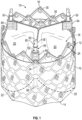
- FIG. 1 shows an exemplary prosthetic valve 10, according to one embodiment.
- the prosthetic valve 10 can include an annular stent or frame 12 having an inflow end 14 and an outflow end 16.
- the prosthetic valve 10 can also include a valvular structure 18 which is coupled to and supported inside of the frame 12.
- the valvular structure 18 is configured to regulate the flow of blood through the prosthetic valve 10 from the inflow end 14 to the outflow end 16.
- the valvular structure 18 can include, for example, a leaflet assembly comprising one or more leaflets 20 made of a flexible material.
- the leaflets 20 can be made from in whole or part, biological material, bio-compatible synthetic materials, or other such materials. Suitable biological material can include, for example, bovine pericardium (or pericardium from other sources).
- the leaflets 20 can be secured to one another at their adjacent sides to form commissures, each of which can be secured to a respective actuator 50 or the frame 102.
- the valvular structure 18 comprises three leaflets 20, which can be arranged to collapse in a tricuspid arrangement.
- Each leaflet 20 can have an inflow edge portion 22.
- the inflow edge portions 22 of the leaflets 20 can define an undulating, curved scallop shape that follows or tracks a plurality of interconnected strut segments of the frame 12 in a circumferential direction when the frame 12 is in the radially expanded configuration.
- the inflow edges of the leaflets can be referred to as a "scallop line.”
- the inflow edge portions 22 of the leaflets 20 can be sutured to adjacent struts of the frame generally along the scallop line. In other embodiments, the inflow edge portions 22 of the leaflets 20 can be sutured to an inner skirt, which in turn in sutured to adjacent struts of the frame.
- stresses on the leaflets 20 are reduced, which in turn improves durability of the valve 10.
- folds and ripples at the belly of each leaflet 20 (the central region of each leaflet), which can cause early calcification in those areas, can be eliminated or at least minimized.
- the scallop geometry also reduces the amount of tissue material used to form valvular structure 18, thereby allowing a smaller, more even crimped profile at the inflow end 14 of the valve 10.
- transcatheter prosthetic heart valves including the manner in which the valvular structure can be mounted to the frame of the prosthetic valve can be found, for example, in U.S. Patent Nos. 6,730,118 , 7,393,360 , 7,510,575 , 7,993,394 , and 8,252,202 , U.S. Publication No. 2018/0325665 and U.S. Patent Application No. 16/941,776, filed July 29, 2020 , all of which are incorporated herein by reference in their entireties.
- the prosthetic valve 10 can be radially compressible and expandable between a radially compressed configuration and a radially expanded configuration.
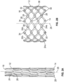
- FIGS. 2A-2B show the bare frame 12 of the prosthetic valve 10 (without the leaflets and other components) for purposes of illustrating expansion of the prosthetic valve 10 from the radially compressed configuration ( FIG. 2A ) to the radially expanded configuration ( FIG. 2B ).
- the frame 12 can include a plurality of interconnected lattice struts 24 arranged in a lattice-type pattern and forming a plurality of apices 34 at the outflow end 16 of the prosthetic valve 10.
- the struts 24 can also form similar apices 32 at the inflow end 14 of the prosthetic valve 10.
- FIG. 2B the struts 24 are shown as positioned diagonally, or offset at an angle relative to, and radially offset from, a longitudinal axis 26 of the prosthetic valve 10 when the prosthetic valve 10 is in the expanded configuration.
- the struts 24 can be offset by a different amount than depicted in FIG. 2B , or some or all of the struts 24 can be positioned parallel to the longitudinal axis 26 of the prosthetic valve 10.
- the struts 24 can comprise a set of inner struts 24a (extending from the lower left to the upper right of the frame in FIG. 2B ) and a set of outer struts 24b (extending from the upper left to the lower right of the frame in FIG. 2B ) connected to the inner struts 24a.
- the open lattice structure of the frame 12 can define a plurality of open frame cells 36 between the struts 24.
- the struts 24 can be pivotably coupled to one another at one or more pivot joints or pivot junctions 28 along the length of each strut.
- each of the struts 24 can be formed with apertures 30 at opposing ends of the strut and apertures spaced along the length of the strut.
- Respective hinges can be formed at the locations where struts 24 overlap each other via fasteners 38 ( FIG. 1 ), such as rivets or pins that extend through the apertures 30.
- the hinges can allow the struts 24 to pivot relative to one another as the frame 12 is radially expanded or compressed, such as during assembly, preparation, or implantation of the prosthetic valve 10.
- the frame struts and the components used to form the pivot joints of the frame 12 can be made of any of various suitable materials, such as stainless steel, a cobalt chromium alloy, or a nickel titanium alloy ("NiTi"), for example Nitinol.
- the frame 12 can be constructed by forming individual components (e.g., the struts and fasteners of the frame) and then mechanically assembling and connecting the individual components together. Further details regarding the construction of the frame and the prosthetic valve are described in U.S. Patent Nos. 10,603,165 and 10,806,573 , U.S. Publication Nos. 2018/0344456 and 2020/0188099 , all of which are incorporated herein by reference.
- the prosthetic valve 10 can be mechanically expanded from the radially contracted configuration to the radially expanded configuration.
- the prosthetic valve 10 can be radially expanded by maintaining the inflow end 14 of the frame 12 at a fixed position while applying a force in the axial direction against the outflow end 16 toward the inflow end 14.
- the prosthetic valve 10 can be expanded by applying an axial force against the inflow end 14 while maintaining the outflow end 16 at a fixed position, or by applying opposing axial forces to the inflow and outflow ends 14, 16, respectively.
- the prosthetic valve 10 can include one or more actuators 50 mounted to and equally spaced around the inner surface of the frame 12.
- Each of the actuators 50 can be configured to form a releasable connection with one or more respective actuators of a delivery apparatus.
- each of the actuators 50 can comprise a screw or threaded rod 52, a first anchor in the form of a cylinder or sleeve 54, and a second anchor in the form of a threaded nut 56.
- the rod 52 extends through the sleeve 54 and the nut 56.
- the sleeve 54 can be secured to the frame 12, such as with a fastener 38 that forms a hinge at the junction between two struts.
- Each actuator 50 is configured to increase the distance between the attachment locations of a respective sleeve 54 and nut 56, which causes the frame 12 to elongate axially and compress radially, and to decrease the distance between the attachment locations of a respective sleeve 54 and nut 56, which causes the frame 12 to foreshorten axially and expand radially.
- each rod 52 can have external threads that engage internal threads of the nut 56 such that rotation of the rod causes corresponding axial movement of the nut 56 toward or away from the sleeve 54 (depending on the direction of rotation of the rod 52). This causes the hinges supporting the sleeve 54 and the nut 56 to move closer towards each other to radially expand the frame or to move farther away from each other to radially compress the frame, depending on the direction of rotation of the rod 52.
- the actuators 50 can be reciprocating type actuators configured to apply axial directed forces to the frame to produce radial expansion and compression of the frame.
- the rod 52 of each actuator can be fixed axially relative to the sleeve 56 and slidable relative to the sleeve 54.
- moving the rod 52 distally relative to the sleeve 54 and/or moving the sleeve 54 proximally relative to the rod 52 radially compresses the frame.
- moving the rod 52 proximally relative to the sleeve 54 and/or moving the sleeve 54 distally relative to the rod 52 radially expands the frame.
- the prosthetic valve can also include one or more locking mechanisms that retain the frame in the expanded state.
- the locking mechanisms can be separate components that are mounted on the frame apart from the actuators, or they can be a sub-component of the actuators themselves.
- Each rod 52 can include an attachment member 58 along a proximal end portion of the rod 52 configured to form a releasable connection with a corresponding actuator of a delivery apparatus.
- the actuator(s) of the delivery apparatus can apply forces to the rods for radially compressing or expanding the prosthetic valve 10.
- the attachment member 58 in the illustrated configuration comprises a notch 60 and a projection 62 that can engage a corresponding projection of an actuator of the delivery apparatus.
- the prosthetic valve 10 includes three such actuators 50, although a greater or fewer number of actuators could be used in other embodiments.
- the leaflets 20 can have commissure attachments members 64 that wrap around the sleeves 54 of the actuators 50.
- Further details of the actuators, locking mechanisms and delivery apparatuses for actuating the actuators can be found in U.S. Patent No. 10,603,165 and U.S. Publication Nos. 2019/0060057 , and 2018/0325665 , each of which is incorporated herein by reference in its entirety. Any of the actuators and locking mechanisms disclosed in the previously filed applications can be incorporated in any of the prosthetic valves disclosed herein. Further, any of the delivery apparatuses disclosed in the previously filed applications can be used to deliver and implant any of the prosthetic valves discloses herein.
- the prosthetic valve 10 can include one or more skirts or sealing members.
- the prosthetic valve 10 can include an inner skirt (not shown) mounted on the inner surface of the frame.
- the inner skirt can function as a sealing member to prevent or decrease perivalvular leakage, to anchor the leaflets to the frame, and/or to protect the leaflets against damage caused by contact with the frame during crimping and during working cycles of the prosthetic valve.
- the prosthetic valve 10 can also include an outer skirt 70 mounted on the outer surface of the frame 12.
- the outer skirt 70 can function as a sealing member for the prosthetic valve by sealing against the tissue of the native valve annulus and helping to reduce paravalvular leakage past the prosthetic valve.
- the inner and outer skirts can be formed from any of various suitable biocompatible materials, including any of various synthetic materials, including fabrics (e.g., polyethylene terephthalate fabric) or natural tissue (e.g., pericardial tissue). Further details regarding the use of skirts or sealing members in prosthetic valve can be found, for example, in U.S. Patent No. 10,806,573 , which is incorporated herein by reference in its entirety.
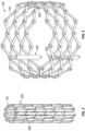
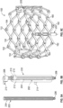
- FIGS. 3-4 show another embodiment of a prosthetic valve 100 comprising a frame 104 and expansion and locking mechanisms 200 (also referred to as "actuators").
- the prosthetic valve 100 can include leaflets 20 and other soft components, such as one or more skirts 70, which are removed for purposes of illustration.
- Expansion and locking mechanism 200 can be used to both radially expand and lock the prosthetic valve in a radially expanded state.
- three expansion and locking mechanisms 200 are attached to the frame 104 but in other example delivery assemblies, any number of expansion and locking mechanisms 200 can be used.
- FIG. 3 shows the expansion and locking mechanisms 200 attached to the frame 104 when the frame is in a radially collapsed configuration
- FIG. 4 shows expansion and locking mechanisms attached to the frame when the frame is in a radially expanded configuration.
- prosthetic valve 100 can, in certain embodiments, use other mechanisms for expansion and locking, such as linear actuators, alternate locking mechanisms, and alternate expansion and locking mechanisms. Further details regarding the use of linear actuators, locking mechanisms, and expansion and locking mechanisms in prosthetic valve can be found, for example, in U.S. Patent No. 10,603,165 .
- the expansion and locking mechanism 200 in the illustrated embodiment can include an actuator screw 202 (which functions as a linear actuator or a push-pull member in the illustrated embodiment) comprising a relatively long upper, or distal, portion 204 and a relatively shorter lower, or proximal, portion 206 at the proximal end of the screw 200, wherein the lower portion has a smaller diameter than the upper portion.
- Both the upper and lower portions 204, 206 of the screw 202 can have externally threaded surfaces.
- the actuator screw 200 can have a distal attachment piece 208 attached to its distal end having a radially extending distal valve connector 210.
- the distal attachment piece 208 can be fixed to the screw 202 (e.g., welded together or manufactured as one piece).
- the distal valve connector 210 can extend through an opening at or near the distal end of the frame 104 formed at a location on the frame where two or more struts intersect as shown in FIG. 5C .
- the distal valve connector 210 can be fixed to the frame 104 (e.g., welded). Due to the shape of the struts, the distal end of the frame 104 comprises an alternating series of distal junctions 150 and distal apices 152.
- the distal valve connectors 210 of the three expansion and locking mechanisms 200 are connected to the frame 104 through distal junctions 150.
- one or more distal valve connectors 210 can be connected to the frame 104 through distal apices 152.
- the distal valve connectors 210 can be connected to junctions closer to the proximal end of the frame 104.
- the expansion and locking mechanism 200 can further include a sleeve 212.
- the sleeve 212 can be positioned annularly around the distal portion 204 of the screw 202 and can contain axial openings at its proximal and distal ends through which the screw 202 can extend.
- the axial openings and the lumen in the sleeve 212 can have a diameter larger than the diameter of the distal portion 204 of the screw 202 such that the screw can move freely within the sleeve (the screw 202 can be moved proximally and distally relative to the sleeve 212). Because the actuator screw 202 can move freely within the sleeve, it can be used to radially expand and/or contract the frame 104 as disclosed in further detail below.
- the sleeve 212 can have a proximal valve connector 214 extending radially from its outer surface.
- the proximal valve connector 214 can be fixed to the sleeve 212 (e.g., welded).
- the proximal valve connector 214 can be axially spaced from the distal valve connector 210 such that the proximal valve connector can extend through an opening at or near the proximal end of the frame 104.
- the proximal end of the frame 104 comprises an alternating series of proximal junctions 160 and proximal apices 162.
- the proximal valve connectors 214 of the three expansion and locking mechanisms 200 are connected to the frame 104 through proximal junctions 160.
- one or more proximal valve connectors 214 can be connected to the frame 104 through proximal apices 162. In other embodiments, the proximal valve connectors 214 can be connected to junctions closer to the distal end of the frame 104.
- distal and proximal connectors 210, 214 need not be connected to opposite ends of the frame.
- the actuator 200 can be used to expand and compress the frame as long as the distal and proximal connectors are connected to respective junctions on the frame that are axially spaced from each other.
- a locking nut 216 can be positioned inside of the sleeve 212 and can have an internally threaded surface that can engage the externally threaded surface of the actuator screw 202.
- the locking nut 216 can have a notched portion 218 at its proximal end, the purpose of which is described below.
- the locking nut can be used to lock the frame 104 into a particularly radially expanded state, as discussed below.
- FIGS. 6 and 7 shows the expansion and locking mechanism 200 including components of a delivery apparatus not shown in FIGS. 5A-5C .
- the expansion and locking mechanism 200 can be releasably coupled to a support tube 220, an actuator member 222, and a locking tool 224.
- the proximal end of the support tube 220 can be connected to a handle or other control device (not shown) that a doctor or operator of the delivery assembly utilizes to operate the expansion and locking mechanism 200 as described herein.
- the proximal ends of the actuator member 222 and the locking tool 224 can be connected to the handle.
- the support tube 220 annularly surrounds a proximal portion of the locking tool 224 such that the locking tool extends through a lumen of the support tube.
- the support tube 220 and the sleeve are sized such that the distal end of the support tube abuts or engages the proximal end of the sleeve 212 such that the support tube is prevented from moving distally beyond the sleeve.
- the actuator member 222 extends through a lumen of the locking tool 224.
- the actuator member 222 can be, for example, a shaft, a rod, a cable, or wire.
- the distal end portion of the actuator member 222 can be releasably connected to the proximal end portion 206 of the actuator screw 202.
- the distal end portion of the actuator member 222 can have an internally threaded surface that can engage the external threads of the proximal end portion 206 of the actuator screw 202.
- the actuator member 222 can have external threads that engage an internally threaded portion of the screw 202.
- the distal portion of the locking tool 224 annularly surrounds the actuator screw 202 and extends through a lumen of the sleeve 212 and the proximal portion of the locking tool annularly surrounds the actuator member 222 and extends through a lumen of the support tube 220 to the handle of the delivery device.
- the locking tool 224 can have an internally threaded surface that can engage the externally threaded surface of the locking screw 202 such that clockwise or counter-clockwise rotation of the locking tool 224 causes the locking tool to advance distally or proximally along the screw, respectively.
- the distal end of the locking tool 224 can comprise a notched portion 226, as can best be seen in FIG. 6 .
- the notched portion 226 of the locking tool 224 can have an engagement surface 227 that is configured to engage a correspondingly shaped engagement surface 219 of the notched portion 218 of the locking nut 216 such that rotation of the locking tool (e.g., clockwise rotation) causes the nut 216 to rotate in the same direction (e.g., clockwise) and advance distally along the locking screw 202.
- the notched portions 218, 226 in the illustrated embodiment are configured such that rotation of the locking tool 224 in the opposite direction (e.g., counter-clockwise) allows the notched portion 226 of the tool 224 to disengage the notched portion 218 of the locking nut 216; that is, rotation of the locking tool in a direction that causes the locking tool to move proximally does not cause corresponding rotation of the nut.
- the distal end portion of the locking tool 224 can have various other configurations adapted to engage the nut 216 and produce rotation of the nut upon rotation of the locking tool for moving the nut distally, such as any of the tool configurations described herein.
- the distal end portion of the locking tool 224 can be adapted to produce rotation of the nut 216 in both directions so as move the nut distally and proximally along the locking screw 202.
- the actuator member 222 is screwed onto the proximal end portion 206 of the actuator screw 202 and the locking nut 216 is rotated such that it is positioned at the proximal end of the screw.
- the frame 104 can then be placed in a radially collapsed state and the delivery assembly can be inserted into a patient. Once the prosthetic valve is at a desired implantation site, the frame 104 can be radially expanded as described herein.
- the support tube 220 is held firmly against the sleeve 212.
- the actuator member 222 is then pulled in a proximal direction through the support tube, such as by pulling on the proximal end of the actuator member or actuating a control knob on the handle that produces proximal movement of the actuator member. Because the support tube 220 is being held against the sleeve 212, which is connected to a proximal end of the frame 104 by the proximal valve connector 214, the proximal end of the frame is prevented from moving relative to the support tube.
- movement of the actuator member 222 in a proximal direction causes movement of the actuator screw 202 in a proximal direction (because the actuator member is threaded onto the screw), thereby causing the frame 104 to foreshorten axially and expand radially.
- the frame 104 can be expanded by moving the support tube 220 distally while holding the actuator member 222 stationary or moving the support tube distally while moving the actuator member 222 proximally.
- the frame can be locked at this radially expanded size as described herein. Locking the frame can be achieved by rotating the locking tool 224 in a clockwise direction causing the notched portion 226 of the locking tool to engage the notched portion 218 of the locking nut 216, thereby advancing the locking nut distally along the actuator screw 202.
- the locking tool 224 can be so rotated until the locking nut 216 abuts an internal shoulder at the distal end of the sleeve 212 and the locking nut 216 cannot advance distally any further (see FIG. 6 ).
- the locking tool 224 can be rotated in a direction to move the locking tool proximally (e.g., in a counter-clockwise direction) to decouple the notched portion 226 from the notched portion 218 of the locking nut 216 and to unscrew the locking tool from the actuator screw 204.
- the actuator member 222 can be rotated in a direction to unscrew the actuator member from the lower portion 206 of the actuator screw 202 (e.g., the actuator member 222 can be configured to disengage from the actuator screw when rotated counter-clockwise).
- the locking tool 224 and the actuator member 222 are unscrewed from the actuator screw 204, they can be removed from the patient along with the support tube 220, leaving the actuator screw and the sleeve 212 connected to the frame 104, as shown in FIG. 5C , with the frame 104 locked in a particular radially-expanded state.
- the locking tool 224 can be formed without internal threads that engage the external threads of the actuator screw 202, which can allow the locking tool 224 to be slid distally and proximally through the sleeve 212 and along the actuator screw 202 to engage and disengage the nut 216.
- expansion and locking mechanisms can be used instead of the design previously described. Details on expansion and locking mechanisms can be found, for example, in U.S. Patent No. 10,603,165 .
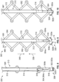
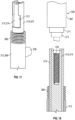
- FIGS. 8-10 illustrate an exemplary embodiment of a prosthetic heart valve 300 comprising a frame 302 and one or more expansion and locking mechanisms 310.
- the described embodiments refer to a mechanically expandable prosthetic valve having pivotably coupled struts, the expansion and locking mechanisms described herein can also be used with other mechanically expandable prosthetic valves, such as those described in U.S. Provisional Application No. 63/085,947 , which is incorporated herein by reference in its entirety.
- the frame 302 comprises a plurality of pivotably connected struts 304 defining an inflow end 306 (which is the distal end of the frame in the delivery configuration for the illustrated embodiment) and an outflow end 308 (which is the proximal end of the frame in the delivery configuration for the illustrated embodiment).
- the struts 304 are pivotably connected to each other at a plurality of junctions that permit pivoting of the struts relative to each other when the frame 302 is radially compressed and expanded, as described above in connection with prosthetic valves 10 and 100.
- the prosthetic valve 300 can include a valvular structure (e.g., valvular structure 18) and inner and/or outer skirts, as previously described, although these components are omitted for purposes of illustration. While only a portion of the frame 302 is depicted in FIGS. 8-10 , it should be appreciated that frame 302 forms an annular structure similar to frame 12 of prosthetic valve 10.
- the one or more expansion and locking mechanisms 310 can be used in lieu of or in addition to actuators 50 described above, and can comprise a first or outer member 312, a second or inner member 314, and a third or locking member 316.
- the expansion and locking mechanisms 310 can be used to radially expand the frame 302 and to lock the frame in a radially expanded state, as described in more detail below.
- the frame 302 can comprise a plurality of inflow junctions or apices 318 at the inflow end portion 306 and a plurality of outflow junctions or apices 320 at the outflow end portion 308.
- Selected inflow apices 318 can comprise one or more flanges 322 configured to engage the locking member 316 of the expansion and locking mechanism 310 to lock the prosthetic valve 300 in the radially expanded configuration.
- the expansion and locking mechanisms 310 can be circumferentially aligned with the selected inflow apices 318 comprising flanges 322.
- FIGS. 8-10 illustrate a selected inflow apex 322 comprising a first, radially inner strut 304a and a second, radially outer strut 304b.
- First strut 304a can include first flange 322a and second strut 304b can include second flange 322b.
- first and second struts 304a, 304b pivot relative to one another to define a gap G between them, as shown in FIG. 9 .
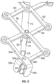
- Each flange 322a, 322b can comprise a respective axial portion 324a, 324b that extends axially past the junction of the first and second struts 304a, 304b, and a respective radial portion 326a, 326b ( FIG. 15 ) that extends radially inward toward a longitudinal axis of the prosthetic valve 300.
- the expansion and locking mechanisms 310 can be mounted on the outside of the frame 312 and the radial portions 326a, 326b can extend radially outward from the frame.
- the first axial portion 324a can have a length L 1 and the second axial portion 324b can have a length L 2 .
- the length L 2 can be greater than the length Li, or vice versa, such that when the frame 302 is in the radially compressed configuration (see e.g., FIGS. 14-15 ) the radial portions 326a, 326b can be circumferentially aligned with one another (meaning that their respective circumferential positions are aligned along a line that is parallel to a longitudinal axis of the frame).
- the differing lengths L 1 and L 2 of the axial portions 324a, 324b allow the flanges 322a, 322b to pivot relative to one another about inflow apex 318 without the radial portions 326a, 326b contacting or abutting one another.
- the first radial portion 326a can have a length L 3 and the second radial portion 326b can have a length L 4 .
- Length L 4 can be greater than length L 3 such that when the radial portions 326a, 326b are circumferentially aligned with one another both radial portions terminate at substantially the same radial location. In other words, neither radial portion extends past the other.
- the length L 3 can be greater than the length L 4 .
- FIGS. 8-10 show only a single expansion and locking mechanism 310 mounted to the frame 302, it should be appreciated that the prosthetic valve 300 can comprise any number of expansion and locking mechanisms 310.
- a prosthetic valve can comprise two expansion and locking mechanisms, or three expansion and locking mechanisms, or four expansion and locking mechanisms, etc.
- the expansion and locking mechanisms 310 can be placed at any position about the circumference of the frame 302.
- the expansion and locking mechanisms 310 can be equally spaced from one another about the circumference of the frame 302.
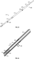
- each expansion and locking mechanism 310 can include a first, or outer member 312, a second or inner member 314, and a locking member 316.
- the outer member 312 can comprise a first lumen or bore 328 ( FIG. 12 ) sized to receive at least a portion of the inner member 314, and the inner member 314 can comprise a second lumen or bore 330 ( FIG. 12 ) sized to receive at least a portion of the locking member 316.
- the outer member 312, inner member 314, and locking member 316 can each move axially relative to one another.
- a distal end portion 332 of the inner member 314 can be coupled to the frame 302 at a first location via a fastener 334 that is affixed to and extends radially from the distal end portion 332 of the inner member 314.
- the fastener can be, for example, a rivet or a pin.
- the fastener 334 can extend through corresponding apertures at a junction of two overlapping struts 304 of frame 302 and can serve as a pivot pin around which the two struts 304 can pivot relative to one another and the inner member 314.
- an end cap or nut can be disposed over an end portion of the fastener 334 to retain the fastener within the corresponding apertures.
- the outer member 312 can be coupled to the frame 302 at a second location, axially spaced from the first location.
- the inner member 314 is secured to the frame 302 near the distal or inflow end 306 of the frame and the outer member 312 is secured to the frame 302 closer to or at the proximal or outflow end 308 of the frame, such as via a fastener 336 ( FIG. 11 ), which can be, for example, a rivet or a pin.
- the fastener 336 is affixed to and extends radially from the outer member 312 through corresponding apertures at a junction of two overlapping struts 304 and can serve as a pivot pin around which the two struts 304 can pivot relative to each other and the outer member 312.
- a nut can be mounted on each fastener 336 to retain the fastener within the corresponding apertures.
- the expansion and locking mechanism 310 can be coupled to the frame 302 at any two axially spaced, circumferentially aligned locations on the frame.
- the inner member and/or outer member 314, 312 need not comprise fasteners 334, 336 and can be coupled to the frame 302 via other means of attachment such as welding, adhesives, etc.
- the inner member 314 can be axially movable relative to the outer member 312 in a proximal direction, as shown by arrow 338, and in a distal direction, as shown by arrow 340.
- arrow 338 a proximal direction
- distal direction a distal direction
- arrow 340 a distal direction
- moving the inner member 314 proximally toward the outflow end 308 of the frame, as shown by arrow 338, while holding the outer member 312 in a fixed position and/or moving the outer member 312 distally toward the inflow end 306 of the frame can cause the frame 302 to foreshorten axially and expand radially.
- moving the inner member 314 distally in the direction of arrow 338 and/or moving the outer member 312 proximally causes the frame 302 to elongate axially and compress radially.
- outer member 312 can further comprise a recess 342.
- the recess 342 can extend through a thickness of the outer member 312 and can extend to the distal edge 344 of the outer member.
- the recess 342 can be configured to limit the proximal advancement of the inner member 314 within the outer member 312.
- the inner member 314 can slide relative to the outer member 312 such that the fastener 334 of the inner member 314 can slide within the recess 342.
- the inner member 314 can continue moving relative to the outer member 312 until the fastener 334 abuts a proximal edge 346 of the recess 342, restraining further motion of the inner member 314 relative to the outer member 312.
- the locking member 316 can have a first end portion 348 and a second end portion 350.
- the first end portion 348 can have a circular shape in cross-section and can extend at least partially into the second bore 330 of the inner member 314.
- the second end portion 350 can comprise an engagement member 352 configured to engage one or more portions of the frame 302 to lock the frame 302 in the expanded configuration and prevent compression of the frame, as described in more detail below.
- the engagement member 352 is configured as a wedge having a base portion 354 and an apical portion 356.
- the base portion 354 can have a first width Wi that tapers to a second width W 2 at the apical portion 356.
- the base portion 354 can comprise a shoulder 358 sized to abut a distal edge 360 of the second member 314, thereby preventing movement of the locking member 316 relative to the second member 314 past a predetermined point.
- the engagement member 352 can have a first side wall 362 and a second side wall 364 inclined relative to one another at an angle ⁇ , also referred to as the "wedge angle.”
- the wedge angle ⁇ can be selected according to the following Equation 1.
- the wedge angle can be configured to correspond with a selected prosthetic valve diameter.
- tan ⁇ ⁇ ; where ⁇ is the wedge angle, and ⁇ is the coefficient of friction between the engagement member 352 and the flanges 322 of the frame 302.
- the wedge angle ⁇ can be between about 0 degrees and about 10 degrees.
- the wedge angle ⁇ can be between about 4 degrees and about 6 degrees.
- the wedge angle ⁇ can be determined using the coefficient of friction between metals.
- the static coefficient of wet friction for metals can be between about 0.1 to about 0.3. If the tangent of the wedge angle is less than the coefficient of friction, the locking member 316 will remain in the locked position under the radial forces applied by the native aortic annulus.
- the outer member 312, inner member 314, and locking member 316 can each have a substantially cylindrical configuration.
- This configuration can advantageously simplify manufacturing, for example, by allowing much simpler processing and machining procedures (such as Swiss-type and milling procedures) to be used.
- the telescoping movement of the members 312, 314, 316 relative to one another advantageously provides continuous valve expansion wherein the expansion and locking mechanism 310 can be easily maneuvered between the locked and unlocked configurations.
- the proximal end portion of each member 312, 314, 316 can comprise an engagement portion configured to releasably couple a corresponding actuator of a delivery apparatus, as described in more detail below.
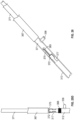
- the proximal end portion 366 of the outer member 312 comprises an outer engagement portion configured as a threaded portion 368
- the proximal end portion 370 of the second member 314 comprises an engagement portion 372 including one or more cutouts
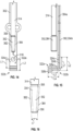
- a proximal end portion 374 of the locking member 316 can comprise an engagement portion configured as an inner bore including, for example, a threaded portion 376 ( FIG. 18 ).
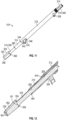
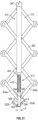
- the expansion and locking mechanism 310 can be releasably coupled to a delivery apparatus, such as delivery apparatus 500 ( FIG. 22 ) comprising one or more actuator assemblies 508.
- a delivery apparatus such as delivery apparatus 500 ( FIG. 22 ) comprising one or more actuator assemblies 508.
- an actuator assembly 508 can couple a respective expansion and locking mechanism 310 in the following exemplary manner.
- the outer threaded portion 368 ( FIG. 25A ) of the outer member 312 can be configured to couple a correspondingly threaded portion 369 of a first actuator 367 of the delivery apparatus.
- a proximal end portion 370 ( FIG. 17 ) of the second member 314 can comprise an engagement portion 372 including one or more cutouts and configured to releasably couple a second actuator 371 extending coaxially through the first actuator 367.
- the second actuator 371 can comprise one or more flexible elongated elements 375 including protrusions 377 configured to releasably couple the engagement portion 372 of the second member 314.
- the elongated elements 375 can be disposed, for example, at the distal end of the second actuator 371.
- the elongated elements can be formed by, for example, laser cutting, and the protrusions 377 can have a shape corresponding to the shape of the cutouts.
- the elongated elements 375 can be configured to bias radially outward, for example, by shape setting the elongated elements 375.
- the second actuator 371 can comprise a cutout 365 configured to allow the elongated elements 375 to flex outward.
- the second actuator 371 can be positioned such that the protrusions 377 are disposed adjacent the cutouts of the engagement portion 372, as shown in FIG. 25C .
- the first actuator 367 is advanced (e.g., distally) over the second actuator to couple the outer member 312, the elongated elements 375 are radially compressed until they sit within the cutouts, as shown in FIG.
- the first actuator 367 can continue to be advanced until the threaded portion 369 of the first actuator 367 engages the threaded portion 368 of the outer member 312, as shown in FIG. 26 .
- a proximal end portion 374 of the locking member 316 can comprise an engagement portion configured as an inner bore including a threaded portion 376.
- a third actuator 373 of the delivery apparatus can extend coaxially through the first and second actuators 367, 371 and can have a correspondingly threaded portion 379 configured to releasably couple the threaded portion 376 of the locking member 316.
- the first, second, and third actuators 367, 371 and 373 can form an actuator assembly 508.
- Each actuator assembly 508 can be releasably coupled to and control operation of a respective expansion and locking mechanism 310.
- Each actuator assembly 508 can be coupled to a handle 504 of the delivery apparatus and the components of the actuator assembly (e.g., actuators 367, 371, 373) can be axially movable relative to one another to cause corresponding axial movement of the first, second, and locking members 312, 314, 316 relative to one another, as further described below.
- the engagement portions can have other configurations that permit the first, second, and locking members 312, 314, 316 to be releasably coupled to the delivery apparatus.
- the engagement portion of the locking member 316 can comprise a magnetic material and the third actuator can comprise a corresponding magnet that can extend into the engagement portion.
- a prosthetic valve 300 including one or more expansion and locking mechanisms 310 can be expanded in the following exemplary manner.
- the prosthetic valve 300 is placed in a radially compressed state and releasably coupled to a distal end portion of a delivery apparatus (such as delivery apparatus 500 shown in FIG. 22 ), as described above, and advanced through the vasculature of a patient to a selected implantation site (e.g., the native aortic annulus).
- the prosthetic valve 300 can then be deployed at the implantation site and can be expanded and locked in the expanded configuration using the expansion and locking mechanisms 310.
- the delivery apparatus can be uncoupled from the expansion and locking mechanisms 310 and removed from the patient's body.
- the physician can actuate the delivery apparatus, which can actuate the one or more expansion and locking mechanisms 310.
- the second member 314 can move proximally (as shown by arrow 338) and/or the first member 312 can move distally (as shown by arrow 340) to decrease the distance between the attachment locations, causing the frame 302 to foreshorten axially and expand radially until a selected diameter is achieved.
- the radially inner and radially outer struts 304a, 304b can pivot relative to one another, thereby pivoting the first and second flanges 322a, 322b relative to one another to define the gap G between them (see FIG. 9 ).
- the physician can use the delivery apparatus to advance the locking member 316 distally until the engagement member 352 is disposed within the gap G between the first and second flanges 322a, 322b, as shown in FIG. 10 .
- the engagement of the engagement member 352 with the first and second flanges 322a, 322b retains the frame 302 in a locked configuration, where the frame can be further radially expanded but cannot be radially collapsed.
- the engagement of the engagement member 352, with the flanges 322 permits pivoting movement of the struts 304 relative to each other in a first direction to expand the frame 302 and resists pivoting movement of the struts 304 relative to each other to resist radial compression of the frame 302 from forces exerted on the frame by the surrounding anatomy.
- the frictional engagement between the engagement member 352 and the flanges 322 prevents the engagement member 352 from being displaced relative to the flanges 322.
- the patient's native anatomy e.g., the native aortic annulus
- the frictional engagement of the engagement member 352 with the flanges 322 prevents such forces from displacing the engagement member and compressing the frame 302.
- the prosthetic valve can be unlocked by retracting the locking member 316 proximally until the engagement member 352 is no longer disposed between the first and second flanges 322a, 322b, allowing the struts 304 to pivot freely relative to one another in either direction.
- a proximally-directed force must be applied to the locking member 316 that is greater than the force of the frictional engagement between the flanges 322 and the engagement member 352.
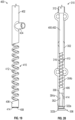
- the expansion and locking mechanism 310 can comprise second member 400.
- Second member 400 can be similar to second member 314 except that second member 400 can be configured to bias the locking member 316 in a distal direction, as described in more detail below.
- the second member 400 can have a first end portion 402 including a fastener 404 similar to fastener 332 described above, a second end portion 406, and an inner lumen or bore 408.
- the second member 400 can comprise a biasing portion 410 disposed between the first and second end portions 402, 406.
- the biasing portion 410 can be movable between a compressed configuration and an extended configuration and can be configured to bias the second end portion 406 in a first direction, for example, toward the inflow end portion 306 of the prosthetic valve 300.
- the biasing portion 410 is configured as a spring 412 (such as a compression spring).
- the spring 412 can be formed integrally with the second member 400, for example, by laser cutting a central portion of the second member 400 into a helical shape.
- the spring 412 can be formed as a separate component and can be coupled to the first and second end portions 402, 406 of the second member 400.
- the biasing portion 410 can have any of various configurations.
- the biasing portion 410 can comprise a spring washer, a compressible polymeric sleeve, etc.
- the locking member 316 extends at least partially through the second member 400.
- the biasing portion 410 can be sized such that when the prosthetic valve 300 is in the compressed configuration, the biasing portion 410 is axially compressed or loaded. In the loaded state, a distal edge 414 of the second member 400 applies a proximally-directed force to the shoulder 358 of the locking member 316.
- the biasing portion 410 biases the locking member 316 distally toward the inflow end 306 such that the engagement member 352 abuts the radially extending portion 326a of the first flange 322a.
- the inner and outer struts 304a, 304b pivot relative to one another, thereby pivoting the flanges 322 relative to one another to define the gap G between them.
- the biasing portion 410 continues to bias the locking member 316, and therefore the engagement portion 352, distally against the first and/or second flanges 322a, 322b until the gap G is large enough to accommodate the engagement member 352, at which point the biasing portion 410 will bias the engagement member 352 into the gap G, as shown in FIG. 21 .
- the frictional engagement between the engagement member 352 and the flanges 322 prevents the engagement member 352 from being displaced relative to the flanges 322.
- the patient's native anatomy e.g., the native aortic annulus
- the frictional engagement of the engagement member 352 with the flanges 322 prevents such forces from displacing the engagement member and compressing the frame 302.
- the prosthetic valve can be unlocked by retracting the locking member 316 proximally until the engagement member 352 is no longer disposed between the first and second flanges 322a, 322b, thereby allowing the struts 304 to pivot freely relative to one another in either direction.
- a proximally-directed force must be applied to the locking member 316 that is greater than the force of the frictional engagement between the flanges 322 and the engagement member 352 and the force of the biasing portion 410.
- the biasing portion 410 can be sized such that when the prosthetic valve 300 is in the expanded configuration ( FIG. 21 ), the biasing portion 410 is in the uncompressed or unloaded configuration such that the biasing portion no longer applies a biasing force. In other embodiments, the biasing portion 410 can be sized such that when the prosthetic valve 300 is in the expanded configuration, the biasing portion 410 continues to apply a biasing force in the distal direction to help retain the engagement member 352 between the flanges 322.
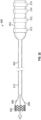
- FIG. 22 illustrates a delivery apparatus 500, according to one embodiment, adapted to deliver a prosthetic heart valve 502, such as the illustrated prosthetic heart valve 10, 100, or 300 described above.
- the prosthetic valve 502 can be releasably coupled to the delivery apparatus 500.
- the delivery apparatus 500 and other delivery apparatuses disclosed herein can be used to implant prosthetic devices other than prosthetic valves, such as stents or grafts.
- the delivery apparatus 500 in the illustrated embodiment generally includes a handle 504, a first elongated shaft 506 (which comprises an outer shaft in the illustrated embodiment) extending distally from the handle 504, at least one actuator assembly 508 extending distally through the outer shaft 506.
- the at least one actuator assembly 508 can be configured to radially expand and/or radially collapse the prosthetic valve 502 when actuated.
- each actuator 508 can be provided for each actuator (e.g., each expansion and locking mechanism) on the prosthetic valve.
- three actuator assemblies 508 can be provided for a prosthetic valve having three actuators. In other embodiments, a greater or fewer number of actuator assemblies can be present.
- a distal end portion 516 of the shaft 506 can be sized to house the prosthetic valve in its radially compressed, delivery state during delivery of the prosthetic valve through the patient's vasculature. In this manner, the distal end portion 516 functions as a delivery sheath or capsule for the prosthetic valve during delivery,
- each actuator assembly 508 can be releasably coupled to the prosthetic valve 502.
- each actuator assembly 508 can be coupled to a respective actuator (e.g., expansion and locking mechanism 310) of the prosthetic valve 502.
- Each actuator assembly 508 can comprise a first actuator (e.g., first actuator 367, which can be a support tube), a second actuator (e.g., second actuator 371), and a third actuator (e.g., third actuator 373, which can be a locking tool for operating locking member 316).
- the actuator assembly can transmit pushing and/or pulling forces to portions of the prosthetic valve to radially expand and collapse the prosthetic valve as previously described.
- the actuator assemblies 508 can be at least partially disposed radially within, and extend axially through, one or more lumens of the outer shaft 506.
- the actuator assemblies 508 can extend through a central lumen of the shaft 506 or through separate respective lumens formed in the shaft 506.
- the handle 504 of the delivery apparatus 500 can include one or more control mechanisms (e.g., knobs or other actuating mechanisms) for controlling different components of the delivery apparatus 500 in order to expand and/or deploy the prosthetic valve 10.
- control mechanisms e.g., knobs or other actuating mechanisms
- the handle 504 comprises first, second, third and fourth knobs 510, 512, 514, and 515.
- the first knob 510 can be a rotatable knob configured to produce axial movement of the outer shaft 506 relative to the prosthetic valve 502 in the distal and/or proximal directions in order to deploy the prosthetic valve from the delivery sheath 516 once the prosthetic valve has been advanced to a location at or adjacent the desired implantation location with the patient's body.
- rotation of the first knob 510 in a first direction e.g., clockwise
- rotation of the first knob 510 in a second direction e.g., counter-clockwise
- the first knob 510 can be actuated by sliding or moving the knob 510 axially, such as pulling and/or pushing the knob. In other embodiments, actuation of the first knob 510 (rotation or sliding movement of the knob 510) can produce axial movement of the actuator assemblies 508 (and therefore the prosthetic valve 502) relative to the delivery sheath 516 to advance the prosthetic valve distally from the sheath 516.
- the second knob 512 can be a rotatable knob configured to produce radial expansion and/or contraction of the prosthetic valve 502.
- rotation of the second knob 512 can move the first actuator (e.g., actuator 367) and the second actuator (e.g., actuator 371) relative to one another (for example, to cause corresponding movement of the outer and inner members 312, 314 relative to one another).
- Rotation of the second knob 512 in a first direction e.g., clockwise
- rotation of the second knob 512 in a second direction e.g., counter-clockwise
- the second knob 512 can be actuated by sliding of moving the knob 512 axially, such as pulling and/or pushing the knob.
- the first and second actuators can each be coupled to a respective knob such that they can be actuated independently from one another.
- the third knob 514 can be a rotatable knob configured to retain the prosthetic heart valve 502 in its expanded configuration.
- the third knob 514 can be operatively connected to a third actuator (e.g., third actuator 373) that can be releasably coupled to a locking member (e.g., locking member 316).
- Rotation of the third knob in a first direction can advance the third actuator distally to, for example, advance the engagement member 352 of locking member 316 such that it engages the flanges 322 to resist radial compression of the frame of the prosthetic valve, as described above.
- Rotation of the knob 514 in the opposite direction can retract the third actuator proximally to unlock the frame and allow for repositioning or recapture and removal.
- the third knob 514 can be actuated by sliding or moving the third knob 514 axially, such as pulling and/or pushing the knob.
- the handle 504 can include a fourth knob 515 (e.g., a rotatable knob) operatively connected to a proximal end portion of one or more of the actuators 367, 371, 373.
- the fourth knob 515 can be configured to, upon rotation of the knob, to decouple each of the one or more actuators from, for example, a respective component of the expansion and locking mechanism.
- the fourth knob 515 can be operable to rotate the first actuator 367 in a direction that causes a threaded distal end portion of the first actuator to decouple from the threaded portion 368 of the outer member 312 of the expansion and locking mechanism 310.
- the fourth knob 515 (or an additional knob) can be operable to rotate the third actuator 373 in a direction that causes a threaded distal end portion of the third actuator to decouple from the threaded portion 376 of the locking member 316 of the expansion and locking mechanism 310.
- the disclosed embodiments can be adapted to deliver and implant prosthetic devices in any of the native annuluses of the heart (e.g., the pulmonary, mitral, and tricuspid annuluses), and can be used with any of various delivery approaches (e.g., retrograde, antegrade, transseptal, transventricular, transatrial, etc.).
- native annuluses of the heart e.g., the pulmonary, mitral, and tricuspid annuluses
- various delivery approaches e.g., retrograde, antegrade, transseptal, transventricular, transatrial, etc.
- expansion and locking mechanisms 310 as shown in FIG. 11 or FIG. 20 can be used in combination with prosthetic valve 100 or with prosthetic valve 10.
- proximal refers to a position, direction, or portion of a device that is closer to the user and further away from the implantation site.
- distal refers to a position, direction, or portion of a device that is further away from the user and closer to the implantation site.
- proximal motion of a device is motion of the device away from the implantation site and toward the user (e.g., out of the patient's body)
- distal motion of the device is motion of the device away from the user and toward the implantation site (e.g., into the patient's body).
Landscapes
- Health & Medical Sciences (AREA)
- Cardiology (AREA)
- Engineering & Computer Science (AREA)
- Biomedical Technology (AREA)
- Heart & Thoracic Surgery (AREA)
- Transplantation (AREA)
- Oral & Maxillofacial Surgery (AREA)
- Vascular Medicine (AREA)
- Life Sciences & Earth Sciences (AREA)
- Animal Behavior & Ethology (AREA)
- General Health & Medical Sciences (AREA)
- Public Health (AREA)
- Veterinary Medicine (AREA)
- Mechanical Engineering (AREA)
- Prostheses (AREA)
Abstract
Description
- This application claims the benefit of
United States Provisional Application No. 62/961,043 filed on January 14, 2020 - The present disclosure relates to implantable, mechanically expandable prosthetic devices, such as prosthetic heart valves, and to methods and delivery assemblies for, and including, such devices.
- The human heart can suffer from various valvular diseases. These valvular diseases can result in significant malfunctioning of the heart and ultimately require repair of the native valve or replacement of the native valve with an artificial valve. There are a number of known repair devices (e.g., stents) and artificial valves, as well as a number of known methods of implanting these devices and valves in humans. Percutaneous and minimally-invasive surgical approaches are used in various procedures to deliver prosthetic medical devices to locations inside the body that are not readily accessible by surgery or where access without surgery is desirable. In one specific example, a prosthetic heart valve can be mounted in a crimped state on the distal end of a delivery apparatus and advanced through the patient's vasculature (e.g., through a femoral artery and the aorta) until the prosthetic heart valve reaches the implantation site in the heart. The prosthetic heart valve is then expanded to its functional size, for example, by inflating a balloon on which the prosthetic valve is mounted, actuating a mechanical actuator that applies an expansion force to the prosthetic heart valve, or by deploying the prosthetic heart valve from a sheath of the delivery apparatus so that the prosthetic heart valve can self-expand to its functional size.
- Prosthetic heart valves that rely on a mechanical actuator for expansion can be referred to as "mechanically expandable" prosthetic heart valves. Mechanically expandable prosthetic heart valves can provide one or more advantages over self-expandable and balloon-expandable prosthetic heart valves. For example, mechanically expandable prosthetic heart valves can be expanded to various diameters. Mechanically expandable prosthetic heart valves can also be compressed after an initial expansion (e.g., for repositioning and/or retrieval).
- Despite the recent advancements in percutaneous valve technology, there remains a need for improved transcatheter heart valves and delivery devices for such valves.
- Embodiments of improved prosthetic implant delivery assemblies and frames therefor are disclosed herein, as well as related methods and devices for such assemblies. In several embodiments, the disclosed assemblies are configured for delivering replacement heart valves into a heart of a patient.
- In a representative embodiment, an implantable prosthetic device can comprise a frame movable between a radially compressed and a radially expanded configuration, the frame comprising an inflow end portion and an outflow end portion, the frame comprising a plurality of struts, and at least one expansion and locking mechanism. The at least one expansion and locking mechanism can comprise a first member coupled to the frame at a first location, a second member coupled to the frame at a second location spaced apart from the first location, the second member extending at least partially into the first member, and a third member having a first end portion and a second end portion, the first end portion extending at least partially into the first member and the second end portion comprising an engagement portion. The plurality of struts can include a first strut and a second strut pivotably coupled to one another to form an apex, the first strut comprising a first flange and the second strut comprising a second flange. When the frame is in the expanded configuration, advancement of the third member in a distal direction positions the engagement member between the first and second flanges such that the first and second flanges engage the engagement member to resist pivoting of the first and second struts relative to one another in a first direction to resist radial compression of the frame.
- In another representative embodiment, an assembly can comprise a prosthetic heart valve and a delivery apparatus. The prosthetic heart valve can comprise a frame movable between a radially compressed and a radially expanded configuration, the frame comprising an inflow end portion and an outflow end portion, the frame comprising a first strut and a second strut comprising a first flanged portion and a second flanged portion respectively, and at least one expansion and locking mechanism. The at least one expansion and locking mechanism can comprise a first member coupled to the frame at a first location, a second member coupled to the frame at a second location spaced apart from the first location, the second member extending at least partially into the first member, and a third member comprising an engagement portion. The delivery apparatus can comprise a handle, a first actuation member extending from the handle and coupled to the first member, the first actuation member configured to apply a distally directed force to the first member, a second actuation member extending from the handle and coupled to the second member, the second actuation member configured to apply a proximally directed force to the second member, and a third actuation member extending from the handle and coupled to the third member. The prosthetic heart valve can be radially expandable from the radially compressed configuration to the radially expanded configuration upon application of at least one of the first distally directed force and the proximally directed force to the prosthetic heart valve via the first and second actuation members, respectively. When the prosthetic heart valve is in the radially expanded configuration the engagement portion of the third member selectively engages the first and second flanges to prevent compression of the frame.
- In a representative embodiment, a method can comprise inserting a distal end of a delivery apparatus into the vasculature of a patient, the delivery apparatus releasably coupled to a prosthetic heart valve movable between a radially compressed and a radially expanded configuration. The prosthetic valve can comprise a frame comprising an inflow end portion, an outflow end portion, and a plurality of struts, and an expansion and locking mechanism comprising a first member coupled to the frame at a first location, a second member coupled to the frame at a second location spaced apart from the first location, and a third member having a first end portion and a second end portion comprising an engagement portion. The method can further comprise advancing the prosthetic valve to a selected implantation site, moving at least one of the first member distally and the second member proximally to radially expand the prosthetic valve, and advancing the third member distally such that the engagement portion engages one or more flanges radially extending from respective struts of the plurality of struts to lock the prosthetic valve in an expanded configuration.
- In another representative embodiment, an implantable prosthetic device can comprise a frame movable between a radially compressed and a radially expanded configuration, the frame comprising an inflow end portion, an outflow end portion, and a plurality of struts including a first strut and a second strut pivotably coupled to one another to form an apex, the first strut comprising a first flange and the second strut comprising a second flange. The frame further can further comprise one or more expansion and locking mechanisms comprising a first member coupled to the frame at a first location, a second member coupled to the frame at a second location, the second member extending at least partially into the first member, and a third member extending at least partially into the second member and comprising an engagement portion. The second member can comprise a biasing member configured to bias the engagement portion of the third member toward the inflow end of the frame. When the frame is in the expanded configuration advancement of the third member in a distal direction via the biasing member positions the engagement member between the first and second flanges such that the first and second flanges engage the engagement member to resist pivoting of the first and second struts relative to one another in a first direction to resist radial compression of the frame.
- In still another representative embodiment, an assembly can comprise a prosthetic heart valve and a delivery apparatus. The prosthetic heart valve can comprise a frame movable between a radially compressed and a radially expanded configuration, the frame comprising an inflow end portion, an outflow end portion, and a first strut and a second strut comprising a first flanged portion and a second flanged portion respectively. The frame can further comprise an expansion and locking mechanism comprising a first member, a second member, and a third member. The first member can be coupled to the frame at a first location, the second member can be coupled to the frame at a second location spaced apart from the first location and can comprise a biasing member configured to bias an engagement portion of the third member toward the inflow end of the frame. The delivery apparatus can comprise a handle, a first actuation member extending from the handle and coupled to the first member, the first actuation member configured to apply a distally directed force to the first member, and a second actuation member extending from the handle and coupled to the second member, the second actuation member configured to apply a proximally directed force to the second member. The prosthetic heart valve is radially expandable from the radially compressed configuration to the radially expanded configuration upon application of at least one of the first distally directed force and the proximally directed force to the prosthetic heart valve via the first and second actuation members, respectively. When the prosthetic heart valve is in the expanded configuration, advancement of the third member in a distal direction via the biasing member positions the engagement member between the first and second flanged portions such that the first and second flanged portions engage the engagement member to resist pivoting of the first and second struts relative to one another in a first direction to resist radial compression of the frame
- The foregoing and other objects, features, and advantages of the disclosure will become more apparent from the following detailed description, which proceeds with reference to the accompanying figures.
-
-
FIG. 1 is a perspective view of a prosthetic heart valve, according to one embodiment. -
FIG. 2A is a side elevation view of the frame of the prosthetic heart valve ofFIG. 1 , shown in a radially compressed state. -
FIG. 2B is a side elevation view of the frame of the prosthetic heart valve ofFIG. 1 , shown in a radially expanded state. -
FIG. 3 is a perspective view of a prosthetic valve frame, shown in a radially collapsed state, having a plurality of expansion and locking mechanisms, according to another embodiment. -
FIG. 4 is a perspective view of the frame and the expansion and locking mechanisms ofFIG. 3 , with the frame shown in a radially expanded state. -
FIG. 5A is a perspective view of a screw of one of the expansion and locking mechanisms ofFIG. 3 . -
FIG. 5B is a perspective view of one of the expansion and locking mechanisms ofFIG. 3 . -
FIG. 5C is another perspective view of the frame and the expansion and locking mechanisms ofFIG. 3 , with the frame shown in a radially expanded state. -
FIG. 6 is another perspective view of one of the expansion and locking mechanisms ofFIG. 3 . -
FIG. 7 shows a cross sectional view of one of the expansion and locking mechanisms ofFIG. 3 along with a portion of the frame. -
FIG. 8 is a side elevational view of a portion of a frame for a prosthetic heart valve comprising an expansion and locking mechanism, according to one embodiment. -
FIG. 9 is a side elevational view of a portion of the frame ofFIG. 8 shown in an expanded configuration. -
FIG. 10 is a side elevational view of a portion of the frame ofFIG. 8 shown in an expanded and locked configuration. -
FIG. 11 is a perspective view of an expansion and locking mechanism ofFIG. 8 . -
FIG. 12 is a cross-sectional perspective view of a portion of the expansion and locking mechanism ofFIG. 11 . -
FIG. 13 is a perspective view of a portion of the frame ofFIG. 8 shown in an expanded and locked configuration. -
FIG. 14 is a side elevational view of a portion of the frame ofFIG. 8 shown in a compressed configuration. -
FIG. 15 is a side elevational view of a portion of the frame ofFIG. 8 shown in a compressed configuration. -
FIG. 16 is a side elevational view of a portion of the expansion and locking mechanism ofFIG. 11 . -
FIG. 17 is a perspective view of a portion of the expansion and locking mechanism ofFIG. 11 . -
FIG. 18 is a cross-sectional side elevational view of a portion of the expansion and locking mechanism ofFIG. 11 and a portion of a delivery apparatus, according to one embodiment. -
FIG. 19 is a perspective view of a portion of a second member of an expansion and locking mechanism, according to another embodiment. -
FIG. 20 is a side elevational view of a portion of a frame comprising an expansion and locking mechanism including the second member ofFIG. 19 , shown in a compressed configuration. -
FIG. 21 is a side elevational view of a portion of the frame ofFIG. 20 , shown in an expanded configuration. -
FIG. 22 is a side elevation view of a delivery apparatus for a prosthetic heart valve, according to one embodiment. -
FIG. 23 is a perspective view of the expansion and locking mechanism ofFIG. 11 coupled to a portion of an actuator assembly of a delivery apparatus, according to one embodiment. -
FIG. 24 is a cross-sectional view of a portion of the expansion and locking mechanism and actuator assembly ofFIG. 23 . -
FIGS. 25A-25D are side elevational views of the actuator assembly ofFIG. 23 in the process of coupling the expansion and locking mechanism ofFIG. 23 . -
FIG. 26 is a perspective view of the expansion and locking mechanism and actuator assembly ofFIG. 23 . - Described herein are examples of prosthetic implant delivery assemblies and components thereof which can improve a physician's ability to control the size of a mechanically-expandable prosthetic implant, such as prosthetic valves (e.g., prosthetic heart valves or venous valves), stents, or grafts, as well as facilitate separation of the prosthetic implant from the delivery assembly, during the implantation procedure. The present disclosure also provides frames for use with such prosthetic implants. The frames can comprise expansion and locking mechanisms configured to expand and/or compress the frame and to hold the frame in an expanded configuration when the implant is expanded at a selected delivery site within a patient.
- Prosthetic valves disclosed herein can be radially compressible and expandable between a radially compressed state and a radially expanded state. Thus, the prosthetic valves can be crimped on or retained by an implant delivery apparatus in the radially compressed state during delivery, and then expanded to the radially expanded state once the prosthetic valve reaches the implantation site. It is understood that the valves disclosed herein may be used with a variety of implant delivery apparatuses, and examples thereof will be discussed in more detail later.
-
FIG. 1 shows an exemplaryprosthetic valve 10, according to one embodiment. Theprosthetic valve 10 can include an annular stent orframe 12 having aninflow end 14 and anoutflow end 16. Theprosthetic valve 10 can also include avalvular structure 18 which is coupled to and supported inside of theframe 12. Thevalvular structure 18 is configured to regulate the flow of blood through theprosthetic valve 10 from theinflow end 14 to theoutflow end 16. - The
valvular structure 18 can include, for example, a leaflet assembly comprising one ormore leaflets 20 made of a flexible material. Theleaflets 20 can be made from in whole or part, biological material, bio-compatible synthetic materials, or other such materials. Suitable biological material can include, for example, bovine pericardium (or pericardium from other sources). Theleaflets 20 can be secured to one another at their adjacent sides to form commissures, each of which can be secured to arespective actuator 50 or the frame 102. - In the depicted embodiment, the
valvular structure 18 comprises threeleaflets 20, which can be arranged to collapse in a tricuspid arrangement. Eachleaflet 20 can have aninflow edge portion 22. As shown inFIG. 1 , theinflow edge portions 22 of theleaflets 20 can define an undulating, curved scallop shape that follows or tracks a plurality of interconnected strut segments of theframe 12 in a circumferential direction when theframe 12 is in the radially expanded configuration. The inflow edges of the leaflets can be referred to as a "scallop line." - In some embodiments, the
inflow edge portions 22 of theleaflets 20 can be sutured to adjacent struts of the frame generally along the scallop line. In other embodiments, theinflow edge portions 22 of theleaflets 20 can be sutured to an inner skirt, which in turn in sutured to adjacent struts of the frame. By forming theleaflets 20 with this scallop geometry, stresses on theleaflets 20 are reduced, which in turn improves durability of thevalve 10. Moreover, by virtue of the scallop shape, folds and ripples at the belly of each leaflet 20 (the central region of each leaflet), which can cause early calcification in those areas, can be eliminated or at least minimized. The scallop geometry also reduces the amount of tissue material used to formvalvular structure 18, thereby allowing a smaller, more even crimped profile at theinflow end 14 of thevalve 10. - Further details regarding transcatheter prosthetic heart valves, including the manner in which the valvular structure can be mounted to the frame of the prosthetic valve can be found, for example, in
U.S. Patent Nos. 6,730,118 ,7,393,360 ,7,510,575 ,7,993,394 , and8,252,202 ,U.S. Publication No. 2018/0325665 andU.S. Patent Application No. 16/941,776, filed July 29, 2020 - The
prosthetic valve 10 can be radially compressible and expandable between a radially compressed configuration and a radially expanded configuration.FIGS. 2A-2B show thebare frame 12 of the prosthetic valve 10 (without the leaflets and other components) for purposes of illustrating expansion of theprosthetic valve 10 from the radially compressed configuration (FIG. 2A ) to the radially expanded configuration (FIG. 2B ). - The
frame 12 can include a plurality of interconnected lattice struts 24 arranged in a lattice-type pattern and forming a plurality ofapices 34 at theoutflow end 16 of theprosthetic valve 10. Thestruts 24 can also formsimilar apices 32 at theinflow end 14 of theprosthetic valve 10. InFIG. 2B , thestruts 24 are shown as positioned diagonally, or offset at an angle relative to, and radially offset from, alongitudinal axis 26 of theprosthetic valve 10 when theprosthetic valve 10 is in the expanded configuration. In other implementations, thestruts 24 can be offset by a different amount than depicted inFIG. 2B , or some or all of thestruts 24 can be positioned parallel to thelongitudinal axis 26 of theprosthetic valve 10. - The
struts 24 can comprise a set ofinner struts 24a (extending from the lower left to the upper right of the frame inFIG. 2B ) and a set ofouter struts 24b (extending from the upper left to the lower right of the frame inFIG. 2B ) connected to theinner struts 24a. The open lattice structure of theframe 12 can define a plurality ofopen frame cells 36 between thestruts 24. - The
struts 24 can be pivotably coupled to one another at one or more pivot joints or pivotjunctions 28 along the length of each strut. For example, in one embodiment, each of thestruts 24 can be formed withapertures 30 at opposing ends of the strut and apertures spaced along the length of the strut. Respective hinges can be formed at the locations where struts 24 overlap each other via fasteners 38 (FIG. 1 ), such as rivets or pins that extend through theapertures 30. The hinges can allow thestruts 24 to pivot relative to one another as theframe 12 is radially expanded or compressed, such as during assembly, preparation, or implantation of theprosthetic valve 10. - The frame struts and the components used to form the pivot joints of the frame 12 (or any frames described below) can be made of any of various suitable materials, such as stainless steel, a cobalt chromium alloy, or a nickel titanium alloy ("NiTi"), for example Nitinol. In some embodiments, the
frame 12 can be constructed by forming individual components (e.g., the struts and fasteners of the frame) and then mechanically assembling and connecting the individual components together. Further details regarding the construction of the frame and the prosthetic valve are described inU.S. Patent Nos. 10,603,165 10,806,573 U.S. Publication Nos. 2018/0344456 and2020/0188099 , all of which are incorporated herein by reference. - In the illustrated embodiment, the
prosthetic valve 10 can be mechanically expanded from the radially contracted configuration to the radially expanded configuration. For example, theprosthetic valve 10 can be radially expanded by maintaining theinflow end 14 of theframe 12 at a fixed position while applying a force in the axial direction against theoutflow end 16 toward theinflow end 14. Alternatively, theprosthetic valve 10 can be expanded by applying an axial force against theinflow end 14 while maintaining theoutflow end 16 at a fixed position, or by applying opposing axial forces to the inflow and outflow ends 14, 16, respectively. - As shown in
FIG. 1 , theprosthetic valve 10 can include one ormore actuators 50 mounted to and equally spaced around the inner surface of theframe 12. Each of theactuators 50 can be configured to form a releasable connection with one or more respective actuators of a delivery apparatus. - In the illustrated embodiment, expansion and compression forces can be applied to the frame by the
actuators 50. Referring again toFIG. 1 , each of theactuators 50 can comprise a screw or threadedrod 52, a first anchor in the form of a cylinder or sleeve 54, and a second anchor in the form of a threadednut 56. Therod 52 extends through the sleeve 54 and thenut 56. The sleeve 54 can be secured to theframe 12, such as with afastener 38 that forms a hinge at the junction between two struts. Eachactuator 50 is configured to increase the distance between the attachment locations of a respective sleeve 54 andnut 56, which causes theframe 12 to elongate axially and compress radially, and to decrease the distance between the attachment locations of a respective sleeve 54 andnut 56, which causes theframe 12 to foreshorten axially and expand radially. - For example, each
rod 52 can have external threads that engage internal threads of thenut 56 such that rotation of the rod causes corresponding axial movement of thenut 56 toward or away from the sleeve 54 (depending on the direction of rotation of the rod 52). This causes the hinges supporting the sleeve 54 and thenut 56 to move closer towards each other to radially expand the frame or to move farther away from each other to radially compress the frame, depending on the direction of rotation of therod 52. - In other embodiments, the
actuators 50 can be reciprocating type actuators configured to apply axial directed forces to the frame to produce radial expansion and compression of the frame. For example, therod 52 of each actuator can be fixed axially relative to thesleeve 56 and slidable relative to the sleeve 54. Thus, in this manner, moving therod 52 distally relative to the sleeve 54 and/or moving the sleeve 54 proximally relative to therod 52 radially compresses the frame. Conversely, moving therod 52 proximally relative to the sleeve 54 and/or moving the sleeve 54 distally relative to therod 52 radially expands the frame. - When reciprocating type actuators are used, the prosthetic valve can also include one or more locking mechanisms that retain the frame in the expanded state. The locking mechanisms can be separate components that are mounted on the frame apart from the actuators, or they can be a sub-component of the actuators themselves.
- Each
rod 52 can include anattachment member 58 along a proximal end portion of therod 52 configured to form a releasable connection with a corresponding actuator of a delivery apparatus. The actuator(s) of the delivery apparatus can apply forces to the rods for radially compressing or expanding theprosthetic valve 10. Theattachment member 58 in the illustrated configuration comprises anotch 60 and aprojection 62 that can engage a corresponding projection of an actuator of the delivery apparatus. - In the illustrated embodiments, the
prosthetic valve 10 includes threesuch actuators 50, although a greater or fewer number of actuators could be used in other embodiments. Theleaflets 20 can havecommissure attachments members 64 that wrap around the sleeves 54 of theactuators 50. Further details of the actuators, locking mechanisms and delivery apparatuses for actuating the actuators can be found inU.S. Patent No. 10,603,165 U.S. Publication Nos. 2019/0060057 , and 2018/0325665 , each of which is incorporated herein by reference in its entirety. Any of the actuators and locking mechanisms disclosed in the previously filed applications can be incorporated in any of the prosthetic valves disclosed herein. Further, any of the delivery apparatuses disclosed in the previously filed applications can be used to deliver and implant any of the prosthetic valves discloses herein. - The
prosthetic valve 10 can include one or more skirts or sealing members. In some embodiments, theprosthetic valve 10 can include an inner skirt (not shown) mounted on the inner surface of the frame. The inner skirt can function as a sealing member to prevent or decrease perivalvular leakage, to anchor the leaflets to the frame, and/or to protect the leaflets against damage caused by contact with the frame during crimping and during working cycles of the prosthetic valve. As shown inFIG. 1 , theprosthetic valve 10 can also include anouter skirt 70 mounted on the outer surface of theframe 12. Theouter skirt 70 can function as a sealing member for the prosthetic valve by sealing against the tissue of the native valve annulus and helping to reduce paravalvular leakage past the prosthetic valve. The inner and outer skirts can be formed from any of various suitable biocompatible materials, including any of various synthetic materials, including fabrics (e.g., polyethylene terephthalate fabric) or natural tissue (e.g., pericardial tissue). Further details regarding the use of skirts or sealing members in prosthetic valve can be found, for example, inU.S. Patent No. 10,806,573 -
FIGS. 3-4 show another embodiment of aprosthetic valve 100 comprising aframe 104 and expansion and locking mechanisms 200 (also referred to as "actuators"). It should be understood that theprosthetic valve 100 can includeleaflets 20 and other soft components, such as one ormore skirts 70, which are removed for purposes of illustration. Expansion andlocking mechanism 200 can be used to both radially expand and lock the prosthetic valve in a radially expanded state. In the example ofFIGS. 3 and 4 , three expansion and lockingmechanisms 200 are attached to theframe 104 but in other example delivery assemblies, any number of expansion and lockingmechanisms 200 can be used.FIG. 3 shows the expansion and lockingmechanisms 200 attached to theframe 104 when the frame is in a radially collapsed configuration andFIG. 4 shows expansion and locking mechanisms attached to the frame when the frame is in a radially expanded configuration. - It will be appreciated that
prosthetic valve 100 can, in certain embodiments, use other mechanisms for expansion and locking, such as linear actuators, alternate locking mechanisms, and alternate expansion and locking mechanisms. Further details regarding the use of linear actuators, locking mechanisms, and expansion and locking mechanisms in prosthetic valve can be found, for example, inU.S. Patent No. 10,603,165 - Referring to
FIGS. 5A-5C , the expansion andlocking mechanism 200 in the illustrated embodiment can include an actuator screw 202 (which functions as a linear actuator or a push-pull member in the illustrated embodiment) comprising a relatively long upper, or distal,portion 204 and a relatively shorter lower, or proximal,portion 206 at the proximal end of thescrew 200, wherein the lower portion has a smaller diameter than the upper portion. Both the upper andlower portions screw 202 can have externally threaded surfaces. - The
actuator screw 200 can have adistal attachment piece 208 attached to its distal end having a radially extendingdistal valve connector 210. Thedistal attachment piece 208 can be fixed to the screw 202 (e.g., welded together or manufactured as one piece). Thedistal valve connector 210 can extend through an opening at or near the distal end of theframe 104 formed at a location on the frame where two or more struts intersect as shown inFIG. 5C . Thedistal valve connector 210 can be fixed to the frame 104 (e.g., welded). Due to the shape of the struts, the distal end of theframe 104 comprises an alternating series ofdistal junctions 150 anddistal apices 152. In the illustrated example, thedistal valve connectors 210 of the three expansion and lockingmechanisms 200 are connected to theframe 104 throughdistal junctions 150. In other examples, one or moredistal valve connectors 210 can be connected to theframe 104 throughdistal apices 152. In other embodiments, thedistal valve connectors 210 can be connected to junctions closer to the proximal end of theframe 104. - The expansion and
locking mechanism 200 can further include asleeve 212. Thesleeve 212 can be positioned annularly around thedistal portion 204 of thescrew 202 and can contain axial openings at its proximal and distal ends through which thescrew 202 can extend. The axial openings and the lumen in thesleeve 212 can have a diameter larger than the diameter of thedistal portion 204 of thescrew 202 such that the screw can move freely within the sleeve (thescrew 202 can be moved proximally and distally relative to the sleeve 212). Because theactuator screw 202 can move freely within the sleeve, it can be used to radially expand and/or contract theframe 104 as disclosed in further detail below. - The
sleeve 212 can have aproximal valve connector 214 extending radially from its outer surface. Theproximal valve connector 214 can be fixed to the sleeve 212 (e.g., welded). Theproximal valve connector 214 can be axially spaced from thedistal valve connector 210 such that the proximal valve connector can extend through an opening at or near the proximal end of theframe 104. The proximal end of theframe 104 comprises an alternating series ofproximal junctions 160 andproximal apices 162. In the illustrated example, theproximal valve connectors 214 of the three expansion and lockingmechanisms 200 are connected to theframe 104 throughproximal junctions 160. In other examples, one or moreproximal valve connectors 214 can be connected to theframe 104 throughproximal apices 162. In other embodiments, theproximal valve connectors 214 can be connected to junctions closer to the distal end of theframe 104. - It should be understood that the distal and
proximal connectors actuator 200 can be used to expand and compress the frame as long as the distal and proximal connectors are connected to respective junctions on the frame that are axially spaced from each other. - A locking
nut 216 can be positioned inside of thesleeve 212 and can have an internally threaded surface that can engage the externally threaded surface of theactuator screw 202. The lockingnut 216 can have a notchedportion 218 at its proximal end, the purpose of which is described below. The locking nut can be used to lock theframe 104 into a particularly radially expanded state, as discussed below. -
FIGS. 6 and7 shows the expansion andlocking mechanism 200 including components of a delivery apparatus not shown inFIGS. 5A-5C . As shown, the expansion andlocking mechanism 200 can be releasably coupled to asupport tube 220, anactuator member 222, and alocking tool 224. The proximal end of thesupport tube 220 can be connected to a handle or other control device (not shown) that a doctor or operator of the delivery assembly utilizes to operate the expansion andlocking mechanism 200 as described herein. Similarly, the proximal ends of theactuator member 222 and thelocking tool 224 can be connected to the handle. - The
support tube 220 annularly surrounds a proximal portion of thelocking tool 224 such that the locking tool extends through a lumen of the support tube. Thesupport tube 220 and the sleeve are sized such that the distal end of the support tube abuts or engages the proximal end of thesleeve 212 such that the support tube is prevented from moving distally beyond the sleeve. - The
actuator member 222 extends through a lumen of thelocking tool 224. Theactuator member 222 can be, for example, a shaft, a rod, a cable, or wire. The distal end portion of theactuator member 222 can be releasably connected to theproximal end portion 206 of theactuator screw 202. For example, the distal end portion of theactuator member 222 can have an internally threaded surface that can engage the external threads of theproximal end portion 206 of theactuator screw 202. Alternatively, theactuator member 222 can have external threads that engage an internally threaded portion of thescrew 202. When theactuator member 222 is threaded onto theactuator screw 202, axial movement of the actuator member causes axial movement of the screw. - The distal portion of the
locking tool 224 annularly surrounds theactuator screw 202 and extends through a lumen of thesleeve 212 and the proximal portion of the locking tool annularly surrounds theactuator member 222 and extends through a lumen of thesupport tube 220 to the handle of the delivery device. Thelocking tool 224 can have an internally threaded surface that can engage the externally threaded surface of the lockingscrew 202 such that clockwise or counter-clockwise rotation of thelocking tool 224 causes the locking tool to advance distally or proximally along the screw, respectively. - The distal end of the
locking tool 224 can comprise a notchedportion 226, as can best be seen inFIG. 6 . The notchedportion 226 of thelocking tool 224 can have anengagement surface 227 that is configured to engage a correspondingly shapedengagement surface 219 of the notchedportion 218 of the lockingnut 216 such that rotation of the locking tool (e.g., clockwise rotation) causes thenut 216 to rotate in the same direction (e.g., clockwise) and advance distally along the lockingscrew 202. The notchedportions locking tool 224 in the opposite direction (e.g., counter-clockwise) allows the notchedportion 226 of thetool 224 to disengage the notchedportion 218 of the lockingnut 216; that is, rotation of the locking tool in a direction that causes the locking tool to move proximally does not cause corresponding rotation of the nut. - In alternative embodiments, the distal end portion of the
locking tool 224 can have various other configurations adapted to engage thenut 216 and produce rotation of the nut upon rotation of the locking tool for moving the nut distally, such as any of the tool configurations described herein. In some embodiments, the distal end portion of thelocking tool 224 can be adapted to produce rotation of thenut 216 in both directions so as move the nut distally and proximally along the lockingscrew 202. - In operation, prior to implantation, the
actuator member 222 is screwed onto theproximal end portion 206 of theactuator screw 202 and the lockingnut 216 is rotated such that it is positioned at the proximal end of the screw. Theframe 104 can then be placed in a radially collapsed state and the delivery assembly can be inserted into a patient. Once the prosthetic valve is at a desired implantation site, theframe 104 can be radially expanded as described herein. - To radially expand the
frame 104, thesupport tube 220 is held firmly against thesleeve 212. Theactuator member 222 is then pulled in a proximal direction through the support tube, such as by pulling on the proximal end of the actuator member or actuating a control knob on the handle that produces proximal movement of the actuator member. Because thesupport tube 220 is being held against thesleeve 212, which is connected to a proximal end of theframe 104 by theproximal valve connector 214, the proximal end of the frame is prevented from moving relative to the support tube. As such, movement of theactuator member 222 in a proximal direction causes movement of theactuator screw 202 in a proximal direction (because the actuator member is threaded onto the screw), thereby causing theframe 104 to foreshorten axially and expand radially. Alternatively, theframe 104 can be expanded by moving thesupport tube 220 distally while holding theactuator member 222 stationary or moving the support tube distally while moving theactuator member 222 proximally. - After the
frame 104 is expanded to a desired radially expanded size, the frame can be locked at this radially expanded size as described herein. Locking the frame can be achieved by rotating thelocking tool 224 in a clockwise direction causing the notchedportion 226 of the locking tool to engage the notchedportion 218 of the lockingnut 216, thereby advancing the locking nut distally along theactuator screw 202. Thelocking tool 224 can be so rotated until the lockingnut 216 abuts an internal shoulder at the distal end of thesleeve 212 and the lockingnut 216 cannot advance distally any further (seeFIG. 6 ). This will prevent thescrew 202 from advancing distally relative to thesleeve 212 and radially compressing theframe 104. However, in the illustrated embodiment, thenut 216 and thescrew 202 can still move proximally through thesleeve 212, thereby allowing additional expansion of theframe 104 either during implantation or later during a valve-in-valve procedure. - Once the
frame 104 is locked in radially expanded state, thelocking tool 224 can be rotated in a direction to move the locking tool proximally (e.g., in a counter-clockwise direction) to decouple the notchedportion 226 from the notchedportion 218 of the lockingnut 216 and to unscrew the locking tool from theactuator screw 204. Additionally, theactuator member 222 can be rotated in a direction to unscrew the actuator member from thelower portion 206 of the actuator screw 202 (e.g., theactuator member 222 can be configured to disengage from the actuator screw when rotated counter-clockwise). Once thelocking tool 224 and theactuator member 222 are unscrewed from theactuator screw 204, they can be removed from the patient along with thesupport tube 220, leaving the actuator screw and thesleeve 212 connected to theframe 104, as shown inFIG. 5C , with theframe 104 locked in a particular radially-expanded state. - In an alternative embodiment, the
locking tool 224 can be formed without internal threads that engage the external threads of theactuator screw 202, which can allow thelocking tool 224 to be slid distally and proximally through thesleeve 212 and along theactuator screw 202 to engage and disengage thenut 216. - In some embodiments, additional designs for expansion and locking mechanisms can be used instead of the design previously described. Details on expansion and locking mechanisms can be found, for example, in
U.S. Patent No. 10,603,165 -
FIGS. 8-10 illustrate an exemplary embodiment of aprosthetic heart valve 300 comprising aframe 302 and one or more expansion and lockingmechanisms 310. Though the described embodiments refer to a mechanically expandable prosthetic valve having pivotably coupled struts, the expansion and locking mechanisms described herein can also be used with other mechanically expandable prosthetic valves, such as those described inU.S. Provisional Application No. 63/085,947 - The
frame 302 comprises a plurality of pivotablyconnected struts 304 defining an inflow end 306 (which is the distal end of the frame in the delivery configuration for the illustrated embodiment) and an outflow end 308 (which is the proximal end of the frame in the delivery configuration for the illustrated embodiment). Thestruts 304 are pivotably connected to each other at a plurality of junctions that permit pivoting of the struts relative to each other when theframe 302 is radially compressed and expanded, as described above in connection withprosthetic valves - The
prosthetic valve 300 can include a valvular structure (e.g., valvular structure 18) and inner and/or outer skirts, as previously described, although these components are omitted for purposes of illustration. While only a portion of theframe 302 is depicted inFIGS. 8-10 , it should be appreciated thatframe 302 forms an annular structure similar to frame 12 ofprosthetic valve 10. The one or more expansion and lockingmechanisms 310 can be used in lieu of or in addition toactuators 50 described above, and can comprise a first orouter member 312, a second orinner member 314, and a third or lockingmember 316. The expansion and lockingmechanisms 310 can be used to radially expand theframe 302 and to lock the frame in a radially expanded state, as described in more detail below. - The
frame 302 can comprise a plurality of inflow junctions orapices 318 at theinflow end portion 306 and a plurality of outflow junctions orapices 320 at theoutflow end portion 308. Selectedinflow apices 318 can comprise one or more flanges 322 configured to engage the lockingmember 316 of the expansion andlocking mechanism 310 to lock theprosthetic valve 300 in the radially expanded configuration. As shown in the illustrated embodiment, the expansion and lockingmechanisms 310 can be circumferentially aligned with the selectedinflow apices 318 comprising flanges 322. - For example,
FIGS. 8-10 illustrate a selected inflow apex 322 comprising a first, radiallyinner strut 304a and a second, radiallyouter strut 304b. First strut 304a can includefirst flange 322a andsecond strut 304b can includesecond flange 322b. As theframe 302 expands, the first andsecond struts second flanges FIG. 9 . Eachflange axial portion second struts radial portion FIG. 15 ) that extends radially inward toward a longitudinal axis of theprosthetic valve 300. In other embodiments, the expansion and lockingmechanisms 310 can be mounted on the outside of theframe 312 and theradial portions - As best shown in
FIGS. 14-15 , the firstaxial portion 324a can have a length L1 and the secondaxial portion 324b can have a length L2. The length L2 can be greater than the length Li, or vice versa, such that when theframe 302 is in the radially compressed configuration (see e.g.,FIGS. 14-15 ) theradial portions axial portions flanges inflow apex 318 without theradial portions - Referring now to
FIG. 15 , the firstradial portion 326a can have a length L3 and the secondradial portion 326b can have a length L4. Length L4 can be greater than length L3 such that when theradial portions second strut 304b is positioned radially inwards offirst strut 304a, the length L3 can be greater than the length L4. - While
FIGS. 8-10 show only a single expansion andlocking mechanism 310 mounted to theframe 302, it should be appreciated that theprosthetic valve 300 can comprise any number of expansion and lockingmechanisms 310. For example, in some embodiments, a prosthetic valve can comprise two expansion and locking mechanisms, or three expansion and locking mechanisms, or four expansion and locking mechanisms, etc. The expansion and lockingmechanisms 310 can be placed at any position about the circumference of theframe 302. For example, in some embodiments, the expansion and lockingmechanisms 310 can be equally spaced from one another about the circumference of theframe 302. In other embodiments, it can be advantageous to have two or more expansion and lockingmechanisms 310 situated adjacent to one another. - Referring to
FIG. 11 , as mentioned previously, each expansion andlocking mechanism 310 can include a first, orouter member 312, a second orinner member 314, and a lockingmember 316. Theouter member 312 can comprise a first lumen or bore 328 (FIG. 12 ) sized to receive at least a portion of theinner member 314, and theinner member 314 can comprise a second lumen or bore 330 (FIG. 12 ) sized to receive at least a portion of the lockingmember 316. Theouter member 312,inner member 314, and lockingmember 316, can each move axially relative to one another. - As best shown in
FIG. 13 , adistal end portion 332 of theinner member 314 can be coupled to theframe 302 at a first location via afastener 334 that is affixed to and extends radially from thedistal end portion 332 of theinner member 314. The fastener can be, for example, a rivet or a pin. As shown, in some embodiments, thefastener 334 can extend through corresponding apertures at a junction of two overlappingstruts 304 offrame 302 and can serve as a pivot pin around which the twostruts 304 can pivot relative to one another and theinner member 314. In some embodiments, an end cap or nut can be disposed over an end portion of thefastener 334 to retain the fastener within the corresponding apertures. - The
outer member 312 can be coupled to theframe 302 at a second location, axially spaced from the first location. For example, in the illustrated embodiment, theinner member 314 is secured to theframe 302 near the distal orinflow end 306 of the frame and theouter member 312 is secured to theframe 302 closer to or at the proximal oroutflow end 308 of the frame, such as via a fastener 336 (FIG. 11 ), which can be, for example, a rivet or a pin. Thefastener 336 is affixed to and extends radially from theouter member 312 through corresponding apertures at a junction of two overlappingstruts 304 and can serve as a pivot pin around which the twostruts 304 can pivot relative to each other and theouter member 312. A nut can be mounted on eachfastener 336 to retain the fastener within the corresponding apertures. The expansion andlocking mechanism 310 can be coupled to theframe 302 at any two axially spaced, circumferentially aligned locations on the frame. - In alternative embodiments, the inner member and/or
outer member fasteners frame 302 via other means of attachment such as welding, adhesives, etc. - As shown in
FIG. 9 , theinner member 314 can be axially movable relative to theouter member 312 in a proximal direction, as shown byarrow 338, and in a distal direction, as shown byarrow 340. As such, because theinner member 314 and theouter member 312 are secured to theframe 302 at axially spaced locations, moving theinner member 314 and theouter member 312 axially relative to one another in a telescoping manner causes radial expansion and/or compression of theframe 302. For example, moving theinner member 314 proximally toward theoutflow end 308 of the frame, as shown byarrow 338, while holding theouter member 312 in a fixed position and/or moving theouter member 312 distally toward theinflow end 306 of the frame can cause theframe 302 to foreshorten axially and expand radially. Conversely, moving theinner member 314 distally in the direction ofarrow 338 and/or moving theouter member 312 proximally causes theframe 302 to elongate axially and compress radially. - As best shown in
FIG. 11 ,outer member 312 can further comprise arecess 342. Therecess 342 can extend through a thickness of theouter member 312 and can extend to thedistal edge 344 of the outer member. Therecess 342 can be configured to limit the proximal advancement of theinner member 314 within theouter member 312. For example, as theprosthetic valve 300 expands, theinner member 314 can slide relative to theouter member 312 such that thefastener 334 of theinner member 314 can slide within therecess 342. Theinner member 314 can continue moving relative to theouter member 312 until thefastener 334 abuts aproximal edge 346 of therecess 342, restraining further motion of theinner member 314 relative to theouter member 312. - The locking
member 316 can have a first end portion 348 and a second end portion 350. The first end portion 348 can have a circular shape in cross-section and can extend at least partially into thesecond bore 330 of theinner member 314. The second end portion 350 can comprise anengagement member 352 configured to engage one or more portions of theframe 302 to lock theframe 302 in the expanded configuration and prevent compression of the frame, as described in more detail below. - In the illustrated embodiment, the
engagement member 352 is configured as a wedge having abase portion 354 and anapical portion 356. As shown inFIG. 12 , thebase portion 354 can have a first width Wi that tapers to a second width W2 at theapical portion 356. Thebase portion 354 can comprise ashoulder 358 sized to abut adistal edge 360 of thesecond member 314, thereby preventing movement of the lockingmember 316 relative to thesecond member 314 past a predetermined point. - As best shown in
FIG. 16 , theengagement member 352 can have afirst side wall 362 and asecond side wall 364 inclined relative to one another at an angle α, also referred to as the "wedge angle." The wedge angle α can be selected according to the following Equation 1. In some embodiments, the wedge angle can be configured to correspond with a selected prosthetic valve diameter.
engagement member 352 and the flanges 322 of theframe 302. - In some embodiments, the wedge angle α can be between about 0 degrees and about 10 degrees. For example, in particular embodiments, the wedge angle α can be between about 4 degrees and about 6 degrees. In some embodiments, the wedge angle α can be determined using the coefficient of friction between metals. For example, the static coefficient of wet friction for metals can be between about 0.1 to about 0.3. If the tangent of the wedge angle is less than the coefficient of friction, the locking
member 316 will remain in the locked position under the radial forces applied by the native aortic annulus. - In the illustrated embodiment, the
outer member 312,inner member 314, and lockingmember 316 can each have a substantially cylindrical configuration. This configuration can advantageously simplify manufacturing, for example, by allowing much simpler processing and machining procedures (such as Swiss-type and milling procedures) to be used. Furthermore, the telescoping movement of themembers locking mechanism 310 can be easily maneuvered between the locked and unlocked configurations. - As shown in
FIGS. 17-18 , the proximal end portion of eachmember outer member 312 comprises an outer engagement portion configured as a threadedportion 368, theproximal end portion 370 of thesecond member 314 comprises anengagement portion 372 including one or more cutouts, and a proximal end portion 374 of the lockingmember 316 can comprise an engagement portion configured as an inner bore including, for example, a threaded portion 376 (FIG. 18 ). - During delivery of the
prosthetic valve 300, the expansion andlocking mechanism 310 can be releasably coupled to a delivery apparatus, such as delivery apparatus 500 (FIG. 22 ) comprising one ormore actuator assemblies 508. For example, as shown inFIGS. 23-26 , anactuator assembly 508 can couple a respective expansion andlocking mechanism 310 in the following exemplary manner. - Referring now to
FIG. 24 , the outer threaded portion 368 (FIG. 25A ) of theouter member 312 can be configured to couple a correspondingly threadedportion 369 of afirst actuator 367 of the delivery apparatus. A proximal end portion 370 (FIG. 17 ) of thesecond member 314 can comprise anengagement portion 372 including one or more cutouts and configured to releasably couple asecond actuator 371 extending coaxially through thefirst actuator 367. As best shown inFIGS. 25A-25D , thesecond actuator 371 can comprise one or more flexibleelongated elements 375 includingprotrusions 377 configured to releasably couple theengagement portion 372 of thesecond member 314. Theelongated elements 375 can be disposed, for example, at the distal end of thesecond actuator 371. The elongated elements can be formed by, for example, laser cutting, and theprotrusions 377 can have a shape corresponding to the shape of the cutouts. - Referring to
FIGS. 25A-25D , theelongated elements 375 can be configured to bias radially outward, for example, by shape setting theelongated elements 375. Thesecond actuator 371 can comprise acutout 365 configured to allow theelongated elements 375 to flex outward. In order to couple the expansion andlocking mechanism 310 to the delivery apparatus, thesecond actuator 371 can be positioned such that theprotrusions 377 are disposed adjacent the cutouts of theengagement portion 372, as shown inFIG. 25C . As thefirst actuator 367 is advanced (e.g., distally) over the second actuator to couple theouter member 312, theelongated elements 375 are radially compressed until they sit within the cutouts, as shown inFIG. 25D , coupling thesecond actuator 371 to thesecond member 314. Thefirst actuator 367 can continue to be advanced until the threadedportion 369 of thefirst actuator 367 engages the threadedportion 368 of theouter member 312, as shown inFIG. 26 . - Referring again to
FIG. 24 , as mentioned previously, a proximal end portion 374 of the lockingmember 316 can comprise an engagement portion configured as an inner bore including a threadedportion 376. Athird actuator 373 of the delivery apparatus can extend coaxially through the first andsecond actuators portion 379 configured to releasably couple the threadedportion 376 of the lockingmember 316. - The first, second, and
third actuators actuator assembly 508. Eachactuator assembly 508 can be releasably coupled to and control operation of a respective expansion andlocking mechanism 310. Eachactuator assembly 508 can be coupled to ahandle 504 of the delivery apparatus and the components of the actuator assembly (e.g.,actuators members - In other embodiments, the engagement portions can have other configurations that permit the first, second, and locking
members member 316 can comprise a magnetic material and the third actuator can comprise a corresponding magnet that can extend into the engagement portion. - A
prosthetic valve 300 including one or more expansion and lockingmechanisms 310 can be expanded in the following exemplary manner. Generally, theprosthetic valve 300 is placed in a radially compressed state and releasably coupled to a distal end portion of a delivery apparatus (such asdelivery apparatus 500 shown inFIG. 22 ), as described above, and advanced through the vasculature of a patient to a selected implantation site (e.g., the native aortic annulus). Theprosthetic valve 300 can then be deployed at the implantation site and can be expanded and locked in the expanded configuration using the expansion and lockingmechanisms 310. Once a selected diameter of theprosthetic valve 300 is reached, the delivery apparatus can be uncoupled from the expansion and lockingmechanisms 310 and removed from the patient's body. - Referring again to
FIGS. 8-10 , to deploy the prosthetic valve, the physician can actuate the delivery apparatus, which can actuate the one or more expansion and lockingmechanisms 310. Thesecond member 314 can move proximally (as shown by arrow 338) and/or thefirst member 312 can move distally (as shown by arrow 340) to decrease the distance between the attachment locations, causing theframe 302 to foreshorten axially and expand radially until a selected diameter is achieved. - As the
frame 302 expands, the radially inner and radiallyouter struts second flanges FIG. 9 ). Once the gap G is large enough to accommodate theengagement member 352, the physician can use the delivery apparatus to advance the lockingmember 316 distally until theengagement member 352 is disposed within the gap G between the first andsecond flanges FIG. 10 . - The engagement of the
engagement member 352 with the first andsecond flanges frame 302 in a locked configuration, where the frame can be further radially expanded but cannot be radially collapsed. In other words, the engagement of theengagement member 352, with the flanges 322 permits pivoting movement of thestruts 304 relative to each other in a first direction to expand theframe 302 and resists pivoting movement of thestruts 304 relative to each other to resist radial compression of theframe 302 from forces exerted on the frame by the surrounding anatomy. - The frictional engagement between the
engagement member 352 and the flanges 322 prevents theengagement member 352 from being displaced relative to the flanges 322. For example, once the prosthetic valve has been implanted within a selected implantation site within a patient, the patient's native anatomy (e.g., the native aortic annulus) may exert radial forces against theprosthetic valve 300 that would tend to compress theframe 302. However, the frictional engagement of theengagement member 352 with the flanges 322 prevents such forces from displacing the engagement member and compressing theframe 302. - If repositioning or recapture and removal of the
prosthetic valve 300 is desired, the prosthetic valve can be unlocked by retracting the lockingmember 316 proximally until theengagement member 352 is no longer disposed between the first andsecond flanges struts 304 to pivot freely relative to one another in either direction. In order to retract the locking member 316 a proximally-directed force must be applied to the lockingmember 316 that is greater than the force of the frictional engagement between the flanges 322 and theengagement member 352. - Referring now to
FIGS. 19-21 , in some embodiments, in lieu ofsecond member 314 the expansion andlocking mechanism 310 can comprisesecond member 400.Second member 400 can be similar tosecond member 314 except thatsecond member 400 can be configured to bias the lockingmember 316 in a distal direction, as described in more detail below. - Referring to
FIG. 19 , thesecond member 400 can have afirst end portion 402 including afastener 404 similar tofastener 332 described above, asecond end portion 406, and an inner lumen or bore 408. Thesecond member 400 can comprise a biasingportion 410 disposed between the first andsecond end portions portion 410 can be movable between a compressed configuration and an extended configuration and can be configured to bias thesecond end portion 406 in a first direction, for example, toward theinflow end portion 306 of theprosthetic valve 300. - In the illustrated embodiment, the biasing
portion 410 is configured as a spring 412 (such as a compression spring). In some embodiments, thespring 412 can be formed integrally with thesecond member 400, for example, by laser cutting a central portion of thesecond member 400 into a helical shape. In other embodiments, thespring 412 can be formed as a separate component and can be coupled to the first andsecond end portions second member 400. In other embodiments, the biasingportion 410 can have any of various configurations. For example, the biasingportion 410 can comprise a spring washer, a compressible polymeric sleeve, etc. - As shown in
FIG. 20 , when the expansion andlocking mechanism 310 comprisingsecond member 400 is assembled, the lockingmember 316 extends at least partially through thesecond member 400. The biasingportion 410 can be sized such that when theprosthetic valve 300 is in the compressed configuration, the biasingportion 410 is axially compressed or loaded. In the loaded state, adistal edge 414 of thesecond member 400 applies a proximally-directed force to theshoulder 358 of the lockingmember 316. - When the
prosthetic valve 300 is in the compressed configuration, as shown inFIG. 20 , the biasingportion 410 biases the lockingmember 316 distally toward theinflow end 306 such that theengagement member 352 abuts theradially extending portion 326a of thefirst flange 322a. As theframe 302 expands, the inner andouter struts portion 410 continues to bias the lockingmember 316, and therefore theengagement portion 352, distally against the first and/orsecond flanges engagement member 352, at which point the biasingportion 410 will bias theengagement member 352 into the gap G, as shown inFIG. 21 . - The frictional engagement between the
engagement member 352 and the flanges 322 prevents theengagement member 352 from being displaced relative to the flanges 322. For example, once the prosthetic valve has been implanted within a selected implantation site within a patient, the patient's native anatomy (e.g., the native aortic annulus) may exert radial forces against theprosthetic valve 300 that would tend to compress theframe 302. However, the frictional engagement of theengagement member 352 with the flanges 322 prevents such forces from displacing the engagement member and compressing theframe 302. - If repositioning or recapture and removal of the
prosthetic valve 300 is desired, the prosthetic valve can be unlocked by retracting the lockingmember 316 proximally until theengagement member 352 is no longer disposed between the first andsecond flanges struts 304 to pivot freely relative to one another in either direction. In order to retract the locking member 316 a proximally-directed force must be applied to the lockingmember 316 that is greater than the force of the frictional engagement between the flanges 322 and theengagement member 352 and the force of the biasingportion 410. - In some embodiments, the biasing
portion 410 can be sized such that when theprosthetic valve 300 is in the expanded configuration (FIG. 21 ), the biasingportion 410 is in the uncompressed or unloaded configuration such that the biasing portion no longer applies a biasing force. In other embodiments, the biasingportion 410 can be sized such that when theprosthetic valve 300 is in the expanded configuration, the biasingportion 410 continues to apply a biasing force in the distal direction to help retain theengagement member 352 between the flanges 322. -
FIG. 22 illustrates adelivery apparatus 500, according to one embodiment, adapted to deliver aprosthetic heart valve 502, such as the illustratedprosthetic heart valve prosthetic valve 502 can be releasably coupled to thedelivery apparatus 500. It should be understood that thedelivery apparatus 500 and other delivery apparatuses disclosed herein can be used to implant prosthetic devices other than prosthetic valves, such as stents or grafts. - The
delivery apparatus 500 in the illustrated embodiment generally includes ahandle 504, a first elongated shaft 506 (which comprises an outer shaft in the illustrated embodiment) extending distally from thehandle 504, at least oneactuator assembly 508 extending distally through theouter shaft 506. The at least oneactuator assembly 508 can be configured to radially expand and/or radially collapse theprosthetic valve 502 when actuated. - Though the illustrated embodiment shows two
actuator assemblies 508 for purposes of illustration, it should be understood that oneactuator 508 can be provided for each actuator (e.g., each expansion and locking mechanism) on the prosthetic valve. For example, threeactuator assemblies 508 can be provided for a prosthetic valve having three actuators. In other embodiments, a greater or fewer number of actuator assemblies can be present. - In some embodiments, a
distal end portion 516 of theshaft 506 can be sized to house the prosthetic valve in its radially compressed, delivery state during delivery of the prosthetic valve through the patient's vasculature. In this manner, thedistal end portion 516 functions as a delivery sheath or capsule for the prosthetic valve during delivery, - The
actuator assemblies 508 can be releasably coupled to theprosthetic valve 502. For example, in the illustrated embodiment, eachactuator assembly 508 can be coupled to a respective actuator (e.g., expansion and locking mechanism 310) of theprosthetic valve 502. Eachactuator assembly 508 can comprise a first actuator (e.g.,first actuator 367, which can be a support tube), a second actuator (e.g., second actuator 371), and a third actuator (e.g.,third actuator 373, which can be a locking tool for operating locking member 316). When actuated, the actuator assembly can transmit pushing and/or pulling forces to portions of the prosthetic valve to radially expand and collapse the prosthetic valve as previously described. Theactuator assemblies 508 can be at least partially disposed radially within, and extend axially through, one or more lumens of theouter shaft 506. For example, theactuator assemblies 508 can extend through a central lumen of theshaft 506 or through separate respective lumens formed in theshaft 506. - The
handle 504 of thedelivery apparatus 500 can include one or more control mechanisms (e.g., knobs or other actuating mechanisms) for controlling different components of thedelivery apparatus 500 in order to expand and/or deploy theprosthetic valve 10. For example, in the illustrated embodiment thehandle 504 comprises first, second, third andfourth knobs - The
first knob 510 can be a rotatable knob configured to produce axial movement of theouter shaft 506 relative to theprosthetic valve 502 in the distal and/or proximal directions in order to deploy the prosthetic valve from thedelivery sheath 516 once the prosthetic valve has been advanced to a location at or adjacent the desired implantation location with the patient's body. For example, rotation of thefirst knob 510 in a first direction (e.g., clockwise) can retract thesheath 516 proximally relative to theprosthetic valve 502 and rotation of thefirst knob 510 in a second direction (e.g., counter-clockwise) can advance thesheath 516 distally. In other embodiments, thefirst knob 510 can be actuated by sliding or moving theknob 510 axially, such as pulling and/or pushing the knob. In other embodiments, actuation of the first knob 510 (rotation or sliding movement of the knob 510) can produce axial movement of the actuator assemblies 508 (and therefore the prosthetic valve 502) relative to thedelivery sheath 516 to advance the prosthetic valve distally from thesheath 516. - The
second knob 512 can be a rotatable knob configured to produce radial expansion and/or contraction of theprosthetic valve 502. For example, rotation of thesecond knob 512 can move the first actuator (e.g., actuator 367) and the second actuator (e.g., actuator 371) relative to one another (for example, to cause corresponding movement of the outer andinner members second knob 512 in a first direction (e.g., clockwise) can radially expand theprosthetic valve 502 and rotation of thesecond knob 512 in a second direction (e.g., counter-clockwise) can radially collapse theprosthetic valve 502. In other embodiments, thesecond knob 512 can be actuated by sliding of moving theknob 512 axially, such as pulling and/or pushing the knob. In other embodiments, the first and second actuators can each be coupled to a respective knob such that they can be actuated independently from one another. - The
third knob 514 can be a rotatable knob configured to retain theprosthetic heart valve 502 in its expanded configuration. For example, thethird knob 514 can be operatively connected to a third actuator (e.g., third actuator 373) that can be releasably coupled to a locking member (e.g., locking member 316). Rotation of the third knob in a first direction (e.g., clockwise) can advance the third actuator distally to, for example, advance theengagement member 352 of lockingmember 316 such that it engages the flanges 322 to resist radial compression of the frame of the prosthetic valve, as described above. Rotation of theknob 514 in the opposite direction (e.g., counterclockwise) can retract the third actuator proximally to unlock the frame and allow for repositioning or recapture and removal. In other embodiments, thethird knob 514 can be actuated by sliding or moving thethird knob 514 axially, such as pulling and/or pushing the knob. - As shown in the illustrated embodiment, the
handle 504 can include a fourth knob 515 (e.g., a rotatable knob) operatively connected to a proximal end portion of one or more of theactuators fourth knob 515 can be configured to, upon rotation of the knob, to decouple each of the one or more actuators from, for example, a respective component of the expansion and locking mechanism. For example, thefourth knob 515 can be operable to rotate thefirst actuator 367 in a direction that causes a threaded distal end portion of the first actuator to decouple from the threadedportion 368 of theouter member 312 of the expansion andlocking mechanism 310. Similarly, the fourth knob 515 (or an additional knob) can be operable to rotate thethird actuator 373 in a direction that causes a threaded distal end portion of the third actuator to decouple from the threadedportion 376 of the lockingmember 316 of the expansion andlocking mechanism 310. Once the actuators have been decoupled from the prosthetic valve, thedelivery apparatus 500 can be removed from the patient. - It should be understood that the disclosed embodiments can be adapted to deliver and implant prosthetic devices in any of the native annuluses of the heart (e.g., the pulmonary, mitral, and tricuspid annuluses), and can be used with any of various delivery approaches (e.g., retrograde, antegrade, transseptal, transventricular, transatrial, etc.).
- For purposes of this description, certain aspects, advantages, and novel features of the embodiments of this disclosure are described herein. The disclosed methods, apparatus, and systems should not be construed as being limiting in any way. Instead, the present disclosure is directed toward all novel and nonobvious features and aspects of the various disclosed embodiments, alone and in various combinations and sub-combinations with one another. The methods, apparatus, and systems are not limited to any specific aspect or feature or combination thereof, nor do the disclosed embodiments require that any one or more specific advantages be present or problems be solved.
- Although the operations of some of the disclosed embodiments are described in a particular, sequential order for convenient presentation, it should be understood that this manner of description encompasses rearrangement, unless a particular ordering is required by specific language set forth below. For example, operations described sequentially may in some cases be rearranged or performed concurrently. Moreover, for the sake of simplicity, the attached figures may not show the various ways in which the disclosed methods can be used in conjunction with other methods. Additionally, the description sometimes uses terms like "provide" or "achieve" to describe the disclosed methods. These terms are high-level abstractions of the actual operations that are performed. The actual operations that correspond to these terms may vary depending on the particular implementation and are readily discernible by one of ordinary skill in the art.
- All features described herein are independent of one another and, except where structurally impossible, can be used in combination with any other feature described herein. For example, expansion and locking
mechanisms 310 as shown inFIG. 11 orFIG. 20 can be used in combination withprosthetic valve 100 or withprosthetic valve 10. - As used in this application and in the claims, the singular forms "a," "an," and "the" include the plural forms unless the context clearly dictates otherwise. Additionally, the term "includes" means "comprises." Further, the term "coupled" generally means physically, mechanically, chemically, magnetically, and/or electrically coupled or linked and does not exclude the presence of intermediate elements between the coupled or associated items absent specific contrary language.
- As used herein, the term "proximal" refers to a position, direction, or portion of a device that is closer to the user and further away from the implantation site. As used herein, the term "distal" refers to a position, direction, or portion of a device that is further away from the user and closer to the implantation site. Thus, for example, proximal motion of a device is motion of the device away from the implantation site and toward the user (e.g., out of the patient's body), while distal motion of the device is motion of the device away from the user and toward the implantation site (e.g., into the patient's body). The terms "longitudinal" and "axial" refer to an axis extending in the proximal and distal directions, unless otherwise expressly defined.
-
- Clause 1. An implantable prosthetic device, comprising:
- a frame movable between a radially compressed and a radially expanded configuration, the frame comprising an inflow end portion and an outflow end portion, the frame comprising a plurality of struts;
- at least one expansion and locking mechanism comprising:
- a first member coupled to the frame at a first location,
- a second member coupled to the frame at a second location spaced apart from
- the first location, the second member extending at least partially into the first member,
a third member having a first end portion and a second end portion, the first end portion extending at least partially into the first member and the second end portion comprising an engagement portion; - wherein the plurality of struts includes a first strut and a second strut pivotably coupled to one another to form an apex, the first strut comprising a first flange and the second strut comprising a second flange; and
- wherein, when the frame is in the expanded configuration, advancement of the third member in a distal direction positions the engagement member between the first and second flanges such that the first and second flanges engage the engagement member to resist pivoting of the first and second struts relative to one another in a first direction to resist radial compression of the frame.
- Clause 2. The implantable device of clause 1, wherein the first, second, and third members are axially movable relative to each other.
- Clause 3. The implantable device of any of clauses 1-2, wherein the first and second struts are pivotably coupled at an apex positioned at the inflow end portion of the frame.
- Clause 4. The implantable device of any of clauses 1-3, wherein the first and second flanges extend radially inward toward a longitudinal axis of the frame.
- Clause 5. The implantable device of any of clauses 1-4, wherein expansion of the prosthetic valve causes the first and second flanges to pivot away from one another to define a gap between them.
- Clause 6. The implantable device of any of clauses 1-5, wherein the engagement portion comprises a base portion and an apical portion, and wherein a thickness of the engagement portion tapers from a first thickness at the base portion to a second thickness at the apical portion, the first thickness being greater than the second thickness.
- Clause 7. The implantable device of any of clauses 1-6, wherein the engagement portion comprises a shoulder configured to selectively abut a distal edge portion of the second member to prevent movement of the third member in a proximal direction past a predetermined point.
- Clause 8. The implantable prosthetic device of any of clauses 1-7, wherein the first member comprises a recess extending proximally from a distal edge of the first member.
- Clause 9. The implantable prosthetic device of clause 8, wherein the second member comprises a fastener extending from the surface of the second member, and wherein the fastener is configured to selectively abut a proximal edge of the recess to resist movement of the second member in a proximal direction.
-
Clause 10. The implantable device of any of clauses 1-9, wherein the second member comprises a biasing member movable between a compressed position and an extended position, and wherein movement of the biasing member from the compressed position to the extended position advances the third member distally. - Clause 11. The implantable device of any of clauses 1-10, wherein the first flange comprises a first axial portion having a first length, wherein the second flange comprises a second axial portion having a second length, and wherein the second length is greater than the first length.
-
Clause 12. The implantable device of any of clauses 1-11, wherein the first flange comprises a first radial portion having a first length, wherein the second flange comprises a second radial portion having a second length, and wherein the second length is greater than the first length. - Clause 13. An assembly, comprising:
- a prosthetic heart valve comprising
- a frame movable between a radially compressed and a radially expanded configuration, the frame comprising an inflow end portion and an outflow end portion, the frame comprising a first strut and a second strut comprising a first flanged portion and a second flanged portion respectively,
- at least one expansion and locking mechanism comprising a first member coupled to the frame at a first location, a second member coupled to the frame at a second location spaced apart from the first location, the second member extending at least partially into the first member, and a third member comprising an engagement portion;
- a delivery apparatus comprising
- a handle,
- a first actuation member extending from the handle and coupled to the first member, the first actuation member configured to apply a distally directed force to the first member,
- a second actuation member extending from the handle and coupled to the second member, the second actuation member configured to apply a proximally directed force to the second member,
- a third actuation member extending from the handle and coupled to the third member,
- wherein the prosthetic heart valve is radially expandable from the radially compressed configuration to the radially expanded configuration upon application of at least one of the first distally directed force and the proximally directed force to the prosthetic heart valve via the first and second actuation members, respectively; and
- wherein when the prosthetic heart valve is in the radially expanded configuration the engagement portion of the third member selectively engages the first and second flanges to prevent compression of the frame.
-
Clause 14. The assembly of clause 13, wherein expansion of the prosthetic valve causes the first and second flanges to pivot away from one another to define a gap between them. - Clause 15. The assembly of
clause 14, wherein the third actuation member is configured to apply a distally directed force to the third member to advance the engagement portion into the gap. -
Clause 16. The assembly ofclause 14, wherein the third member comprises a biasing portion movable between a compressed configuration and an extended configuration, and wherein movement of the biasing portion from the compressed configuration to the extended configuration advances the engagement portion into the gap. - Clause 17. The assembly of any of clauses 13-16, wherein an outflow end portion of the first member comprises a threaded engagement portion configured to releasably couple a correspondingly threaded portion of the first actuation member.
-
Clause 18. The assembly of any of clauses 13-17, wherein an outflow end portion of the second member comprises one or more cutouts configured to releasably couple the second actuation member. - Clause 19. The assembly of
clause 18, wherein the second actuation member comprises one or more flexible elongated elements each having a shape corresponding to a shape of a respective cutout. -
Clause 20. The assembly of clause 19, wherein the flexible elongated elements are configured to bias radially outwardly. - Clause 21. The assembly of any of clauses 13-20, wherein an outflow end portion of the third member comprises an inner bore having a threaded engagement portion configured to releasably couple the third actuation member.
-
Clause 22. A method, comprising:- inserting a distal end of a delivery apparatus into the vasculature of a patient, the delivery apparatus releasably coupled to a prosthetic heart valve movable between a radially compressed and a radially expanded configuration, the prosthetic valve comprising
- a frame comprising an inflow end portion, an outflow end portion, and a plurality of struts, and
- an expansion and locking mechanism comprising a first member coupled to the frame at a first location, a second member coupled to the frame at a second location spaced apart from the first location, and a third member having a first end portion and a second end portion comprising an engagement portion;
- advancing the prosthetic valve to a selected implantation site;
- moving at least one of the first member distally and the second member proximally to radially expand the prosthetic valve; and
- advancing the third member distally such that the engagement portion engages one or more flanges radially extending from respective struts of the plurality of struts to lock the prosthetic valve in an expanded configuration.
- inserting a distal end of a delivery apparatus into the vasculature of a patient, the delivery apparatus releasably coupled to a prosthetic heart valve movable between a radially compressed and a radially expanded configuration, the prosthetic valve comprising
- Clause 23. The method of
clause 22, wherein as the prosthetic valve radially expands, the first and second struts pivot relative to one another to define a gap between the first and second flanges into which the engagement member can selectively extend. -
Clause 24. The method ofclause 22, wherein the third member comprises a biasing portion movable between a compressed position and an extended position, and wherein advancing the third member distally comprises allowing the biasing portion of the third member to expand from the compressed position to the extended position. - Clause 25. An implantable prosthetic device, comprising:
- a frame movable between a radially compressed and a radially expanded configuration, the frame comprising an inflow end portion and an outflow end portion, the frame comprising a plurality of struts including a first strut and a second strut pivotably coupled to one another to form an apex, the first strut comprising a first flange and the second strut comprising a second flange;
- one or more expansion and locking mechanisms comprising
- a first member coupled to the frame at a first location,
- a second member coupled to the frame at a second location, the second member extending at least partially into the first member;
- a third member extending at least partially into the second member and comprising an engagement portion;
- wherein the second member comprises a biasing member configured to bias the engagement portion of the third member toward the inflow end of the frame; and
- wherein when the frame is in the expanded configuration advancement of the third member in a distal direction via the biasing member positions the engagement member between the first and second flanges such that the first and second flanges engage the engagement member to resist pivoting of the first and second struts relative to one another in a first direction to resist radial compression of the frame.
-
Clause 26. The implantable device of clause 25, wherein the biasing member comprises a spring. - Clause 27. The implantable device of any of clauses 25-26, wherein the frame comprises three expansion and locking mechanisms equally spaced from each other about a circumference of the frame.
-
Clause 28. The implantable device of any of clauses 25-27, wherein the engagement portion comprises a wedge having a base portion and an apical portion. - Clause 29. The implantable device of
clause 28, wherein the base portion comprises one or more shoulders. -
Clause 30. The implantable device ofclause 28, wherein the wedge comprises first and second side portions inclined relative to one another at a wedge angle. - Clause 31. The implantable device of
clause 30, wherein the wedge angle is between 4 degrees and 6 degrees. -
Clause 32. The implantable device of any of clauses 29-31, wherein the biasing member is configured to abut the one or more shoulders. - Clause 33. The implantable device of any of clauses 25-32, wherein the first location is adjacent the outflow end portion of the frame and the second location is adjacent the inflow end portion.
-
Clause 34. The implantable device of any of clauses 25-33, wherein the first and second members are axially movable relative to one another in a telescoping manner to move the frame between the radially expanded and compressed configurations. - Clause 35. The implantable device of any of clauses 25-34, wherein an outflow end portion of the first member comprises a threaded engagement portion configured to releasably couple a first actuation member of a delivery apparatus.
-
Clause 36. The implantable device of clause 35, wherein an outflow end portion of the second member comprises one or more cutouts configured to releasably couple a second actuation member of the delivery apparatus. - Clause 37. The implantable device of any of clauses 35-36, wherein an outflow end portion of the third member comprises an inner bore having a threaded engagement portion configured to releasably couple a third actuation member of the delivery apparatus.
-
Clause 38. The implantable device of any of clauses 25-37, wherein the first and second struts are pivotably coupled at an apex positioned at the inflow end portion of the frame. - Clause 39. The implantable device of any of clauses 25-38, wherein the first and second flanges extend radially inward toward a longitudinal axis of the frame.
- Clause 40. The implantable device of any of clauses 25-39, wherein expansion of the prosthetic valve causes the first and second flanges to pivot away from one another to define a gap between them.
- Clause 41. The implantable prosthetic device of any of clauses 25-40, wherein the first member comprises a recess extending proximally from a distal edge of the first member.
- Clause 42. The implantable prosthetic device of clause 41, wherein the second member comprises a fastener extending from the surface of the second member, and wherein the fastener is configured to selectively abut a proximal edge of the recess to resist movement of the second member in a proximal direction.
- Clause 43. The implantable device of any of clauses 25-42, wherein the first flange comprises a first axial portion having a first length, wherein the second flange comprises a second axial portion having a second length, and wherein the second length is greater than the first length.
- Clause 44. The implantable device of any of clauses 25-43, wherein the first flange comprises a first radial portion having a first length, wherein the second flange comprises a second radial portion having a second length, and wherein the second length is greater than the first length.
- Clause 45. An assembly, comprising:
- a prosthetic heart valve comprising:
- a frame movable between a radially compressed and a radially expanded configuration, the frame comprising an inflow end portion and an outflow end portion, the frame comprising a first strut and a second strut comprising a first flanged portion and a second flanged portion respectively, and
- an expansion and locking mechanism comprising a first member, a second member, and a third member, the first member coupled to the frame at a first location, the second member coupled to the frame at a second location spaced apart from the first location and comprising a biasing member configured to bias an engagement portion of the third member toward the inflow end of the frame;
- a delivery apparatus comprising
- a handle,
- a first actuation member extending from the handle and coupled to the first member, the first actuation member configured to apply a distally directed force to the first member, and
- a second actuation member extending from the handle and coupled to the second member, the second actuation member configured to apply a proximally directed force to the second member;
- wherein the prosthetic heart valve is radially expandable from the radially compressed configuration to the radially expanded configuration upon application of at least one of the first distally directed force and the proximally directed force to the prosthetic heart valve via the first and second actuation members, respectively; and
- wherein when the prosthetic heart valve is in the expanded configuration, advancement of the third member in a distal direction via the biasing member positions the engagement member between the first and second flanged portions such that the first and second flanged portions engage the engagement member to resist pivoting of the first and second struts relative to one another in a first direction to resist radial compression of the frame.
- a prosthetic heart valve comprising:
- Clause 46. The assembly of clause 45, wherein expansion of the prosthetic valve causes the first and second flanges to pivot away from one another to define a gap between them.
- Clause 47. The assembly of any of clauses 45-46, wherein an outflow end portion of the first member comprises a threaded engagement portion configured to releasably couple a correspondingly threaded portion of the first actuation member.
- Clause 48. The assembly of any of clauses 45-47, wherein an outflow end portion of the second member comprises one or more cutouts configured to releasably couple the second actuation member.
- Clause 49. The assembly of clause 48, wherein the second actuation member comprises one or more flexible elongated elements each having a shape corresponding to a shape of a respective cutout.
-
Clause 50. The assembly of clause 49, wherein the flexible elongated elements are configured to bias radially outwardly. - In view of the many possible embodiments to which the principles of the disclosure may be applied, it should be recognized that the illustrated embodiments are only preferred examples and should not be taken as limiting the scope of the disclosure. Rather, the scope of the disclosure is defined by the following claims. We therefore claim all that comes within the scope and spirit of these claims.
- Examples are set out in the following list of numbered items:
- 1. An implantable prosthetic device, comprising:
- a frame movable between a radially compressed and a radially expanded configuration, the frame comprising an inflow end portion and an outflow end portion, the frame comprising a plurality of struts;
- at least one expansion and locking mechanism comprising:
- a first member coupled to the frame at a first location,
- a second member coupled to the frame at a second location spaced apart from the first location, the second member extending at least partially into the first member,
- a third member having a first end portion and a second end portion, the first end portion extending at least partially into the first member and the second end portion comprising an engagement portion;
- wherein the plurality of struts includes a first strut and a second strut pivotably coupled to one another to form an apex, the first strut comprising a first flange and the second strut comprising a second flange; and
- wherein, when the frame is in the expanded configuration, advancement of the third member in a distal direction positions the engagement portion between the first and second flanges such that the first and second flanges engage the engagement member to resist pivoting of the first and second struts relative to one another in a first direction to resist radial compression of the frame.
- 2. The implantable device of item 1, wherein the first, second, and third members are axially movable relative to each other.
- 3. The implantable device of any of items 1-2, wherein the first and second struts are pivotably coupled at an apex positioned at the inflow end portion of the frame.
- 4. The implantable device of any of items 1-3, wherein the first and second flanges extend radially inward toward a longitudinal axis of the frame.
- 5. The implantable device of any of items 1-4, wherein expansion of the prosthetic device causes the first and second flanges to pivot away from one another to define a gap between them.
- 6. The implantable device of any of items 1-5, wherein the engagement portion comprises a base portion and an apical portion, and wherein a thickness of the engagement portion tapers from a first thickness at the base portion to a second thickness at the apical portion, the first thickness being greater than the second thickness.
- 7. The implantable device of any of items 1-6, wherein the engagement portion comprises a shoulder configured to selectively abut a distal edge portion of the second member to prevent movement of the third member in a proximal direction past a predetermined point.
- 8. The implantable device of any of items 1-7, wherein the first member comprises a recess extending proximally from a distal edge of the first member.
- 9. The implantable device of item 8, wherein the second member comprises a fastener extending from a surface of the second member, and wherein the fastener is configured to selectively abut a proximal edge of the recess to resist movement of the second member in a proximal direction.
- 10. The implantable device of any of items 1-9, wherein the second member comprises a biasing member movable between a compressed position and an extended position, and wherein movement of the biasing member from the compressed position to the extended position advances the third member distally.
- 11. The implantable device of any of items 1-10, wherein the first flange comprises a first axial portion having a first length, wherein the second flange comprises a second axial portion having a second length, and wherein the second length is greater than the first length.
- 12. The implantable device of any of items 1-11, wherein the first flange comprises a first radial portion having a first length, wherein the second flange comprises a second radial portion having a second length, and wherein the second length is greater than the first length.
- 13. An assembly, comprising:
- a prosthetic heart valve comprising
- a frame movable between a radially compressed and a radially expanded configuration, the frame comprising an inflow end portion and an outflow end portion, the frame comprising a first strut and a second strut comprising a first flange and a second flange respectively,
- at least one expansion and locking mechanism comprising a first member coupled to the frame at a first location, a second member coupled to the frame at a second location spaced apart from the first location, the second member extending at least partially into the first member, and a third member comprising an engagement portion;
- a delivery apparatus comprising
- a handle,
- a first actuation member extending from the handle and releasably coupled to the first member, the first actuation member configured to apply a distally directed force to the first member,
- a second actuation member extending from the handle and releasably coupled to the second member, the second actuation member configured to apply a proximally directed force to the second member,
- a third actuation member extending from the handle and releasably coupled to the third member,
- wherein the prosthetic heart valve is radially expandable from the radially compressed configuration to the radially expanded configuration upon application of at least one of the distally directed force and the proximally directed force to the prosthetic heart valve via the first and second actuation members, respectively; and
- wherein when the prosthetic heart valve is in the radially expanded configuration the engagement portion of the third member selectively engages the first and second flanges to prevent compression of the frame.
- a prosthetic heart valve comprising
- 14. The assembly of item 13, wherein expansion of the prosthetic valve causes the first and second flanges to pivot away from one another to define a gap between them.
- 15. The assembly of
item 14, wherein the third actuation member is configured to apply a distally directed force to the third member to advance the engagement portion into the gap. - 16. The assembly of
item 14, wherein the third member comprises a biasing portion movable between a compressed configuration and an extended configuration, and wherein movement of the biasing portion from the compressed configuration to the extended configuration advances the engagement portion into the gap. - 17. The assembly of any of items 13-16, wherein an outflow end portion of the first member comprises a threaded engagement portion configured to releasably couple a correspondingly threaded portion of the first actuation member.
- 18. The assembly of any of items 13-17, wherein an outflow end portion of the second member comprises one or more cutouts configured to releasably couple the second actuation member.
- 19. The assembly of
item 18, wherein the second actuation member comprises one or more flexible elongated elements each having a shape corresponding to a shape of a respective cutout. - 20. The assembly of item 19, wherein the flexible elongated elements are configured to bias radially outwardly.
- 21. The assembly of any of items 13-20, wherein an outflow end portion of the third member comprises an inner bore having a threaded engagement portion configured to releasably couple the third actuation member.
Claims (15)
- An implantable prosthetic device, comprising:a frame movable between a radially compressed and a radially expanded configuration, the frame comprising an inflow end portion and an outflow end portion, the frame comprising a plurality of struts including a first strut and a second strut pivotably coupled to one another to form an apex, the first strut comprising a first flange and the second strut comprising a second flange;one or more expansion and locking mechanisms comprisinga first member coupled to the frame at a first location,a second member coupled to the frame at a second location, the second member extending at least partially into the first member;a third member extending at least partially into the second member and comprising an engagement portion;wherein the second member comprises a biasing member configured to bias the engagement portion of the third member toward the inflow end of the frame; andwherein when the frame is in the expanded configuration advancement of the third member in a distal direction via the biasing member positions the engagement member between the first and second flanges such that the first and second flanges engage the engagement member to resist pivoting of the first and second struts relative to one another in a first direction to resist radial compression of the frame.
- The implantable device of claim 1, wherein the biasing member comprises a spring.
- The implantable device of any preceding claim, wherein the frame comprises three expansion and locking mechanisms equally spaced from each other about a circumference of the frame.
- The implantable device of any preceding claim, wherein the engagement portion comprises a wedge having a base portion and an apical portion, optionally wherein:a.) the base portion comprises one or more shoulders; and/orb.) the wedge comprises first and second side portions inclined relative to one another at a wedge angle, optionally wherein the wedge angle is between 4 degrees and 6 degrees.
- The implantable device of claim 4a, wherein the biasing member is configured to abut the one or more shoulders.
- The implantable device of any preceding claim, wherein the first location is adjacent the outflow end portion of the frame and the second location is adjacent the inflow end portion.
- The implantable device of any preceding claim, wherein the first and second members are axially movable relative to one another in a telescoping manner to move the frame between the radially expanded and compressed configurations.
- The implantable device of any preceding claim, wherein an outflow end portion of the first member comprises a threaded engagement portion configured to releasably couple a first actuation member of a delivery apparatus, optionally wherein:a.) an outflow end portion of the second member comprises one or more cutouts configured to releasably couple a second actuation member of the delivery apparatus; and/orb.) an outflow end portion of the third member comprises an inner bore having a threaded engagement portion configured to releasably couple a third actuation member of the delivery apparatus.
- The implantable device of any preceding claim, wherein the first and second struts are pivotably coupled at an apex positioned at the inflow end portion of the frame.
- The implantable device of any preceding claim, wherein:a.) the first and second flanges extend radially inward toward a longitudinal axis of the frame; and/orb.) expansion of the prosthetic valve causes the first and second flanges to pivot away from one another to define a gap between them.
- The implantable prosthetic device of any preceding claim, wherein the first member comprises a recess extending proximally from a distal edge of the first member, optionally wherein the second member comprises a fastener extending from the surface of the second member, and wherein the fastener is configured to selectively abut a proximal edge of the recess to resist movement of the second member in a proximal direction.
- The implantable device of any preceding claim, wherein the first flange comprises:a.) a first axial portion having a first length, wherein the second flange comprises a second axial portion having a second length, and wherein the second length is greater than the first length; and/orb.) a first radial portion having a first length, wherein the second flange comprises a second radial portion having a second length, and wherein the second length is greater than the first length.
- An assembly, comprising:a prosthetic heart valve comprising:a frame movable between a radially compressed and a radially expanded configuration, the frame comprising an inflow end portion and an outflow end portion, the frame comprising a first strut and a second strut comprising a first flanged portion and a second flanged portion respectively, andan expansion and locking mechanism comprising a first member, a second member, and a third member, the first member coupled to the frame at a first location, the second member coupled to the frame at a second location spaced apart from the first location and comprising a biasing member configured to bias an engagement portion of the third member toward the inflow end of the frame;a delivery apparatus comprisinga handle,a first actuation member extending from the handle and coupled to the first member, the first actuation member configured to apply a distally directed force to the first member, anda second actuation member extending from the handle and coupled to the second member, the second actuation member configured to apply a proximally directed force to the second member;wherein the prosthetic heart valve is radially expandable from the radially compressed configuration to the radially expanded configuration upon application of at least one of the first distally directed force and the proximally directed force to the prosthetic heart valve via the first and second actuation members, respectively; andwherein when the prosthetic heart valve is in the expanded configuration, advancement of the third member in a distal direction via the biasing member positions the engagement member between the first and second flanged portions such that the first and second flanged portions engage the engagement member to resist pivoting of the first and second struts relative to one another in a first direction to resist radial compression of the frame.
- The assembly of claim 13, wherein expansion of the prosthetic valve causes the first and second flanges to pivot away from one another to define a gap between them.
- The assembly of any of claims 13 to 14, wherein:a.) an outflow end portion of the first member comprises a threaded engagement portion configured to releasably couple a correspondingly threaded portion of the first actuation member; and/orb.) an outflow end portion of the second member comprises one or more cutouts configured to releasably couple the second actuation member, wherein the second actuation member optionally further comprises one or more flexible elongated elements each having a shape corresponding to a shape of a respective cutout, and optionally wherein the flexible elongated elements are configured to bias radially outwardly.
Applications Claiming Priority (3)
| Application Number | Priority Date | Filing Date | Title |
|---|---|---|---|
| US202062961043P | 2020-01-14 | 2020-01-14 | |
| PCT/US2021/012615 WO2021146101A1 (en) | 2020-01-14 | 2021-01-08 | Expansion and locking mechanism for mechanically expandable valves |
| EP21703109.5A EP4061284B1 (en) | 2020-01-14 | 2021-01-08 | Expansion and locking mechanism for mechanically expandable valves |
Related Parent Applications (1)
| Application Number | Title | Priority Date | Filing Date |
|---|---|---|---|
| EP21703109.5A Division EP4061284B1 (en) | 2020-01-14 | 2021-01-08 | Expansion and locking mechanism for mechanically expandable valves |
Publications (2)
| Publication Number | Publication Date |
|---|---|
| EP4461267A2 true EP4461267A2 (en) | 2024-11-13 |
| EP4461267A3 EP4461267A3 (en) | 2025-02-19 |
Family
ID=74505352
Family Applications (2)
| Application Number | Title | Priority Date | Filing Date |
|---|---|---|---|
| EP24202596.3A Pending EP4461267A3 (en) | 2020-01-14 | 2021-01-08 | Expansion and locking mechanism for mechanically expandable valves |
| EP21703109.5A Active EP4061284B1 (en) | 2020-01-14 | 2021-01-08 | Expansion and locking mechanism for mechanically expandable valves |
Family Applications After (1)
| Application Number | Title | Priority Date | Filing Date |
|---|---|---|---|
| EP21703109.5A Active EP4061284B1 (en) | 2020-01-14 | 2021-01-08 | Expansion and locking mechanism for mechanically expandable valves |
Country Status (4)
| Country | Link |
|---|---|
| US (1) | US12648848B2 (en) |
| EP (2) | EP4461267A3 (en) |
| CN (1) | CN115151221A (en) |
| WO (1) | WO2021146101A1 (en) |
Families Citing this family (18)
| Publication number | Priority date | Publication date | Assignee | Title |
|---|---|---|---|---|
| US12186187B2 (en) | 2018-09-20 | 2025-01-07 | Vdyne, Inc. | Transcatheter deliverable prosthetic heart valves and methods of delivery |
| US12310850B2 (en) | 2018-09-20 | 2025-05-27 | Vdyne, Inc. | Transcatheter deliverable prosthetic heart valves and methods of delivery |
| US11253359B2 (en) | 2018-12-20 | 2022-02-22 | Vdyne, Inc. | Proximal tab for side-delivered transcatheter heart valves and methods of delivery |
| WO2020146842A1 (en) | 2019-01-10 | 2020-07-16 | Vdyne, Llc | Anchor hook for side-delivery transcatheter heart valve prosthesis |
| US11273032B2 (en) | 2019-01-26 | 2022-03-15 | Vdyne, Inc. | Collapsible inner flow control component for side-deliverable transcatheter heart valve prosthesis |
| CA3132162A1 (en) | 2019-03-05 | 2020-09-10 | Vdyne, Inc. | Tricuspid regurgitation control devices for orthogonal transcatheter heart valve prosthesis |
| US11173027B2 (en) | 2019-03-14 | 2021-11-16 | Vdyne, Inc. | Side-deliverable transcatheter prosthetic valves and methods for delivering and anchoring the same |
| CN114072106B (en) | 2019-05-04 | 2025-09-19 | 维迪内股份有限公司 | Lacing devices and methods for deploying a side-delivered prosthetic heart valve in a native annulus |
| US11730590B2 (en) | 2020-07-23 | 2023-08-22 | St. Jude Medical, Cardiology Division, Inc. | Low profile expandable heart valve |
| CN217390969U (en) | 2021-01-20 | 2022-09-09 | 爱德华兹生命科学公司 | Mechanically expandable double-cavity venous docking device |
| WO2023086470A1 (en) * | 2021-11-10 | 2023-05-19 | Edwards Lifesciences Corporation | Radially expandable prosthetic device |
| WO2023086318A1 (en) * | 2021-11-11 | 2023-05-19 | Edwards Lifesciences Corporation | Cover for prosthetic valve expansion mechanism |
| EP4478991B1 (en) * | 2022-02-15 | 2025-12-03 | Edwards Lifesciences Corporation | Locking mechanism for a mechanically expandable prosthetic valve |
| EP4493120A1 (en) * | 2022-03-14 | 2025-01-22 | Edwards Lifesciences Corporation | Delivery apparatus for a mechanically expandable prosthetic heart valve |
| WO2023192411A1 (en) * | 2022-03-30 | 2023-10-05 | Edwards Lifesciences Corporation | Delivery apparatus for mechanically expandable valve |
| EP4572712A1 (en) * | 2022-08-19 | 2025-06-25 | Edwards Lifesciences Corporation | Delivery apparatus for a mechanically expandable prosthetic heart valve |
| AU2023358759A1 (en) * | 2022-10-14 | 2025-05-15 | Vdyne, Inc. | Devices and methods for delivering a prosthetic heart valve using supra-annular support |
| JP2025540697A (en) * | 2022-11-23 | 2025-12-16 | ボストン サイエンティフィック サイムド,インコーポレイテッド | Heart valve attachment mechanism |
Citations (8)
| Publication number | Priority date | Publication date | Assignee | Title |
|---|---|---|---|---|
| US6730118B2 (en) | 2001-10-11 | 2004-05-04 | Percutaneous Valve Technologies, Inc. | Implantable prosthetic valve |
| US7993394B2 (en) | 2008-06-06 | 2011-08-09 | Ilia Hariton | Low profile transcatheter heart valve |
| US8252202B2 (en) | 2007-05-17 | 2012-08-28 | Dic Corporation | Nematic liquid crystal composition and bistable nematic liquid crystal display |
| US20180325665A1 (en) | 2017-05-15 | 2018-11-15 | Edwards Lifesciences Corporation | Devices and methods of commissure formation for prosthetic heart valve |
| US20180344456A1 (en) | 2017-06-05 | 2018-12-06 | Edwards Lifesciences Corporation | Mechanically expandable heart valve |
| US20190060057A1 (en) | 2017-08-22 | 2019-02-28 | Edwards Lifesciences Corporation | Gear drive mechanism for heart valve delivery apparatus |
| US10603165B2 (en) | 2016-12-06 | 2020-03-31 | Edwards Lifesciences Corporation | Mechanically expanding heart valve and delivery apparatus therefor |
| US20200188099A1 (en) | 2018-10-19 | 2020-06-18 | Edwards Lifesciences Corporation | Prosthetic heart valve having non-cylindrical frame |
Family Cites Families (303)
| Publication number | Priority date | Publication date | Assignee | Title |
|---|---|---|---|---|
| GB1127325A (en) | 1965-08-23 | 1968-09-18 | Henry Berry | Improved instrument for inserting artificial heart valves |
| US3587115A (en) | 1966-05-04 | 1971-06-28 | Donald P Shiley | Prosthetic sutureless heart valves and implant tools therefor |
| US3548417A (en) | 1967-09-05 | 1970-12-22 | Ronnie G Kischer | Heart valve having a flexible wall which rotates between open and closed positions |
| USRE30912E (en) | 1968-09-16 | 1982-04-27 | Hancock Laboratories, Inc. | Stent for heart valve |
| US3671979A (en) | 1969-09-23 | 1972-06-27 | Univ Utah | Catheter mounted artificial heart valve for implanting in close proximity to a defective natural heart valve |
| US3657744A (en) | 1970-05-08 | 1972-04-25 | Univ Minnesota | Method for fixing prosthetic implants in a living body |
| US3714671A (en) | 1970-11-30 | 1973-02-06 | Cutter Lab | Tissue-type heart valve with a graft support ring or stent |
| US3755823A (en) | 1971-04-23 | 1973-09-04 | Hancock Laboratories Inc | Flexible stent for heart valve |
| GB1402255A (en) | 1971-09-24 | 1975-08-06 | Smiths Industries Ltd | Medical or surgical devices of the kind having an inflatable balloon |
| US4035849A (en) | 1975-11-17 | 1977-07-19 | William W. Angell | Heart valve stent and process for preparing a stented heart valve prosthesis |
| CA1069652A (en) | 1976-01-09 | 1980-01-15 | Alain F. Carpentier | Supported bioprosthetic heart valve with compliant orifice ring |
| US4056854A (en) | 1976-09-28 | 1977-11-08 | The United States Of America As Represented By The Department Of Health, Education And Welfare | Aortic heart valve catheter |
| US4297749A (en) | 1977-04-25 | 1981-11-03 | Albany International Corp. | Heart valve prosthesis |
| US4222126A (en) | 1978-12-14 | 1980-09-16 | The United States Of America As Represented By The Secretary Of The Department Of Health, Education & Welfare | Unitized three leaflet heart valve |
| US4265694A (en) | 1978-12-14 | 1981-05-05 | The United States Of America As Represented By The Department Of Health, Education And Welfare | Method of making unitized three leaflet heart valve |
| US4574803A (en) | 1979-01-19 | 1986-03-11 | Karl Storz | Tissue cutter |
| GB2056023B (en) | 1979-08-06 | 1983-08-10 | Ross D N Bodnar E | Stent for a cardiac valve |
| US4373216A (en) | 1980-10-27 | 1983-02-15 | Hemex, Inc. | Heart valves having edge-guided occluders |
| US4388735A (en) | 1980-11-03 | 1983-06-21 | Shiley Inc. | Low profile prosthetic xenograft heart valve |
| US4339831A (en) | 1981-03-27 | 1982-07-20 | Medtronic, Inc. | Dynamic annulus heart valve and reconstruction ring |
| US4470157A (en) | 1981-04-27 | 1984-09-11 | Love Jack W | Tricuspid prosthetic tissue heart valve |
| US4345340A (en) | 1981-05-07 | 1982-08-24 | Vascor, Inc. | Stent for mitral/tricuspid heart valve |
| US4406022A (en) | 1981-11-16 | 1983-09-27 | Kathryn Roy | Prosthetic valve means for cardiovascular surgery |
| SE445884B (en) | 1982-04-30 | 1986-07-28 | Medinvent Sa | DEVICE FOR IMPLANTATION OF A RODFORM PROTECTION |
| IT1212547B (en) | 1982-08-09 | 1989-11-30 | Iorio Domenico | INSTRUMENT FOR SURGICAL USE INTENDED TO MAKE INTERVENTIONS FOR THE IMPLANTATION OF BIOPROTESIS IN HUMAN ORGANS EASIER AND SAFER |
| GB8300636D0 (en) | 1983-01-11 | 1983-02-09 | Black M M | Heart valve replacements |
| US4535483A (en) | 1983-01-17 | 1985-08-20 | Hemex, Inc. | Suture rings for heart valves |
| US4612011A (en) | 1983-07-22 | 1986-09-16 | Hans Kautzky | Central occluder semi-biological heart valve |
| US4787899A (en) | 1983-12-09 | 1988-11-29 | Lazarus Harrison M | Intraluminal graft device, system and method |
| US4627436A (en) | 1984-03-01 | 1986-12-09 | Innoventions Biomedical Inc. | Angioplasty catheter and method for use thereof |
| US4592340A (en) | 1984-05-02 | 1986-06-03 | Boyles Paul W | Artificial catheter means |
| US4979939A (en) | 1984-05-14 | 1990-12-25 | Surgical Systems & Instruments, Inc. | Atherectomy system with a guide wire |
| US5007896A (en) | 1988-12-19 | 1991-04-16 | Surgical Systems & Instruments, Inc. | Rotary-catheter for atherectomy |
| US4883458A (en) | 1987-02-24 | 1989-11-28 | Surgical Systems & Instruments, Inc. | Atherectomy system and method of using the same |
| DE3426300A1 (en) | 1984-07-17 | 1986-01-30 | Doguhan Dr.med. 6000 Frankfurt Baykut | TWO-WAY VALVE AND ITS USE AS A HEART VALVE PROSTHESIS |
| DE3442088A1 (en) | 1984-11-17 | 1986-05-28 | Beiersdorf Ag, 2000 Hamburg | HEART VALVE PROSTHESIS |
| SU1271508A1 (en) | 1984-11-29 | 1986-11-23 | Горьковский государственный медицинский институт им.С.М.Кирова | Artificial heart valve |
| US4759758A (en) | 1984-12-07 | 1988-07-26 | Shlomo Gabbay | Prosthetic heart valve |
| FR2587614B1 (en) | 1985-09-23 | 1988-01-15 | Biomasys Sa | PROSTHETIC HEART VALVE |
| US4733665C2 (en) | 1985-11-07 | 2002-01-29 | Expandable Grafts Partnership | Expandable intraluminal graft and method and apparatus for implanting an expandable intraluminal graft |
| DE3640745A1 (en) | 1985-11-30 | 1987-06-04 | Ernst Peter Prof Dr M Strecker | Catheter for producing or extending connections to or between body cavities |
| CH672247A5 (en) | 1986-03-06 | 1989-11-15 | Mo Vysshee Tekhnicheskoe Uchil | |
| US4878906A (en) | 1986-03-25 | 1989-11-07 | Servetus Partnership | Endoprosthesis for repairing a damaged vessel |
| US4777951A (en) | 1986-09-19 | 1988-10-18 | Mansfield Scientific, Inc. | Procedure and catheter instrument for treating patients for aortic stenosis |
| US4762128A (en) | 1986-12-09 | 1988-08-09 | Advanced Surgical Intervention, Inc. | Method and apparatus for treating hypertrophy of the prostate gland |
| US4878495A (en) | 1987-05-15 | 1989-11-07 | Joseph Grayzel | Valvuloplasty device with satellite expansion means |
| US4796629A (en) | 1987-06-03 | 1989-01-10 | Joseph Grayzel | Stiffened dilation balloon catheter device |
| US4829990A (en) | 1987-06-25 | 1989-05-16 | Thueroff Joachim | Implantable hydraulic penile erector |
| US4851001A (en) | 1987-09-17 | 1989-07-25 | Taheri Syde A | Prosthetic valve for a blood vein and an associated method of implantation of the valve |
| US5266073A (en) | 1987-12-08 | 1993-11-30 | Wall W Henry | Angioplasty stent |
| US5032128A (en) | 1988-07-07 | 1991-07-16 | Medtronic, Inc. | Heart valve prosthesis |
| DE8815082U1 (en) | 1988-11-29 | 1989-05-18 | Biotronik Meß- und Therapiegeräte GmbH & Co Ingenieurbüro Berlin, 1000 Berlin | Heart valve prosthesis |
| US4856516A (en) | 1989-01-09 | 1989-08-15 | Cordis Corporation | Endovascular stent apparatus and method |
| US4966604A (en) | 1989-01-23 | 1990-10-30 | Interventional Technologies Inc. | Expandable atherectomy cutter with flexibly bowed blades |
| US4994077A (en) | 1989-04-21 | 1991-02-19 | Dobben Richard L | Artificial heart valve for implantation in a blood vessel |
| US5609626A (en) | 1989-05-31 | 1997-03-11 | Baxter International Inc. | Stent devices and support/restrictor assemblies for use in conjunction with prosthetic vascular grafts |
| JP3127378B2 (en) | 1989-05-31 | 2001-01-22 | バクスター インターナショナル インコーポレーテッド | Biological valve prosthesis |
| US5047041A (en) | 1989-08-22 | 1991-09-10 | Samuels Peter B | Surgical apparatus for the excision of vein valves in situ |
| US4986830A (en) | 1989-09-22 | 1991-01-22 | Schneider (U.S.A.) Inc. | Valvuloplasty catheter with balloon which remains stable during inflation |
| US5089015A (en) | 1989-11-28 | 1992-02-18 | Promedica International | Method for implanting unstented xenografts and allografts |
| US5591185A (en) | 1989-12-14 | 1997-01-07 | Corneal Contouring Development L.L.C. | Method and apparatus for reprofiling or smoothing the anterior or stromal cornea by scraping |
| US5037434A (en) | 1990-04-11 | 1991-08-06 | Carbomedics, Inc. | Bioprosthetic heart valve with elastic commissures |
| US5059177A (en) | 1990-04-19 | 1991-10-22 | Cordis Corporation | Triple lumen balloon catheter |
| US5411552A (en) | 1990-05-18 | 1995-05-02 | Andersen; Henning R. | Valve prothesis for implantation in the body and a catheter for implanting such valve prothesis |
| US5085635A (en) | 1990-05-18 | 1992-02-04 | Cragg Andrew H | Valved-tip angiographic catheter |
| DK124690D0 (en) | 1990-05-18 | 1990-05-18 | Henning Rud Andersen | FAT PROTECTION FOR IMPLEMENTATION IN THE BODY FOR REPLACEMENT OF NATURAL FLEET AND CATS FOR USE IN IMPLEMENTING A SUCH FAT PROTECTION |
| US5152771A (en) | 1990-12-31 | 1992-10-06 | The Board Of Supervisors Of Louisiana State University | Valve cutter for arterial by-pass surgery |
| US5282847A (en) | 1991-02-28 | 1994-02-01 | Medtronic, Inc. | Prosthetic vascular grafts with a pleated structure |
| JPH05184611A (en) | 1991-03-19 | 1993-07-27 | Kenji Kusuhara | Valve annulus support device and its mounting method |
| US5295958A (en) | 1991-04-04 | 1994-03-22 | Shturman Cardiology Systems, Inc. | Method and apparatus for in vivo heart valve decalcification |
| US5167628A (en) | 1991-05-02 | 1992-12-01 | Boyles Paul W | Aortic balloon catheter assembly for indirect infusion of the coronary arteries |
| US5397351A (en) | 1991-05-13 | 1995-03-14 | Pavcnik; Dusan | Prosthetic valve for percutaneous insertion |
| US5558644A (en) | 1991-07-16 | 1996-09-24 | Heartport, Inc. | Retrograde delivery catheter and method for inducing cardioplegic arrest |
| US5370685A (en) | 1991-07-16 | 1994-12-06 | Stanford Surgical Technologies, Inc. | Endovascular aortic valve replacement |
| US5769812A (en) | 1991-07-16 | 1998-06-23 | Heartport, Inc. | System for cardiac procedures |
| US5584803A (en) | 1991-07-16 | 1996-12-17 | Heartport, Inc. | System for cardiac procedures |
| US5192297A (en) | 1991-12-31 | 1993-03-09 | Medtronic, Inc. | Apparatus and method for placement and implantation of a stent |
| US5756476A (en) | 1992-01-14 | 1998-05-26 | The United States Of America As Represented By The Department Of Health And Human Services | Inhibition of cell proliferation using antisense oligonucleotides |
| US5163953A (en) | 1992-02-10 | 1992-11-17 | Vince Dennis J | Toroidal artificial heart valve stent |
| US5683448A (en) | 1992-02-21 | 1997-11-04 | Boston Scientific Technology, Inc. | Intraluminal stent and graft |
| US5628792A (en) | 1992-03-13 | 1997-05-13 | Jcl Technic Ab | Cardiac valve with recessed valve flap hinges |
| US5332402A (en) | 1992-05-12 | 1994-07-26 | Teitelbaum George P | Percutaneously-inserted cardiac valve |
| DE4327825C2 (en) | 1992-11-24 | 1996-10-02 | Mannesmann Ag | Throttle check element |
| US6346074B1 (en) | 1993-02-22 | 2002-02-12 | Heartport, Inc. | Devices for less invasive intracardiac interventions |
| GB9312666D0 (en) | 1993-06-18 | 1993-08-04 | Vesely Ivan | Bioprostetic heart valve |
| CA2125258C (en) | 1993-08-05 | 1998-12-22 | Dinah B Quiachon | Multicapsule intraluminal grafting system and method |
| US5545209A (en) | 1993-09-30 | 1996-08-13 | Texas Petrodet, Inc. | Controlled deployment of a medical device |
| US5480424A (en) | 1993-11-01 | 1996-01-02 | Cox; James L. | Heart valve replacement using flexible tubes |
| US5609627A (en) | 1994-02-09 | 1997-03-11 | Boston Scientific Technology, Inc. | Method for delivering a bifurcated endoluminal prosthesis |
| US5728068A (en) | 1994-06-14 | 1998-03-17 | Cordis Corporation | Multi-purpose balloon catheter |
| US5554185A (en) | 1994-07-18 | 1996-09-10 | Block; Peter C. | Inflatable prosthetic cardiovascular valve for percutaneous transluminal implantation of same |
| US5639274A (en) | 1995-06-02 | 1997-06-17 | Fischell; Robert E. | Integrated catheter system for balloon angioplasty and stent delivery |
| US5571175A (en) | 1995-06-07 | 1996-11-05 | St. Jude Medical, Inc. | Suture guard for prosthetic heart valve |
| US5716417A (en) | 1995-06-07 | 1998-02-10 | St. Jude Medical, Inc. | Integral supporting structure for bioprosthetic heart valve |
| DE19532846A1 (en) | 1995-09-06 | 1997-03-13 | Georg Dr Berg | Valve for use in heart |
| US5591195A (en) | 1995-10-30 | 1997-01-07 | Taheri; Syde | Apparatus and method for engrafting a blood vessel |
| DE19546692C2 (en) | 1995-12-14 | 2002-11-07 | Hans-Reiner Figulla | Self-expanding heart valve prosthesis for implantation in the human body via a catheter system |
| FR2742994B1 (en) | 1995-12-28 | 1998-04-03 | Sgro Jean-Claude | INTRACORPOREAL LIGHT SURGICAL TREATMENT ASSEMBLY |
| US5855602A (en) | 1996-09-09 | 1999-01-05 | Shelhigh, Inc. | Heart valve prosthesis |
| EP0808614B1 (en) | 1996-05-23 | 2003-02-26 | Samsung Electronics Co., Ltd. | Flexible self-expandable stent and method for making the same |
| US5855601A (en) | 1996-06-21 | 1999-01-05 | The Trustees Of Columbia University In The City Of New York | Artificial heart valve and method and device for implanting the same |
| US6217585B1 (en) | 1996-08-16 | 2001-04-17 | Converge Medical, Inc. | Mechanical stent and graft delivery system |
| US5749890A (en) | 1996-12-03 | 1998-05-12 | Shaknovich; Alexander | Method and system for stent placement in ostial lesions |
| NL1004827C2 (en) | 1996-12-18 | 1998-06-19 | Surgical Innovations Vof | Device for regulating blood circulation. |
| EP0850607A1 (en) | 1996-12-31 | 1998-07-01 | Cordis Corporation | Valve prosthesis for implantation in body channels |
| GB9701479D0 (en) | 1997-01-24 | 1997-03-12 | Aortech Europ Ltd | Heart valve |
| US5957949A (en) | 1997-05-01 | 1999-09-28 | World Medical Manufacturing Corp. | Percutaneous placement valve stent |
| US6206917B1 (en) | 1997-05-02 | 2001-03-27 | St. Jude Medical, Inc. | Differential treatment of prosthetic devices |
| US5855597A (en) | 1997-05-07 | 1999-01-05 | Iowa-India Investments Co. Limited | Stent valve and stent graft for percutaneous surgery |
| US6245102B1 (en) | 1997-05-07 | 2001-06-12 | Iowa-India Investments Company Ltd. | Stent, stent graft and stent valve |
| US5925063A (en) | 1997-09-26 | 1999-07-20 | Khosravi; Farhad | Coiled sheet valve, filter or occlusive device and methods of use |
| US6769161B2 (en) | 1997-10-16 | 2004-08-03 | Scimed Life Systems, Inc. | Radial stent crimper |
| US5910170A (en) | 1997-12-17 | 1999-06-08 | St. Jude Medical, Inc. | Prosthetic heart valve stent utilizing mounting clips |
| US6530952B2 (en) | 1997-12-29 | 2003-03-11 | The Cleveland Clinic Foundation | Bioprosthetic cardiovascular valve system |
| AU2011699A (en) | 1997-12-29 | 1999-07-19 | Ivan Vesely | System for minimally invasive insertion of a bioprosthetic heart valve |
| EP0935978A1 (en) | 1998-02-16 | 1999-08-18 | Medicorp S.A. | Angioplasty and stent delivery catheter |
| US6174327B1 (en) | 1998-02-27 | 2001-01-16 | Scimed Life Systems, Inc. | Stent deployment apparatus and method |
| EP0943300A1 (en) | 1998-03-17 | 1999-09-22 | Medicorp S.A. | Reversible action endoprosthesis delivery device. |
| US6527979B2 (en) | 1999-08-27 | 2003-03-04 | Corazon Technologies, Inc. | Catheter systems and methods for their use in the treatment of calcified vascular occlusions |
| US6334873B1 (en) | 1998-09-28 | 2002-01-01 | Autogenics | Heart valve having tissue retention with anchors and an outer sheath |
| DE19857887B4 (en) | 1998-12-15 | 2005-05-04 | Fraunhofer-Gesellschaft zur Förderung der angewandten Forschung e.V. | Anchoring support for a heart valve prosthesis |
| SG76636A1 (en) | 1998-12-22 | 2000-11-21 | Medinol Ltd | Apparatus and method for securing a stent on a balloon |
| FR2788217A1 (en) | 1999-01-12 | 2000-07-13 | Brice Letac | PROSTHETIC VALVE IMPLANTABLE BY CATHETERISM, OR SURGICAL |
| US6350277B1 (en) | 1999-01-15 | 2002-02-26 | Scimed Life Systems, Inc. | Stents with temporary retaining bands |
| EP1143882B1 (en) | 1999-01-26 | 2007-12-05 | Edwards Lifesciences Corporation | Flexible heart valve |
| US6896690B1 (en) | 2000-01-27 | 2005-05-24 | Viacor, Inc. | Cardiac valve procedure methods and devices |
| US6425916B1 (en) | 1999-02-10 | 2002-07-30 | Michi E. Garrison | Methods and devices for implanting cardiac valves |
| DE19907646A1 (en) | 1999-02-23 | 2000-08-24 | Georg Berg | Valve for blood vessels uses flap holders and counterpart holders on stent to latch together in place and all channeled for guide wire. |
| US6210408B1 (en) | 1999-02-24 | 2001-04-03 | Scimed Life Systems, Inc. | Guide wire system for RF recanalization of vascular blockages |
| US6231602B1 (en) | 1999-04-16 | 2001-05-15 | Edwards Lifesciences Corporation | Aortic annuloplasty ring |
| WO2000064381A2 (en) | 1999-04-28 | 2000-11-02 | St. Jude Medical, Inc. | Heart valve prostheses |
| EP1057460A1 (en) | 1999-06-01 | 2000-12-06 | Numed, Inc. | Replacement valve assembly and method of implanting same |
| US7628803B2 (en) | 2001-02-05 | 2009-12-08 | Cook Incorporated | Implantable vascular device |
| US6299637B1 (en) | 1999-08-20 | 2001-10-09 | Samuel M. Shaolian | Transluminally implantable venous valve |
| US6352547B1 (en) | 1999-09-22 | 2002-03-05 | Scimed Life Systems, Inc. | Stent crimping system |
| IT1307268B1 (en) | 1999-09-30 | 2001-10-30 | Sorin Biomedica Cardio Spa | DEVICE FOR HEART VALVE REPAIR OR REPLACEMENT. |
| US6689150B1 (en) | 1999-10-27 | 2004-02-10 | Atritech, Inc. | Filter apparatus for ostium of left atrial appendage |
| US7018406B2 (en) | 1999-11-17 | 2006-03-28 | Corevalve Sa | Prosthetic valve for transluminal delivery |
| FR2815844B1 (en) | 2000-10-31 | 2003-01-17 | Jacques Seguin | TUBULAR SUPPORT FOR THE PERCUTANEOUS POSITIONING OF A REPLACEMENT HEART VALVE |
| FR2800984B1 (en) | 1999-11-17 | 2001-12-14 | Jacques Seguin | DEVICE FOR REPLACING A HEART VALVE PERCUTANEOUSLY |
| DE19955490A1 (en) | 1999-11-18 | 2001-06-13 | Thermamed Gmbh | Medical heating device |
| US6458153B1 (en) | 1999-12-31 | 2002-10-01 | Abps Venture One, Ltd. | Endoluminal cardiac and venous valve prostheses and methods of manufacture and delivery thereof |
| US6682559B2 (en) | 2000-01-27 | 2004-01-27 | 3F Therapeutics, Inc. | Prosthetic heart valve |
| KR100880550B1 (en) | 2000-01-31 | 2009-01-30 | 쿠크 바이오텍, 인코포레이티드 | Valve instruments and heart valve instruments |
| DE10010074B4 (en) | 2000-02-28 | 2005-04-14 | Fraunhofer-Gesellschaft zur Förderung der angewandten Forschung e.V. | Device for fastening and anchoring heart valve prostheses |
| DE10010073B4 (en) | 2000-02-28 | 2005-12-22 | Fraunhofer-Gesellschaft zur Förderung der angewandten Forschung e.V. | Anchoring for implantable heart valve prostheses |
| US6454799B1 (en) | 2000-04-06 | 2002-09-24 | Edwards Lifesciences Corporation | Minimally-invasive heart valves and methods of use |
| US7510572B2 (en) | 2000-09-12 | 2009-03-31 | Shlomo Gabbay | Implantation system for delivery of a heart valve prosthesis |
| WO2002022054A1 (en) | 2000-09-12 | 2002-03-21 | Gabbay S | Valvular prosthesis and method of using same |
| US6461382B1 (en) | 2000-09-22 | 2002-10-08 | Edwards Lifesciences Corporation | Flexible heart valve having moveable commissures |
| DE10047614C2 (en) | 2000-09-26 | 2003-03-27 | Generis Gmbh | Device for building up models in layers |
| DE10049814B4 (en) | 2000-10-09 | 2006-10-19 | Universitätsklinikum Freiburg | Device for supporting surgical procedures within a vessel, in particular for minimally invasive explantation and implantation of heart valves |
| DE10049813C1 (en) | 2000-10-09 | 2002-04-18 | Universitaetsklinikum Freiburg | Instrument for the local removal of built-up matter at an aortic valve, in a human or animal heart, is a hollow catheter with a cutting unit at the far end within a closure cap for minimum invasion |
| DE10049812B4 (en) | 2000-10-09 | 2004-06-03 | Universitätsklinikum Freiburg | Device for filtering out macroscopic particles from the bloodstream during local removal of an aortic valve on the human or animal heart |
| DE10049815B4 (en) | 2000-10-09 | 2005-10-13 | Universitätsklinikum Freiburg | Device for local ablation of an aortic valve on the human or animal heart |
| US6482228B1 (en) | 2000-11-14 | 2002-11-19 | Troy R. Norred | Percutaneous aortic valve replacement |
| JP4328093B2 (en) | 2000-11-21 | 2009-09-09 | レックス メディカル リミテッド パートナーシップ | Percutaneous aortic valve |
| US6440764B1 (en) | 2000-11-22 | 2002-08-27 | Agere Systems Guardian Corp. | Enhancement of carrier concentration in As-containing contact layers |
| US6494909B2 (en) | 2000-12-01 | 2002-12-17 | Prodesco, Inc. | Endovascular valve |
| WO2002047575A2 (en) | 2000-12-15 | 2002-06-20 | Angiomed Gmbh & Co. Medizintechnik Kg | Stent with valve |
| US6716244B2 (en) | 2000-12-20 | 2004-04-06 | Carbomedics, Inc. | Sewing cuff assembly for heart valves |
| US6468660B2 (en) | 2000-12-29 | 2002-10-22 | St. Jude Medical, Inc. | Biocompatible adhesives |
| US6783542B2 (en) | 2001-02-22 | 2004-08-31 | Scimed Life Systems, Inc | Crimpable balloon/stent protector |
| US6488704B1 (en) | 2001-05-07 | 2002-12-03 | Biomed Solutions, Llc | Implantable particle measuring apparatus |
| US6503272B2 (en) | 2001-03-21 | 2003-01-07 | Cordis Corporation | Stent-based venous valves |
| US7556646B2 (en) | 2001-09-13 | 2009-07-07 | Edwards Lifesciences Corporation | Methods and apparatuses for deploying minimally-invasive heart valves |
| US6733525B2 (en) | 2001-03-23 | 2004-05-11 | Edwards Lifesciences Corporation | Rolled minimally-invasive heart valves and methods of use |
| US7374571B2 (en) | 2001-03-23 | 2008-05-20 | Edwards Lifesciences Corporation | Rolled minimally-invasive heart valves and methods of manufacture |
| ATE319388T1 (en) | 2001-03-30 | 2006-03-15 | Terumo Corp | STENT |
| WO2002087474A1 (en) | 2001-05-01 | 2002-11-07 | Imperial Medical Devices Limited | Valve prosthesis |
| US6936067B2 (en) | 2001-05-17 | 2005-08-30 | St. Jude Medical Inc. | Prosthetic heart valve with slit stent |
| EP1427469A4 (en) | 2001-08-22 | 2007-03-28 | Hasan Semih Oktay | Flexible mems actuated controlled expansion stent |
| US6740105B2 (en) | 2001-11-23 | 2004-05-25 | Mind Guard Ltd. | Expandable delivery appliance particularly for delivering intravascular devices |
| US7182779B2 (en) | 2001-12-03 | 2007-02-27 | Xtent, Inc. | Apparatus and methods for positioning prostheses for deployment from a catheter |
| US7141064B2 (en) | 2002-05-08 | 2006-11-28 | Edwards Lifesciences Corporation | Compressed tissue for heart valve leaflets |
| US20040024452A1 (en) | 2002-08-02 | 2004-02-05 | Kruse Steven D. | Valved prostheses with preformed tissue leaflets |
| US6878162B2 (en) | 2002-08-30 | 2005-04-12 | Edwards Lifesciences Ag | Helical stent having improved flexibility and expandability |
| US7137184B2 (en) | 2002-09-20 | 2006-11-21 | Edwards Lifesciences Corporation | Continuous heart valve support frame and method of manufacture |
| US7316710B1 (en) | 2002-12-30 | 2008-01-08 | Advanced Cardiovascular Systems, Inc. | Flexible stent |
| US7571133B2 (en) | 2003-03-10 | 2009-08-04 | Chicago Mercantile Exchange, Inc. | Derivatives trading methods that use a variable order price and a hedge transaction |
| US7399315B2 (en) | 2003-03-18 | 2008-07-15 | Edwards Lifescience Corporation | Minimally-invasive heart valve with cusp positioners |
| US7096554B2 (en) | 2003-04-04 | 2006-08-29 | Boston Scientific Scimed, Inc. | Protective loading of stents |
| WO2004096100A1 (en) | 2003-04-24 | 2004-11-11 | Cook Incorporated | Artificial valve prosthesis with improved flow dynamics |
| EP1635736A2 (en) | 2003-06-05 | 2006-03-22 | FlowMedica, Inc. | Systems and methods for performing bi-lateral interventions or diagnosis in branched body lumens |
| US7959665B2 (en) | 2003-07-31 | 2011-06-14 | Abbott Cardiovascular Systems Inc. | Intravascular stent with inverted end rings |
| US8021421B2 (en) | 2003-08-22 | 2011-09-20 | Medtronic, Inc. | Prosthesis heart valve fixturing device |
| US20050075725A1 (en) | 2003-10-02 | 2005-04-07 | Rowe Stanton J. | Implantable prosthetic valve with non-laminar flow |
| US20060259137A1 (en) | 2003-10-06 | 2006-11-16 | Jason Artof | Minimally invasive valve replacement system |
| US9579194B2 (en) | 2003-10-06 | 2017-02-28 | Medtronic ATS Medical, Inc. | Anchoring structure with concave landing zone |
| US20050075713A1 (en) | 2003-10-06 | 2005-04-07 | Brian Biancucci | Minimally invasive valve replacement system |
| CA2552857A1 (en) | 2003-12-04 | 2005-06-23 | Brigham And Women's Hospital, Inc. | Aortic valve annuloplasty rings |
| US8052749B2 (en) | 2003-12-23 | 2011-11-08 | Sadra Medical, Inc. | Methods and apparatus for endovascular heart valve replacement comprising tissue grasping elements |
| US7959666B2 (en) | 2003-12-23 | 2011-06-14 | Sadra Medical, Inc. | Methods and apparatus for endovascularly replacing a heart valve |
| US20050137686A1 (en) | 2003-12-23 | 2005-06-23 | Sadra Medical, A Delaware Corporation | Externally expandable heart valve anchor and method |
| US7445631B2 (en) * | 2003-12-23 | 2008-11-04 | Sadra Medical, Inc. | Methods and apparatus for endovascularly replacing a patient's heart valve |
| US8182528B2 (en) | 2003-12-23 | 2012-05-22 | Sadra Medical, Inc. | Locking heart valve anchor |
| EP1718246A4 (en) | 2004-02-05 | 2009-11-18 | Childrens Medical Center | CATHETER DELIVERY OF A REPLACEMENT CARDIAC VALVE |
| US7225518B2 (en) | 2004-02-23 | 2007-06-05 | Boston Scientific Scimed, Inc. | Apparatus for crimping a stent assembly |
| US7207204B2 (en) | 2004-02-26 | 2007-04-24 | Boston Scientific Scimed, Inc. | Crimper |
| WO2005084595A1 (en) | 2004-02-27 | 2005-09-15 | Cardiacmd, Inc. | Prosthetic heart valve delivery systems and methods |
| ITTO20040135A1 (en) | 2004-03-03 | 2004-06-03 | Sorin Biomedica Cardio Spa | CARDIAC VALVE PROSTHESIS |
| EP3308744B2 (en) | 2004-03-11 | 2023-08-02 | Percutaneous Cardiovascular Solutions Pty Limited | Percutaneous heart valve prosthesis |
| US20060004323A1 (en) | 2004-04-21 | 2006-01-05 | Exploramed Nc1, Inc. | Apparatus and methods for dilating and modifying ostia of paranasal sinuses and other intranasal or paranasal structures |
| BRPI0510107A (en) | 2004-04-23 | 2007-09-25 | 3F Therapeutics Inc | implantable protein valve |
| EP1768630B1 (en) | 2004-06-16 | 2015-01-07 | Machine Solutions, Inc. | Stent crimping device |
| US7462191B2 (en) | 2004-06-30 | 2008-12-09 | Edwards Lifesciences Pvt, Inc. | Device and method for assisting in the implantation of a prosthetic valve |
| US7276078B2 (en) | 2004-06-30 | 2007-10-02 | Edwards Lifesciences Pvt | Paravalvular leak detection, sealing, and prevention |
| CA2580053C (en) | 2004-09-14 | 2014-07-08 | Edwards Lifesciences Ag. | Device and method for treatment of heart valve regurgitation |
| EP2491891A3 (en) | 2004-10-02 | 2013-03-20 | Endoheart AG | Devices for embolic protection and mitral valve repair |
| US7316148B2 (en) | 2005-02-15 | 2008-01-08 | Boston Scientific Scimed, Inc. | Protective sheet loader |
| US8062359B2 (en) | 2005-04-06 | 2011-11-22 | Edwards Lifesciences Corporation | Highly flexible heart valve connecting band |
| SE531468C2 (en) | 2005-04-21 | 2009-04-14 | Edwards Lifesciences Ag | An apparatus for controlling blood flow |
| US7914569B2 (en) | 2005-05-13 | 2011-03-29 | Medtronics Corevalve Llc | Heart valve prosthesis and methods of manufacture and use |
| JP4912395B2 (en) | 2005-05-24 | 2012-04-11 | エドワーズ ライフサイエンシーズ コーポレイション | Rapid placement prosthetic heart valve |
| US7681430B2 (en) | 2005-05-25 | 2010-03-23 | Boston Scientific Scimed, Inc. | Method and apparatus for reducing a stent |
| US7238200B2 (en) | 2005-06-03 | 2007-07-03 | Arbor Surgical Technologies, Inc. | Apparatus and methods for making leaflets and valve prostheses including such leaflets |
| US7780723B2 (en) | 2005-06-13 | 2010-08-24 | Edwards Lifesciences Corporation | Heart valve delivery system |
| US20080058856A1 (en) | 2005-06-28 | 2008-03-06 | Venkatesh Ramaiah | Non-occluding dilation device |
| US8167932B2 (en) | 2005-10-18 | 2012-05-01 | Edwards Lifesciences Corporation | Heart valve delivery system with valve catheter |
| US8778017B2 (en) | 2005-10-26 | 2014-07-15 | Cardiosolutions, Inc. | Safety for mitral valve implant |
| US8449606B2 (en) | 2005-10-26 | 2013-05-28 | Cardiosolutions, Inc. | Balloon mitral spacer |
| US7785366B2 (en) | 2005-10-26 | 2010-08-31 | Maurer Christopher W | Mitral spacer |
| US8764820B2 (en) | 2005-11-16 | 2014-07-01 | Edwards Lifesciences Corporation | Transapical heart valve delivery system and method |
| CA2631662C (en) | 2005-12-07 | 2014-08-05 | Arbor Surgical Technologies, Inc. | Connection systems for two piece prosthetic heart valve assemblies |
| US20070213813A1 (en) | 2005-12-22 | 2007-09-13 | Symetis Sa | Stent-valves for valve replacement and associated methods and systems for surgery |
| US9078781B2 (en) | 2006-01-11 | 2015-07-14 | Medtronic, Inc. | Sterile cover for compressible stents used in percutaneous device delivery systems |
| CN101415379B (en) | 2006-02-14 | 2012-06-20 | 萨德拉医学公司 | Systems for delivering medical implants |
| US8147541B2 (en) | 2006-02-27 | 2012-04-03 | Aortx, Inc. | Methods and devices for delivery of prosthetic heart valves and other prosthetics |
| US8219229B2 (en) | 2006-03-02 | 2012-07-10 | Edwards Lifesciences Corporation | Virtual heart valve |
| WO2007123658A1 (en) | 2006-03-28 | 2007-11-01 | Medtronic, Inc. | Prosthetic cardiac valve formed from pericardium material and methods of making same |
| JP5016667B2 (en) | 2006-04-29 | 2012-09-05 | メドトロニック,インコーポレイテッド | Multi-membered prosthetic heart valve assembly, apparatus using the same, and method of using the same |
| US20080021546A1 (en) | 2006-07-18 | 2008-01-24 | Tim Patz | System for deploying balloon-expandable heart valves |
| WO2008015257A2 (en) | 2006-08-02 | 2008-02-07 | Syntach Ag | Luminal implant with large expansion ratio |
| US8052750B2 (en) | 2006-09-19 | 2011-11-08 | Medtronic Ventor Technologies Ltd | Valve prosthesis fixation techniques using sandwiching |
| US8029556B2 (en) | 2006-10-04 | 2011-10-04 | Edwards Lifesciences Corporation | Method and apparatus for reshaping a ventricle |
| US8052732B2 (en) | 2006-11-14 | 2011-11-08 | Medtronic Vascular, Inc. | Delivery system for stent-graft with anchoring pins |
| US7832251B2 (en) | 2006-11-15 | 2010-11-16 | Abbott Laboratories | Patterned mold for medical device |
| US8236045B2 (en) | 2006-12-22 | 2012-08-07 | Edwards Lifesciences Corporation | Implantable prosthetic valve assembly and method of making the same |
| EP2111190B1 (en) | 2007-01-19 | 2013-10-09 | Medtronic, Inc. | Stented heart valve devices for atrioventricular valve replacement |
| EP2109418A4 (en) | 2007-01-26 | 2013-03-06 | 3F Therapeutics Inc | Methods and systems for reducing paravalvular leakage in heart valves |
| US20080183271A1 (en) | 2007-01-31 | 2008-07-31 | Abbott Laboratories | Compliant crimping sheath |
| US20080208327A1 (en) | 2007-02-27 | 2008-08-28 | Rowe Stanton J | Method and apparatus for replacing a prosthetic valve |
| US7896915B2 (en) | 2007-04-13 | 2011-03-01 | Jenavalve Technology, Inc. | Medical device for treating a heart valve insufficiency |
| US8388673B2 (en) | 2008-05-02 | 2013-03-05 | Abbott Cardiovascular Systems Inc. | Polymeric stent |
| US8002817B2 (en) | 2007-05-04 | 2011-08-23 | Abbott Cardiovascular Systems Inc. | Stents with high radial strength and methods of manufacturing same |
| US20080294247A1 (en) | 2007-05-25 | 2008-11-27 | Medical Entrepreneurs Ii, Inc. | Prosthetic Heart Valve |
| JP5367700B2 (en) | 2007-06-04 | 2013-12-11 | セント ジュード メディカル インコーポレイテッド | Prosthetic heart valve |
| US9566178B2 (en) * | 2010-06-24 | 2017-02-14 | Edwards Lifesciences Cardiaq Llc | Actively controllable stent, stent graft, heart valve and method of controlling same |
| US9814611B2 (en) | 2007-07-31 | 2017-11-14 | Edwards Lifesciences Cardiaq Llc | Actively controllable stent, stent graft, heart valve and method of controlling same |
| WO2009029199A1 (en) | 2007-08-24 | 2009-03-05 | St. Jude Medical, Inc. | Prosthetic aortic heart valves |
| DE102007043830A1 (en) | 2007-09-13 | 2009-04-02 | Lozonschi, Lucian, Madison | Heart valve stent |
| EP3028670B1 (en) | 2007-09-26 | 2023-12-20 | St. Jude Medical, LLC | Collapsible prosthetic heart valves |
| US8647381B2 (en) | 2007-10-25 | 2014-02-11 | Symetis Sa | Stents, valved-stents, and methods and systems for delivery thereof |
| ATE543461T1 (en) | 2007-11-05 | 2012-02-15 | St Jude Medical | FOLDABLE AND EXTENDABLE HEART VALVE PROSTHESIS WITH NON-EXTENDABLE STENT COLUMNS AND RECOLLECTION FUNCTION |
| HRP20211382T1 (en) | 2007-12-14 | 2021-12-24 | Edwards Lifesciences Corporation | Leaflet attachment frame for a prosthetic valve |
| DK2254514T3 (en) | 2008-01-24 | 2018-12-17 | Medtronic Inc | STENTS FOR HEART VALVE PROSTHESIS |
| US8313525B2 (en) | 2008-03-18 | 2012-11-20 | Medtronic Ventor Technologies, Ltd. | Valve suturing and implantation procedures |
| US8128686B2 (en) | 2008-04-18 | 2012-03-06 | Cook Medical Technologies Llc | Branched vessel prosthesis |
| US20090276040A1 (en) | 2008-05-01 | 2009-11-05 | Edwards Lifesciences Corporation | Device and method for replacing mitral valve |
| US9061119B2 (en) | 2008-05-09 | 2015-06-23 | Edwards Lifesciences Corporation | Low profile delivery system for transcatheter heart valve |
| ES2386239T3 (en) | 2008-05-16 | 2012-08-14 | Sorin Biomedica Cardio S.R.L. | Atraumatic cardiovalvular prosthesis |
| US8291570B2 (en) | 2008-05-30 | 2012-10-23 | Boston Scientific Scimed, Inc. | Methods for abluminally coating medical devices |
| US8323335B2 (en) | 2008-06-20 | 2012-12-04 | Edwards Lifesciences Corporation | Retaining mechanisms for prosthetic valves and methods for using |
| ES2570592T3 (en) | 2008-07-15 | 2016-05-19 | St Jude Medical | Collapsible and re-expandable prosthetic heart valve sleeve designs and complementary technological applications |
| CN104771248B (en) | 2008-07-21 | 2018-06-05 | 爱德华兹生命科学卡迪尔克有限责任公司 | Repositionable intracavitary support construction and its application |
| US8652202B2 (en) | 2008-08-22 | 2014-02-18 | Edwards Lifesciences Corporation | Prosthetic heart valve and delivery apparatus |
| AU2009295960A1 (en) | 2008-09-29 | 2010-04-01 | Cardiaq Valve Technologies, Inc. | Heart valve |
| EP2358297B1 (en) | 2008-11-21 | 2019-09-11 | Percutaneous Cardiovascular Solutions Pty Limited | Heart valve prosthesis |
| CA2961053C (en) | 2009-04-15 | 2019-04-30 | Edwards Lifesciences Cardiaq Llc | Vascular implant and delivery system |
| US8075611B2 (en) | 2009-06-02 | 2011-12-13 | Medtronic, Inc. | Stented prosthetic heart valves |
| US8348998B2 (en) | 2009-06-26 | 2013-01-08 | Edwards Lifesciences Corporation | Unitary quick connect prosthetic heart valve and deployment system and methods |
| US8439970B2 (en) | 2009-07-14 | 2013-05-14 | Edwards Lifesciences Corporation | Transapical delivery system for heart valves |
| US8449599B2 (en) | 2009-12-04 | 2013-05-28 | Edwards Lifesciences Corporation | Prosthetic valve for replacing mitral valve |
| US8795354B2 (en) | 2010-03-05 | 2014-08-05 | Edwards Lifesciences Corporation | Low-profile heart valve and delivery system |
| US8641757B2 (en) | 2010-09-10 | 2014-02-04 | Edwards Lifesciences Corporation | Systems for rapidly deploying surgical heart valves |
| WO2012040655A2 (en) | 2010-09-23 | 2012-03-29 | Cardiaq Valve Technologies, Inc. | Replacement heart valves, delivery devices and methods |
| US8568475B2 (en) | 2010-10-05 | 2013-10-29 | Edwards Lifesciences Corporation | Spiraled commissure attachment for prosthetic valve |
| FI4233795T3 (en) | 2010-10-05 | 2024-09-09 | Edwards Lifesciences Corp | Prosthetic heart valve |
| EP2438872B1 (en) * | 2010-10-08 | 2020-11-04 | Biotronik AG | Medical implant, in particular a stent, for implantation in an animal body and/or human body |
| US8888843B2 (en) | 2011-01-28 | 2014-11-18 | Middle Peak Medical, Inc. | Device, system, and method for transcatheter treatment of valve regurgitation |
| US8945209B2 (en) | 2011-05-20 | 2015-02-03 | Edwards Lifesciences Corporation | Encapsulated heart valve |
| US8795357B2 (en) | 2011-07-15 | 2014-08-05 | Edwards Lifesciences Corporation | Perivalvular sealing for transcatheter heart valve |
| US20130331929A1 (en) | 2011-09-09 | 2013-12-12 | Endoluminal Sciences Pty Ltd. | Means for Controlled Sealing of Endovascular Devices |
| US20130190857A1 (en) | 2011-09-09 | 2013-07-25 | Endoluminal Sciences Pty Ltd. | Means for controlled sealing of endovascular devices |
| US9827093B2 (en) | 2011-10-21 | 2017-11-28 | Edwards Lifesciences Cardiaq Llc | Actively controllable stent, stent graft, heart valve and method of controlling same |
| ES3021845T3 (en) | 2011-12-09 | 2025-05-27 | Edwards Lifesciences Corp | Prosthetic heart valve having improved commissure supports |
| EP3300697A1 (en) | 2012-01-10 | 2018-04-04 | Jennifer K. White | Articulated support structure with secondary strut features |
| US20130274873A1 (en) | 2012-03-22 | 2013-10-17 | Symetis Sa | Transcatheter Stent-Valves and Methods, Systems and Devices for Addressing Para-Valve Leakage |
| US9132007B2 (en) | 2013-01-10 | 2015-09-15 | Medtronic CV Luxembourg S.a.r.l. | Anti-paravalvular leakage components for a transcatheter valve prosthesis |
| US9439763B2 (en) | 2013-02-04 | 2016-09-13 | Edwards Lifesciences Corporation | Prosthetic valve for replacing mitral valve |
| US8986375B2 (en) | 2013-03-12 | 2015-03-24 | Medtronic, Inc. | Anti-paravalvular leakage component for a transcatheter valve prosthesis |
| US9636222B2 (en) | 2013-03-12 | 2017-05-02 | St. Jude Medical, Cardiology Division, Inc. | Paravalvular leak protection |
| CN105517509B (en) | 2013-03-13 | 2017-08-08 | 爱德华兹生命科学卡迪尔克有限责任公司 | Articulated commissural valve stents and methods |
| US9326856B2 (en) | 2013-03-14 | 2016-05-03 | St. Jude Medical, Cardiology Division, Inc. | Cuff configurations for prosthetic heart valve |
| US20140330372A1 (en) | 2013-05-03 | 2014-11-06 | Medtronic, Inc. | Medical Devices for Implanting in a Valve and Associated Methods |
| WO2014189977A1 (en) | 2013-05-20 | 2014-11-27 | Edwards Lifesciences Corporation | Prosthetic heart valve delivery apparatus |
| WO2015038458A1 (en) | 2013-09-12 | 2015-03-19 | St. Jude Medical, Cardiology Division, Inc. | Stent designs for prosthetic heart valves |
| CA2934975A1 (en) * | 2013-11-11 | 2015-05-14 | Edwards Lifesciences Cardiaq Llc | Systems and methods for manufacturing a stent frame |
| US10098734B2 (en) | 2013-12-05 | 2018-10-16 | Edwards Lifesciences Corporation | Prosthetic heart valve and delivery apparatus |
| US9974650B2 (en) | 2015-07-14 | 2018-05-22 | Edwards Lifesciences Corporation | Prosthetic heart valve |
| CN111329541B (en) * | 2015-11-17 | 2023-09-19 | 波士顿科学国际有限公司 | Implantable devices and delivery systems for reshaping cardiac annulus |
| US11096781B2 (en) | 2016-08-01 | 2021-08-24 | Edwards Lifesciences Corporation | Prosthetic heart valve |
| ES3011841T3 (en) | 2017-06-30 | 2025-04-08 | Ohio State Innovation Foundation | Prosthetic heart valve with tri-leaflet design for use in percutaneous valve replacement procedures |
-
2021
- 2021-01-08 EP EP24202596.3A patent/EP4461267A3/en active Pending
- 2021-01-08 WO PCT/US2021/012615 patent/WO2021146101A1/en not_active Ceased
- 2021-01-08 EP EP21703109.5A patent/EP4061284B1/en active Active
- 2021-01-08 CN CN202180016350.5A patent/CN115151221A/en active Pending
-
2022
- 2022-07-08 US US17/861,024 patent/US12648848B2/en active Active
Patent Citations (11)
| Publication number | Priority date | Publication date | Assignee | Title |
|---|---|---|---|---|
| US6730118B2 (en) | 2001-10-11 | 2004-05-04 | Percutaneous Valve Technologies, Inc. | Implantable prosthetic valve |
| US7393360B2 (en) | 2001-10-11 | 2008-07-01 | Edwards Lifesciences Pvt, Inc. | Implantable prosthetic valve |
| US7510575B2 (en) | 2001-10-11 | 2009-03-31 | Edwards Lifesciences Corporation | Implantable prosthetic valve |
| US8252202B2 (en) | 2007-05-17 | 2012-08-28 | Dic Corporation | Nematic liquid crystal composition and bistable nematic liquid crystal display |
| US7993394B2 (en) | 2008-06-06 | 2011-08-09 | Ilia Hariton | Low profile transcatheter heart valve |
| US10603165B2 (en) | 2016-12-06 | 2020-03-31 | Edwards Lifesciences Corporation | Mechanically expanding heart valve and delivery apparatus therefor |
| US20180325665A1 (en) | 2017-05-15 | 2018-11-15 | Edwards Lifesciences Corporation | Devices and methods of commissure formation for prosthetic heart valve |
| US20180344456A1 (en) | 2017-06-05 | 2018-12-06 | Edwards Lifesciences Corporation | Mechanically expandable heart valve |
| US20190060057A1 (en) | 2017-08-22 | 2019-02-28 | Edwards Lifesciences Corporation | Gear drive mechanism for heart valve delivery apparatus |
| US10806573B2 (en) | 2017-08-22 | 2020-10-20 | Edwards Lifesciences Corporation | Gear drive mechanism for heart valve delivery apparatus |
| US20200188099A1 (en) | 2018-10-19 | 2020-06-18 | Edwards Lifesciences Corporation | Prosthetic heart valve having non-cylindrical frame |
Also Published As
| Publication number | Publication date |
|---|---|
| US12648848B2 (en) | 2026-06-09 |
| CN115151221A (en) | 2022-10-04 |
| US20220338978A1 (en) | 2022-10-27 |
| EP4061284A1 (en) | 2022-09-28 |
| EP4461267A3 (en) | 2025-02-19 |
| EP4061284B1 (en) | 2024-10-02 |
| WO2021146101A1 (en) | 2021-07-22 |
Similar Documents
| Publication | Publication Date | Title |
|---|---|---|
| EP4061284B1 (en) | Expansion and locking mechanism for mechanically expandable valves | |
| US20230263630A1 (en) | Delivery apparatus for prosthetic implants | |
| US20230225863A1 (en) | Delivery apparatus for mechanically expandable valve | |
| US20220387175A1 (en) | Prosthetic heart valve | |
| US20250000644A1 (en) | Locking mechanism for a mechanically expandable prosthetic valve | |
| US20220160497A1 (en) | Prosthetic heart valve having at least two types of struts | |
| WO2023192411A1 (en) | Delivery apparatus for mechanically expandable valve | |
| US20240091004A1 (en) | Hybrid frame for prosthetic heart valve | |
| US20240285404A1 (en) | Cover for prosthetic valve expansion mechanism | |
| US20230355387A1 (en) | Mechanically expandable bi-caval docking device | |
| US12611301B2 (en) | Commissure locking member | |
| US20230190462A1 (en) | Hybrid frame for prosthetic heart valve | |
| WO2021231821A1 (en) | Prosthetic heart valve leaflet commissure assemblies and methods | |
| WO2023183270A1 (en) | Mechanically expandable prosthetic heart valve |
Legal Events
| Date | Code | Title | Description |
|---|---|---|---|
| PUAI | Public reference made under article 153(3) epc to a published international application that has entered the european phase |
Free format text: ORIGINAL CODE: 0009012 |
|
| STAA | Information on the status of an ep patent application or granted ep patent |
Free format text: STATUS: THE APPLICATION HAS BEEN PUBLISHED |
|
| AC | Divisional application: reference to earlier application |
Ref document number: 4061284 Country of ref document: EP Kind code of ref document: P |
|
| AK | Designated contracting states |
Kind code of ref document: A2 Designated state(s): AL AT BE BG CH CY CZ DE DK EE ES FI FR GB GR HR HU IE IS IT LI LT LU LV MC MK MT NL NO PL PT RO RS SE SI SK SM TR |
|
| PUAL | Search report despatched |
Free format text: ORIGINAL CODE: 0009013 |
|
| AK | Designated contracting states |
Kind code of ref document: A3 Designated state(s): AL AT BE BG CH CY CZ DE DK EE ES FI FR GB GR HR HU IE IS IT LI LT LU LV MC MK MT NL NO PL PT RO RS SE SI SK SM TR |
|
| RIC1 | Information provided on ipc code assigned before grant |
Ipc: A61F 2/966 20130101ALI20250114BHEP Ipc: A61F 2/844 20130101ALI20250114BHEP Ipc: A61F 2/82 20130101ALI20250114BHEP Ipc: A61F 2/24 20060101AFI20250114BHEP |
|
| STAA | Information on the status of an ep patent application or granted ep patent |
Free format text: STATUS: REQUEST FOR EXAMINATION WAS MADE |
|
| 17P | Request for examination filed |
Effective date: 20250818 |
|
| GRAP | Despatch of communication of intention to grant a patent |
Free format text: ORIGINAL CODE: EPIDOSNIGR1 |
|
| STAA | Information on the status of an ep patent application or granted ep patent |
Free format text: STATUS: GRANT OF PATENT IS INTENDED |
|
| INTG | Intention to grant announced |
Effective date: 20260116 |