EP4461264A2 - Gewebeexpansionsvorrichtung - Google Patents
Gewebeexpansionsvorrichtung Download PDFInfo
- Publication number
- EP4461264A2 EP4461264A2 EP24189340.3A EP24189340A EP4461264A2 EP 4461264 A2 EP4461264 A2 EP 4461264A2 EP 24189340 A EP24189340 A EP 24189340A EP 4461264 A2 EP4461264 A2 EP 4461264A2
- Authority
- EP
- European Patent Office
- Prior art keywords
- shell
- tabs
- tab
- orientation indicator
- expandable
- Prior art date
- Legal status (The legal status is an assumption and is not a legal conclusion. Google has not performed a legal analysis and makes no representation as to the accuracy of the status listed.)
- Pending
Links
Images


Classifications
-
- A—HUMAN NECESSITIES
- A61—MEDICAL OR VETERINARY SCIENCE; HYGIENE
- A61B—DIAGNOSIS; SURGERY; IDENTIFICATION
- A61B90/00—Instruments, implements or accessories specially adapted for surgery or diagnosis and not covered by any of the groups A61B1/00 - A61B50/00, e.g. for luxation treatment or for protecting wound edges
- A61B90/02—Devices for expanding tissue, e.g. skin tissue
-
- A—HUMAN NECESSITIES
- A61—MEDICAL OR VETERINARY SCIENCE; HYGIENE
- A61F—FILTERS IMPLANTABLE INTO BLOOD VESSELS; PROSTHESES; DEVICES PROVIDING PATENCY TO, OR PREVENTING COLLAPSING OF, TUBULAR STRUCTURES OF THE BODY, e.g. STENTS; ORTHOPAEDIC, NURSING OR CONTRACEPTIVE DEVICES; FOMENTATION; TREATMENT OR PROTECTION OF EYES OR EARS; BANDAGES, DRESSINGS OR ABSORBENT PADS; FIRST-AID KITS
- A61F2/00—Filters implantable into blood vessels; Prostheses, i.e. artificial substitutes or replacements for parts of the body; Appliances for connecting them with the body; Devices providing patency to, or preventing collapsing of, tubular structures of the body, e.g. stents
- A61F2/02—Prostheses implantable into the body
- A61F2/10—Hair or skin implants
- A61F2/105—Skin implants, e.g. artificial skin
-
- A—HUMAN NECESSITIES
- A61—MEDICAL OR VETERINARY SCIENCE; HYGIENE
- A61F—FILTERS IMPLANTABLE INTO BLOOD VESSELS; PROSTHESES; DEVICES PROVIDING PATENCY TO, OR PREVENTING COLLAPSING OF, TUBULAR STRUCTURES OF THE BODY, e.g. STENTS; ORTHOPAEDIC, NURSING OR CONTRACEPTIVE DEVICES; FOMENTATION; TREATMENT OR PROTECTION OF EYES OR EARS; BANDAGES, DRESSINGS OR ABSORBENT PADS; FIRST-AID KITS
- A61F2/00—Filters implantable into blood vessels; Prostheses, i.e. artificial substitutes or replacements for parts of the body; Appliances for connecting them with the body; Devices providing patency to, or preventing collapsing of, tubular structures of the body, e.g. stents
- A61F2/02—Prostheses implantable into the body
- A61F2/12—Mammary prostheses
-
- A—HUMAN NECESSITIES
- A61—MEDICAL OR VETERINARY SCIENCE; HYGIENE
- A61F—FILTERS IMPLANTABLE INTO BLOOD VESSELS; PROSTHESES; DEVICES PROVIDING PATENCY TO, OR PREVENTING COLLAPSING OF, TUBULAR STRUCTURES OF THE BODY, e.g. STENTS; ORTHOPAEDIC, NURSING OR CONTRACEPTIVE DEVICES; FOMENTATION; TREATMENT OR PROTECTION OF EYES OR EARS; BANDAGES, DRESSINGS OR ABSORBENT PADS; FIRST-AID KITS
- A61F2220/00—Fixations or connections for prostheses classified in groups A61F2/00 - A61F2/26 or A61F2/82 or A61F9/00 or A61F11/00 or subgroups thereof
- A61F2220/0008—Fixation appliances for connecting prostheses to the body
-
- A—HUMAN NECESSITIES
- A61—MEDICAL OR VETERINARY SCIENCE; HYGIENE
- A61F—FILTERS IMPLANTABLE INTO BLOOD VESSELS; PROSTHESES; DEVICES PROVIDING PATENCY TO, OR PREVENTING COLLAPSING OF, TUBULAR STRUCTURES OF THE BODY, e.g. STENTS; ORTHOPAEDIC, NURSING OR CONTRACEPTIVE DEVICES; FOMENTATION; TREATMENT OR PROTECTION OF EYES OR EARS; BANDAGES, DRESSINGS OR ABSORBENT PADS; FIRST-AID KITS
- A61F2250/00—Special features of prostheses classified in groups A61F2/00 - A61F2/26 or A61F2/82 or A61F9/00 or A61F11/00 or subgroups thereof
- A61F2250/0003—Special features of prostheses classified in groups A61F2/00 - A61F2/26 or A61F2/82 or A61F9/00 or A61F11/00 or subgroups thereof having an inflatable pocket filled with fluid, e.g. liquid or gas
-
- A—HUMAN NECESSITIES
- A61—MEDICAL OR VETERINARY SCIENCE; HYGIENE
- A61F—FILTERS IMPLANTABLE INTO BLOOD VESSELS; PROSTHESES; DEVICES PROVIDING PATENCY TO, OR PREVENTING COLLAPSING OF, TUBULAR STRUCTURES OF THE BODY, e.g. STENTS; ORTHOPAEDIC, NURSING OR CONTRACEPTIVE DEVICES; FOMENTATION; TREATMENT OR PROTECTION OF EYES OR EARS; BANDAGES, DRESSINGS OR ABSORBENT PADS; FIRST-AID KITS
- A61F2250/00—Special features of prostheses classified in groups A61F2/00 - A61F2/26 or A61F2/82 or A61F9/00 or A61F11/00 or subgroups thereof
- A61F2250/0004—Special features of prostheses classified in groups A61F2/00 - A61F2/26 or A61F2/82 or A61F9/00 or A61F11/00 or subgroups thereof adjustable
- A61F2250/0006—Special features of prostheses classified in groups A61F2/00 - A61F2/26 or A61F2/82 or A61F9/00 or A61F11/00 or subgroups thereof adjustable for adjusting angular orientation
-
- A—HUMAN NECESSITIES
- A61—MEDICAL OR VETERINARY SCIENCE; HYGIENE
- A61F—FILTERS IMPLANTABLE INTO BLOOD VESSELS; PROSTHESES; DEVICES PROVIDING PATENCY TO, OR PREVENTING COLLAPSING OF, TUBULAR STRUCTURES OF THE BODY, e.g. STENTS; ORTHOPAEDIC, NURSING OR CONTRACEPTIVE DEVICES; FOMENTATION; TREATMENT OR PROTECTION OF EYES OR EARS; BANDAGES, DRESSINGS OR ABSORBENT PADS; FIRST-AID KITS
- A61F2250/00—Special features of prostheses classified in groups A61F2/00 - A61F2/26 or A61F2/82 or A61F9/00 or A61F11/00 or subgroups thereof
- A61F2250/0014—Special features of prostheses classified in groups A61F2/00 - A61F2/26 or A61F2/82 or A61F9/00 or A61F11/00 or subgroups thereof having different values of a given property or geometrical feature, e.g. mechanical property or material property, at different locations within the same prosthesis
- A61F2250/0025—Special features of prostheses classified in groups A61F2/00 - A61F2/26 or A61F2/82 or A61F9/00 or A61F11/00 or subgroups thereof having different values of a given property or geometrical feature, e.g. mechanical property or material property, at different locations within the same prosthesis differing in roughness
-
- A—HUMAN NECESSITIES
- A61—MEDICAL OR VETERINARY SCIENCE; HYGIENE
- A61F—FILTERS IMPLANTABLE INTO BLOOD VESSELS; PROSTHESES; DEVICES PROVIDING PATENCY TO, OR PREVENTING COLLAPSING OF, TUBULAR STRUCTURES OF THE BODY, e.g. STENTS; ORTHOPAEDIC, NURSING OR CONTRACEPTIVE DEVICES; FOMENTATION; TREATMENT OR PROTECTION OF EYES OR EARS; BANDAGES, DRESSINGS OR ABSORBENT PADS; FIRST-AID KITS
- A61F2250/00—Special features of prostheses classified in groups A61F2/00 - A61F2/26 or A61F2/82 or A61F9/00 or A61F11/00 or subgroups thereof
- A61F2250/0058—Additional features; Implant or prostheses properties not otherwise provided for
- A61F2250/0059—Additional features; Implant or prostheses properties not otherwise provided for temporary
-
- A—HUMAN NECESSITIES
- A61—MEDICAL OR VETERINARY SCIENCE; HYGIENE
- A61F—FILTERS IMPLANTABLE INTO BLOOD VESSELS; PROSTHESES; DEVICES PROVIDING PATENCY TO, OR PREVENTING COLLAPSING OF, TUBULAR STRUCTURES OF THE BODY, e.g. STENTS; ORTHOPAEDIC, NURSING OR CONTRACEPTIVE DEVICES; FOMENTATION; TREATMENT OR PROTECTION OF EYES OR EARS; BANDAGES, DRESSINGS OR ABSORBENT PADS; FIRST-AID KITS
- A61F2250/00—Special features of prostheses classified in groups A61F2/00 - A61F2/26 or A61F2/82 or A61F9/00 or A61F11/00 or subgroups thereof
- A61F2250/0058—Additional features; Implant or prostheses properties not otherwise provided for
- A61F2250/0096—Markers and sensors for detecting a position or changes of a position of an implant, e.g. RF sensors, ultrasound markers
- A61F2250/0097—Visible markings, e.g. indicia
Definitions
- the present disclosure relates generally to systems and methods for tissue expansion, and more particularly, to expanding the tissue of a patient in preparation for receiving an implant.
- Implantable prostheses are commonly used to replace or augment body tissue.
- a mastectomy is sometimes necessary to remove some or all of the mammary gland and surrounding tissue, which creates a void.
- This void may be filled with a fluid-filled implantable prosthesis.
- the implant serves to support surrounding tissue and to maintain the appearance of the body. The restoration of the normal appearance of the body has an extremely beneficial psychological effect on post-operative patients, alleviating much of the shock and depression that often follows extensive surgical procedures.
- Soft implantable prostheses typically include a relatively thin and quite flexible envelope or shell made of silicone elastomer.
- the shell is filled either with a silicone gel or with a physiologic saline solution. The filling of the shell may take place before or after the shell is implanted in the patient.
- a saline-filled implant includes an outer shell of several layers of silicone elastomer having a valve or fill port on one side.
- the prosthesis is typically implanted into the breast cavity in an empty or only partially filled state.
- the implant is then inflated to its final size by means of the valve or fill port. This helps reduce the size of the needed incision, and enables a surgeon to adjust and even microadjust the volume of the implant.
- tissue expansion device In breast reconstruction, prior to implantation of a long-term prosthesis, it is common practice to utilize a more temporary implant, for example, what is known as a "tissue expander” or “tissue expansion device” in order to gradually create the space necessary for the long-term prosthesis.
- a tissue expander for example, what is known as a "tissue expander” or “tissue expansion device”
- the chest tissues may be flat and tight, and an expander can serve to prepare the body for receiving a long-term prosthesis.
- Tissue expanders can also be used in other places in the body to expand healthy tissue to replace a nearby defect such as a burn or scar.
- a tissue expansion device comprises an inflatable body, having an inflation valve connected thereto. The valve may be formed into the inflatable body itself or may be remotely located and connected to the inflatable body by means of an elongated conduit.
- the inflatable body of the tissue expansion device is placed subcutaneously in the patient, at the location of where tissue is to be expanded.
- the inflation valve whether on the implant or remote thereto, is also subcutaneously positioned or implanted, and is configured to allow gradual introduction of fluid, typically saline, into the inflation body, by injection with a syringe. After gradual inflation at pre-determined intervals, the skin and subcutaneous tissues overlying the expander are consequently caused to expand in response to the pressure exerted upon such tissues by the inflatable body as solution is gradually introduced therein.
- the skin and subcutaneous tissue will expand to the point where further medical procedures can be performed, such as the implantation of a long-term prosthesis, plastic and reconstructive surgery, or for use of the skin and subcutaneous tissue for use in some other part of the body.
- the present application discloses various improvements for tissue expansion devices and related procedures that can be used to treat humans and/or animals.
- the devices and procedures can be used, for example, in the context of breast reconstruction surgery, breast augmentation surgery, and skin graft surgery.
- Implantable devices such as breast implants and tissue expansion devices, can be round or anatomically shaped.
- implantable devices can be round or anatomically shaped.
- breast implants are generally symmetrical about a centerline and therefore, require the surgeon to be aware of that centerline so the device is implanted in the proper orientation.
- a tissue expansion device can be configured in a manner that improves on the current state of the art by providing more effective and more economical orientation means.
- a separate material such as a strip of contrasting colored material
- the present disclosure provides devices and methods that can provide a visually contrasting line on the shell during the casting/molding process of the silicone shell.
- a shell casting tool can be provided to create a tissue expansion device, whether it is a mold or a mandrel, which can be finished with a surface that is roughened, by sandblasting or other means, except for the desired orientation line feature which is left as a polished or glossy surface.
- the resulting silicone shell made from this tool can then inherently and clearly illustrate these two different surface finishes by providing a contrasting visible orientation line on the shell surface without additional components or assembly steps.
- a tissue expansion device can be provided that comprises suture tabs placed around the periphery to help stabilize the device position upon implantation.
- Suture tabs can be positioned, for example, at the 6 or 12 o'clock position to provide a means of visual orientation for the clinician.
- a tissue expansion device can be provided that uses a visually distinctive, unique-looking, or differently colored suture tab at only a single position, such as at the 6 o'clock position. In this manner, a clinician can more clearly distinguish the suture tabs from each other and discern the proper orientation of the device during the procedure.
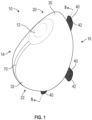
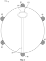
- Figure 1 illustrates a perspective view of a tissue expansion device 10 that can be used for temporary surgical implantation in a patient, preliminary to another procedure, such as breast augmentation, breast reconstruction, or skin grafting.
- the tissue expansion device 10 can be placed beneath the skin and left in place for a period of time to permit overlying tissue and skin to grow or adjust to a given volume of the tissue expansion device 10.
- a clinician can inject or fill the tissue expansion device 10 with a fluid via an injection port 12 of the device 10.
- a clinician can use a needle of a syringe to pierce the tissue expansion device 10 within the injection port 12 in order to fill the device 10.
- the injection port 12 can provide controllable flow into or out of the tissue expansion device 10. Further, the injection port 12 can be self-sealing upon removal of the needle.
- the tissue expansion device 10 can comprise an anterior portion 14, a posterior portion 16, an upper pole 20, and a lower pole 22. Further, the tissue expansion device 10 can also comprise an expandable shell 30.
- the expandable shell 30, or portions thereof, can be formed from a biocompatible polymer material such as silicone rubber, a laminate of various forms of silicone, silicone copolymers, polyurethane, and various other elastomers in various combinations.
- the expandable shell 30 of the tissue expansion device 10 can define a midpoint or center position 18 that lies at a position between the upper pole 20 and the lower pole 22.
- the center position 18 of the expandable shell 30 can be located at a geometric center of a circular shell.
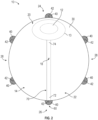
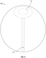
- Figure 2 illustrates that the center position 18 is located at a midpoint of the diameter between opposing edges, circumference, or boundaries of the expandable shell 30.
- the center position 18 need not represent a geometric center of the shell; for example, the center position 18 can represent a midpoint along a line (e.g., a height dimension or diameter) extending from an edge of a top portion 24 of the shell 30 to an edge of a bottom portion 26 of the shell 30.
- a line e.g., a height dimension or diameter
- an outer surface 32 of the shell 30 can have a smooth or glossy finish.
- the device 10 can be round, circular, oval, crescent-shaped, anatomically shaped, or other suitable shapes in order to mimic a natural or desired breast shape.
- the tissue expansion device 10 can comprise a plurality of tabs 40 coupled to the posterior portion 16 of the shell 30.
- the tabs 40 can be used by the clinician to anchor, engage, or secure the tissue expansion device 10 relative to the surrounding tissue at the implantation site of the patient.
- the tabs 40 can optionally comprise an aperture 42 through which a suture or other fastening means can be coupled to the tab 40 to facilitate anchoring of the tissue expansion device 10 to the patient's tissue.
- the tabs 40 can be circumferentially spaced apart about the posterior portion of the shell 30.
- the tabs 40 can extend in radially outward direction relative to the center position 18 of the expandable shell 30.
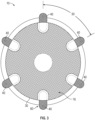
- the tabs 40 can be circumferentially spaced apart at an angle 50 of approximately 60°.
- the tabs can be spaced apart at an angle 50 that is based on or corresponds to the number of tabs.
- the tabs can be equally circumferentially spaced apart depending on the number of tabs (e.g., the tabs are circumferentially spaced apart at an angle equal to 360 degrees divided by the number of tabs), as in the embodiment illustrated in Figure 3 .
- the six tabs 40 are positioned circumferentially about the posterior portion of the shell at a 12 o'clock position, a 2 o'clock position, a 4 o'clock position, a 6 o'clock position, an 8 o'clock position, and a 10 o'clock position, respectively.
- one or more of the tabs can comprise an attribute that is different from an attribute of one or more of the other tabs.
- the attribute may comprise at least one of a color of a tab, a size of a tab, a shape of the tab, or a material of a tab.
- One or more of the tabs can be differently colored or have a different shape, size, or material than the one or more of the other tabs.
- one or more of the tabs can be white, tan, yellow, orange, red, pink, purple, blue, green, brown, gray, black, and/or any shades thereof.
- a 6 o'clock tab 60 can be white in color while the remainder of the tabs, positioned at 12 o'clock, 2 o'clock, 4 o'clock, 8 o'clock, and 10 o'clock positions, can be blue.
- all of the tabs except for one may be white, while the other tab has a non-white color.
- one or more of the tabs can be a first color
- one or more of the tabs can be a second color
- or more of the tabs can be a third color
- one or more the tabs can be a fourth color
- one or more of the tabs can be a fifth color
- one or more of the tabs can be a sixth color.
- the distinguishing attribute(s) of one or more tabs can help a clinician when placing the device 10 within the patient.
- the tabs 40 can help a clinician to identify or discern the top portion 24, and/or bottom portion 26, and/or a lateral portions 28 of the device 10.
- the clinician can recognize that the top portion 24 is adjacent the upper pole 20, the bottom portion 26 is adjacent the lower pole 22, and the lateral portions 28 are positioned between the top and bottom portions, which can assist the clinician in positioning or aligning the device 10, thereby ensuring that the shape of the device 10 is properly aligned relative to the patient's body.
- certain attributes, such as the color, texture, or shape of the tabs can be modified or designed so as to help the clinician quickly identify the section or portion of the device 10 at which a given tab resides.
- a plurality of tabs can be disposed about the top portion 24, the bottom portion 26, and/or the lateral portions 28 of the shell 30.
- six tabs are spaced at 12 o'clock, 2 o'clock, 4 o'clock, 6 o'clock, 8 o'clock, and 10 o'clock positions, the tabs at the 4 o'clock, 6 o'clock, 8 o'clock positions can be a first color while the tabs at the 2 o'clock and 10 o'clock positions can be a second color.
- the 12 o'clock tab can be either the first or second color.
- the tabs at the 4 o'clock, 6 o'clock, and 8 o'clock positions can serve to indicate a top or bottom of the device 10.
- the 12 o'clock tab is the first color (the same color as the tabs at the 4 o'clock, 6 o'clock, and 8 o'clock positions)
- the clinician may be able to easily discern both the top and bottom of the device 10, as well as the alignment of the device 10.
- the color scheme may vary such that the tabs at the 4 o'clock and 8 o'clock positions have a different color than the remainder of the tabs.
- the tissue expansion device 10 can also comprise an orientation indicator 70.
- an orientation indicator 70 As noted above, the present disclosure notes the realization that if anatomically shaped, breast implants are generally symmetrical about a centerline and therefore, require the surgeon to be aware of that centerline so the device is implanted in the proper orientation. Although certain tissue expansion devices have previously incorporated raised silicone dots on the surface of the shell to provide palpable and visual indicators or visible lines on the shell of contrasting color, such as blue or white, to indicate the centerline, these dots or lines are applied to the implant shell during secondary assembly operations. Thus, the cost for manufacturing is high and the additional material or color can be lost or may be inaccurately applied.
- the manufacturing process that creates indicator dots and lines may be inadequate or inaccurate, which inaccuracies can be difficult for the clinician to appreciate or overcome.
- the present disclosure provides a solution that creates an orientation indicator 70 that is formed with and/or along an inner surface of the shell 30, thereby avoiding the additional manufacturing costs and ensuring that the orientation indicator 70 is accurately placed relative to the shell 30 and its shape.
- the orientation indicator 70 is visible along the anterior portion 14 of the shell 30.
- the orientation indicator 70 can be disposed along the lower pole 22 of the shell 30.
- the orientation indicator 70 can also extend along the upper pole 20 of the shell 30.
- the orientation indicator 70 can extend along both the upper pole 20 and the lower pole 22.
- the orientation indicator 70 can extend to and/or beyond the center position 18 of the shell 30. Further, the orientation indicator 70 can extend through and beyond, through, or only up to the injection port 12.
- the orientation indicator 70 can extend as a vertical line along a vertical dimension. However, the orientation indicator 70 can also extend as a generally horizontal line along a horizontal dimension. The longitudinal extent of the orientation indicator 70 can correspond to a vertical or horizontal dimension. For example, referring to the front view of Figure 2 , the orientation indicator 70 can extend from the lower portion 26, upwardly across at least 50% of the diameter or height of the expandable shell 30.
- the orientation indicator 70 can extend up to about 50%, at least about 50%, at least about 55%, at least about 60%, at least about 65%, at least about 70%, at least about 75%, at least about 80%, at least about 85%, at least about 90%, at least about 95%, or up to the entirety of a given dimension, diameter, or height of the expandable shell 30.
- the width, patterning, shape, and/or longitudinal extent of the orientation indicator 70 can advantageously be designed to provide a ready visual tool for placing and aligning the device 10. This dedicated feature provide unique, cost-effective advantages from both manufacturing and clinical perspectives.
- the orientation indicator 70 can provide one or more geometric patterns or shapes that can allow the clinician to identify an aspect of and/or the orientation of the tissue expansion device 10 during implantation of the device 10 within a cavity of a patient.
- the orientation indicator 70 can comprise a band, strip, or line that extends along and is visible along the shell 30. Further, the orientation indicator 70 can be aligned with one or more components or aspects of the tissue expansion device 10. For example, the orientation indicator 70 can be aligned with at least one of the plurality of tabs 40. If a line or linear pattern, the orientation indicator 70 can extend along a vertical, horizontal, or other axis.
- the visual perception of the orientation indicator 70 can enable a clinician to adjust a position of the tissue expansion device 10 within the cavity by aligning the orientation indicator 70 relative to a horizontal or vertical plane or other indicia.
- the embodiment shown in Figure 2 illustrates that the orientation indicator 70 extends along a generally vertical plane between an edge of the shell 30 adjacent to the 6 o'clock tab 60 and the injection port 12.
- the orientation indicator 70 can extend partially or fully along such a path, along the lower pole 22 of the shell 30.
- the orientation indicator 70 can extend along the upper pole 20 along the same vertical plane.
- the embodiment illustrated in Figure 2 advantageously provides a clear indication to the clinician as to the orientation of the tissue expansion device 10 because it appears in only the lower pole 22 and also provides a sufficiently long line as a visual indicator.
- the orientation indicator 70 comprises a line having a first end portion 72 adjacent to an edge of the shell 30 and a second end portion 74 distal to the edge of the shell.
- the injection port 12 can intersect with the second end portion of the orientation indicator 70.
- the second end portion 74 of the orientation indicator extends to or is aligned with an outer perimeter 13 of the injection port 12.
- the orientation indicator 70 can also be used to facilitate manufacturing of the device 10.
- the orientation indicator 70 can be used to increase the manufacturing efficiency and accuracy of each device 10, as well as the manufacturing consistency between multiple devices 10.
- the injection port 12 can be positioned along the shell 30 by aligning a portion of the injection port 12 with a portion of orientation indicator 70.
- the outer perimeter 13 e.g., a lowermost portion of the perimeter or a central portion
- the injection port 12 can be placed so as to abut or otherwise be aligned with the second end portion 74 of the orientation indicator.
- the tabs 40 can be coupled to the shell 30 by an adhesive or co-molded with a portion of the shell 30.
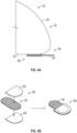
- Figures 4A and 4B illustrate a side view and perspective assembly views of a tab 40.
- Figure 4A illustrates the 6 o'clock tab 60 and its engagement structure 80 in side view.
- Figure 4B illustrates an exploded view and an assembly view of the engagement structure 80 with the tab 40.
- the engagement structure 80 can comprise upper and lower engagement layers 82, 84 that sandwich the tab 40 therebetween.
- the engagement structure 80 and the tab 40 can be attached to the shell 30 and vulcanized.
- the tabs 40 can comprise a surface structure or mesh pattern along an outer surface thereof, which can assist in grasping the tab 40 in order to manipulate a position of the device 10 and two further enhance engagement with the upper and lower engagement layers 82, 84. As shown in Figure 4A , the engagement structure 80 and the tab 40 can be coupled to the posterior portion 16 of the shell 30.
- Figures 5 and 6 illustrate side cross-sectional views of the tissue expansion device 10 in an assembled and an exploded state, respectively.
- the injection port 12 of the device 10 be positioned within a cavity 90 of the shell 30.
- the injection port 12 can comprise an injection reservoir assembly 100 that is coupled to an inner surface 102 of the shell 30.
- the injection reservoir assembly 100 can be fabricated similar to that disclosed in U.S. Patent No. 4,671,255 , which is owned by the present applicant, the entirety of which is incorporated herein by reference.
- the injection reservoir assembly 100 can comprise an injection reservoir 110 that is coupled to or laminated onto the inner surface 102 of the shell 30.
- the injection reservoir assembly 100 can provide a self-sealing valve or injection port that will tend to seal any puncture or opening created by a needle when it is advanced into and later withdrawn from the injection port 12.
- Figure 5 shows the upper pole 20 positioned between the center position 18 of the shell 30 and a top edge of the shell 30 at the top portion 24, and the lower pole 22 positioned between the center position 18 of the shell 30 and a bottom edge of the shell 30 at the bottom portion 26.
- the injection port 12 can be positioned entirely within the upper pole 20. In some embodiments, however, only a portion of the injection port 12 can be positioned within the upper pole 20, with a portion of the injection port 12 extending across the center position 18. In some embodiments, at least 50% of the injection port 12 is positioned within the upper pole 20.
- the orientation indicator 70 can extend from the injection port 12 toward the bottom edge of the shell 30, as shown in the front view of the device 10 in Figure 2 . Further, in some embodiments, the orientation indicator 70 can extend from the injection port 12 toward another edge of the shell 30, such as the top edge or a lateral edge of the shell 30. Additionally, in some embodiments, the orientation indicator 70 can extend from the injection port 12 across a portion of the upper pole 20 and across the lower pole 22.
- the injection reservoir 110 can be coupled to the inner surface 102 via a coupling layer 112.
- the coupling layer 112 can comprise a reinforced ring 114 and a filler plug 116.
- the reinforced ring 114 can comprise a mesh or fabric material that is co-molded with a polymer, such as silicone.
- the reinforced ring 114 can serve to increase the durability of the injection reservoir assembly 100.
- the reinforced ring 114 can optionally be configured as a tear-resistant layer.
- the injection reservoir 110 can include reservoir body 111 and a flange 113 that extends radially outward from the reservoir body 111.
- the flange 113 can comprise a thickness that tapers away from the reservoir body 111.
- the reservoir body 111 can form an intermediate perimeter of the injection reservoir 110, while the flange 113 can form or extend along the outer perimeter 13 of the injection port.
- the orientation indicator 70 is used as a reference point during manufacturing, e.g., to position the injection port 12, the flange 113 can be positioned to align with the second end portion 74 of the orientation indicator when coupling the injection reservoir 110 to the device 10.
- the tapered flange 113 can provide a flexible (or alternatively, a more rigid) portion of the injection reservoir 110.
- the flange 113 can flex, relative to the reservoir body 111, thereby providing a smooth, less abrupt transition between the injection reservoir 110 and the adjacent portion of the device 10.
- a force such as a bending force or a point stress exerted against the shell 30
- the flange 113 can tend to flex or provide a rigid, tactilely discernible perimeter for the injection port 12.
- the flange 113 provide an increased surface area, relative to the reservoir body 111, to couple the injection reservoir 110 to the inner surface 102 of the shell, thereby advantageously ensuring a greater seal between the injection reservoir 110 and the inner surface 102.
- the material, structure, and radial extent of the flange 113 can be selected so as to provide a desired amount of surface area and a desired structural behavior for the injection port 12.
- the tissue expansion device 10 can also comprise a stable base 120 that is coupled to the inner surface 102 of the shell 30 along the posterior portion 16 of the shell.
- the shell 30 can comprise a mandrel aperture 122 that extends through the posterior portion of the shell 30.
- the stable base 120 can be coupled to the posterior portion 16 and provide structural support thereto, especially around the mandrel aperture 122.
- the tissue expansion device can comprise a filler plug 124 and a patch 126 that can be used to fill and seal the mandrel aperture 122.
- the shell 30 can comprise an opaque or translucent appearance.
- the shell 30 can be fabricated such that the inner surface 102 comprises a roughened texture. Thus, light passing through the shell 30 will be diffracted and the passage of light will be impeded, thus achieving an opaque or translucent appearance of the shell 30.
- the reinforced ring 114 may be configured to include a mesh pattern that can tend to mask or disguise any visual imperfections in the lamination process.
- the stable base 120 comprises a textured inner surface 130.
- the textured inner surface 130 can provide a visually similar appearance to the mesh pattern of the reinforced ring 114. Because the laminated stable base 120 and inner surface 102 will provide a generally transparent view of the textured inner surface 130, the tissue expansion device can be provided with a consistent pattern along the injection port 12 in the anterior portion 114 of the device 10, the posterior portion 16, and the tabs 40. Further, although the pattern in the illustrated embodiment is discussed as being a mesh pattern, other patterns can provided. Further, the pattern of the textured inner surface 130 can also be selected to be distinct from the pattern provided by the reinforced ring 114 at the injection port 12 and/or the tabs 40.
- the shell 30 has a thickness extending between the outer surface and the inner surface 102 of the shell.
- the thickness of the shell can be approximately constant along each of the anterior portion 14 and the posterior portion 16 of the device.
- the constant thickness of the shell 30 can provide consistent light penetration and/or diffraction through the shell 30, and can provide consistent resistance along all portions of the shell 30.
- the thickness of the shell 30 can increase and/or decrease along any portion thereof.
- the thickness of the shell 30 can decrease from the anterior portion 114 toward the posterior portion 16.
- the thickness of the shell 30 can decrease from the lower pole 22 toward the upper pole 20.
- Such variations in thickness can advantageously provide desired tactile feedback to assist the clinician in aligning the device 10 relative to the anatomy of the patient.
- the device 10 When viewed in cross-section, such as shown in Figure 5 , the device 10 has a width extending between the posterior portion 16 and the anterior portion 14. The width of the device 10 tapers from the lower pole 22 toward the upper pole 20. In some embodiments, when moving from the bottom portion 26 toward the top portion 24, the width of the device 10 increases along the lower pole 22, and then the width of the device 10 decreases along the upper pole 20. In some embodiments, the device 10 has a maximum width at the lower pole 22, proximal to the center position 18, and a minimum width at the upper pole 20, adjacent to the top portion 24.
- the outer surface of the shell 30 along the anterior portion 14, can comprise a generally convex shape.
- a portion of the shell 30 can have a convex shape or a concave shape.
- the outer surface of the shell 30 along a portion of the lower pole 22 can be convex, while the outer surface of the shell 30 along a portion of the upper pole 20 can be concave.
- the outer surface of the shell 30 transitions from a convex shape to a concave shape along a portion of the upper pole 20.
- a mandrel 150 is illustrated that can be used in fabricating at least one embodiment disclosed herein.
- the casting tool or mandrel 150 can comprise an outer surface 152.
- the mandrel 150 can be coupled to another tool or support apparatus using a coupling recess 154 of the mandrel.
- the coupling recess 154 is positioned at the center 156 of the mandrel.
- the coupling recess 154 can correspond to the mandrel aperture 122 of a shell, and the center 156 of the mandrel can correspond to the center position 18 of a shell, such as the shell 30 discussed in the embodiment of Figures 1-6 .
- the outer surface 152 can have a smooth region 160 and a roughened region 162.
- the smooth region 160 can correspond to an orientation indicator, such as the orientation indicator 70 discussed in the embodiment of Figures 1-6 .
- a roughened region of the outer surface 152 can correspond to an orientation indicator, and another portion of the outer surface 152 can have a smooth region.
- Figure 7B also demonstrates how the smooth region 160, which can correspond to an orientation indicator, extends across the center 156 of the mandrel, which can correspond to a center position 18 of a shell.
- the mandrel 150 can be dipped into a polymer solution and subsequently dried, which can produce a shell.
- the shell will have a shape consistent with the shape of the outer surface 152 of the mandrel 150.
- the shell can have an inner surface that corresponds to the smooth region 160 and the roughened region 162 of the outer surface 152 of the mandrel 150. In this manner, a desired texture of the inner surface 102 of the shell 30 discussed above, as well as any shape or pattern of the orientation indicator 70, can be achieved. In this manner, various advantages can be achieved over prior devices and methods of manufacture.
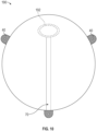
- Figures 8 , 9 , and 10 illustrate different embodiments of the tissue expansion device 10.
- Figure 8 illustrates an embodiment of a tissue expansion device 170 that comprises a plurality of tabs 40, an orientation indicator 70, and other such features similar to the tissue expansion device 10, details of which will not be discussed herein for brevity, but are incorporated by reference from the disclosure above.
- the device 170 can be configured to comprise an injection port 172 having a visible or tactile outer ring 174.
- the injection port 172 can be compact and have a coupling area along the outer ring 174 that is smaller in size than that of the injection port 12.
- a tissue expansion device 180 in which the device 180 does not comprise tabs.
- the device 180 can be similar to those discussed above with respect to the device 10 and are not discussed herein for brevity, but are incorporated by reference from the disclosure above.
- the device 180 can be manufactured and used without the tabs disclosed above with respect to the device 10.
- the device 180 can be configured without any tabs, other embodiments can be configured to include one or more tabs, as disclosed herein.
- Figure 10 illustrates an embodiment of a tissue expansion device 190 that comprises three tabs that are circumferentially offset at 120° from each other.
- the device 190 can be similar to those discussed above with respect to the device 10 and are not discussed herein for brevity, but are incorporated by reference from the disclosure above.
- the injection port 192 can form a transparent or opaque, nonwhite portion of the device 190 without any underlying pattern from a reinforced ring.
- the device 190 can be configured to comprise a corresponding or different appearance of the posterior portion and/or tabs of the device relative to the injection port 192.
- any of the clauses herein may depend from any one of the independent clauses or any one of the dependent clauses.
- any of the clauses e.g., dependent or independent clauses
- a claim may include some or all of the words (e.g., steps, operations, means or components) recited in a clause, a sentence, a phrase or a paragraph.
- a claim may include some or all of the words recited in one or more clauses, sentences, phrases or paragraphs.
- some of the words in each of the clauses, sentences, phrases or paragraphs may be removed.
- additional words or elements may be added to a clause, a sentence, a phrase or a paragraph.
- the subject technology may be implemented without utilizing some of the components, elements, functions or operations described herein. In one aspect, the subject technology may be implemented utilizing additional components, elements, functions or operations.
- a tissue expansion device for temporary surgical implantation beneath skin of a patient and for removal upon predetermined expansion of overlying tissue, the device comprising: an expandable shell forming an expandable chamber, the shell having an anterior portion and a posterior portion; an orientation indicator visible along the anterior portion of the expandable shell, wherein, when the expandable shell expandable shell is viewed from the front, the orientation indicator extends across at least 50% of a vertical dimension of the expandable shell; and an injection port, coupled to the anterior portion of the shell, in fluid communication with the chamber and configured to permit injection of fluid into the chamber from a hypodermic needle.
- Clause 2 The device of Clause 1, further comprising a plurality of tabs coupled to the posterior portion of the shell.
- Clause 3 The device of Clause 1, further comprising a plurality of tabs disposed about top, bottom, and lateral portions of the expandable shell.
- Clause 4 The device of Clause 2, wherein each of the plurality of tabs extends in radially outward direction relative to a center position of the device.
- Clause 5 The device of any one of Clauses 2 ⁇ 1, wherein the plurality of tabs comprises six tabs.
- Clause 6 The device of any one of Clauses 2-5, wherein the plurality of tabs comprises six tabs, and wherein the six tabs are positioned circumferentially about the posterior portion of the shell at a 12 o'clock position, a 2 o'clock position, a 4 o'clock position, a 6 o'clock position, an 8 o'clock position, and a 10 o'clock position, respectively.
- Clause 7 The device of any one of Clauses 2-6, wherein at least one of the plurality of tabs comprises an attribute different from an attribute of a remainder of the plurality of tabs.
- Clause 8 The device of Clause 7, wherein the attribute comprises at least one of a color of the tab, a size of the tab, a shape of the tab, or a material of the tab.
- Clause 9 The device of any one of Clauses 2-8, wherein the plurality of tabs comprises six tabs, and wherein a first of the six tabs has a first color and a remainder of the six tabs has a second color.
- Clause 10 The device of Clause 9, wherein the first of the six tabs is positioned at a bottom portion of the expandable shell.
- Clause 11 The device of any one of Clauses 2-10, wherein each of the plurality of tabs comprises an aperture for receiving a suture therethrough.
- Clause 13 The device of any one of Clauses 1-12, wherein the orientation indicator comprises a line.
- Clause 14 The device of any one of Clauses 1-13, wherein the orientation indicator comprises a line extending from the injection port toward an edge of the shell.
- Clause 15 The device of any one of Clauses 1-14, wherein the orientation indicator extends across at least about 50% of a dimension of the expandable shell.
- Clause 16 The device of any one of Clauses 1-15, wherein the orientation indicator extends across at least about 55% of a dimension of the expandable shell.
- Clause 17 The device of any one of Clauses 1-16, wherein the orientation indicator extends across at least about 60% of a dimension of the expandable shell.
- Clause 18 The device of any one of Clauses 1-17, wherein the orientation indicator extends across at least about 65% of a dimension of the expandable shell.
- Clause 19 The device of any one of Clauses 1-18, wherein the orientation indicator extends across at least about 70% of a dimension of the expandable shell.
- Clause 20 The device of any one of Clauses 1-19, wherein the orientation indicator extends across at least about 75% of a dimension of the expandable shell.
- Clause 21 The device of any one of Clauses 1-17, wherein the orientation indicator extends across a center position of the expandable shell.
- Clause 22 The device of any one of Clauses 1-14, wherein the orientation indicator extends across at least about 50% of a vertical dimension of the expandable shell.
- Clause 23 The device of Clause 1, further comprising a plurality of tabs coupled to the posterior portion of the shell, wherein a first tab of the plurality of tabs is coupled to the shell at a 6 o'clock position, and wherein the orientation line extends from the injection port toward the first tab at the 6 o'clock position.
- Clause 24 The device of Clause 1, further comprising a plurality of tabs coupled to the posterior portion of the shell, wherein the orientation indicator is aligned with at least one of the plurality of tabs.
- Clause 25 The device of any one of Clauses 1-24, wherein the orientation indicator comprises a surface texture of the expandable shell.
- Clause 26 The device of any one of Clauses 1-25, wherein the orientation indicator comprises a surface texture of an interior surface of the expandable shell.
- Clause 27 The device of any one of Clauses 1-26, wherein an exterior surface of the expandable shell comprises a smooth finish, the orientation indicator comprises a smooth finish on an interior surface of the expandable shell, and a remainder of the interior surface of the expandable shell comprises a roughened finish.
- Clause 28 The device of any one of Clauses 1-27, wherein the orientation indicator comprises a line having a first end portion adjacent to an edge of the shell and a second end portion distal to the edge of the shell, and wherein the second end portion intersects the injection port.
- Clause 29 The device of Clause 28, wherein the second end portion of the orientation indicator is aligned with an outer perimeter of the injection port.
- Clause 30 The device of any one of Clauses 1-29, wherein the orientation indicator is a transparent portion of the shell.
- Clause 32 A method of implanting the tissue expansion device of any of the preceding Clauses, the method comprising: positioning the tissue expansion device within a cavity of a patient; and adjusting a position of the tissue expansion device within the cavity by aligning an orientation indicator relative to a horizontal or vertical plane.
- tissue expansion device comprises a plurality of tabs coupled to a posterior portion thereof, and wherein the orientation indicator is aligned with a first tab of the plurality of tabs located at a 6 o'clock position, and the adjusting comprises aligning the orientation indicator and the first tab relative to a vertical plane.
- a method of manufacturing a tissue expansion device comprising: dipping a casting tool into a polymer solution to form a shell along an outer surface of the casting tool, the casting tool outer surface having a textured portion and a smooth portion; permitting the shell to dry; and removing the shell from the casting tool, the shell having an inner surface comprising a first portion corresponding to the textured portion and a second portion corresponding to the smooth portion, the shell having a smooth outer surface, wherein the smooth outer surface of the shell and the second portion collectively define a transparent orientation indicator, and wherein the smooth outer surface of the shell and the first portion of the shell inner surface collectively define a translucent or opaque section of the shell that visually contrasts against the transparent orientation indicator, wherein the orientation indicator extends across at least 50% of a diameter of the expandable shell.
- Clause 36 The method of Clause 35, further comprising coupling a plurality of tabs to a posterior portion of the shell .
- Clause 37 The method of Clause 36, wherein the coupling comprises coupling the plurality of tabs circumferentially about the posterior portion of the shell at a 12 o'clock position, a 2 o'clock position, a 4 o'clock position, a 6 o'clock position, an 8 o'clock position, and a 10 o'clock position, respectively.
- Clause 38 The method of Clause 37, wherein a first tab of the plurality of tabs comprises an attribute different from an attribute of a remainder of the plurality of tabs, and wherein the method further comprises positioning the first tab at a 6 o'clock position on the posterior portion of the shell.
- Clause 39 The method of Clause 38, wherein the attribute comprises at least one of a color of the tab, a size of the tab, a shape of the tab, or a material of the tab .
- Clause 40 The method of any of Clauses 35-39, further comprising coupling an injection reservoir assembly to the shell inner surface at an injection port section of the shell inner surface to change the translucent or opaque section to transparent along the injection port section.
- Clause 41 The method of Clause 40, wherein the injection reservoir assembly comprises a reinforced ring having a first pattern formed therein, the first pattern being visible through the transparent injection port section when the injection reservoir assembly is coupled to the shell.
- Clause 42 The method of Clause 41, wherein the first pattern comprises a mesh pattern.
- Clause 43 The method of any of Clauses 35-42, further comprising coupling a stable base to the shell inner surface along a posterior portion of the shell to change the translucent or opaque section to transparent along a section of the posterior portion.
- Clause 44 The method of Clause 43, wherein the stable base comprises a patterned internal surface having a second pattern formed therein, the second pattern being visible through the transparent section of the posterior portion when the stable base is coupled to the shell.
- Clause 45 The method of Clause 44, wherein the second pattern comprises a mesh pattern.
- Clause 46 The method of any of Clauses 35-45, further comprising coupling an injection reservoir assembly to the shell inner surface at an injection port section of the shell, wherein coupling the injection reservoir assembly comprises aligning an outer perimeter of the injection reservoir with an end portion of the orientation indicator.
- the phrase "at least one of' preceding a series of items, with the term “and” or “or” to separate any of the items, modifies the list as a whole, rather than each member of the list (i.e., each item).
- phrases “at least one of A, B, and C” or “at least one of A, B, or C” each refer to only A, only B, or only C; any combination of A, B, and C; and/or at least one of each of A, B, and C.
- top should be understood as referring to an arbitrary frame of reference, rather than to the ordinary gravitational frame of reference.
- a top surface, a bottom surface, a front surface, and a rear surface may extend upwardly, downwardly, diagonally, or horizontally in a gravitational frame of reference.
Landscapes
- Health & Medical Sciences (AREA)
- Life Sciences & Earth Sciences (AREA)
- Animal Behavior & Ethology (AREA)
- Veterinary Medicine (AREA)
- Public Health (AREA)
- Oral & Maxillofacial Surgery (AREA)
- General Health & Medical Sciences (AREA)
- Engineering & Computer Science (AREA)
- Biomedical Technology (AREA)
- Heart & Thoracic Surgery (AREA)
- Surgery (AREA)
- Transplantation (AREA)
- Dermatology (AREA)
- Cardiology (AREA)
- Vascular Medicine (AREA)
- Molecular Biology (AREA)
- Medical Informatics (AREA)
- Pathology (AREA)
- Nuclear Medicine, Radiotherapy & Molecular Imaging (AREA)
- Prostheses (AREA)
- Media Introduction/Drainage Providing Device (AREA)
- Infusion, Injection, And Reservoir Apparatuses (AREA)
Applications Claiming Priority (3)
| Application Number | Priority Date | Filing Date | Title |
|---|---|---|---|
| US201862731033P | 2018-09-13 | 2018-09-13 | |
| EP19778772.4A EP3849458A1 (de) | 2018-09-13 | 2019-09-13 | Gewebeexpansionsvorrichtung |
| PCT/US2019/051171 WO2020056369A1 (en) | 2018-09-13 | 2019-09-13 | Tissue expansion device |
Related Parent Applications (1)
| Application Number | Title | Priority Date | Filing Date |
|---|---|---|---|
| EP19778772.4A Division EP3849458A1 (de) | 2018-09-13 | 2019-09-13 | Gewebeexpansionsvorrichtung |
Publications (2)
| Publication Number | Publication Date |
|---|---|
| EP4461264A2 true EP4461264A2 (de) | 2024-11-13 |
| EP4461264A3 EP4461264A3 (de) | 2025-01-01 |
Family
ID=68069924
Family Applications (2)
| Application Number | Title | Priority Date | Filing Date |
|---|---|---|---|
| EP24189340.3A Pending EP4461264A3 (de) | 2018-09-13 | 2019-09-13 | Gewebeexpansionsvorrichtung |
| EP19778772.4A Withdrawn EP3849458A1 (de) | 2018-09-13 | 2019-09-13 | Gewebeexpansionsvorrichtung |
Family Applications After (1)
| Application Number | Title | Priority Date | Filing Date |
|---|---|---|---|
| EP19778772.4A Withdrawn EP3849458A1 (de) | 2018-09-13 | 2019-09-13 | Gewebeexpansionsvorrichtung |
Country Status (5)
| Country | Link |
|---|---|
| US (2) | US11160630B2 (de) |
| EP (2) | EP4461264A3 (de) |
| JP (3) | JP7153790B2 (de) |
| CA (1) | CA3112634A1 (de) |
| WO (1) | WO2020056369A1 (de) |
Families Citing this family (14)
| Publication number | Priority date | Publication date | Assignee | Title |
|---|---|---|---|---|
| BR112015005695B1 (pt) * | 2012-09-17 | 2021-11-09 | Veriteq Acquisition Corporation | Método de fabricação de implantes mamários com transponders integrados |
| US9532867B2 (en) | 2013-07-11 | 2017-01-03 | Tepha, Inc. | Absorbable implants for plastic surgery |
| IL316656A (en) | 2016-02-09 | 2024-12-01 | Estab Labs S A | Transponders and sensors for implantable medical devices and methods of using them |
| IL265954B2 (en) | 2016-10-28 | 2024-03-01 | Estab Labs S A | Tissue expanders, production methods and patterns thereof |
| ES2953544T3 (es) | 2018-02-09 | 2023-11-14 | Tepha Inc | Implante mamario de contorno completo |
| USD892329S1 (en) | 2018-07-03 | 2020-08-04 | Tepha, Inc. | Three dimensional mastopexy implant |
| WO2020021482A2 (en) * | 2018-07-25 | 2020-01-30 | Establishment Labs S.A. | Implants with symmetric shape |
| CA3112634A1 (en) * | 2018-09-13 | 2020-03-19 | Allergan, Inc. | Tissue expansion device |
| WO2020072349A1 (en) * | 2018-10-02 | 2020-04-09 | Tepha, Inc. | Medical devices to limit movement of breast implants |
| US11259913B2 (en) * | 2019-02-06 | 2022-03-01 | Susan Scott | Breast implant with position marker |
| MX2022006292A (es) | 2019-11-25 | 2022-08-15 | Tepha Inc | Envolturas de implantes de mama que limitan el movimiento de los implantes de mama, y metodos relacionados. |
| WO2021217099A1 (en) | 2020-04-24 | 2021-10-28 | Allergan, Inc. | Drain-compatible tissue expansion device |
| US11357614B1 (en) * | 2021-06-11 | 2022-06-14 | Marcel Malek | Breast implant |
| CN115919479A (zh) * | 2022-09-29 | 2023-04-07 | 上海交通大学医学院附属第九人民医院 | 一种无注射座防渗漏软组织扩张器及其制备方法和应用 |
Citations (1)
| Publication number | Priority date | Publication date | Assignee | Title |
|---|---|---|---|---|
| US4671255A (en) | 1985-10-16 | 1987-06-09 | Mcghan Medical Corporation | Tissue expander with self-contained injection reservoir and reinforcing insert |
Family Cites Families (198)
| Publication number | Priority date | Publication date | Assignee | Title |
|---|---|---|---|---|
| FR587637A (fr) | 1923-12-29 | 1925-04-21 | Dispositif pour le moulage des tubes et étuis en gélatine et autres matières | |
| BE451282A (de) | 1943-03-31 | |||
| US3204959A (en) | 1961-03-16 | 1965-09-07 | Mettoy Co Ltd | Hollow inflatable article |
| DE1223991B (de) | 1963-11-22 | 1966-09-01 | Scholl Werke G M B H Fuer Fabr | Verfahren und Vorrichtung zur Herstellung von Schutzringen mit abgerundeter oberer Randkante fuer druckempfindliche Stellen, wie Huehneraugen, Hautverhornungen u. dgl. |
| US3301251A (en) | 1964-09-04 | 1967-01-31 | Heatovent Electric Ltd | Storage block adapted for storage and exchange of heat |
| US3577836A (en) | 1969-11-12 | 1971-05-11 | Raymond M Tamura | Armored garment |
| US3852832A (en) | 1972-10-24 | 1974-12-10 | Heyer Schulte Corp | Prosthesis with fixation means |
| US3919724A (en) | 1974-06-07 | 1975-11-18 | Medical Eng Corp | Implantable prosthesis having a self-sealing valve |
| US4195639A (en) | 1976-03-05 | 1980-04-01 | Lee Denis C | External breast prosthesis |
| US4125117A (en) * | 1977-02-16 | 1978-11-14 | Lee Denis C | External breast prosthesis |
| US4157085A (en) | 1978-03-24 | 1979-06-05 | Dow Corning Corporation | Surgically implantable tissue expanding device and the method of its use |
| US4190040A (en) | 1978-07-03 | 1980-02-26 | American Hospital Supply Corporation | Resealable puncture housing for surgical implantation |
| US4200098A (en) | 1978-10-23 | 1980-04-29 | Alza Corporation | Osmotic system with distribution zone for dispensing beneficial agent |
| US4264990A (en) | 1979-01-24 | 1981-05-05 | Hamas Robert S | Mammary prosthesis |
| US4428364A (en) | 1979-04-11 | 1984-01-31 | Dow Corning Corporation | Self-sealing injection button and method of making same |
| US4455691A (en) | 1979-10-03 | 1984-06-26 | Minnesota Mining And Manufacturing Company | Silicone gel filled prosthesis |
| US4650487A (en) | 1980-10-27 | 1987-03-17 | Memorial Hospital For Cancer And Allied Diseases | Multi-lumen high profile mammary implant |
| US4332634A (en) | 1981-01-14 | 1982-06-01 | Medical Engineering Corporation | Method of preparing a resealable valve |
| US4773909A (en) | 1981-10-06 | 1988-09-27 | Memorial Hospital For Cancer And Allied Diseases | Multi-lumen high profile mammary implant |
| US4605412A (en) | 1983-01-20 | 1986-08-12 | Medical Engineering Corp. | Mammary prosthesis having adjustable projection |
| US4636213A (en) | 1985-01-24 | 1987-01-13 | Pakiam Anthony I | Implantable prosthesis |
| US4685447A (en) | 1985-03-25 | 1987-08-11 | Pmt Corporation | Tissue expander system |
| US4738657A (en) | 1985-09-30 | 1988-04-19 | Mcghan Medical Corporation | Self-sealing injection reservoir |
| US4840615A (en) | 1985-09-30 | 1989-06-20 | Mcghan Medical Corporation | Self-sealing injection reservoir |
| US4662357A (en) | 1986-01-21 | 1987-05-05 | Dow Corning Corporation | Inflatable surgical implant with variable inflation position |
| US4823815A (en) | 1986-09-19 | 1989-04-25 | Mentor Corporation | Tissue expanding device and method of making same |
| AU617667B2 (en) | 1986-11-04 | 1991-12-05 | Allergan, Inc. | Open-cell, silicone-elastomer medical implant and method for making |
| CA1322441C (en) | 1986-11-04 | 1993-09-28 | Joel Quaid | Open-cell, silicone-elastomer medical implant and method for making |
| US4960425A (en) | 1987-05-27 | 1990-10-02 | Mentor Corporation | Textured surface frosthesis implants |
| US5022942A (en) | 1987-05-27 | 1991-06-11 | Mentor Corporation | Method of making textured surface prosthesis implants |
| US4969906A (en) | 1987-07-28 | 1990-11-13 | Kronman Joseph H | Bone and bony tissue replacement |
| US5084061A (en) | 1987-09-25 | 1992-01-28 | Gau Fred C | Intragastric balloon with improved valve locating means |
| US4841992A (en) | 1987-12-17 | 1989-06-27 | Dow Corning Wright Corporation | Tissue expander and method of making and using |
| US6228116B1 (en) | 1987-12-22 | 2001-05-08 | Walter J. Ledergerber | Tissue expander |
| FR2630637B1 (fr) | 1988-04-27 | 1997-09-12 | Muller Guy Henri | Nouvelle prothese alveolaire |
| US5026394A (en) | 1989-01-10 | 1991-06-25 | Baker James L | Mammary implant |
| US5074878A (en) | 1989-04-24 | 1991-12-24 | Medical Engineering Corporation | Tissue expander and method |
| US4908029A (en) | 1989-04-25 | 1990-03-13 | Medical Engineering Corporation | Flexible needle stop |
| US5019101A (en) | 1989-05-31 | 1991-05-28 | Purkait Bobby K | Self-sealing valve for implantable device |
| US5066303A (en) | 1989-08-07 | 1991-11-19 | Medical Engineering Corporation | Self-sealing tissue expander and method |
| US5133753A (en) | 1989-08-07 | 1992-07-28 | Medical Engineering Corporation | Method for expanding a self-sealing tissue prosthesis |
| DE68909239D1 (de) | 1989-10-13 | 1993-10-21 | Muller Guy Henri | Implantierbare Prothese. |
| US5005591A (en) | 1990-05-03 | 1991-04-09 | Austad Eric D | Self-inflating tissue expander |
| CA2049377A1 (en) | 1990-09-26 | 1992-03-27 | Donald V. Hillegass | Biocompatible body implant having a textured surface |
| US5141508A (en) | 1991-01-14 | 1992-08-25 | Medical Engineering Corporation | Tissue expander |
| WO1992020519A1 (en) | 1991-05-24 | 1992-11-26 | Allied-Signal Inc. | Flexible composites having flexing rigid panels and articles fabricated from same |
| JP3084642B2 (ja) | 1991-05-30 | 2000-09-04 | 株式会社ジェルテック | 整姿用パッド並びにその製造方法 |
| US5127627A (en) | 1991-06-06 | 1992-07-07 | Cui, Inc. | Valve for an inflatable article |
| US5171269A (en) | 1991-08-29 | 1992-12-15 | Medical Engineering Corporation | Mammary prosthesis |
| US5681572A (en) | 1991-10-18 | 1997-10-28 | Seare, Jr.; William J. | Porous material product and process |
| US5549672A (en) | 1991-12-26 | 1996-08-27 | Mentor Corporation | Method and apparatus for filling mammary prostheses and tissue expanders |
| EP0552579B1 (de) | 1992-01-22 | 1996-01-03 | Guy-Henri Muller | Prosthetisches Implantat für kosmetische Chirurgie |
| WO1993015690A2 (en) | 1992-01-27 | 1993-08-19 | Medtronic, Inc. | Annuloplasty and suture rings |
| US5282857A (en) | 1992-04-13 | 1994-02-01 | Perry Larry C | Gel-filled implants |
| DE4219207C2 (de) | 1992-06-12 | 1996-06-13 | Guenter K Dr Dr Wiese | Selbsttätig expandierender Gewebeexpander |
| US5480430A (en) | 1993-06-04 | 1996-01-02 | Mcghan Medical Corporation | Shape-retaining shell for a fluid filled prosthesis |
| FR2707156B1 (fr) | 1993-07-09 | 1995-09-22 | Ugray Claude | Procédé et dispositif de fabrication et conditionnement d'une prothèse chirurgicale à corps creux et souple préremplie de sérum physiologique et prothèse de ce type. |
| US5964803A (en) | 1993-07-27 | 1999-10-12 | Pmt Corporation | Enhanced surface implant and method of manufacture |
| US5525275A (en) | 1993-07-27 | 1996-06-11 | Pmt Corporation | Method of manufacture of enhanced surface implant |
| US5456716A (en) | 1993-08-25 | 1995-10-10 | Pmt Corporation | Elastomeric valve assembly |
| US5536264A (en) | 1993-10-22 | 1996-07-16 | The Procter & Gamble Company | Absorbent composites comprising a porous macrostructure of absorbent gelling particles and a substrate |
| EP0766573B1 (de) | 1994-03-04 | 2002-12-18 | Mentor Corporation | Selbstdichtende injektionsvorrichtung und verfahren zu deren herstellung |
| EP0709102A1 (de) | 1994-10-25 | 1996-05-01 | Coöperatieve Verkoop- en Productievereniging van Aardappelmeel en Derivaten 'AVEBE' B.A. | Verwendung von Stärke und Stärkederivaten als Füllmaterial in Prothesen |
| ES2169109T3 (es) | 1994-11-01 | 2002-07-01 | Mentor Corp | Procedimiento de texturizacion de implantes de tejidos blandos utilizando un mandril poroso. |
| US5632774A (en) | 1995-01-17 | 1997-05-27 | Babian; Hamik | In-the-shell hydration to make implant filler material and prosthesis employing same |
| US5658329A (en) | 1995-02-14 | 1997-08-19 | Mentor Corporation | Filling material for soft tissue implant prostheses and implants made therewith |
| US6214331B1 (en) | 1995-06-06 | 2001-04-10 | C. R. Bard, Inc. | Process for the preparation of aqueous dispersions of particles of water-soluble polymers and the particles obtained |
| ES2206655T3 (es) | 1996-01-16 | 2004-05-16 | Mentor Corporation | Metodo para fabricar in situ material de relleno para protesis mamarias, peniles y testiculares, y expansores de tejido. |
| EP0791345A1 (de) | 1996-02-23 | 1997-08-27 | Coloplast Corporation | Befestigbare Zwei-Kammer-Brustprothese |
| US6692483B2 (en) | 1996-11-04 | 2004-02-17 | Advanced Stent Technologies, Inc. | Catheter with attached flexible side sheath |
| US6146418A (en) | 1997-02-28 | 2000-11-14 | Berman; Mark | Body implant and method of implanting |
| ES2128187T3 (es) | 1997-04-05 | 1999-05-01 | Medisyn Technologies Limited | Protesis de senos, sin costura. |
| US6022376A (en) | 1997-06-06 | 2000-02-08 | Raymedica, Inc. | Percutaneous prosthetic spinal disc nucleus and method of manufacture |
| US5965225A (en) | 1997-09-17 | 1999-10-12 | Torres; Carlos A. | Note sheet with pressure-sensitive adhesive and method of fabrication |
| JP2001519203A (ja) | 1997-10-10 | 2001-10-23 | ジョン・ディ・コービット・ジュニア | 胸部インプラント |
| US6232372B1 (en) | 1998-03-18 | 2001-05-15 | E. I. Du Pont De Nemours And Company | Multicomponent particles of fluoropolymer and high temperature resistant non-dispersed polymer binder |
| US6129929A (en) * | 1998-10-30 | 2000-10-10 | Noven Pharmaceuticals, Inc. | Patch applicator |
| US6371904B1 (en) | 1998-12-24 | 2002-04-16 | Vivant Medical, Inc. | Subcutaneous cavity marking device and method |
| US6356782B1 (en) | 1998-12-24 | 2002-03-12 | Vivant Medical, Inc. | Subcutaneous cavity marking device and method |
| CN2389638Y (zh) | 1999-09-07 | 2000-08-02 | 曹孟君 | 聚丙烯酰胺水凝胶乳房假体 |
| US6287293B1 (en) | 1999-09-28 | 2001-09-11 | C. R. Bard, Inc. | Method and apparatus for locating the injection point of an implanted medical device |
| US6203570B1 (en) | 1999-11-24 | 2001-03-20 | John L. Baeke | Breast implant with position lock |
| US6692527B1 (en) | 1999-12-01 | 2004-02-17 | Howard T. Bellin | Non-rotating breast implant |
| US20010052141A1 (en) | 2000-03-15 | 2001-12-20 | Andersen Lars P. | Protective garment material |
| US7018692B2 (en) | 2000-07-06 | 2006-03-28 | Higher Dimension Medical, Inc. | Penetration resistant fabric with multiple layer guard plate assemblies and method of making the same |
| US6962739B1 (en) | 2000-07-06 | 2005-11-08 | Higher Dimension Medical, Inc. | Supple penetration resistant fabric and method of making |
| AU8116601A (en) | 2000-08-08 | 2002-02-18 | Spinal Dynamics Corp | Implantable joint prosthesis |
| US6692528B2 (en) | 2000-11-09 | 2004-02-17 | The Polymer Technology Group Incorporated | Devices that change size/shape via osmotic pressure |
| CN1359662A (zh) | 2000-12-22 | 2002-07-24 | 广州市万和整形材料有限公司 | 带裙边的人工乳房假体 |
| US6588432B1 (en) | 2001-02-15 | 2003-07-08 | Pmt Corporation | Tissue expander magnetic injection port |
| US6913765B2 (en) | 2001-03-21 | 2005-07-05 | Scimed Life Systems, Inc. | Controlling resorption of bioresorbable medical implant material |
| US6605116B2 (en) | 2001-04-03 | 2003-08-12 | Mentor Corporation | Reinforced radius mammary prostheses and soft tissue expanders |
| US6602452B2 (en) | 2001-07-18 | 2003-08-05 | Mcghan Medical Corporation | Rotational molding of medical articles |
| CA2471853A1 (en) | 2001-08-24 | 2003-03-06 | Radiant Holdings, Llc | Silicone foam encased breast prosthesis |
| US6755861B2 (en) | 2001-10-16 | 2004-06-29 | Granit Medical Innovation, Inc. | Device for providing a portion of an organism with a desired shape |
| US7504145B2 (en) | 2002-01-11 | 2009-03-17 | Higher Dimension Materials, Inc. | Polymeric material with resistant structure and method of making the same |
| US20030134067A1 (en) | 2002-01-17 | 2003-07-17 | Garelli Stephen T. | Method and mold for molding flexible polymeric envelopes |
| US20030144734A1 (en) | 2002-01-28 | 2003-07-31 | Dreschnack Paul A. | Breast implant with locatable injection site |
| US6743254B2 (en) | 2002-02-01 | 2004-06-01 | Mentor Corporation | Tissue expander with protection against accidental puncture |
| GB0203642D0 (en) | 2002-02-15 | 2002-04-03 | Safety Distrib Ltd | Protective clothing |
| US6733512B2 (en) | 2002-03-07 | 2004-05-11 | Mcghan Jim J. | Self-deflating intragastric balloon |
| US7131997B2 (en) | 2002-03-29 | 2006-11-07 | Scimed Life Systems, Inc. | Tissue treatment |
| US7058439B2 (en) | 2002-05-03 | 2006-06-06 | Contourmed, Inc. | Methods of forming prostheses |
| AU2003261651A1 (en) | 2002-09-09 | 2004-03-29 | Hb Medicals Corporation | Novel implantable artificial breast silicon shell |
| US8027712B2 (en) | 2002-10-11 | 2011-09-27 | Ion Beam Applications S.A. | Elongated markers for soft tissue volume identification |
| US7811605B2 (en) | 2002-11-06 | 2010-10-12 | Uluru Inc. | Method of formation of shape-retentive aggregates of gel particles and their uses |
| US6896689B2 (en) | 2003-01-28 | 2005-05-24 | Tewodros Gedebou | Tissue expander, system and method |
| AU2003902604A0 (en) * | 2003-05-26 | 2003-06-12 | Connell, Anthony Francis | A differential tissue expander implant |
| US7081135B2 (en) * | 2003-06-09 | 2006-07-25 | Lane Fielding Smith | Mastopexy stabilization apparatus and method |
| US8021418B2 (en) | 2003-06-19 | 2011-09-20 | Boston Scientific Scimed, Inc. | Sandwiched radiopaque marker on covered stent |
| US7988986B2 (en) | 2003-12-30 | 2011-08-02 | Beisang Arthur A | Implant filling material and method |
| WO2005084586A1 (en) | 2004-03-03 | 2005-09-15 | Mentor Corporation | Devices having a textured surface |
| BRPI0510107A (pt) | 2004-04-23 | 2007-09-25 | 3F Therapeutics Inc | válvula protéica implantável |
| DE102004025404A1 (de) * | 2004-05-24 | 2005-12-22 | Serag-Wiessner Kg | Implantat zur Suspension der Harnblase bei Harninkontinenz der Frau |
| US7758788B2 (en) | 2004-08-13 | 2010-07-20 | Mentor Worldwide Llc | Spray method for forming shells for prostheses |
| EP1791496B1 (de) | 2004-08-31 | 2019-07-31 | C.R. Bard, Inc. | Selbstschliessendes ptfe-implantat mit knickbeständigkeit |
| US7641688B2 (en) | 2004-09-16 | 2010-01-05 | Evera Medical, Inc. | Tissue augmentation device |
| ATE503465T1 (de) | 2004-10-25 | 2011-04-15 | Celonova Biosciences Germany Gmbh | Beladbare polyphosphazenhaltige teilchen für therapeutische und/oder diagnostische anwendungen sowie herstellungs- und verwendungsverfahren dafür |
| WO2006046091A1 (fr) | 2004-10-28 | 2006-05-04 | Fahd Benslimane | Implant mammaire, utilisation d'un emballage associe et procede de determination d'un implant mammaire |
| WO2006096686A1 (en) | 2005-03-04 | 2006-09-14 | C.R. Bard, Inc. | Access port identification systems and methods |
| ES2351762T3 (es) | 2005-06-01 | 2011-02-10 | Compagnie Européenne D' Etude Et De Recherche De Dispositifs Pour L'implantation Par Laparoscopie | Balón intragástrico provisto de una válvula que contiene un gel y kit. |
| US8066758B2 (en) | 2005-06-17 | 2011-11-29 | C. R. Bard, Inc. | Vascular graft with kink resistance after clamping |
| US7914578B2 (en) | 2005-10-24 | 2011-03-29 | Gil Vardi | Method and apparatus for expanding tissue |
| US7702378B2 (en) | 2005-11-17 | 2010-04-20 | Breast-Med, Inc. | Tissue marker for multimodality radiographic imaging |
| US20070156230A1 (en) | 2006-01-04 | 2007-07-05 | Dugan Stephen R | Stents with radiopaque markers |
| EP1996243B1 (de) | 2006-01-11 | 2014-04-23 | HyperBranch Medical Technology, Inc. | Quervernetzte gele mit polyalkyleneimine, deren verwendung als medizinische geräte |
| US20090012372A1 (en) | 2006-06-12 | 2009-01-08 | Novalert, Inc. | External sensing for implant rupture |
| EP1878406A1 (de) * | 2006-07-11 | 2008-01-16 | Cameron J. Fordyce | System und Verfahren zur Einpflanzung eines umhüllten Brustimplantats |
| TWI436793B (zh) | 2006-08-02 | 2014-05-11 | 巴克斯特國際公司 | 快速作用之乾密封膠及其使用和製造方法 |
| US8041145B2 (en) | 2006-11-17 | 2011-10-18 | The Invention Science Fund I, Llc | Distortion compensated imaging |
| US20080207983A1 (en) | 2007-02-22 | 2008-08-28 | Searete Llc, A Limited Liability Corporation Of The State Of Delaware | Coded-sequence activation of surgical implants |
| US7810223B2 (en) | 2007-05-16 | 2010-10-12 | Boston Scientific Scimed, Inc. | Method of attaching radiopaque markers to intraluminal medical devices, and devices formed using the same |
| US7942930B2 (en) | 2007-06-15 | 2011-05-17 | Q-Med Ab | Biocompatible implant system and method |
| EP2180848B1 (de) | 2007-07-27 | 2017-02-01 | Allergan, Inc. | Elastomere gelgefüllte brustprothese mit einer barriereschicht |
| US8313527B2 (en) | 2007-11-05 | 2012-11-20 | Allergan, Inc. | Soft prosthesis shell texturing method |
| US8876899B2 (en) * | 2007-11-14 | 2014-11-04 | G. Patrick Maxwell | Breast implant assembly |
| MX337244B (es) | 2008-01-31 | 2016-02-19 | Milux Holding Sa | Sistema de implante de seno. |
| US20090198333A1 (en) | 2008-02-05 | 2009-08-06 | Hilton Becker | Method for texturing the surface of a synthetic implant |
| US20090198332A1 (en) | 2008-02-05 | 2009-08-06 | Hilton Becker | Method for texturing the surface of a synthetic implant |
| EP2240155B1 (de) | 2008-02-13 | 2012-06-06 | Intarcia Therapeutics, Inc | Vorrichtungen, formulierungen und verfahren zur freisetzung mehrerer wirkstoffe |
| CA2722516A1 (en) | 2008-04-23 | 2009-10-29 | Allergan, Inc. | Remotely adjustable gastric banding system |
| AU2009241578B2 (en) | 2008-04-28 | 2014-01-23 | Allergan, Inc. | Flush patch for elastomeric implant shell |
| US8377128B2 (en) | 2008-04-28 | 2013-02-19 | Allergan, Inc. | Flush patch for elastomeric implant shell |
| WO2009134111A1 (es) * | 2008-05-02 | 2009-11-05 | Christian Weigand | Método para posicionar implantes mamarios redondos en base a marcaje de coordenadas en dicho implante |
| CN106974691A (zh) | 2008-05-02 | 2017-07-25 | 斯昆特医疗公司 | 用于治疗血管缺损的丝状装置 |
| WO2010002824A1 (en) | 2008-06-30 | 2010-01-07 | Allergan, Inc. | Fillable prosthetic implant with gel-like properties |
| US8506627B2 (en) * | 2008-08-13 | 2013-08-13 | Allergan, Inc. | Soft filled prosthesis shell with discrete fixation surfaces |
| US9050184B2 (en) | 2008-08-13 | 2015-06-09 | Allergan, Inc. | Dual plane breast implant |
| US8690943B2 (en) | 2008-08-20 | 2014-04-08 | Allergan, Inc. | Self-sealing shell for inflatable prostheses |
| BRPI0919890B8 (pt) | 2008-10-31 | 2019-09-24 | Bard Inc C R | orifício de acesso para prover acesso subcutâneo a um paciente, e, orifício de acesso injetável de força |
| JP5284165B2 (ja) | 2009-03-31 | 2013-09-11 | テルモ株式会社 | 生体器官病変部改善用器具 |
| CA2805679A1 (en) | 2009-07-17 | 2011-01-20 | Milux Holding S.A. | Breast implant system |
| US8506532B2 (en) | 2009-08-26 | 2013-08-13 | Allergan, Inc. | System including access port and applicator tool |
| BR112012008774A2 (pt) | 2009-10-16 | 2020-08-18 | Won-Seok Yu | protese de silicone artificial em silicone que minimiza a concentração da pressão e o método de produção |
| FR2952806B1 (fr) * | 2009-11-20 | 2012-08-10 | Thierry Brinon | Implant destine a la reconstruction anatomique ou l'augmentation volumetrique |
| EP3960215B1 (de) | 2009-12-15 | 2024-10-16 | Incept, LLC | Implantate und biologisch abbaubare bezugsmarkierungen |
| US8454690B2 (en) | 2009-12-22 | 2013-06-04 | William T. MCCLELLAN | Systems and methods for tissue expansion with fluid delivery and drainage system |
| US20110196195A1 (en) | 2010-02-05 | 2011-08-11 | Allergan, Inc. | Implantable subcutaneous access port |
| US20110306827A1 (en) | 2010-02-05 | 2011-12-15 | Allergan, Inc. | Needle guard to protect access port tubing |
| AU2011213037A1 (en) | 2010-02-05 | 2012-08-16 | Allergan, Inc. | Inflatable prostheses and methods of making same |
| US8636797B2 (en) | 2010-02-05 | 2014-01-28 | Allergan, Inc. | Inflatable prostheses and methods of making same |
| US20130245758A1 (en) | 2010-02-05 | 2013-09-19 | Allergan, Inc. | Inflatable prostheses and methods of making same |
| JP3162979U (ja) * | 2010-04-20 | 2010-09-24 | 俊子 五十嵐 | 乳房形成のための保護補整人工乳房 |
| US20140257481A1 (en) | 2010-04-29 | 2014-09-11 | BioStruxs, LLC | Breast Reconstruction Device and Methods |
| CN111248912A (zh) | 2010-05-05 | 2020-06-09 | C·R·巴德股份有限公司 | 用于标识和定位植入设备的系统和方法 |
| US8920486B2 (en) | 2010-05-18 | 2014-12-30 | RBKPark, LLC | Medical device |
| IT1402381B1 (it) | 2010-09-09 | 2013-09-04 | Domino Spa | Manopola riscaldata di facile montaggio e adattamento a manubri di veicoli differenti |
| US20120109080A1 (en) | 2010-11-02 | 2012-05-03 | Allergan, Inc. | Puncture resistant composite materials |
| WO2012064683A1 (en) | 2010-11-08 | 2012-05-18 | Allergan, Inc. | Tissue expander with self-healing anterior side |
| US8852276B2 (en) | 2011-07-05 | 2014-10-07 | Lipovera, Llc | Cosmetic surgery sizer |
| DE102011115238B4 (de) | 2011-09-28 | 2019-10-02 | Admedes Schuessler Gmbh | Körperimplantat mit verbesserter Röntgensichtbarkeit, Kombination aus einem Katheter, einem Führungsdraht und einem Körperimplantat und Verfahren zum Erhöhen der Röntgensichtbarkeit eines Körperimplantats |
| US20130171288A1 (en) | 2011-12-29 | 2013-07-04 | Allergan, Inc. | Device for facilitating molding of breast implant shells |
| WO2013105083A1 (en) | 2012-01-15 | 2013-07-18 | Surfer Ltd. | An agent delivery apparatus and method of use |
| EA031521B1 (ru) | 2012-03-26 | 2019-01-31 | Пфм Медикал, Инк. | Биологически совместимый сетчатый имплант |
| US9554886B2 (en) * | 2012-04-23 | 2017-01-31 | Boston Scientific Scimed, Inc. | Medical assembly with tactile feedback |
| US9814566B1 (en) | 2012-08-15 | 2017-11-14 | Pmt Corporation | Tissue expander injection assemblies |
| ES2409691B1 (es) * | 2012-11-16 | 2013-11-21 | Federico MAYO MARTIN | Implante mamario |
| US8821574B2 (en) | 2012-12-05 | 2014-09-02 | Mentor Worldwide Llc | Valve assemblies for expandable implants and tissue expanders |
| CN105142572B (zh) | 2013-01-30 | 2018-05-11 | 因普利特有限公司 | 人类可植入的组织扩张器 |
| US9700404B2 (en) | 2013-03-14 | 2017-07-11 | Ethicon, Inc. | Tissue expander implant with self-sealing safety patch |
| US9399122B2 (en) | 2013-04-09 | 2016-07-26 | Reconstructive Technologies, Llc | Systems and methods for a tissue expander |
| US9655715B2 (en) * | 2013-07-11 | 2017-05-23 | Tepha, Inc. | Absorbable implants for plastic surgery |
| WO2015058051A1 (en) * | 2013-10-18 | 2015-04-23 | Mcclellan William T | Tissue expander improvements |
| US9463087B2 (en) | 2014-03-31 | 2016-10-11 | Mentor Worldwide Llc | Directional tissue expander |
| US9700405B2 (en) | 2014-03-31 | 2017-07-11 | Mentor Worldwide Llc | Directional tissue expander |
| US9636210B2 (en) | 2014-05-19 | 2017-05-02 | Mentor Worldwide Llc | Injection zone markers for biomedical implants |
| US20160000548A1 (en) | 2014-07-03 | 2016-01-07 | Elwha Llc | Devices, methods, and systems related to expandable implants |
| US10799313B2 (en) | 2015-03-12 | 2020-10-13 | Mentor Worldwide Llc | Tissue expander with pectoral attachment |
| ITUB20152200A1 (it) | 2015-07-15 | 2017-01-15 | Solidago Ag | Protesi autoportante per interventi di chirurgia plastica e ricostruttiva |
| US20170035999A1 (en) | 2015-08-04 | 2017-02-09 | Bandula Wijay | Tissue Expander with Means to Deliver Antibiotics or Medication Uniformly on its Surface Using Multiple Channels Comprising Pores |
| US11160647B2 (en) * | 2016-04-20 | 2021-11-02 | Boston Scientific Scimed, Inc. | Implants and methods for treatments of pelvic conditions |
| WO2017196973A2 (en) * | 2016-05-11 | 2017-11-16 | Establishment Labs S.A. | Medical implants and methods of preparation thereof |
| US20170348089A1 (en) | 2016-06-07 | 2017-12-07 | Techno Investments, Llc | Adjustable breast implant with integral injection port |
| ES2905695T3 (es) | 2016-11-23 | 2022-04-11 | Hologic Inc | Marcador de sitio de biopsia |
| IT201700002146A1 (it) | 2017-01-11 | 2018-07-11 | Solidago Ag | Protesi mammaria interna in materiale polimerico espanso per chirurgia ricostruttiva |
| US10182904B2 (en) | 2017-02-21 | 2019-01-22 | Biosense Webster (Israel) Ltd. | Heat expandable breast implant using induction heating |
| US10729508B2 (en) | 2017-03-07 | 2020-08-04 | Medtronic Advanced Energy Llc | Multi-chambered breast tissue expander |
| CA3112634A1 (en) * | 2018-09-13 | 2020-03-19 | Allergan, Inc. | Tissue expansion device |
-
2019
- 2019-09-13 CA CA3112634A patent/CA3112634A1/en active Pending
- 2019-09-13 US US16/571,036 patent/US11160630B2/en active Active
- 2019-09-13 WO PCT/US2019/051171 patent/WO2020056369A1/en not_active Ceased
- 2019-09-13 EP EP24189340.3A patent/EP4461264A3/de active Pending
- 2019-09-13 EP EP19778772.4A patent/EP3849458A1/de not_active Withdrawn
- 2019-09-13 JP JP2021513860A patent/JP7153790B2/ja active Active
-
2021
- 2021-10-29 US US17/515,228 patent/US20230329822A9/en active Pending
-
2022
- 2022-10-03 JP JP2022159187A patent/JP7622014B2/ja active Active
-
2025
- 2025-01-15 JP JP2025005415A patent/JP7896093B2/ja active Active
Patent Citations (1)
| Publication number | Priority date | Publication date | Assignee | Title |
|---|---|---|---|---|
| US4671255A (en) | 1985-10-16 | 1987-06-09 | Mcghan Medical Corporation | Tissue expander with self-contained injection reservoir and reinforcing insert |
Also Published As
| Publication number | Publication date |
|---|---|
| US20200085526A1 (en) | 2020-03-19 |
| US11160630B2 (en) | 2021-11-02 |
| JP2022173502A (ja) | 2022-11-18 |
| JP7896093B2 (ja) | 2026-07-28 |
| JP2022500140A (ja) | 2022-01-04 |
| US20220047350A1 (en) | 2022-02-17 |
| JP2025039838A (ja) | 2025-03-21 |
| CA3112634A1 (en) | 2020-03-19 |
| US20230329822A9 (en) | 2023-10-19 |
| WO2020056369A1 (en) | 2020-03-19 |
| EP4461264A3 (de) | 2025-01-01 |
| JP7622014B2 (ja) | 2025-01-27 |
| JP7153790B2 (ja) | 2022-10-14 |
| EP3849458A1 (de) | 2021-07-21 |
Similar Documents
| Publication | Publication Date | Title |
|---|---|---|
| US11160630B2 (en) | Tissue expansion device | |
| US6605116B2 (en) | Reinforced radius mammary prostheses and soft tissue expanders | |
| US5146933A (en) | Implantable prosthetic device and tethered inflation valve for volume | |
| EP3267941B1 (de) | Gewebsexpander mit brustaufsatz | |
| AU596094B2 (en) | Multiple envelope tissue expander device | |
| US9399122B2 (en) | Systems and methods for a tissue expander | |
| EP1454599A2 (de) | Hernia-Netzpflaster | |
| US9700405B2 (en) | Directional tissue expander | |
| US20100249946A1 (en) | Transcutaneously adjustable fluid-filled implants | |
| EP3001980B1 (de) | Penisprotheseneinsatz mit einem körper mit einem kanal | |
| WO2017214113A1 (en) | Adjustable breast implant with integral injection port | |
| US20230126362A1 (en) | Drain-compatible tissue expansion device | |
| WO2014047234A1 (en) | Surgical devices, kits, and related intra-operative methods for selecting breast implants | |
| EP3001981B1 (de) | Gerillter dilatator zur implantation einer penisprothese | |
| US11273027B2 (en) | Device and method for an implant | |
| WO2014168926A1 (en) | Systems and methods for a tissue expander | |
| US20140336759A1 (en) | Implantable nipple and areola prosthesis | |
| Chisholm et al. | Post‐Mastectomy breast reconstruction using the inflatable tissue expander | |
| US10492902B1 (en) | Mammary papilla implant and surgical method | |
| BR112018072963B1 (pt) | Métodos para fabricar | |
| NZ724421B2 (en) | Directional tissue expander | |
| NZ760890B2 (en) | Directional tissue expander |
Legal Events
| Date | Code | Title | Description |
|---|---|---|---|
| PUAI | Public reference made under article 153(3) epc to a published international application that has entered the european phase |
Free format text: ORIGINAL CODE: 0009012 |
|
| STAA | Information on the status of an ep patent application or granted ep patent |
Free format text: STATUS: REQUEST FOR EXAMINATION WAS MADE |
|
| 17P | Request for examination filed |
Effective date: 20240718 |
|
| AC | Divisional application: reference to earlier application |
Ref document number: 3849458 Country of ref document: EP Kind code of ref document: P |
|
| AK | Designated contracting states |
Kind code of ref document: A2 Designated state(s): AL AT BE BG CH CY CZ DE DK EE ES FI FR GB GR HR HU IE IS IT LI LT LU LV MC MK MT NL NO PL PT RO RS SE SI SK SM TR |
|
| REG | Reference to a national code |
Ref country code: DE Ref legal event code: R079 Free format text: PREVIOUS MAIN CLASS: A61F0002120000 Ipc: A61B0090000000 |
|
| PUAL | Search report despatched |
Free format text: ORIGINAL CODE: 0009013 |
|
| P01 | Opt-out of the competence of the unified patent court (upc) registered |
Free format text: CASE NUMBER: APP_61996/2024 Effective date: 20241120 |
|
| AK | Designated contracting states |
Kind code of ref document: A3 Designated state(s): AL AT BE BG CH CY CZ DE DK EE ES FI FR GB GR HR HU IE IS IT LI LT LU LV MC MK MT NL NO PL PT RO RS SE SI SK SM TR |
|
| RIC1 | Information provided on ipc code assigned before grant |
Ipc: A61F 2/12 20060101ALN20241122BHEP Ipc: A61B 90/00 20160101AFI20241122BHEP |
|
| RIN1 | Information on inventor provided before grant (corrected) |
Inventor name: SOLANO, LUIS M. Inventor name: RODRIGUEZ-ESTRADA, DANIELA Inventor name: FLORES-PUJOL, ALBERTO J. Inventor name: SCHUESSLER, DAVID J. |
|
| STAA | Information on the status of an ep patent application or granted ep patent |
Free format text: STATUS: EXAMINATION IS IN PROGRESS |
|
| 17Q | First examination report despatched |
Effective date: 20251007 |
|
| GRAP | Despatch of communication of intention to grant a patent |
Free format text: ORIGINAL CODE: EPIDOSNIGR1 |
|
| STAA | Information on the status of an ep patent application or granted ep patent |
Free format text: STATUS: GRANT OF PATENT IS INTENDED |
|
| RIC1 | Information provided on ipc code assigned before grant |
Ipc: A61B 90/00 20160101AFI20260709BHEP Ipc: A61F 2/12 20060101ALN20260709BHEP |