EP4460463B1 - Übergabebehälter zum übergeben von artikeln in einen karton - Google Patents
Übergabebehälter zum übergeben von artikeln in einen karton Download PDFInfo
- Publication number
- EP4460463B1 EP4460463B1 EP23700598.8A EP23700598A EP4460463B1 EP 4460463 B1 EP4460463 B1 EP 4460463B1 EP 23700598 A EP23700598 A EP 23700598A EP 4460463 B1 EP4460463 B1 EP 4460463B1
- Authority
- EP
- European Patent Office
- Prior art keywords
- bottom wall
- wall
- drive means
- transfer case
- transfer
- Prior art date
- Legal status (The legal status is an assumption and is not a legal conclusion. Google has not performed a legal analysis and makes no representation as to the accuracy of the status listed.)
- Active
Links
Images



Classifications
-
- B—PERFORMING OPERATIONS; TRANSPORTING
- B65—CONVEYING; PACKING; STORING; HANDLING THIN OR FILAMENTARY MATERIAL
- B65B—MACHINES, APPARATUS OR DEVICES FOR, OR METHODS OF, PACKAGING ARTICLES OR MATERIALS; UNPACKING
- B65B35/00—Supplying, feeding, arranging or orientating articles to be packaged
- B65B35/30—Arranging and feeding articles in groups
-
- B—PERFORMING OPERATIONS; TRANSPORTING
- B65—CONVEYING; PACKING; STORING; HANDLING THIN OR FILAMENTARY MATERIAL
- B65B—MACHINES, APPARATUS OR DEVICES FOR, OR METHODS OF, PACKAGING ARTICLES OR MATERIALS; UNPACKING
- B65B39/00—Nozzles, funnels or guides for introducing articles or materials into containers or wrappers
-
- B—PERFORMING OPERATIONS; TRANSPORTING
- B65—CONVEYING; PACKING; STORING; HANDLING THIN OR FILAMENTARY MATERIAL
- B65B—MACHINES, APPARATUS OR DEVICES FOR, OR METHODS OF, PACKAGING ARTICLES OR MATERIALS; UNPACKING
- B65B39/00—Nozzles, funnels or guides for introducing articles or materials into containers or wrappers
- B65B39/12—Nozzles, funnels or guides for introducing articles or materials into containers or wrappers movable towards or away from container or wrapper during filling or depositing
-
- B—PERFORMING OPERATIONS; TRANSPORTING
- B65—CONVEYING; PACKING; STORING; HANDLING THIN OR FILAMENTARY MATERIAL
- B65B—MACHINES, APPARATUS OR DEVICES FOR, OR METHODS OF, PACKAGING ARTICLES OR MATERIALS; UNPACKING
- B65B5/00—Packaging individual articles in containers or receptacles, e.g. bags, sacks, boxes, cartons, cans, jars
- B65B5/10—Filling containers or receptacles progressively or in stages by introducing successive articles, or layers of articles
- B65B5/108—Article support means temporarily arranged in the container
-
- B—PERFORMING OPERATIONS; TRANSPORTING
- B65—CONVEYING; PACKING; STORING; HANDLING THIN OR FILAMENTARY MATERIAL
- B65B—MACHINES, APPARATUS OR DEVICES FOR, OR METHODS OF, PACKAGING ARTICLES OR MATERIALS; UNPACKING
- B65B67/00—Apparatus or devices facilitating manual packaging operations; Sack holders
- B65B67/02—Packaging of articles or materials in containers
-
- B—PERFORMING OPERATIONS; TRANSPORTING
- B65—CONVEYING; PACKING; STORING; HANDLING THIN OR FILAMENTARY MATERIAL
- B65B—MACHINES, APPARATUS OR DEVICES FOR, OR METHODS OF, PACKAGING ARTICLES OR MATERIALS; UNPACKING
- B65B5/00—Packaging individual articles in containers or receptacles, e.g. bags, sacks, boxes, cartons, cans, jars
- B65B5/06—Packaging groups of articles, the groups being treated as single articles
Definitions
- the present invention relates to the field of loading articles into a carton.
- Manual order preparation operations are usually carried out by picking and collecting items in crates placed on trolleys, to then be packed in boxes.
- the box for transferring articles into a cardboard box comprises a bottom wall capable of sliding between a deployed position closing the bottom of the transfer box and a withdrawn position, a means for driving the bottom wall, two opposite side walls, the bottom wall being capable of sliding along one of the side walls by actuation of the drive means for the transition from the deployed position to the withdrawn position.
- the transfer case comprises a front wall and/or a rear wall adjacent a side wall, adapted to adopt a closed position and an open position for side loading of articles.
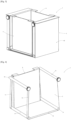
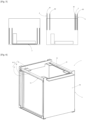
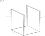
- a transfer box (1) is a rigid container in the form of a straight block, open at its upper end, consisting of a bottom wall (2) and four peripheral walls (3, 4, 5, 6), called respectively right side wall (3), left side wall (4), front wall (5) and rear wall (6), according to the representations in the figures, but it could be otherwise the transfer box (1) is a prism in the form of a polyhedron whose bottom wall (2) has a surface less than that of the face delimited by the upper ends of the peripheral walls (3, 4, 5, 6).
- the right side wall (3) and the left side wall (4) will be called side walls (3, 4).
- front wall (5) and the rear wall (6) are adjacent to the right side wall (3), and that the left side wall (4) is located opposite the right side wall (3).
- a deployed position of the bottom wall (2) partitions the transfer box (1) and is suitable for loading articles, while a withdrawn position of the bottom wall (2) frees the bottom of the transfer box (1) for depositing articles at the bottom of a carton, as explained in more detail in the remainder of the description.
- the bottom wall (2) comprises a first and a second longitudinal end, as explained in more detail in the remainder of the description, directed in the deployed position respectively in the direction of the right side wall (3) and in the direction of the left side wall (4).
- the aim of the invention is to place a set of articles simultaneously, without falling, advantageously in their initial storage or packaging position during order preparation, at the bottom of a box.
- Another complementary aim of the invention is to optimize the space occupied by the articles in a carton, in order to reduce the padding elements used to wedge the articles in the carton.
- the sizing of the cardboard used must advantageously correspond to the overall volume of the order, and the external dimensioning of the transfer box (1) must advantageously correspond to the internal space of the selected cardboard.
- the different transfer boxes (1) may have a dimension adapted to standardized carton sizes.
- the transfer case (1) can be independent and portable or integrated into a special machine, as described in more detail in the remainder of the description.
- the transfer box (1) is thus capable of being loaded with articles, of being inserted into a carton, of unloading the articles at the bottom of the carton, of being removed from the carton, of possibly placing wedging elements, of carrying out operations of closing and sealing the carton.
- the external dimensioning of the transfer box (1) should advantageously correspond to the internal dimensioning of the carton, so that the articles unloaded into the carton, after removal of the transfer box (1), advantageously have a minimum of free space with the walls of the carton.
- the transfer box (1) comprises a bottom wall (2) intended to adopt two positions, namely a deployed position, closing the bottom of the transfer box (1), and a withdrawn position, allowing the transfer box (1) to be opened from the bottom, in order to allow the release of the articles at the bottom of the box.
- the bottom wall (2) being intended to be removed from the space delimited by the lower ends of the peripheral walls (3, 4, 5, 6), when the transfer box (1) is located at the bottom of a carton, the size of the bottom wall (2) in its removed position must thus be reduced to a minimum, so that the articles deposited can occupy the greater part of the interior space of the carton.
- the transfer box (1) comprises drive means (10, 11), namely a removal means (10) and a return means (11), of the bottom wall (2).
- the transfer case (1) thus comprises a means (10) for removing the bottom wall (2) from a deployed position to a withdrawn position, and a means (11) for returning the bottom wall (2) from a folded position to a deployed position.
- the withdrawal means (10) and the return means (11) may be separate means or a single driving means (10, 11) of the bottom wall (2), as explained in more detail in the remainder of the description.
- the side walls (3, 4) each comprise a reservation space (7).
- the reservation space (7) of the left side wall (4) is intended for housing the drive means (10, 11) or a part of the drive means (10, 11), preferably the return means (11) or a part of the return means (11), as explained in more detail in the remainder of the description.
- the side walls (3, 4), namely the right side wall (3) and the left side wall (4), comprise two parallel plates (8), namely an inner plate (81) and an outer plate (82), delimiting the reservation space (7).
- the side walls (3, 4) are hollow walls consisting of two parallel plates (8) delimiting a reservation space (7).
- the side walls (3, 4) also comprise two transverse plates (9), bordering in width the reservation space (7), the two transverse plates (9) are arranged perpendicular to the internal plate (81) and the external plate (82).
- the side walls (3, 4) comprise a single plate (8), more precisely an internal plate (81), participating in delimiting the interior space of the transfer box (1), the reservation space (7) being adjacent to the plate (8), more precisely the reservation space (7) is located opposite the interior space of the transfer box (1) relative to the internal plate (81).
- the bottom wall (2) is a reinforced canvas or an assembly of articulated slats, such as a roller shutter.
- the withdrawal means (10) and the return means (11) are each located in a reservation space (7) delimited by the internal plate (81) and the external plate (82) of their respective side wall (3, 4).
- the withdrawal means (10) and the return means (11) are each located in a reservation space (7) bordered by the internal plate (81) of their respective side wall (3, 4).
- the withdrawal means (10) and the withdrawal means (11) are each located directly above a reservation space (7), namely located in the extension of the upper end of the side wall (3, 4) with which it is associated.
- the second longitudinal end of the bottom wall (2) is connected to the return means (11) by means of a connecting means (14).
- the connecting means (14) is materialized by two strips fixed to the corners of the first longitudinal end of the bottom wall (2), but it could be otherwise, the first connecting means (14) is materialized by cables, or even the connecting means (14) connected to the withdrawal means (10) is constituted by the extension of the bottom wall (2) directly attached to the withdrawal means (10).
- the connecting means (14) has a thickness less than the bottom wall (2).
- the connecting means (14) comprises at least one strip or cable.
- the withdrawal means (10) and the return means (11) may be rotational drive means (10, 11) or linear drive means (10, 11) of the bottom wall (2).
- the drive means (10, 11) can be manually or motorized.
- the withdrawal means (10) and the return means (11) are rotational drive means (10, 11).
- the drive means (10, 11) each comprise a drive roller (15) connected to a connecting means (14) secured to one of the longitudinal ends of the bottom wall (2).
- a drive roller (15) is located at the upper end of the reservation space (7), more precisely opposite or substantially opposite the upper ends of the internal plate (81) and the external plate (82) of a side wall (3, 4).
- a drive roller (15) is arranged parallel to the upper end of a side wall (3, 4).
- a drive roller (15) is secured to the two transverse plates (9), partitioning a side wall (3, 4) in width.
- the drive means (10, 11) advantageously comprise a guide roller (17) of the bottom wall (2) or a connecting means (14) of the return means (11), located at the lower end of the reservation space (7), but it could be otherwise the lower end of the side walls (3, 4) comprise a sliding coating having a low coefficient of friction.
- a guide roller (17) or a sliding covering facilitates the driving of the bottom wall (2) or the connecting means (14) of the return means (11) towards the reservation space (7), more precisely facilitates the cornering at the lower end of a side wall (3, 4).
- a guide roller (17) is arranged parallel to the lower end of a side wall (3, 4).
- a guide roller (17) is secured to the two transverse plates (9), partitioning a side wall (3, 4) in the thickness.
- the drive means (10, 11), namely the withdrawal means (10) and the return means (11), comprise an actuating means.
- the means for actuating the drive roller (15) may be any mechanical means allowing the rotation of the drive roller (15), for example a wheel, such as a toothed wheel (16), or a pinion, a flat wheel, a bevel gear or a magnet.
- a wheel such as a toothed wheel (16), or a pinion, a flat wheel, a bevel gear or a magnet.
- the actuating means comprises a toothed wheel (16) connected to the drive roller (15), the toothed wheel (16) projecting outside the transfer case (1), namely projecting outside the side wall (3, 4) to which it is secured.
- the transfer box (1) comprises a single drive means (10, 11) operating in the sliding directions of the bottom wall, namely playing the role of withdrawal means (10) and return means (11).
- the drive means (10, 11) comprises a slider (19), as an actuating means, slidably mounted on two parallel bars (18) fixed to the upper ends of the side walls (3, 4).
- the side walls (3, 4) have a height greater than those of the front wall (5) and the rear wall (6), such that the bars (18) are located above the upper ends of the front wall (5) and the rear wall (6), so as not to hinder the possible opening of the latter.
- the bars (18) are also located at the lateral ends of the side walls (3, 4) so as not to block a part of the upper end of the interior space of the transfer case (1).
- the connecting means (14) and the bottom wall (2) represent a closed loop.
- a strip runs along the lateral ends of a reservation space (7) and extends along the upper ends of the front wall (5) or the rear wall (6).
- the strips as connecting means (14) are housed in slides, not shown.
- the slider (19) is secured to the two strips forming the connecting means (14).
- the sliding of the slider (19) along the bars (18) causes the sliding of the connecting means (14), causing the sliding of the bottom wall (2) from a deployed position to a withdrawn position and vice versa, depending on the direction of manipulation of the slider (19).
- the drive means (10, 11) of the embodiment illustrated in [ Fig.6 ] comprises the connecting means (14), the slider (19) and the bars (18).
- the bottom wall (2) is directly connected at one of its ends to a withdrawal means (10) and connected at its other end to a connecting means (14) connected to a return means (11).
- the drive means (10, 11), namely the withdrawal means (10) and the return means (11), as well as the connecting means (14) and the bottom wall (2) are caused to slide in a reservation space (7) of a side wall (3, 4).
- the blades (20) as withdrawal means (10) and return means (11), are subject to actuating means, not shown, located in the special machine in which the transfer box (1) is integrated.
- each of the longitudinal ends of the bottom wall (2) is connected to a connecting means (14).
- the longitudinal end of a connecting means (14) is fixed to the upper end of the outer wall (82) inside the corresponding reservation space (7).
- a guide roller (17) is located at the upper end of a reservation space (7).
- a guide means (14) matches the upper end of the guide roller (17), extends along the reservation space (7) opposite the inner plate (81) and extends to the lower end of the inner plate (81).
- the connecting means (14) of the withdrawal means (10) located in the right side wall (3) is shorter than the connecting means (14) of the return means (11) located in the left side wall (4).
- the transfer box (1) according to the invention can be used in an automated or semi-automated manner, mobile or integrated into a special machine.
- a special machine not described in the application can actuate the transfer box (1), by opening and closing the front wall (5) or the rear wall (6), actuating the withdrawal means (10) and the return means (11) of the bottom wall (2), integrating a lift system for the transfer box (1) for its insertion and removal from a carton by the gripping means (13).
- the transfer box (1) is loaded with articles, manually by an operator, placed on a conveyor and taken care of by the special machine described briefly above.
- the transfer box (1) is previously taken over by the special machine, opening of the front wall (5) or the rear wall (6), automated loading of articles by the device described in the document FR 3 087 427 , to then be animated by the special machine introduced previously.
Landscapes
- Engineering & Computer Science (AREA)
- Mechanical Engineering (AREA)
- Details Of Rigid Or Semi-Rigid Containers (AREA)
- Cartons (AREA)
- Supplying Of Containers To The Packaging Station (AREA)
- Making Paper Articles (AREA)
Claims (10)
- Übergabebehälter (1) zum Übergeben von Artikeln in einen Karton, wobei der Übergabebehälter (1) in der Lage ist, in den Karton für die gleichzeitige Ablage von Artikeln ohne deren Herabfallen auf den Boden des Kartons eingesetzt zu werden, wobei der Übergabebehälter (1) umfasst: eine Bodenwand (2), die in der Lage ist, zwischen einer ausgefahrenen Position, in welcher sie den Boden des Übergabebehälters (1) schließt, und einer eingefahrenen Position verschoben zu werden, ein Antriebsmittel (10, 11) für die Bodenwand (2), zwei gegenüberliegende Seitenwände (3, 4), wobei die Bodenwand (2) in der Lage ist, durch Betätigung des Antriebsmittels (10, 11) entlang einer der Seitenwände (3, 4) für den Übergang von der ausgefahrenen Position in die eingefahrene Position verschoben zu werden.
- Übergabebehälter (1) nach Anspruch 1, dadurch gekennzeichnet, dass eine Seitenwand (3, 4) einen Reserveraum (7) umfasst, der durch eine innere Platte (81) und eine äußere Platte (82) begrenzt wird.
- Übergabebehälter (1) nach Anspruch 1 oder 2, dadurch gekennzeichnet, dass das Antriebsmittel (10, 11) ein Einfahrmittel (10) und ein Rückstellmittel (11) umfasst, die jeweils an einem Längsende der Bodenwand (2) gesichert sind.
- Übergabebehälter (1) nach einem der vorhergehenden Ansprüche, dadurch gekennzeichnet, dass das Antriebsmittel (10, 11) ein Verbindungsmittel (14) umfasst, das an einem Längsende der Bodenwand (2) gesichert ist.
- Übergabebehälter (1) nach einem der vorhergehenden Ansprüche, dadurch gekennzeichnet, dass er Mittel zum Betätigen des Antriebsmittels (10, 11) umfasst.
- Übergabebehälter (1) nach einem der vorhergehenden Ansprüche, dadurch gekennzeichnet, dass die Bodenwand (2) flexibel oder angelenkt ist.
- Übergabebehälter (1) nach einem der vorhergehenden Ansprüche, dadurch gekennzeichnet, dass er eine Vorderwand (5) und/oder eine Rückwand (6) benachbart zu einer Seitenwand (3, 4) umfasst, die in der Lage ist/sind, für das Einladen von Artikeln von der Seite her eine geschlossene und eine offene Position einzunehmen.
- Übergabebehälter (1) nach einem der vorhergehenden Ansprüche, dadurch gekennzeichnet, dass das Antriebsmittel (10, 11) ein Drehantriebsmittel oder ein Linearantriebsmittel der Bodenwand (2) ist.
- Übergabebehälter (1) nach einem der Ansprüche 1 bis 8, dadurch gekennzeichnet, dass das Antriebsmittel (10, 11) eine Antriebsrolle (15) umfasst, die mit einem Verbindungsmittel (14) verbunden ist, das an einem Längsende der Bodenwand (2) gesichert ist.
- Übergabebehälter (1) nach einem der Ansprüche 1 bis 8, dadurch gekennzeichnet, dass das Antriebsmittel (10, 11) ein Verbindungsmittel (14), das ein jedes der Längsenden der Bodenwand (2) verbindet, eine Stange (18), welche die oberen Enden der Seitenwände (3, 4) verbindet, und ein Gleitstück (19) umfasst, das auf der Stange (18) gleitend montiert ist, wobei das Gleitstück (19) an dem Verbindungsmittel (14) fixiert ist.
Applications Claiming Priority (2)
| Application Number | Priority Date | Filing Date | Title |
|---|---|---|---|
| FR2200104A FR3131736B1 (fr) | 2022-01-07 | 2022-01-07 | Boite de transfert d’articles dans un carton |
| PCT/EP2023/050219 WO2023131672A1 (fr) | 2022-01-07 | 2023-01-06 | Boite de transfert d'articles dans un carton |
Publications (3)
| Publication Number | Publication Date |
|---|---|
| EP4460463A1 EP4460463A1 (de) | 2024-11-13 |
| EP4460463B1 true EP4460463B1 (de) | 2025-07-02 |
| EP4460463C0 EP4460463C0 (de) | 2025-07-02 |
Family
ID=80787406
Family Applications (1)
| Application Number | Title | Priority Date | Filing Date |
|---|---|---|---|
| EP23700598.8A Active EP4460463B1 (de) | 2022-01-07 | 2023-01-06 | Übergabebehälter zum übergeben von artikeln in einen karton |
Country Status (4)
| Country | Link |
|---|---|
| US (1) | US20250108946A1 (de) |
| EP (1) | EP4460463B1 (de) |
| FR (1) | FR3131736B1 (de) |
| WO (1) | WO2023131672A1 (de) |
Families Citing this family (1)
| Publication number | Priority date | Publication date | Assignee | Title |
|---|---|---|---|---|
| CN117002850B (zh) * | 2023-10-07 | 2023-12-26 | 山西华澈天朗环保科技有限公司 | 一种土壤样本存储箱 |
Citations (1)
| Publication number | Priority date | Publication date | Assignee | Title |
|---|---|---|---|---|
| EP0227635A1 (de) * | 1985-12-23 | 1987-07-01 | Ing. Leibetseder Gesellschaft m.b.H. & Co. KG. | Vorrichtung zum Verpacken von in ihrer Grundform langestrecktzylindrischen Einheiten in Behältern |
Family Cites Families (12)
| Publication number | Priority date | Publication date | Assignee | Title |
|---|---|---|---|---|
| US4158421A (en) | 1978-01-30 | 1979-06-19 | Chi Hsu T | Foldable packing case |
| NL8003442A (nl) * | 1980-06-13 | 1982-01-04 | Derckx Henricus A J M | Inpakmachine. |
| US4805379A (en) * | 1987-10-06 | 1989-02-21 | Ferdinand Leibetseder | Process and apparatus for packaging stacks which consist of nested cuplike objects and have the basic shape of elongate cylinders |
| EP0610489B1 (de) | 1992-09-10 | 1997-07-30 | MAUSER-WERKE GmbH | Mehrweg-transportbehälter |
| FR2728542B1 (fr) | 1994-12-23 | 1997-03-28 | Radot Michel | Recipient a fond amovible |
| DE19719598C1 (de) * | 1997-05-09 | 1998-11-12 | Rovema Gmbh | Vorrichtung zum Einbringen von Verpackungen in einem Sammelbehälter |
| EP1847460B1 (de) * | 2006-04-18 | 2011-06-01 | Food Processing Systems BV | Füllbehälter |
| JP2009029291A (ja) * | 2007-07-27 | 2009-02-12 | Ricoh Co Ltd | 用紙補給・搬送補助装置 |
| FR2972722B1 (fr) * | 2011-03-14 | 2014-02-21 | Cinetic Sorting S P A | Tri direct de colis dans des conteneurs avec reduction du nombre de dommages |
| US9598203B2 (en) | 2013-12-24 | 2017-03-21 | Ookuma Electronic Co., Ltd. | Injection container storage box device and injection container picking system including the device |
| FR3087427B1 (fr) | 2018-10-19 | 2021-01-22 | Jacky Peterlini | Dispositif et procede de rassemblement et de dechargement d’articles |
| NO20190710A1 (en) * | 2019-06-11 | 2020-04-08 | Autostore Tech As | Storage system |
-
2022
- 2022-01-07 FR FR2200104A patent/FR3131736B1/fr active Active
-
2023
- 2023-01-06 US US18/725,881 patent/US20250108946A1/en active Pending
- 2023-01-06 WO PCT/EP2023/050219 patent/WO2023131672A1/fr not_active Ceased
- 2023-01-06 EP EP23700598.8A patent/EP4460463B1/de active Active
Patent Citations (1)
| Publication number | Priority date | Publication date | Assignee | Title |
|---|---|---|---|---|
| EP0227635A1 (de) * | 1985-12-23 | 1987-07-01 | Ing. Leibetseder Gesellschaft m.b.H. & Co. KG. | Vorrichtung zum Verpacken von in ihrer Grundform langestrecktzylindrischen Einheiten in Behältern |
Also Published As
| Publication number | Publication date |
|---|---|
| WO2023131672A1 (fr) | 2023-07-13 |
| EP4460463C0 (de) | 2025-07-02 |
| FR3131736B1 (fr) | 2024-02-23 |
| FR3131736A1 (fr) | 2023-07-14 |
| US20250108946A1 (en) | 2025-04-03 |
| EP4460463A1 (de) | 2024-11-13 |
Similar Documents
| Publication | Publication Date | Title |
|---|---|---|
| EP2543481A1 (de) | Griffsystem für Werkzeugwagen | |
| CH634973A5 (fr) | Boite a dejeuner pour enfants. | |
| CA2348711A1 (fr) | Dispositif automatique par gravite de verrouillage/deverrouillage du couvercle d'un bac et bac equipe d'un tel dispositif | |
| FR3017122A1 (fr) | Procede de chargement d'une poche souple 3d a emplir, un systeme de chargement et stockage de cette poche souple et dispositif de support associe. | |
| FR2536043A1 (fr) | Caisses de manutention empilables et emboitables du type a piliers de support sensiblement verticaux | |
| WO2023131672A1 (fr) | Boite de transfert d'articles dans un carton | |
| EP2624956B1 (de) | Reaktionsgefäss für ein automatisches chemisches oder biologisches analysegerät | |
| EP3263469A1 (de) | Maschine zum extrahieren, auffalten, füllen und schliessen einer faltschachtel | |
| FR2705089A1 (fr) | Récipient, notamment de forme parallélépipédique, pour au moins deux objets. | |
| FR2727671A1 (fr) | Boite articulee de transport de pieces detachees | |
| EP3526024B1 (de) | Verfahren und vorrichtung zum formen eines rohlings um eine spindel | |
| EP0124446B1 (de) | Werkzeugkoffer | |
| FR2983183A1 (fr) | Conteneur de collecte | |
| CA3114195A1 (fr) | Dispositif et procede de rassemblement et de dechargement d'articles | |
| FR3108098A1 (fr) | Installation de découpe et d’emballage de portions d’un produit alimentaire | |
| EP2409935A1 (de) | Flexibler Behälter | |
| EP0277880B1 (de) | Beförderungsvorrichtung, insbesondere für Selbstbedienungsläden | |
| EP1528012B1 (de) | Frachtbehälter für Luftfracht. | |
| EP0576311B1 (de) | Vorrichtung zum Sammeln von Postsachen | |
| FR2795709A1 (fr) | Module de stockage d'articles a elements de reception suspendus | |
| EP0255448B1 (de) | Vorrichtung zum Fördern von Kästen, insbesondere Kästen mit beweglichem Boden zum Umladen von Gegenständen auf gleichbleibendem Niveau | |
| FR2905361A1 (fr) | Emballage pour unite de volet roulant ou similaire. | |
| EP1559654A1 (de) | Behälter aus einem faltbaren Film | |
| FR3018438A1 (fr) | Dispositif de stockage et de distribution de tranches alimentaires | |
| FR2605130A1 (fr) | Procede et support d'affichage sur les chariots et chariots pourvus de ce support |
Legal Events
| Date | Code | Title | Description |
|---|---|---|---|
| STAA | Information on the status of an ep patent application or granted ep patent |
Free format text: STATUS: UNKNOWN |
|
| STAA | Information on the status of an ep patent application or granted ep patent |
Free format text: STATUS: THE INTERNATIONAL PUBLICATION HAS BEEN MADE |
|
| PUAI | Public reference made under article 153(3) epc to a published international application that has entered the european phase |
Free format text: ORIGINAL CODE: 0009012 |
|
| STAA | Information on the status of an ep patent application or granted ep patent |
Free format text: STATUS: REQUEST FOR EXAMINATION WAS MADE |
|
| 17P | Request for examination filed |
Effective date: 20240704 |
|
| AK | Designated contracting states |
Kind code of ref document: A1 Designated state(s): AL AT BE BG CH CY CZ DE DK EE ES FI FR GB GR HR HU IE IS IT LI LT LU LV MC ME MK MT NL NO PL PT RO RS SE SI SK SM TR |
|
| GRAP | Despatch of communication of intention to grant a patent |
Free format text: ORIGINAL CODE: EPIDOSNIGR1 |
|
| STAA | Information on the status of an ep patent application or granted ep patent |
Free format text: STATUS: GRANT OF PATENT IS INTENDED |
|
| DAV | Request for validation of the european patent (deleted) | ||
| DAX | Request for extension of the european patent (deleted) | ||
| INTG | Intention to grant announced |
Effective date: 20250219 |
|
| GRAS | Grant fee paid |
Free format text: ORIGINAL CODE: EPIDOSNIGR3 |
|
| GRAA | (expected) grant |
Free format text: ORIGINAL CODE: 0009210 |
|
| STAA | Information on the status of an ep patent application or granted ep patent |
Free format text: STATUS: THE PATENT HAS BEEN GRANTED |
|
| AK | Designated contracting states |
Kind code of ref document: B1 Designated state(s): AL AT BE BG CH CY CZ DE DK EE ES FI FR GB GR HR HU IE IS IT LI LT LU LV MC ME MK MT NL NO PL PT RO RS SE SI SK SM TR |
|
| REG | Reference to a national code |
Ref country code: GB Ref legal event code: FG4D Free format text: NOT ENGLISH |
|
| REG | Reference to a national code |
Ref country code: CH Ref legal event code: EP |
|
| REG | Reference to a national code |
Ref country code: DE Ref legal event code: R096 Ref document number: 602023004540 Country of ref document: DE |
|
| REG | Reference to a national code |
Ref country code: IE Ref legal event code: FG4D Free format text: LANGUAGE OF EP DOCUMENT: FRENCH |
|
| U01 | Request for unitary effect filed |
Effective date: 20250722 |
|
| U07 | Unitary effect registered |
Designated state(s): AT BE BG DE DK EE FI FR IT LT LU LV MT NL PT RO SE SI Effective date: 20250728 |
|
| PG25 | Lapsed in a contracting state [announced via postgrant information from national office to epo] |
Ref country code: IS Free format text: LAPSE BECAUSE OF FAILURE TO SUBMIT A TRANSLATION OF THE DESCRIPTION OR TO PAY THE FEE WITHIN THE PRESCRIBED TIME-LIMIT Effective date: 20251102 |
|
| PG25 | Lapsed in a contracting state [announced via postgrant information from national office to epo] |
Ref country code: NO Free format text: LAPSE BECAUSE OF FAILURE TO SUBMIT A TRANSLATION OF THE DESCRIPTION OR TO PAY THE FEE WITHIN THE PRESCRIBED TIME-LIMIT Effective date: 20251002 |
|
| U20 | Renewal fee for the european patent with unitary effect paid |
Year of fee payment: 4 Effective date: 20251205 |
|
| PG25 | Lapsed in a contracting state [announced via postgrant information from national office to epo] |
Ref country code: HR Free format text: LAPSE BECAUSE OF FAILURE TO SUBMIT A TRANSLATION OF THE DESCRIPTION OR TO PAY THE FEE WITHIN THE PRESCRIBED TIME-LIMIT Effective date: 20250702 |
|
| PG25 | Lapsed in a contracting state [announced via postgrant information from national office to epo] |
Ref country code: GR Free format text: LAPSE BECAUSE OF FAILURE TO SUBMIT A TRANSLATION OF THE DESCRIPTION OR TO PAY THE FEE WITHIN THE PRESCRIBED TIME-LIMIT Effective date: 20251003 |
|
| PG25 | Lapsed in a contracting state [announced via postgrant information from national office to epo] |
Ref country code: CZ Free format text: LAPSE BECAUSE OF FAILURE TO SUBMIT A TRANSLATION OF THE DESCRIPTION OR TO PAY THE FEE WITHIN THE PRESCRIBED TIME-LIMIT Effective date: 20250702 |
|
| PG25 | Lapsed in a contracting state [announced via postgrant information from national office to epo] |
Ref country code: PL Free format text: LAPSE BECAUSE OF FAILURE TO SUBMIT A TRANSLATION OF THE DESCRIPTION OR TO PAY THE FEE WITHIN THE PRESCRIBED TIME-LIMIT Effective date: 20250702 |
|
| PG25 | Lapsed in a contracting state [announced via postgrant information from national office to epo] |
Ref country code: RS Free format text: LAPSE BECAUSE OF FAILURE TO SUBMIT A TRANSLATION OF THE DESCRIPTION OR TO PAY THE FEE WITHIN THE PRESCRIBED TIME-LIMIT Effective date: 20251002 |
|
| PG25 | Lapsed in a contracting state [announced via postgrant information from national office to epo] |
Ref country code: ES Free format text: LAPSE BECAUSE OF FAILURE TO SUBMIT A TRANSLATION OF THE DESCRIPTION OR TO PAY THE FEE WITHIN THE PRESCRIBED TIME-LIMIT Effective date: 20250702 |
|
| PG25 | Lapsed in a contracting state [announced via postgrant information from national office to epo] |
Ref country code: SM Free format text: LAPSE BECAUSE OF FAILURE TO SUBMIT A TRANSLATION OF THE DESCRIPTION OR TO PAY THE FEE WITHIN THE PRESCRIBED TIME-LIMIT Effective date: 20250702 |
|
| PG25 | Lapsed in a contracting state [announced via postgrant information from national office to epo] |
Ref country code: SK Free format text: LAPSE BECAUSE OF FAILURE TO SUBMIT A TRANSLATION OF THE DESCRIPTION OR TO PAY THE FEE WITHIN THE PRESCRIBED TIME-LIMIT Effective date: 20250702 |
|
| PLBE | No opposition filed within time limit |
Free format text: ORIGINAL CODE: 0009261 |
|
| STAA | Information on the status of an ep patent application or granted ep patent |
Free format text: STATUS: NO OPPOSITION FILED WITHIN TIME LIMIT |