EP4459735A1 - Jelly-roll-elektrodenanordnung und sekundärbatterie damit - Google Patents
Jelly-roll-elektrodenanordnung und sekundärbatterie damit Download PDFInfo
- Publication number
- EP4459735A1 EP4459735A1 EP23877532.4A EP23877532A EP4459735A1 EP 4459735 A1 EP4459735 A1 EP 4459735A1 EP 23877532 A EP23877532 A EP 23877532A EP 4459735 A1 EP4459735 A1 EP 4459735A1
- Authority
- EP
- European Patent Office
- Prior art keywords
- electrode
- current collector
- longitudinal end
- jelly
- end portion
- Prior art date
- Legal status (The legal status is an assumption and is not a legal conclusion. Google has not performed a legal analysis and makes no representation as to the accuracy of the status listed.)
- Pending
Links
Images

Classifications
-
- H—ELECTRICITY
- H01—ELECTRIC ELEMENTS
- H01M—PROCESSES OR MEANS, e.g. BATTERIES, FOR THE DIRECT CONVERSION OF CHEMICAL ENERGY INTO ELECTRICAL ENERGY
- H01M10/00—Secondary cells; Manufacture thereof
- H01M10/05—Accumulators with non-aqueous electrolyte
- H01M10/058—Construction or manufacture
- H01M10/0587—Construction or manufacture of accumulators having only wound construction elements, i.e. wound positive electrodes, wound negative electrodes and wound separators
-
- H—ELECTRICITY
- H01—ELECTRIC ELEMENTS
- H01M—PROCESSES OR MEANS, e.g. BATTERIES, FOR THE DIRECT CONVERSION OF CHEMICAL ENERGY INTO ELECTRICAL ENERGY
- H01M10/00—Secondary cells; Manufacture thereof
- H01M10/04—Construction or manufacture in general
- H01M10/0431—Cells with wound or folded electrodes
-
- H—ELECTRICITY
- H01—ELECTRIC ELEMENTS
- H01M—PROCESSES OR MEANS, e.g. BATTERIES, FOR THE DIRECT CONVERSION OF CHEMICAL ENERGY INTO ELECTRICAL ENERGY
- H01M10/00—Secondary cells; Manufacture thereof
- H01M10/04—Construction or manufacture in general
-
- H—ELECTRICITY
- H01—ELECTRIC ELEMENTS
- H01M—PROCESSES OR MEANS, e.g. BATTERIES, FOR THE DIRECT CONVERSION OF CHEMICAL ENERGY INTO ELECTRICAL ENERGY
- H01M10/00—Secondary cells; Manufacture thereof
- H01M10/42—Methods or arrangements for servicing or maintenance of secondary cells or secondary half-cells
- H01M10/4235—Safety or regulating additives or arrangements in electrodes, separators or electrolyte
-
- H—ELECTRICITY
- H01—ELECTRIC ELEMENTS
- H01M—PROCESSES OR MEANS, e.g. BATTERIES, FOR THE DIRECT CONVERSION OF CHEMICAL ENERGY INTO ELECTRICAL ENERGY
- H01M4/00—Electrodes
- H01M4/02—Electrodes composed of, or comprising, active material
- H01M4/64—Carriers or collectors
- H01M4/70—Carriers or collectors characterised by shape or form
-
- H—ELECTRICITY
- H01—ELECTRIC ELEMENTS
- H01M—PROCESSES OR MEANS, e.g. BATTERIES, FOR THE DIRECT CONVERSION OF CHEMICAL ENERGY INTO ELECTRICAL ENERGY
- H01M50/00—Constructional details or processes of manufacture of the non-active parts of electrochemical cells other than fuel cells, e.g. hybrid cells
- H01M50/50—Current conducting connections for cells or batteries
- H01M50/531—Electrode connections inside a battery casing
- H01M50/538—Connection of several leads or tabs of wound or folded electrode stacks
-
- H—ELECTRICITY
- H01—ELECTRIC ELEMENTS
- H01M—PROCESSES OR MEANS, e.g. BATTERIES, FOR THE DIRECT CONVERSION OF CHEMICAL ENERGY INTO ELECTRICAL ENERGY
- H01M10/00—Secondary cells; Manufacture thereof
- H01M10/05—Accumulators with non-aqueous electrolyte
- H01M10/052—Li-accumulators
-
- H—ELECTRICITY
- H01—ELECTRIC ELEMENTS
- H01M—PROCESSES OR MEANS, e.g. BATTERIES, FOR THE DIRECT CONVERSION OF CHEMICAL ENERGY INTO ELECTRICAL ENERGY
- H01M50/00—Constructional details or processes of manufacture of the non-active parts of electrochemical cells other than fuel cells, e.g. hybrid cells
- H01M50/10—Primary casings; Jackets or wrappings
- H01M50/102—Primary casings; Jackets or wrappings characterised by their shape or physical structure
- H01M50/107—Primary casings; Jackets or wrappings characterised by their shape or physical structure having curved cross-section, e.g. round or elliptic
-
- Y—GENERAL TAGGING OF NEW TECHNOLOGICAL DEVELOPMENTS; GENERAL TAGGING OF CROSS-SECTIONAL TECHNOLOGIES SPANNING OVER SEVERAL SECTIONS OF THE IPC; TECHNICAL SUBJECTS COVERED BY FORMER USPC CROSS-REFERENCE ART COLLECTIONS [XRACs] AND DIGESTS
- Y02—TECHNOLOGIES OR APPLICATIONS FOR MITIGATION OR ADAPTATION AGAINST CLIMATE CHANGE
- Y02E—REDUCTION OF GREENHOUSE GAS [GHG] EMISSIONS, RELATED TO ENERGY GENERATION, TRANSMISSION OR DISTRIBUTION
- Y02E60/00—Enabling technologies; Technologies with a potential or indirect contribution to GHG emissions mitigation
- Y02E60/10—Energy storage using batteries
-
- Y—GENERAL TAGGING OF NEW TECHNOLOGICAL DEVELOPMENTS; GENERAL TAGGING OF CROSS-SECTIONAL TECHNOLOGIES SPANNING OVER SEVERAL SECTIONS OF THE IPC; TECHNICAL SUBJECTS COVERED BY FORMER USPC CROSS-REFERENCE ART COLLECTIONS [XRACs] AND DIGESTS
- Y02—TECHNOLOGIES OR APPLICATIONS FOR MITIGATION OR ADAPTATION AGAINST CLIMATE CHANGE
- Y02P—CLIMATE CHANGE MITIGATION TECHNOLOGIES IN THE PRODUCTION OR PROCESSING OF GOODS
- Y02P70/00—Climate change mitigation technologies in the production process for final industrial or consumer products
- Y02P70/50—Manufacturing or production processes characterised by the final manufactured product
Definitions
- the present invention relates to a jelly-roll type electrode assembly and a secondary battery including the same, and more particularly, to a jelly-roll type electrode assembly having an outer circumference tab structure and a cylindrical secondary battery including the same.
- the present application claims priority to and the benefit of Korean Patent Application No. 10-2022-0130820 filed with the Korean Intellectual Property Office on October 12, 2022 , the entire contents of which are incorporated herein by reference.
- a jelly-roll type electrode assembly is manufactured by rolling a long electrode having a prescribed width into a roll form.
- a cylindrical battery manufactured by inserting such a jelly-roll type electrode assembly into a battery case is subjected to repeating contraction/expansion of the electrode during charging and discharging, and stress due to a step is formed according to a structure of the jelly-roll.
- the outermost negative electrode covers an end portion of a positive electrode, and a space next to the free edge of the positive electrode is left empty due to a thickness of the positive electrode.
- the step due to the thickness of the positive electrode forms stress in the negative electrode, and the stress may be concentrated on a surface opposite to a surface of the negative electrode facing the positive electrode during charging and discharging, thereby causing an outer crack in the negative electrode.
- the present invention has been made in an effort to provide a jelly-roll type electrode assembly whose design has been changed, and a secondary battery including the same.
- An exemplary embodiment of the present invention provides a jelly-roll type electrode assembly in which a first electrode, a separator, and a second electrode are stacked and wound, wherein the second electrode includes a second electrode current collector; and a second electrode active material layer provided on at least one surface of the second electrode current collector, wherein the first electrode includes a first electrode current collector; a first electrode active material layer provided on at least one surface of the first electrode current collector; a disconnection prevention portion provided on a surface of the first electrode current collector opposite to a surface facing a longitudinal end portion of the second electrode; and a weld portion electrically connecting the first electrode current collector and the disconnection prevention portion, wherein the disconnection prevention portion includes the weld portion electrically connected to the first electrode current collector, and wherein both longitudinal end portions of the disconnection prevention portion do not coincide with the longitudinal end portion of the second electrode.
- Another exemplary embodiment of the present invention provides a secondary battery including the jelly-roll type electrode assembly described above; and a battery case for accommodating the electrode assembly.
- the jelly-roll type electrode assembly and the secondary battery including the same includes the disconnection prevention portion, whereby it is possible to prevent crack and deformation of the electrode assembly due to stress concentration on the outermost negative electrode.
- the disconnection prevention portion is electrically connected to the electrode current collector via the weld portion to provide an additional conductive passage, so it is possible to suppress an increase in resistance and improve battery stability even in the event of disconnection.
- the jelly-roll type electrode assembly and the secondary battery including the same can prevent local problems such as reduction in roundness and lithium precipitation due to formation of additional steps by adjusting positions of the disconnection prevention portion and the weld portion, and can minimize occurrence of additional cracks and deformation of the electrode assembly due to formation of fixed points.
- a member when referred to as being "on" another member, the member can be in direct contact with another member or an intervening member may also be present.
- An exemplary embodiment of the present invention provides a jelly-roll type electrode assembly in which a first electrode, a separator, and a second electrode are stacked and wound, wherein the second electrode includes a second electrode current collector; and a second electrode active material layer provided on at least one surface of the second electrode current collector, wherein the first electrode includes a first electrode current collector; a first electrode active material layer provided on at least one surface of the first electrode current collector; a disconnection prevention portion provided on a surface of the first electrode current collector opposite to a surface facing a longitudinal end portion of the second electrode; and a weld portion electrically connecting the first electrode current collector and the disconnection prevention portion, and wherein both longitudinal end portions of the disconnection prevention portion do not coincide with the longitudinal end portion of the second electrode.
- the jelly-roll type electrode assembly and the secondary battery including the same includes the disconnection prevention portion, whereby it is possible to prevent crack and deformation of the electrode assembly due to stress concentration on the outermost negative electrode.
- the disconnection prevention portion is electrically connected to the electrode current collector via the weld portion to provide an additional conductive passage, it is possible to suppress an increase in resistance and improve battery stability even in the event of disconnection.
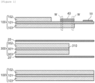
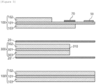
- FIGS. 1 and 2 show a jelly-roll type electrode assembly including a disconnection prevention portion according to an exemplary embodiment of the present invention.
- FIG. 1 is a view showing an exemplary embodiment including a weld portion including a first electrode active material layer on a surface of a first electrode current collector facing a longitudinal end portion of a second electrode
- FIG. 2 is a view showing an exemplary embodiment including a weld portion that does not include the first electrode active material layer on the surface of the first electrode current collector facing the longitudinal end portion of the second electrode.
- a jelly-roll type electrode assembly is a jelly-roll type electrode assembly in which a first electrode 100, 100', a separator 20, 20', and a second electrode 300 are stacked and wound, wherein the second electrode 300 may include a second electrode current collector 301; and a second electrode active material layer 302, 303 provided on at least one surface of the second electrode current collector 301, wherein the first electrode 100 may include a first electrode current collector 101; a first electrode active material layer 102, 103 provided on at least one surface of the first electrode current collector 101; a disconnection prevention portion 40 provided on a surface of the first electrode current collector 101 opposite to a surface facing a longitudinal end portion 310 of the second electrode; and a weld portion W electrically connecting the first electrode current collector 101 and the disconnection prevention portion 40, wherein the disconnection prevention portion 40 may include the weld portion W electrically connected to the first electrode current collector 101, and wherein both longitudinal end portions of the disconnection
- the 'longitudinal direction' may refer to a longitudinal direction of the first electrode, the separator, the second electrode, and the electrode assembly in which they are stacked before winding, i.e., a direction perpendicular to a winding axis direction of the electrode assembly after winding, and the meaning of 'longitudinal end portions coincide' may include a case where each end portion is located at exactly the same position based on a cross section perpendicular to the longitudinal direction of the electrode assembly, and a case where errors in processing and measurement exist.
- the disconnection prevention portion may be made of a conductive material.
- the disconnection prevention portion may be made of any one selected from copper, stainless steel, aluminum, nickel, titanium, and fired carbon. More specifically, the disconnection prevention portion may be made of copper, stainless steel, or aluminum, and may be surface-treated with carbon, nickel, titanium, silver, or the like. For example, transition metals that adsorb carbon well, such as copper and nickel, may be used.
- the disconnection prevention portion is made of the conductive material described above, the disconnection prevention portion is electrically connected to the electrode current collector via the weld portion to provide an additional conductive passage, whereby it is possible to suppress an increase in resistance and improve battery stability even in the event of disconnection of the electrode current collector.
- the disconnection prevention portion may be made of the same material as that of the first electrode current collector.
- the first electrode current collector may be conductive without inducing chemical changes in the battery, as described below, and the disconnection prevention portion may be made of the same material as that of the first electrode current collector.
- the first electrode current collector and the disconnection prevention portion may each be a copper foil (Cu foil). A point where the first electrode current collector and the disconnection prevention portion are welded may act as a fixing point.
- the first electrode current collector and the disconnection prevention portion are made of different types of materials, a portion fixed by the fixing point and a portion not fixed by the fixing point may undergo different degrees of deformation or volume change during charging and discharging, and distortion of the first electrode current collector may occur due to partial deformation of the electrode assembly.
- the disconnection prevention portion made of the same material as that of the first electrode current collector is used, so the elongation rates of the first electrode current collector and the disconnection prevention portion are similar, so the degrees of deformation or volume change during charging and discharging may be similar. Therefore, the occurrence of distortion of the electrode current collector due to the fixing point can be reduced and problems such as corrosion that may occur when welding different materials can be prevented.
- the material used for the first electrode current collector can be used, it can be easy to provide the disconnection prevention portion without additional production facilities.
- both longitudinal end portions of the disconnection prevention portion may not coincide with a longitudinal end portion of the second electrode.
- the longitudinal end portion of the second electrode may be located between both longitudinal end portions of the disconnection prevention portion.
- both longitudinal end portions of the disconnection prevention portion may be spaced apart from the longitudinal end portion of the second electrode by 2 mm or more and 10 mm or less. Specifically, both longitudinal end portions of the disconnection prevention portion may be spaced apart from the longitudinal end portion of the second electrode by 3 mm or more or 5 mm or more and 9 mm or less or 7 mm or less.
- both longitudinal end portions of the disconnection prevention portion have a separation distance within the above-described range from the longitudinal end portion of the second electrode, a region of the first electrode current collector corresponding to the longitudinal end portion of the second electrode, particularly a surface opposite to a surface facing the longitudinal end portion of the second electrode can be efficiently complemented, and crack and deformation due to stress concentration on the outermost first electrode can be prevented.
- a region required to weld the disconnection prevention portion can be sufficiently secured.
- the disconnection prevention portion may be provided on a surface of the first electrode current collector opposite to a surface facing the longitudinal end portion of the second electrode. Specifically, the disconnection prevention portion may be provided spaced apart from a longitudinal end portion of the first electrode active material layer on a surface of the first electrode current collector opposite to a surface facing the longitudinal end portion of the second electrode. That is, the disconnection prevention portion may be provided on a first electrode uncoated portion of the first electrode current collector where the first electrode active material layer is not provided.
- the disconnection prevention portion When the disconnection prevention portion is provided on the surface opposite to the surface facing the longitudinal end portion of the second electrode, a problem of additional step formation caused by a thickness of the disconnection prevention portion can be prevented, and asymmetric formation of the electrode assembly can be minimized to improve roundness. Accordingly, damage to a lower end portion of the electrode assembly can be minimized during a post-process of inserting the electrode assembly into a battery case. Furthermore, occurrence of local problems such as damage to the electrode assembly due to an increase in pressure in a specific part when a volume of the electrode assembly changes due to a charging and discharging cycle, a side reaction due to lack of an electrolyte and lithium precipitation can be reduced.
- the roundness may refer to a value obtained by subtracting the minimum value of the outer diameter from the maximum value of the outer diameter of the jelly-roll type electrode assembly.
- the first electrode may further include a first electrode tab provided at a longitudinal end portion of the first electrode, and the disconnection prevention portion may be formed between the longitudinal end portion of the first electrode active material layer and the first electrode tab.
- the first electrode tab may be welded and electrically connected to a battery case for accommodating the electrode assembly on the outermost side of the jelly-roll type electrode assembly, and may serve as a fixing point for the electrode assembly during welding.
- the electrode assembly further includes the first electrode tab on the outermost side, the disconnection prevention portion is provided between the longitudinal end portion of the first electrode active material layer and the first electrode tab, thereby reducing occurrence of additional distortion of the electrode current collector due to a plurality of fixing points.
- the first electrode tab may be provided on the surface of the first electrode current collector opposite to the surface facing the longitudinal end portion of the second electrode. That is, the first electrode tab may be provided on the same surface as the disconnection prevention portion provided on the first electrode current collector, and formation of steps due to the thicknesses of the first electrode tab and the disconnection prevention portion may be minimized.
- a problem of additional step formation that may be caused when the first electrode tab is provided on the surface of the first electrode facing the longitudinal end portion of the second electrode can be prevented, and asymmetric formation of the electrode assembly can be minimized to improve roundness. Accordingly, damage to a lower end portion of the electrode assembly can be minimized during a post-process of inserting the electrode assembly into a battery case.
- occurrence of local problems such as damage to the electrode assembly due to an increase in pressure in a specific part when a volume of the electrode assembly changes due to a charging and discharging cycle, a side reaction due to lack of an electrolyte and lithium precipitation can be reduced.
- welding between the first electrode tab located at the outermost side of the electrode assembly and the battery case may be more easily performed, and the electrical connection may be more stable.
- FIG. 3 is an image of a jelly-roll type electrode assembly implemented according to an exemplary embodiment of the present invention.
- a length, in a winding axis direction, of the disconnection prevention portion may be 50% or more and 100% or less based on a length, in the winding axis direction, of the first electrode current collector. Specifically, referring to FIG.
- a length Lh, in a winding axis direction, of the disconnection prevention portion may be 55% or more, 60% or more or 65% or more based on 100% of a length, in the winding axis direction, of the first electrode current collector, and the length Lh, in the winding axis direction, of the disconnection prevention portion may be 95% or less, 90% or less or 85% or less based on 100% of the length, in the winding axis direction, of the first electrode current collector.
- a region of the first electrode current collector corresponding to the longitudinal end portion of the second electrode, particularly a surface opposite to a surface facing the longitudinal end portion of the second electrode can be efficiently complemented, and the occurrence of problems such as cracks during charging and discharging can be reduced to ensure the battery stability.
- the length, in the longitudinal direction, of the disconnection prevention portion may be 25 mm or longer and 400 mm or less.
- the length L2, in the longitudinal direction, of the disconnection prevention portion may be 30 mm or longer, 35 mm or longer, or 40 mm or longer, and the length L2, in the longitudinal direction, of the disconnection prevention portion may be 395 mm or less, 390 mm or less, or 385 mm or less.
- a region of the first electrode current collector corresponding to the longitudinal end portion of the second electrode, particularly a surface opposite to a surface facing the longitudinal end portion of the second electrode can be efficiently complemented, and the occurrence of problems such as cracks during charging and discharging can be reduced to ensure the battery stability.
- the separation distance between one longitudinal end portion of the disconnection prevention portion and a longitudinal end portion of the first electrode active material layer provided on one surface of the first electrode current collector may be 5 mm or longer and 100 mm or less. Specifically, referring to FIG.
- the separation distance L1 between one longitudinal end portion of the disconnection prevention portion 40 and a longitudinal end portion of the first electrode active material layer 102 provided on one surface of the first electrode current collector 101 may be 10 mm or longer, 15 mm or longer, or 20 mm or longer, and the separation distance L1 between one longitudinal end portion of the disconnection prevention portion 40 and a longitudinal end portion of the first electrode active material layer 102 provided on one surface of the first electrode current collector 101 may be 95 mm or less, 90 mm or less, or 85 mm or less.
- the separation distance between one longitudinal end portion of the disconnection prevention portion and the first electrode tab provided on one surface of the first electrode current collector may be 5 mm or longer and 100 mm or less.
- the separation distance L3 between one longitudinal end portion of the disconnection prevention portion 40 and the first electrode tab 50 provided on one surface of the first electrode current collector 101 may be 10 mm or longer, 15 mm or longer, or 20 mm or longer, and the separation distance L3 between one longitudinal end portion of the disconnection prevention portion 40 and the first electrode tab 50 provided on one surface of the first electrode current collector 101 may be 95 mm or less, 90 mm or less, or 85 mm or less.
- the separation distance L3 between one longitudinal end portion of the disconnection prevention portion and the first electrode tab provided on one surface of the first electrode current collector satisfies the range described above, the formation of an additional step in relation to the first electrode tab can be minimized while providing the disconnection prevention portion in the jelly-roll type electrode assembly, and an increase in resistance due to additional welding of the first electrode tab and the disconnection prevention portion during welding can be prevented.
- the first electrode may include a weld portion electrically connecting the first electrode current collector and the disconnection prevention portion.
- the weld portion W is a region where welding is performed in order to electrically connect the first electrode current collector 101 and the disconnection prevention portion 40, and may refer to a region including a cross section perpendicular to the longitudinal direction of the first electrode.
- the weld portion may include the disconnection prevention portion and the first electrode current collector; or the disconnection prevention portion, the first electrode active material layer, and the first electrode current collector.
- the weld portion may be formed in a linear or spot shape depending on a welding method described below, and may have a predetermined length in the winding axis direction, a length in the longitudinal direction, and an area required for welding.
- the weld portion may be formed at each of both longitudinal end portions of the disconnection prevention portion, and may be formed at a predetermined distance apart from each of both end portions of the disconnection prevention portion.
- a separation distance L4, L8 between the weld portion and each of both longitudinal end portions of the disconnection prevention portion may be 2 mm or less.
- the weld portion may not overlap with the longitudinal end portion of the second electrode. Specifically, based on the longitudinal direction of the first electrode, the weld portion may be spaced apart from the longitudinal end portion of the second electrode by 1 mm or more and 8 mm or less. More specifically, the weld portion may be spaced apart from the longitudinal end portion of the second electrode by 1 mm or more or 3 mm or more, and 8 mm or less or 6 mm or less.
- the weld portion has a separation distance within the above-described range from the longitudinal end portion of the second electrode, a region required to weld the disconnection prevention portion can be sufficiently secured, and a problem of additional step formation that may be caused when the weld portion overlaps the longitudinal end portion of the second electrode can be prevented.
- the weld portion may be formed in plural. Specifically, the weld portion may be formed in plural in order to minimize asymmetry due to the fixing point on the first electrode current collector.
- the first electrode current collector may undergo a change of volume due to repeating contraction and expansion, and the weld portion may act as a fixing point, causing distortion of the first electrode current collector.
- the weld portion is formed in plural, it is possible to prevent the occurrence of a crack due to the formation of fixing point at a specific position and to secure a sufficient cross-sectional area of a conductive passage even in the event of disconnection, thereby preventing deterioration in electrochemical properties, such as a decrease in cycle efficiency due to an increase in resistance.
- the weld portion may be formed in plural, and the plurality of weld portions may be formed to be symmetrical to each other.
- the plurality of weld portions may be formed to be symmetrical with respect to a longitudinal center of the disconnection prevention portion. That is, the separation distances L4, L8 between the weld portions and both longitudinal end portions of the disconnection prevention portion may be the same.
- the longitudinal center of the disconnection prevention portion may refer to a point that is 1/2 of a length, in the longitudinal direction, of the disconnection prevention portion.
- the plurality of weld portions may be formed to be symmetrical with respect to a center, in the winding axis direction, of the disconnection prevention portion.
- the center, in the winding axis direction, of the disconnection prevention portion may refer to a point that is 1/2 of a length, in the winding axis direction, of the disconnection prevention portion.
- the weld portion may be formed in plural, and the longitudinal end portion of the second electrode may be located between the plurality of weld portions.
- the weld portion may be formed in plurality at a distance apart from the longitudinal end portion of the second electrode by 1 mm or more and 8 mm or less so that the longitudinal end portion of the second electrode is located between the plurality of weld portions.
- the plurality of weld portions may be formed to be symmetrical with respect to the center, in the winding axis direction, of the first electrode current collector.
- the center, in the winding axis direction, of the first electrode current collector may refer to a point that is 1/2 of a length, in the winding axis direction, of the first electrode current collector.
- the welding portion may include the first electrode active material layer provided on the surface of the first electrode current collector facing the longitudinal end portion of the second electrode.
- the first electrode current collector 101 may have the first electrode active material layer 103 on the surface facing the longitudinal end portion 310 of the second electrode, and the weld portion W may be formed in one longitudinal region of the first electrode including the disconnection prevention portion 40, the first electrode current collector 101, and the first electrode active material layer 103.
- the weld portion W may be suitable for ultrasonic welding or arc welding.
- ultrasonic welding is a method of joining by applying high-frequency lateral vibration to a base material to diffuse atoms in a contact part by vibration energy, and can prevent thermal damage to the first electrode during welding because it does not involve heating.
- arc welding is a processing method of joining workpieces by melting the base material or material using arc discharge, and melts the disconnection prevention portion provided on one surface and also welds the first electrode current collector below, making it easy to perform single-side welding.
- the weld portion may not include the first electrode active material layer on the surface of the first electrode current collector facing the longitudinal end portion of the second electrode.
- the first electrode current collector 101 may include a single-side coated portion having the first electrode active material layer 103 and an uncoated portion not provided with the first electrode active material layer on the surface facing the longitudinal end portion 310 of the second electrode, and the weld portion W may be formed in one region, in the longitudinal direction, of the first electrode including the disconnection prevention portion 40 and the uncoated portion of the first electrode current collector 101.
- the weld portion may further include an uncoated portion for welding on the opposite surface to the surface of the first electrode current collector provided with the disconnection prevention portion.
- the weld portion W does not include the first electrode active material layer 103
- the weld portion may be suitable for laser welding or resistance welding.
- laser welding is a method of welding by heating a contact part with oxyacetylene or propane flame and then applying pressure, and a YAG laser or CO 2 laser may be used.
- resistance welding is a processing method of joining two materials through pressure without melting the materials. The resistance welding is a processing method that can obtain a strong joint by applying external pressure while heating materials through a high-current electric circuit. Since facilities that are usually used for tab welding can be used, additional facilities are not required, so economic efficiency can be ensured.
- the surface of the first electrode current collector facing the longitudinal end portion of the second electrode may be provided with a first electrode active material layer.
- the first electrode current collector 101 may include a predetermined length of a single-side coated portion provided with the first electrode active material layer 103 on the surface facing the longitudinal end portion 310 of the second electrode.
- a length, in the longitudinal direction, of the single-side coated portion may be 20 mm or longer and 200 mm or less.
- a length L6, in the longitudinal direction, of the single-side coated portion provided on the surface of the first electrode current collector 101 facing the longitudinal end portion 310 of the second electrode may be 25 mm or longer, 30 mm or longer, or 35 mm or longer, and the length L6, in the longitudinal direction, of the single-side coated portion may be 195 mm or less, 190 mm or less, or 185 mm or less.
- the internal space of the battery case may refer to a volume obtained by excluding a volume of the jelly-roll type electrode assembly accommodated in the battery case and a volume of the electrolyte solution from an internal volume of the battery case.
- the weld portion may be formed at a predetermined distance apart from each of both longitudinal end portions of the single-side coated portion.
- separation distances L5, L7 between the weld portions and both longitudinal end portions of the single-side coated portion may be 2 mm or longer.
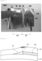
- FIG. 4 schematically shows a step portion of a jelly-roll type electrode assembly according to an exemplary embodiment of the present invention
- FIG. 5 shows the jelly-roll type electrode assembly as a reference drawing.
- the jelly-roll type electrode assembly may include a step portion 60, which is an empty space formed in a region where the first electrode 100 covers the longitudinal end portion 310 of the second electrode 300, and the disconnection prevention portion may be provided on a surface opposite to a surface facing the step portion 60, i.e., a surface of the first electrode current collector opposite to a surface facing the longitudinal end portion of the second electrode.
- the first electrode 100 located on the outermost side may extend longer than the longitudinal end portion 310 of the second electrode 300 and may be additionally wound to the outside of the electrode assembly, the step portion 60, which is a region where a step due to a thickness of the second electrode is formed, may be formed next to the longitudinal end portion 310 of the second electrode 300, and the disconnection prevention portion may be provided on a surface of the first electrode 100 opposite to a surface facing the step portion 60.
- the jelly-roll type electrode assembly may form a stacked structure of the first electrode/separator/second electrode/separator/first electrode in a wound state.
- a length of the second electrode may be shorter than those of the remaining layers, and a region where a stacked structure of the first electrode/separator/empty space/separator/first electrode is formed, i.e., the step portion 60 may be present on the outermost side of the wound electrode assembly.
- a disconnection prevention tape 70 may be attached on the opposite surface to the surface facing the step portion 60. However, if the disconnection prevention tape 70 does not have a sufficient thickness, the effect of preventing electrode cracks may be insufficient, and the effect of improving the problems such as an increase in resistance and overcharge stability may deteriorate in the event of disconnection.
- the electrode assembly according to the present invention is provided with the disconnection prevention portion 40 on the surface of the first electrode 100 opposite to the surface facing the step portion 60, and the disconnection prevention portion 40 includes the weld portion W electrically connected to the first electrode current collector 101, whereby cracks and deformation of the electrode assembly due to stress concentration on the outermost negative electrode can be prevented and an additional conductive passage is provided, so the increase in resistance can be suppressed and the battery stability can be improved, even in the event of disconnection.
- the first electrode may be a negative electrode
- the second electrode may be a positive electrode
- the first electrode which is the outermost layer of the electrode assembly
- the electrode assembly may have a negative electrode-outermost structure where a negative electrode/a separator/a positive electrode/a separator are wound.
- the jelly-roll type electrode assembly may have an outer circumferential tab structure where the negative electrode is exposed on the outermost side.
- the first electrode may include a first electrode current collector and a first electrode active material layer provided on the first electrode current collector.
- the first electrode may include a first electrode current collector and a first electrode active material layer formed on one surface or both surfaces of the first electrode current collector and including a first electrode active material.
- the first electrode active material layer may be formed on a first electrode coated portion of the first electrode current collector, and a surface not provided with the first electrode active material layer may be expressed as a first electrode uncoated portion.
- the first electrode current collector may include a first electrode coated portion where the first electrode active material layer is formed and a first electrode uncoated portion where the first electrode active material layer is not formed, and may include a first electrode tab on the first electrode uncoated portion.
- the first electrode current collector may include a first electrode uncoated portion and a first electrode tab formed on the first electrode uncoated portion.
- the manufactured electrode assembly may include one or more first electrode tabs.
- the first electrode active material layer may include a first electrode active material including one or more selected from the group consisting of a silicon-based material and a carbon-based material.
- the first electrode active material layer may further include a first electrode conductive material and a first electrode binder, and for the first electrode active material, the first electrode conductive material, and the first electrode binder, materials that are used as a negative electrode active material, a negative electrode conductive material, and a negative electrode binder in the art may be used without limitation.
- the first electrode current collector is not particularly limited as long as it has conductivity without inducing a chemical change in the battery.
- the first electrode current collector copper, stainless steel, aluminum, nickel, titanium, fired carbon, aluminum or stainless steel each surface-treated with carbon, nickel, titanium, silver, or the like, or the like may be used.
- transition metals that adsorb carbon well, such as copper and nickel may be used for the first electrode current collector.
- a thickness of the first electrode current collector may be 8 um or greater and 180 um or less. However, the thickness of the first electrode current collector is not limited thereto.
- the first electrode binder may include at least one selected from the group consisting of polyvinylidenefluoride-hexafluoropropylene copolymer (PVDF-co-HFP), polyvinylidenefluoride, polyacrylonitrile, polymethylmethacrylate, polyvinyl alcohol, carboxymethylcellulose (CMC), starch, hydroxypropylcellulose, regenerated cellulose, polyvinylpyrrolidone, tetrafluoroethylene, polyethylene, polypropylene, polyacrylic acid, ethylene-propylene-diene monomer (EPDM), sulfonated EPDM, styrene butadiene rubber (SBR), fluoro rubber, poly acrylic acid, and the above-mentioned materials in which a hydrogen is substituted with Li, Na, Ca, etc., and may also include various copolymers thereof.
- PVDF-co-HFP polyvinylidenefluoride-hexafluoropropylene copolymer
- the first electrode conductive material is not particularly limited as long as it has conductivity without inducing a chemical change in the battery, and for example, graphite such as natural graphite or artificial graphite; carbon black such as acetylene black, Ketjen black, channel black, furnace black, lamp black, and thermal black; a conductive fiber such as a carbon fiber and a metal fiber; a conductive tube such as a carbon nanotube; metal powders such as fluorocarbon, aluminum, and nickel powder; a conductive whisker such as zinc oxide and potassium titanate; a conductive metal oxide such as titanium oxide; a conductive material such as polyphenylene derivative, and the like may be used.
- graphite such as natural graphite or artificial graphite
- carbon black such as acetylene black, Ketjen black, channel black, furnace black, lamp black, and thermal black
- a conductive fiber such as a carbon fiber and a metal fiber
- a conductive tube such as a carbon nanotube
- metal powders
- the second electrode may include a second electrode current collector and a second electrode active material layer provided on the second electrode current collector.
- the second electrode may include a second electrode current collector and a second electrode active material layer formed on one surface or both surfaces of the second electrode current collector and including a second electrode active material.
- the second electrode active material layer may be formed on a second electrode coated portion of the second electrode current collector, and a surface not provided with the second electrode active material layer may be expressed as a second electrode uncoated portion.
- the second electrode current collector may include a second electrode coated portion where the second electrode active material layer is formed and a second electrode uncoated portion where the second electrode active material layer is not formed, and may include a second electrode tab on the second electrode uncoated portion.
- the second electrode current collector may include a second electrode uncoated portion and a second electrode tab formed on the second electrode uncoated portion.
- the manufactured electrode assembly may include one or more second electrode tabs.
- the second electrode current collector is not particularly limited as long as it has conductivity without inducing a chemical change in the battery.
- stainless steel, aluminum, nickel, titanium, fired carbon, aluminum or stainless steel each surface-treated with carbon, nickel, titanium, silver, or the like, or the like may be used.
- the second electrode current collector may typically have a thickness of 60 um or greater and 200 um or less, and a surface of the second electrode current collector may be formed with microscopic irregularities to enhance an adhesive force of the second electrode active material.
- the positive electrode current collector may be used in various forms such as a film, a sheet, a foil, a net, a porous body, a foamed body, and a non-woven fabric body.
- the second electrode active material may be a positive electrode active material that is typically used.
- the second electrode active material may be a layered compound such as a lithium cobalt oxide (LiCoO 2 ) and a lithium nickel oxide (LiNiO 2 ), or a compound substituted with one or more transition metals; a lithium iron oxide such as LiFe 3 O 4 ; a lithium manganese oxide such as chemical formula Li 1+x Mn 2-x O 4 (0 ⁇ x ⁇ 0.33), LiMnO 3 , LiMn 2 O 3 and LiMnO 2 ; a lithium copper oxide (Li 2 CuO 2 ); a vanadium oxide such as LiV 3 O 8 , V 2 O 5 and Cu 2 V 2 O 7 ; Ni-site type lithium nickel oxide represented by chemical formula LiNi 1-y M y O 2 (where M is at least one selected from the group consisting of Co, Mn, Al, Cu, Fe, Mg, B, and Ga, and satisfie
- the second electrode active material layer may further include a second electrode conductive material and a second electrode binder.
- the second electrode conductive material is used to impart conductivity to the electrode, and can be used without particular limitation as long as it does not cause a chemical change and has electronic conductivity in a battery to be configured.
- the second electrode conductive material may include graphite such as natural graphite or artificial graphite; a carbon-based material such as carbon black, acetylene black, Ketjen black, channel black, furnace black, lamp black, thermal black and carbon fiber; metal powders or metal fibers such as copper, nickel, aluminum and silver; a conductive whisker such as zinc oxide and potassium titanate; a conductive metal oxide such as titanium oxide; or a conductive polymer such as polyphenylene derivative, and the like, and any one thereof or a mixture of two or more thereof may be used.
- graphite such as natural graphite or artificial graphite
- a carbon-based material such as carbon black, acetylene black, Ketjen black, channel black, furnace black, lamp black, thermal black and carbon fiber
- metal powders or metal fibers such as copper, nickel, aluminum and silver
- a conductive whisker such as zinc oxide and potassium titanate
- a conductive metal oxide such as titanium oxide
- a conductive polymer such as poly
- the second electrode binder serves to improve adhesion between particles of the second electrode active material and an adhesive force between the second electrode active material and the second electrode current collector.
- Specific examples may include polyvinylidene fluoride (PVDF), vinylidene fluoride-hexafluoropropylene copolymer (PVDF-co-HFP), polyvinyl alcohol, polyacrylonitrile, carboxymethylcellulose (CMC), starch, hydroxypropylcellulose, regenerated cellulose, polyvinylpyrrolidone, tetrafluoroethylene, polyethylene, polypropylene, ethylene-propylene-diene polymer (EPDM), sulfonated-EPDM, styrene butadiene rubber (SBR), fluoro rubber, or various copolymers thereof, and the like, and any one thereof or a mixture of two or more thereof may be used.
- PVDF polyvinylidene fluoride
- PVDF-co-HFP vinylidene fluoride-
- the longitudinal end portion of the second electrode may be such that the second electrode current collector and the second electrode active material layer form the longitudinal end portion at the same position.
- the longitudinal end portion of the second electrode may be a free edge.
- the free edge shape may refer to a shape in which an end portion of the electrode active material layer and an end portion of the electrode current collector coincide with each other, and this may include not only a case where the longitudinal end portions completely coincide with each other with respect to a plane perpendicular to the longitudinal direction but also a case where there are errors in process and measurement.
- the jelly-roll type electrode assembly may have a structure where the first electrode, which is the outermost layer, covers the longitudinal end portion of the second electrode having a free edge shape, and may include a step portion, which is an empty space formed in a region where the first electrode covers the second end portion of the second electrode.
- the first electrode 100 is present on the outermost side of the electrode assembly 1000, and the first electrode 100 may have first electrode active material layers 102 and 103 provided on both surfaces of the first electrode current collector 101, respectively, and may include an uncoated portion (non-coating area).
- the second electrode 300 is present on the outermost side of the electrode assembly 1000, and the second electrode 300 has second electrode active material layers 302 and 303 provided on both surfaces of the second electrode current collector 301, respectively, but may not include an uncoated portion (non-coating area).
- the electrode assembly may have a free edge form where terminal ends of the second electrode current collector and the second electrode active material layer coincide with each other.
- the longitudinal end portion 310 of the second electrode 300 may include the end portions of the second electrode active material layers 302 and 303 and the end portion of the second electrode current collector 301 having the same length in the longitudinal direction.
- the longitudinal end portion 310 of the second electrode 300 may be such that the end portions of the second electrode active material layers 302 and 303 and the end portion of the second electrode current collector 301 coincide with each other.
- the uncoated portion present on a surface of the first electrode 100 opposite to a surface facing the longitudinal end portion 310 of the second electrode 300 may further include a disconnection prevention tape 70 attached to reduce a possibility of a short or generation of a crack due to stress concentration in the corresponding region.
- the jelly-roll type electrode assembly may further include a plurality of separators.
- the jelly-roll type electrode assembly may have a structure where a first electrode/a separator/a second electrode/a separator are sequentially stacked.
- the separator serves to separate the first electrode and the second electrode and to provide a movement path of lithium ions, and any separator may be used without particular limitation as long as it is typically used as a separator in a secondary battery, and particularly, a separator having high moisture-retention ability for an electrolyte as well as a low resistance to the movement of electrolyte ions may be preferably used.
- a porous polymer film for example, a porous polymer film manufactured from a polyolefin-based polymer, such as an ethylene homopolymer, a propylene homopolymer, an ethylene/butene copolymer, an ethylene/hexene copolymer, and an ethylene/methacrylate copolymer, or a laminated structure having two or more layers thereof may be used.
- a usual porous non-woven fabric for example, a non-woven fabric formed of high melting point glass fibers, polyethylene terephthalate fibers, or the like may be used.
- the separator may typically have a thickness of 10 um or greater and 20 um or less.
- a separator coated with a material including a ceramic component or a polymer material so as to secure heat resistance or mechanical strength may be used.
- a separator having a single layer or multilayer structure may be selectively used.
- An exemplary embodiment of the present invention provides a secondary battery including the jelly-roll type electrode assembly, and a battery case for accommodating the electrode assembly, and the description for the jelly-roll type electrode assembly is the same as described above.
- the secondary battery may include a cap assembly coupled to an opening portion of the battery case, and the cap assembly may include a top cap, a safety vent, and a current cutoff element.
- the first electrode may be in direct contact with an inner surface of the battery case so that the battery case serves as a first electrode terminal.
- the battery case may include an electrolyte therein.
- the electrolyte may include an organic liquid electrolyte, an inorganic liquid electrolyte, a solid polymer electrolyte, a gel-type polymer electrolyte, a solid inorganic electrolyte, or a molten-type inorganic electrolyte that may be used in the manufacturing of the lithium secondary battery, but is not limited thereto.
- the electrolyte may include a non-aqueous organic solvent and a metal salt.
- an aprotic organic solvent such as N-methyl-2-pyrrolidinone, propylene carbonate, ethylene carbonate, butylene carbonate, dimethyl carbonate, diethyl carbonate, gamma-butyllolactone, 1,2-dimetoxy ethane, tetrahydrofuran, 2-methyltetrahydrofuran, dimethylsulfoxide, 1,3-dioxolane, formamide, dimethylformamide, dioxolane, acetonitrile, nitromethane, methyl formate, methyl acetate, phosphoric acid triester, trimethoxy methane, dioxolane derivative, sulfolane, methyl sulfolane, 1,3-dimethyl-2-imidazolidinone, propylene carbonate derivative, tetrahydrofuran derivative, ether, methyl propionate, or ethy
- an aprotic organic solvent such as N-methyl-2-pyrrolidinone, prop
- a lithium salt may be used as the metal salt, and the lithium salt is a material that is readily soluble in the non-aqueous electrolyte solution, in which, for example, one or more species selected from the group consisting of F-, Cl-, I-, NO 3 - , N(CN) 2- , BF 4 - , ClO 4 - , PF 6 - , (CF 3 ) 2 PF 4 - , (CF 3 ) 3 PF 3 - , (CF 3 ) 4 PF 2 - , (CF 3 ) 5 PF - , (CF 3 ) 6 P - , CF 3 SO 3 - , CF 3 CF 2 SO 3 - , (CF 3 SO 2 ) 2 N - , (FSO 2 ) 2 N - , CF 3 CF 2 (CF 3 ) 2 CO - , (CF 3 SO 2 ) 2 CH - , (SF 5 ) 3 C
- one or more additives for example, a haloalkylene carbonate-based compound such as difluoroethylene carbonate, pyridine, triethylphosphite, triethanolamine, cyclic ether, ethylenediamine, n-glyme, hexaphosphoric triamide, a nitrobenzene derivative, sulfur, a quinone imine dye, N-substituted oxazolidinone, N,N-substituted imidazolidine, ethylene glycol dialkyl ether, an ammonium salt, pyrrole, 2-methoxy ethanol, or aluminum trichloride, may be further included in the electrolyte for the purpose of improving the lifetime characteristic of the battery, suppressing a decrease in battery capacity, improving discharge capacity of the battery, and the like, in addition to the above-described electrolyte components.
- a haloalkylene carbonate-based compound such as difluoroethylene carbonate, pyridine, triethyl
- the battery case may have a cylindrical shape. That is, since the jelly-roll type electrode assembly according to the present invention may be accommodated in the cylindrical battery case, and the battery case in which an assembly including a first electrode, a separator, and a second electrode, a cap assembly, and an electrolyte are included has a cylindrical shape, the manufactured secondary battery itself may have a cylindrical shape.
Landscapes
- Chemical & Material Sciences (AREA)
- Chemical Kinetics & Catalysis (AREA)
- Electrochemistry (AREA)
- General Chemical & Material Sciences (AREA)
- Engineering & Computer Science (AREA)
- Manufacturing & Machinery (AREA)
- Secondary Cells (AREA)
- Battery Electrode And Active Subsutance (AREA)
- Connection Of Batteries Or Terminals (AREA)
- Sealing Battery Cases Or Jackets (AREA)
Applications Claiming Priority (2)
| Application Number | Priority Date | Filing Date | Title |
|---|---|---|---|
| KR1020220130820A KR20240050881A (ko) | 2022-10-12 | 2022-10-12 | 젤리-롤형 전극조립체 및 이를 포함하는 이차전지 |
| PCT/KR2023/014143 WO2024080604A1 (ko) | 2022-10-12 | 2023-09-19 | 젤리-롤형 전극조립체 및 이를 포함하는 이차전지 |
Publications (2)
| Publication Number | Publication Date |
|---|---|
| EP4459735A1 true EP4459735A1 (de) | 2024-11-06 |
| EP4459735A4 EP4459735A4 (de) | 2025-07-16 |
Family
ID=90669558
Family Applications (1)
| Application Number | Title | Priority Date | Filing Date |
|---|---|---|---|
| EP23877532.4A Pending EP4459735A4 (de) | 2022-10-12 | 2023-09-19 | Jelly-roll-elektrodenanordnung und sekundärbatterie damit |
Country Status (6)
| Country | Link |
|---|---|
| US (1) | US20250167277A1 (de) |
| EP (1) | EP4459735A4 (de) |
| JP (1) | JP7816694B2 (de) |
| KR (1) | KR20240050881A (de) |
| CN (1) | CN118648155A (de) |
| WO (1) | WO2024080604A1 (de) |
Family Cites Families (10)
| Publication number | Priority date | Publication date | Assignee | Title |
|---|---|---|---|---|
| JPH0676857A (ja) * | 1992-08-25 | 1994-03-18 | Shin Kobe Electric Mach Co Ltd | ニッケル−水素電池 |
| KR100496294B1 (ko) | 2002-12-28 | 2005-06-17 | 삼성에스디아이 주식회사 | 전극조립체와 이를 이용한 이차전지 |
| JP5260838B2 (ja) | 2005-08-30 | 2013-08-14 | 三洋電機株式会社 | 非水系二次電池 |
| US20130157096A1 (en) | 2010-09-28 | 2013-06-20 | Panasonic Corporation | Non-aqueous electrolyte secondary battery and method for producing the same |
| KR101741302B1 (ko) * | 2014-09-04 | 2017-05-29 | 주식회사 엘지화학 | 2차 전지 |
| KR102227307B1 (ko) * | 2017-01-05 | 2021-03-15 | 주식회사 엘지화학 | 전극 조립체 |
| KR20200086932A (ko) * | 2019-01-10 | 2020-07-20 | 주식회사 엘지화학 | 전극조립체와 그 전극조립체의 제조 방법과 그 전극조립체를 내장한 이차전지 |
| WO2021231594A1 (en) | 2020-05-12 | 2021-11-18 | Kx Technologies Llc | Filter interconnect utilizing magnetic repulsion force |
| KR102886267B1 (ko) | 2020-08-03 | 2025-11-13 | 주식회사 엘지에너지솔루션 | 단선 방지층을 포함하는 전극 조립체 및 이의 제조방법 |
| KR20230128830A (ko) | 2022-02-28 | 2023-09-05 | 삼성에스디아이 주식회사 | 전극조립체, 및 이를 포함하는 이차전지 |
-
2022
- 2022-10-12 KR KR1020220130820A patent/KR20240050881A/ko active Pending
-
2023
- 2023-09-19 EP EP23877532.4A patent/EP4459735A4/de active Pending
- 2023-09-19 CN CN202380019863.0A patent/CN118648155A/zh active Pending
- 2023-09-19 US US18/841,516 patent/US20250167277A1/en active Pending
- 2023-09-19 WO PCT/KR2023/014143 patent/WO2024080604A1/ko not_active Ceased
- 2023-09-19 JP JP2024546117A patent/JP7816694B2/ja active Active
Also Published As
| Publication number | Publication date |
|---|---|
| JP7816694B2 (ja) | 2026-02-18 |
| US20250167277A1 (en) | 2025-05-22 |
| KR20240050881A (ko) | 2024-04-19 |
| EP4459735A4 (de) | 2025-07-16 |
| JP2025505996A (ja) | 2025-03-05 |
| CN118648155A (zh) | 2024-09-13 |
| WO2024080604A1 (ko) | 2024-04-18 |
Similar Documents
| Publication | Publication Date | Title |
|---|---|---|
| KR102888142B1 (ko) | 젤리-롤형 전극조립체 및 이를 포함하는 이차전지 | |
| KR101156954B1 (ko) | 전극리드와 전극 탭의 용접성이 우수한 전극조립체 및 이를포함하고 있는 이차전지 | |
| EP4459735A1 (de) | Jelly-roll-elektrodenanordnung und sekundärbatterie damit | |
| KR102673253B1 (ko) | 리튬 이차 전지 | |
| US20260018678A1 (en) | Jelly Roll Type Electrode Assembly and Secondary Battery Comprising Same | |
| US20250226490A1 (en) | Cylindrical Battery | |
| KR102937578B1 (ko) | 젤리-롤형 전극조립체 및 이를 포함하는 이차전지 | |
| US20250062387A1 (en) | Jelly-Roll Type Electrode Assembly and Secondary Battery Including Jelly-Roll Type Electrode Assembly | |
| EP4369467A1 (de) | Jelly-roll-elektrodenanordnung und sekundärbatterie damit | |
| EP4407738A1 (de) | Jelly-roll-elektrodenanordnung und sekundärbatterie damit | |
| EP4579865A1 (de) | Jelly-roll-elektrodenanordnung, herstellungsverfahren für jelly-roll-elektrodenanordnung und sekundärbatterie damit | |
| EP4625595A1 (de) | Jelly-roll-elektrodenanordnung, herstellungsverfahren dafür und sekundärbatterie damit | |
| CN118901160A (zh) | 卷绕型电极组件和包括该卷绕型电极组件的二次电池 | |
| KR20240074668A (ko) | 젤리-롤형 전극조립체 및 이를 포함하는 이차전지 | |
| KR20250066035A (ko) | 젤리-롤형 전극조립체 및 이를 포함하는 이차전지 | |
| KR20250149498A (ko) | 리튬 이차 전지 | |
| KR20250097036A (ko) | 이차전지용 전극 제조방법, 이차전지용 전극 및 이를 포함하는 이차전지 | |
| KR20240081973A (ko) | 젤리-롤형 전극조립체 및 이를 포함하는 이차전지 | |
| KR20240097601A (ko) | 리폼 핀, 리폼 장치, 이를 이용한 젤리-롤형 전극조립체 제조방법 및 젤리-롤형 전극조립체 | |
| CN120435785A (zh) | 卷绕型电极组件、用于制造卷绕型电极组件的方法以及包括该卷绕型电极组件的二次电池 | |
| KR20240086250A (ko) | 젤리-롤형 전극조립체 및 이를 포함하는 이차전지 | |
| KR20230109362A (ko) | 이차 전지 및 이의 제조방법 | |
| KR20260010899A (ko) | 원통형 이차전지 | |
| KR20250040196A (ko) | 젤리-롤형 전극조립체 및 이를 포함하는 이차전지 |
Legal Events
| Date | Code | Title | Description |
|---|---|---|---|
| STAA | Information on the status of an ep patent application or granted ep patent |
Free format text: STATUS: THE INTERNATIONAL PUBLICATION HAS BEEN MADE |
|
| PUAI | Public reference made under article 153(3) epc to a published international application that has entered the european phase |
Free format text: ORIGINAL CODE: 0009012 |
|
| STAA | Information on the status of an ep patent application or granted ep patent |
Free format text: STATUS: REQUEST FOR EXAMINATION WAS MADE |
|
| 17P | Request for examination filed |
Effective date: 20240730 |
|
| AK | Designated contracting states |
Kind code of ref document: A1 Designated state(s): AL AT BE BG CH CY CZ DE DK EE ES FI FR GB GR HR HU IE IS IT LI LT LU LV MC ME MK MT NL NO PL PT RO RS SE SI SK SM TR |
|
| REG | Reference to a national code |
Ref country code: DE Ref legal event code: R079 Free format text: PREVIOUS MAIN CLASS: H01M0010058700 Ipc: H01M0004700000 |
|
| A4 | Supplementary search report drawn up and despatched |
Effective date: 20250613 |
|
| RIC1 | Information provided on ipc code assigned before grant |
Ipc: H01M 4/70 20060101AFI20250606BHEP Ipc: H01M 10/0587 20100101ALI20250606BHEP Ipc: H01M 10/04 20060101ALI20250606BHEP Ipc: H01M 50/107 20210101ALI20250606BHEP Ipc: H01M 10/052 20100101ALI20250606BHEP |
|
| DAV | Request for validation of the european patent (deleted) | ||
| DAX | Request for extension of the european patent (deleted) | ||
| RIC1 | Information provided on ipc code assigned before grant |
Ipc: H01M 4/70 20060101AFI20260311BHEP Ipc: H01M 10/0587 20100101ALI20260311BHEP Ipc: H01M 10/04 20060101ALI20260311BHEP Ipc: H01M 50/107 20210101ALI20260311BHEP Ipc: H01M 10/052 20100101ALI20260311BHEP |