EP4459104A1 - Einprozessor-einkanal-überdrehzahlschutz für eine elektronische motorsteuerung für gasturbinenmotoren - Google Patents
Einprozessor-einkanal-überdrehzahlschutz für eine elektronische motorsteuerung für gasturbinenmotoren Download PDFInfo
- Publication number
- EP4459104A1 EP4459104A1 EP24166029.9A EP24166029A EP4459104A1 EP 4459104 A1 EP4459104 A1 EP 4459104A1 EP 24166029 A EP24166029 A EP 24166029A EP 4459104 A1 EP4459104 A1 EP 4459104A1
- Authority
- EP
- European Patent Office
- Prior art keywords
- time
- side control
- sensor
- space partition
- processor
- Prior art date
- Legal status (The legal status is an assumption and is not a legal conclusion. Google has not performed a legal analysis and makes no representation as to the accuracy of the status listed.)
- Pending
Links
Images
Classifications
-
- F—MECHANICAL ENGINEERING; LIGHTING; HEATING; WEAPONS; BLASTING
- F01—MACHINES OR ENGINES IN GENERAL; ENGINE PLANTS IN GENERAL; STEAM ENGINES
- F01D—NON-POSITIVE DISPLACEMENT MACHINES OR ENGINES, e.g. STEAM TURBINES
- F01D17/00—Regulating or controlling by varying flow
- F01D17/02—Arrangement of sensing elements
- F01D17/06—Arrangement of sensing elements responsive to speed
-
- F—MECHANICAL ENGINEERING; LIGHTING; HEATING; WEAPONS; BLASTING
- F02—COMBUSTION ENGINES; HOT-GAS OR COMBUSTION-PRODUCT ENGINE PLANTS
- F02C—GAS-TURBINE PLANTS; AIR INTAKES FOR JET-PROPULSION PLANTS; CONTROLLING FUEL SUPPLY IN AIR-BREATHING JET-PROPULSION PLANTS
- F02C9/00—Controlling gas-turbine plants; Controlling fuel supply in air- breathing jet-propulsion plants
- F02C9/26—Control of fuel supply
- F02C9/28—Regulating systems responsive to plant or ambient parameters, e.g. temperature, pressure, rotor speed
-
- F—MECHANICAL ENGINEERING; LIGHTING; HEATING; WEAPONS; BLASTING
- F02—COMBUSTION ENGINES; HOT-GAS OR COMBUSTION-PRODUCT ENGINE PLANTS
- F02C—GAS-TURBINE PLANTS; AIR INTAKES FOR JET-PROPULSION PLANTS; CONTROLLING FUEL SUPPLY IN AIR-BREATHING JET-PROPULSION PLANTS
- F02C9/00—Controlling gas-turbine plants; Controlling fuel supply in air- breathing jet-propulsion plants
- F02C9/26—Control of fuel supply
- F02C9/46—Emergency fuel control
-
- G—PHYSICS
- G05—CONTROLLING; REGULATING
- G05B—CONTROL OR REGULATING SYSTEMS IN GENERAL; FUNCTIONAL ELEMENTS OF SUCH SYSTEMS; MONITORING OR TESTING ARRANGEMENTS FOR SUCH SYSTEMS OR ELEMENTS
- G05B9/00—Safety arrangements
- G05B9/02—Safety arrangements electric
- G05B9/03—Safety arrangements electric with multiple-channel loop, i.e. redundant control systems
-
- F—MECHANICAL ENGINEERING; LIGHTING; HEATING; WEAPONS; BLASTING
- F01—MACHINES OR ENGINES IN GENERAL; ENGINE PLANTS IN GENERAL; STEAM ENGINES
- F01D—NON-POSITIVE DISPLACEMENT MACHINES OR ENGINES, e.g. STEAM TURBINES
- F01D21/00—Shutting-down of machines or engines, e.g. in emergency; Regulating, controlling, or safety means not otherwise provided for
- F01D21/02—Shutting-down responsive to overspeed
-
- F—MECHANICAL ENGINEERING; LIGHTING; HEATING; WEAPONS; BLASTING
- F05—INDEXING SCHEMES RELATING TO ENGINES OR PUMPS IN VARIOUS SUBCLASSES OF CLASSES F01-F04
- F05D—INDEXING SCHEME FOR ASPECTS RELATING TO NON-POSITIVE-DISPLACEMENT MACHINES OR ENGINES, GAS-TURBINES OR JET-PROPULSION PLANTS
- F05D2270/00—Control
- F05D2270/01—Purpose of the control system
- F05D2270/02—Purpose of the control system to control rotational speed (n)
- F05D2270/021—Purpose of the control system to control rotational speed (n) to prevent overspeed
-
- F—MECHANICAL ENGINEERING; LIGHTING; HEATING; WEAPONS; BLASTING
- F05—INDEXING SCHEMES RELATING TO ENGINES OR PUMPS IN VARIOUS SUBCLASSES OF CLASSES F01-F04
- F05D—INDEXING SCHEME FOR ASPECTS RELATING TO NON-POSITIVE-DISPLACEMENT MACHINES OR ENGINES, GAS-TURBINES OR JET-PROPULSION PLANTS
- F05D2270/00—Control
- F05D2270/30—Control parameters, e.g. input parameters
- F05D2270/304—Spool rotational speed
Definitions
- the present disclosure relates to engine control, and more particularly to overspeed protection for gas turbine engines.
- ECUs Electronic Engine Control Units usually feature a primary control function, and an overspeed protection function, which is independent from the primary control function.
- the primary control function's main purpose is to generate and provide a control signal to an engine effector to modulate fuel flow to a gas turbine engine.
- the overspeed protection function detects when a gas turbine engine is overspeeding, and then sends a command to an engine component, such as a solenoid, to shut off fuel to the engine. Failures that cause loss of control of fuel flow, resulting in loss of engine control/overspeed, can be caused by failures within the primary control function.
- the overspeed protection function must be independent from the primary control function in order to ensure that a single point failure cannot both cause a loss of control of fuel flow/loss of engine control, and loss of overspeed protection function.
- EECUs should also not have single point failure scenarios that result in fuel shutoff when an overspeed event is not occurring. Meeting this for the overspeed protection function in a single control channel EECUs poses challenges, and would typically warrant multiple processing units, e.g. multiple processors or field-programmable gate arrays (FPGAs), to avoid single point failure scenarios that result in fuel shutoff.
- FPGAs field-programmable gate arrays
- a system includes a processor.
- a first speed sensor interface is operatively connected to a first time-space partition of the processor.
- the first speed sensor interface is configured to receive input from a sensor package and to provide output indicative of engine speed to the first time-space partition based on the input from the sensor package.
- a second speed sensor interface is operatively connected to a second time-space partition of the processor.
- the first speed sensor interface is configured to receive input from a sensor package and to provide output indicative of engine speed to the second time-space partition based on the input from the sensor package.
- a high side control is operatively connected to the first time-time space partition to receive a discrete command from the first time-space partition, and to receive a serial command from the first time-space partition.
- a low side control is operatively connected to the second time-time space partition to receive a discrete command from the second time-space partition, and to receive a serial command from the second time-space partition.
- the high side control and the low side control are configured to connect to an outside fuel shutoff device in manner that requires consensus between the high side control and the low side control to control the fuel shutoff device to shutoff fuel flow.
- the fuel shutoff device can be operatively connected to the high side control and to the low side control to shut off fuel flow upon completion of a loop through a first switch in the high side control, through the fuel shutoff device, and through a second switch in the low side control to ensure consensus between the high side control and the low side control.
- the sensor package can be operatively connected to the first and second speed sensor interfaces.
- the sensor package can include a single sensor with a sensor channel connecting the single sensor to both the first and second speed sensor interfaces.
- the sensor package can include a first sensor with a first channel connecting the first sensor to the first speed sensor interface and a second sensor with a second channel connecting the second sensor to the second speed sensor interface.
- the processor can include a connection for cross-partition command monitoring between the first and second time-space partitions.
- the first and second time-space partitions can each be configured to output a respective ON/OFF discrete command to the respective high side control and the low side control.
- the first and second time-space partitions can each be configured to output a respective coded series of ON/OFF bits in a predetermined pattern as serial commands to the respective high side control and the low side control to verify the ON/OFF discrete command is not in a stuck state.
- the first and second time-space partitions can both be within a single core of the processor.
- a lockstep core of the processor can be operatively connected to the single core of the processor for verifying all operations/calculations of the single core.
- a method of overspeed protection for a gas turbine engine includes receiving input from a first speed sensor interface indicative of engine speed into a first time-space partition of a processor and receiving input from a second speed sensor interface indicative of engine speed into a second time-space partition of the processor.
- the method includes outputting a first discrete command from the first time-space partition to a high side control, outputting a first serial command from the first time space partition to the high side control, and closing a first switch of the high side control only if the first discrete command is ON and the first serial command matches a predetermined code.
- the method includes outputting a second discrete command from the second time-space partition to a low side control, outputting a second serial command from the second time space partition to the low side control, and closing a second switch of the low side control only if the second discrete command is ON and the second serial command matches a predetermined code.
- the method includes actuating a fuel shutoff device only if the first and second switches are both closed.
- the method can include checking all operations/calculations of the single core with a lockstep core of the processor.
- the method can include receiving sensor input into both the first and second speed sensor interfaces from one sensor channel.
- the method can include receiving sensor input into the first speed sensor interface from a first sensor channel, and receiving sensor input into the second speed sensor interface from a second sensor channel that is independent from the first sensor channel.
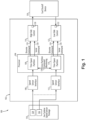
- FIG. 1 is a schematic view of an embodiment of a system constructed in accordance with the present disclosure, showing the processor with two separate time-space partitions for commanding separate high and low side controls for fuel shutoff.
- Fig. 1 a partial view of an embodiment of a system in accordance with the disclosure is shown in Fig. 1 and is designated generally by reference character 100.
- the systems and methods described herein can be used to provide overspeed protection in gas turbine engines wherein the system and method do not introduce any single point failure scenarios to the overspeed protection that would result in commanding fuel off, even for single channel overspeed protection in electronic engine control units (EECUs).
- EECUs electronic engine control units
- the system 100 includes an EECU overspeed protection component 102, which includes a processor 104.
- a first speed sensor interface 106 is operatively connected to a first time-space partition 108 of the processor 104.
- the first speed sensor interface 106 is configured to receive input from a gas turbine speed sensor package 110 and to provide output indicative of engine speed to the first time-space partition 108 based on the input from the sensor package 110.
- the sensor package 110 includes a first sensor 134 with a first channel connecting the first sensor 134 to the first speed sensor interface 106, and a second sensor 136 with a second channel connecting the second sensor 136 to the second speed sensor interface 112.
- the sensor package 110 need only includes a single sensor 134 with a sensor channel connecting the single sensor 134 to both the first and second speed sensor interfaces 106, 112 as indicated in Fig. 1 with the broken line.
- a second speed sensor interface 112 is operatively connected to a second time-space partition 114 of the processor.
- the first speed sensor interface 112 is configured to receive input from the sensor package 110 and to provide output indicative of engine speed to the second time-space partition 114 based on the input from the sensor package 110.
- the time-space partitions 108, 114 can each reside in a single core of the processor 104, and each reserves specific time slots on the schedule of the processor 104, as well as reserving resources of the processor 104 to perform its respective function on the processor 104.
- Processor 104 where the time-space partitions reside, can include a lockstep core, i.e. there can be one or more redundant cores on the processor 104 with identical configurations for cross-checking.
- a high side control 116 is operatively connected to the first time-time space partition 108 to receive a discrete command 118 from the first time-space partition 108, and to receive a separate serial command 120 from the first time-space partition 108, i.e. where the discrete and serial commands 118, 120 are communicated on separate respective lines or channels.
- a low side control 122 is operatively connected to the second time-time space partition 114 to receive a discrete command 124 from the second time-space partition 114, and to receive a separate serial command 126 from the second time-space partition 114, i.e. where the discrete and serial commands 124, 126 are communicated on separate respective lines or channels.
- the first and second time-space partitions 108, 114 are each configured to output a respective ON/OFF discrete command 118, 124 to the respective high side control 116 and the low side control 122.
- the first and second time-space partitions 108, 114 are also each configured to output a respective coded series of ON/OFF bits in a predetermined pattern as serial commands 120, 126 to the respective high side control 116 and the low side control 112, i.e. on separate channels or communication lines from the discrete commands 118, 124. This allows the high and low side controls 116, 122 to verify the ON/OFF discrete commands 118, 124 are not in a stuck state.
- the first and second time-space partitions 108, 114 are both within a single core of the processor 104.
- a lockstep core of the processor 104 can be operatively connected to the single core of the processor 104 for verifying all operations/calculations of the single core. Only if both of the commands 118, 120 to the high side control 116 concur in commanding fuel shutoff, the high side control 116 commands the fuel shutoff device 128 for fuel shutoff as described below. Similarly, only if both of the commands 124, 126 to the low side control 122 commands the fuel shutoff device 128 for fuel shutoff as described below.
- the high and low side controls 116, 122 are configured to connect to a fuel shutoff device 128, such as a valve with a solenoid or other actuator, a power cutoff for fuel pump, or the like, that is located outside the EECU overspeed protection component 102.
- the high and low side controls 116, 122 connect to the fuel shutoff device 128 in manner that requires consensus between the high and low side controls 116, 122 to control the fuel shutoff device 128 to shutoff fuel flow to an engine.
- Each of the high and low side controls 116, 122 includes a respective switch 130, 132 which the respective high or low side control 116, 122 controls based on the input received from the processor 104.
- switches 130, 132 are both closed, a loop is completed, through a first switch 130, through the fuel shutoff device 128, and through a second switch 132, e.g., closing a loop allowing current to flow from the high side, through the fuel shutoff, and then back through the low side to a ground, to ensure consensus between the high and low side controls 116, 122 or else the fuel shutoff device 128 will not shut off fuel flow to the engine.
- a method of overspeed protection for a gas turbine engine includes receiving input from a first speed sensor interface 106 indicative of engine speed into a first time-space partition 108 of a processor and receiving input from a second speed sensor interface 112 indicative of engine speed into a second time-space partition 114 of the processor 104.
- the first time-space partition 108 outputs the first discrete 118 command to the high side control 116 and outputs the first serial command 120 to the high side control 116.
- the high side control 116 closes the first switch 130 only if the discrete command 118 is ON and the serial command 120 matches a predetermined code.
- the second time-space partition 114 outputs the second discrete command 124 to the low side control 122 and outputs the second serial command 126 to the low side control 122.
- the low side control 122 closes the second switch 132 of the low side control only if the second discrete 124 command is ON and the second serial command 126 matches a predetermined code. Both of the serial commands 120, 126 can use the same sequence or code, or they can each have their own respective sequence or code.
- the method includes actuating the fuel shutoff device 128 only if the first and second switches 130, 132 are both closed.
- the processor 104 includes a connection 138 for cross-partition command monitoring between the first and second time-space partitions 108, 114.
- the method can include checking output of the first and second time-space partitions 108, 114 with a lockstep core of the processor 104.
- the lockstep core performs all of the same exact calculations as the main core. However, it checks the main core at a lower level, i.e., the lockstep core checks that the actual instructions and results of instructions of the two cores are identical (without concerns for what the instructions and results actually mean).
- the method can also include cross partition monitoring.
- the cross partition monitoring is not the same as the lock step core cross check.
- the cross partition monitoring allows the two partitions to exchange signals with one another.
- the signals being exchanged can be used to ensure that both time-space partitions agree upon what the state of the discrete/serial commands should be, e.g., if one time-space partition thinks the high/low side control should be turned on, but the other thinks it should be turned off, this may be indicative of a failure.
- This cross partition monitoring can all take place within the main core.
- the systems and methods disclosed herein provide an EECU overspeed protection architecture that can utilize numerous features to preclude a single point failure that would result in commanding fuel off within the EECU from commanding fuel off, while using only a single processor.
- These features include separate high side and low side fuel shut off command control, a processor with a lockstep core, time-space partitions within the processor software and memory, one each for high and low side command control, cross partition command monitoring, identical engine speed input interfaces, one for each time space partition, and fuel shut off command generation that utilizes both discrete and serial communication outputs from each time space partitions of the processor, in order to benefit from dissimilarity.
- a single control channel EECU two processors may be used in the overspeed protection function to preclude a single point failure within the EECU from commanding fuel off.
- the single processor architecture presented herein can provide in reduced cost, complexity, size, weight, and power utilization relative to a two processor architecture, while still precluding single point failures from shutting off fuel to the engine.
Landscapes
- Engineering & Computer Science (AREA)
- Chemical & Material Sciences (AREA)
- Combustion & Propulsion (AREA)
- Mechanical Engineering (AREA)
- General Engineering & Computer Science (AREA)
- Physics & Mathematics (AREA)
- General Physics & Mathematics (AREA)
- Automation & Control Theory (AREA)
- Combined Controls Of Internal Combustion Engines (AREA)
Applications Claiming Priority (1)
| Application Number | Priority Date | Filing Date | Title |
|---|---|---|---|
| US18/126,112 US20240318605A1 (en) | 2023-03-24 | 2023-03-24 | Single processor, single channel electronic engine control overspeed protection for gas turbine engines |
Publications (1)
| Publication Number | Publication Date |
|---|---|
| EP4459104A1 true EP4459104A1 (de) | 2024-11-06 |
Family
ID=90473471
Family Applications (1)
| Application Number | Title | Priority Date | Filing Date |
|---|---|---|---|
| EP24166029.9A Pending EP4459104A1 (de) | 2023-03-24 | 2024-03-25 | Einprozessor-einkanal-überdrehzahlschutz für eine elektronische motorsteuerung für gasturbinenmotoren |
Country Status (2)
| Country | Link |
|---|---|
| US (1) | US20240318605A1 (de) |
| EP (1) | EP4459104A1 (de) |
Citations (4)
| Publication number | Priority date | Publication date | Assignee | Title |
|---|---|---|---|---|
| US3785148A (en) * | 1971-10-14 | 1974-01-15 | Westinghouse Electric Corp | Electronic system and method for operating a steam turbine with independent overspeed protection especially adapted for a nuclear reactor powered steam turbine |
| EP2722493A2 (de) * | 2012-10-19 | 2014-04-23 | General Electric Company | Fehlerdetektionssystem und Verfahren für Überdrehzahlschutz-Drehzahlsensoren |
| FR3099789A1 (fr) * | 2019-08-05 | 2021-02-12 | Safran Aircraft Engines | Procédé de détection de pannes d’un système de régulation et de protection contre la survitesse pour turbomachine |
| US20230407761A1 (en) * | 2022-06-21 | 2023-12-21 | General Electric Company | Electronic overspeed protection system and method |
Family Cites Families (19)
| Publication number | Priority date | Publication date | Assignee | Title |
|---|---|---|---|---|
| US4594668A (en) * | 1983-02-16 | 1986-06-10 | Allied Corporation | Turbocharger control system |
| US4604701A (en) * | 1983-02-16 | 1986-08-05 | Allied Corporation | Fail-soft turbocharger control system |
| GB0224039D0 (en) * | 2002-10-16 | 2002-11-27 | Rolls Royce Plc | Control system |
| US8246294B2 (en) * | 2007-01-16 | 2012-08-21 | Hamilton Sundstrand Corporation | Gas turbine overspeed protection system |
| US20120066551A1 (en) * | 2010-09-15 | 2012-03-15 | Alexandre Palus | Run-time Verification of CPU Operation |
| FR2980174B1 (fr) * | 2011-09-16 | 2013-10-18 | Eurocopter France | Procede de commande pour systeme de securite survitesse, systeme et aeronef associe |
| US9483032B2 (en) * | 2011-09-22 | 2016-11-01 | Hamilton Sundstrand Corporation | Multi-channel protection logic |
| DE202012013193U1 (de) * | 2012-06-26 | 2015-05-06 | INTER CONTROL Hermann Köhler Elektrik GmbH & Co KG | Vorrichtung für eine sicherheitskritische Anwendung |
| FR3023872B1 (fr) * | 2014-07-21 | 2016-07-15 | Sagem Defense Securite | Dispositif de protection contre survitesse d'un moteur d'aeronef |
| US9349226B2 (en) * | 2014-10-09 | 2016-05-24 | The Boeing Company | Systems and methods for detecting faults within operative sub-systems of a vehicle |
| US20160178464A1 (en) * | 2014-12-19 | 2016-06-23 | Rolls-Royce Corporation | Torque sensor monitoring for gas turbine engine |
| US10372569B2 (en) * | 2016-07-25 | 2019-08-06 | General Electric Company | Methods and system for detecting false data injection attacks |
| GB201706269D0 (en) * | 2017-04-20 | 2017-06-07 | Rolls Royce Plc | Fuel control system |
| WO2019094843A1 (en) * | 2017-11-10 | 2019-05-16 | Nvidia Corporation | Systems and methods for safe and reliable autonomous vehicles |
| FR3088897A1 (fr) * | 2018-11-26 | 2020-05-29 | Airbus Operations (S.A.S.) | Système de commande de vol d’un aéronef. |
| US11958622B2 (en) * | 2020-05-15 | 2024-04-16 | Pratt & Whitney Canada Corp. | Protection functions |
| CN115675580A (zh) * | 2021-07-30 | 2023-02-03 | 比亚迪股份有限公司 | 一种轨道列车全冗余测速方法及系统 |
| US12196091B2 (en) * | 2022-04-07 | 2025-01-14 | The Boeing Company | Aircraft auxiliary power unit (APU) controllers and related methods |
| US12529339B2 (en) * | 2022-05-22 | 2026-01-20 | Hamilton Sundstrand Corporation | Engine starter circuits for electric machines |
-
2023
- 2023-03-24 US US18/126,112 patent/US20240318605A1/en not_active Abandoned
-
2024
- 2024-03-25 EP EP24166029.9A patent/EP4459104A1/de active Pending
Patent Citations (4)
| Publication number | Priority date | Publication date | Assignee | Title |
|---|---|---|---|---|
| US3785148A (en) * | 1971-10-14 | 1974-01-15 | Westinghouse Electric Corp | Electronic system and method for operating a steam turbine with independent overspeed protection especially adapted for a nuclear reactor powered steam turbine |
| EP2722493A2 (de) * | 2012-10-19 | 2014-04-23 | General Electric Company | Fehlerdetektionssystem und Verfahren für Überdrehzahlschutz-Drehzahlsensoren |
| FR3099789A1 (fr) * | 2019-08-05 | 2021-02-12 | Safran Aircraft Engines | Procédé de détection de pannes d’un système de régulation et de protection contre la survitesse pour turbomachine |
| US20230407761A1 (en) * | 2022-06-21 | 2023-12-21 | General Electric Company | Electronic overspeed protection system and method |
Also Published As
| Publication number | Publication date |
|---|---|
| US20240318605A1 (en) | 2024-09-26 |
Similar Documents
| Publication | Publication Date | Title |
|---|---|---|
| US3444528A (en) | Redundant computer systems | |
| US8504178B2 (en) | Multiple redundant control system | |
| US4771427A (en) | Equalization in redundant channels | |
| US4774709A (en) | Symmetrization for redundant channels | |
| US20060200278A1 (en) | Generic software fault mitigation | |
| CN105305479B (zh) | 用于发电机组的控制系统和方法 | |
| JP2003517668A (ja) | クリティカル・システムのためのフェイル・セーフ・プロセスの実行、監視、および出力の制御のためのシステムおよび方法 | |
| JPH02138642A (ja) | デュアル・コンピュータ相互点検システム | |
| CN109634171B (zh) | 双核双锁步二取二架构及其安全平台 | |
| CN106444514A (zh) | 一种基于逻辑帧交互的高可靠双余度动力控制器 | |
| US8862934B2 (en) | Redundant computing system and redundant computing method | |
| CN113646707B (zh) | 包括两个冗余控制通道的用于控制飞行器发动机的装置 | |
| US20050223288A1 (en) | Diagnostic fault detection and isolation | |
| EP4459104A1 (de) | Einprozessor-einkanal-überdrehzahlschutz für eine elektronische motorsteuerung für gasturbinenmotoren | |
| JPH087697B2 (ja) | 制御情報のインテグリティを維持するための装置及び方法 | |
| WO2021157567A1 (ja) | 宇宙機液体推進システムの故障診断システム、及び宇宙機液体推進システムの故障診断方法 | |
| CN104698833B (zh) | 冗余控制方法和系统 | |
| CN111044826B (zh) | 检测方法及检测系统 | |
| Hjelmgren et al. | Reliability analysis of a single-engine aircraft FADEC | |
| CN114019991A (zh) | 一种双计算机架构星箭分离程控任务实现方法 | |
| EP0541326A2 (de) | Bestimmung des Zustandes eines Steuerungssystems | |
| CN118462432A (zh) | 具有多机并联轨控发动机的推进系统健康诊断方法及系统 | |
| JPH0944203A (ja) | 冗長化制御システム | |
| CN102858614B (zh) | 继电器控制方法、装置及列车运行控制系统 | |
| CN114114998A (zh) | 一种冗余控制系统及方法 |
Legal Events
| Date | Code | Title | Description |
|---|---|---|---|
| PUAI | Public reference made under article 153(3) epc to a published international application that has entered the european phase |
Free format text: ORIGINAL CODE: 0009012 |
|
| STAA | Information on the status of an ep patent application or granted ep patent |
Free format text: STATUS: THE APPLICATION HAS BEEN PUBLISHED |
|
| AK | Designated contracting states |
Kind code of ref document: A1 Designated state(s): AL AT BE BG CH CY CZ DE DK EE ES FI FR GB GR HR HU IE IS IT LI LT LU LV MC ME MK MT NL NO PL PT RO RS SE SI SK SM TR |
|
| STAA | Information on the status of an ep patent application or granted ep patent |
Free format text: STATUS: REQUEST FOR EXAMINATION WAS MADE |
|
| 17P | Request for examination filed |
Effective date: 20250505 |