EP4458302A1 - Adaptive führungsvorrichtung und transkatheterbehandlungssystem - Google Patents
Adaptive führungsvorrichtung und transkatheterbehandlungssystem Download PDFInfo
- Publication number
- EP4458302A1 EP4458302A1 EP22914824.2A EP22914824A EP4458302A1 EP 4458302 A1 EP4458302 A1 EP 4458302A1 EP 22914824 A EP22914824 A EP 22914824A EP 4458302 A1 EP4458302 A1 EP 4458302A1
- Authority
- EP
- European Patent Office
- Prior art keywords
- guiding device
- segment
- flexible catheter
- adaptive
- section
- Prior art date
- Legal status (The legal status is an assumption and is not a legal conclusion. Google has not performed a legal analysis and makes no representation as to the accuracy of the status listed.)
- Pending
Links
Images


Classifications
-
- A—HUMAN NECESSITIES
- A61—MEDICAL OR VETERINARY SCIENCE; HYGIENE
- A61B—DIAGNOSIS; SURGERY; IDENTIFICATION
- A61B18/00—Surgical instruments, devices or methods for transferring non-mechanical forms of energy to or from the body
- A61B18/04—Surgical instruments, devices or methods for transferring non-mechanical forms of energy to or from the body by heating
- A61B18/12—Surgical instruments, devices or methods for transferring non-mechanical forms of energy to or from the body by heating by passing a current through the tissue to be heated, e.g. high-frequency current
- A61B18/14—Probes or electrodes therefor
- A61B18/1482—Probes or electrodes therefor having a long rigid shaft for accessing the inner body transcutaneously in minimal invasive surgery, e.g. laparoscopy
-
- A—HUMAN NECESSITIES
- A61—MEDICAL OR VETERINARY SCIENCE; HYGIENE
- A61B—DIAGNOSIS; SURGERY; IDENTIFICATION
- A61B18/00—Surgical instruments, devices or methods for transferring non-mechanical forms of energy to or from the body
- A61B18/04—Surgical instruments, devices or methods for transferring non-mechanical forms of energy to or from the body by heating
- A61B18/12—Surgical instruments, devices or methods for transferring non-mechanical forms of energy to or from the body by heating by passing a current through the tissue to be heated, e.g. high-frequency current
- A61B18/14—Probes or electrodes therefor
- A61B18/1492—Probes or electrodes therefor having a flexible, catheter-like structure, e.g. for heart ablation
-
- A—HUMAN NECESSITIES
- A61—MEDICAL OR VETERINARY SCIENCE; HYGIENE
- A61M—DEVICES FOR INTRODUCING MEDIA INTO, OR ONTO, THE BODY; DEVICES FOR TRANSDUCING BODY MEDIA OR FOR TAKING MEDIA FROM THE BODY; DEVICES FOR PRODUCING OR ENDING SLEEP OR STUPOR
- A61M25/00—Catheters; Hollow probes
- A61M25/0021—Catheters; Hollow probes characterised by the form of the tubing
- A61M25/0041—Catheters; Hollow probes characterised by the form of the tubing pre-formed, e.g. specially adapted to fit with the anatomy of body channels
-
- A—HUMAN NECESSITIES
- A61—MEDICAL OR VETERINARY SCIENCE; HYGIENE
- A61M—DEVICES FOR INTRODUCING MEDIA INTO, OR ONTO, THE BODY; DEVICES FOR TRANSDUCING BODY MEDIA OR FOR TAKING MEDIA FROM THE BODY; DEVICES FOR PRODUCING OR ENDING SLEEP OR STUPOR
- A61M25/00—Catheters; Hollow probes
- A61M25/0043—Catheters; Hollow probes characterised by structural features
- A61M25/0045—Catheters; Hollow probes characterised by structural features multi-layered, e.g. coated
-
- A—HUMAN NECESSITIES
- A61—MEDICAL OR VETERINARY SCIENCE; HYGIENE
- A61M—DEVICES FOR INTRODUCING MEDIA INTO, OR ONTO, THE BODY; DEVICES FOR TRANSDUCING BODY MEDIA OR FOR TAKING MEDIA FROM THE BODY; DEVICES FOR PRODUCING OR ENDING SLEEP OR STUPOR
- A61M25/00—Catheters; Hollow probes
- A61M25/0043—Catheters; Hollow probes characterised by structural features
- A61M25/0054—Catheters; Hollow probes characterised by structural features with regions for increasing flexibility
-
- A—HUMAN NECESSITIES
- A61—MEDICAL OR VETERINARY SCIENCE; HYGIENE
- A61M—DEVICES FOR INTRODUCING MEDIA INTO, OR ONTO, THE BODY; DEVICES FOR TRANSDUCING BODY MEDIA OR FOR TAKING MEDIA FROM THE BODY; DEVICES FOR PRODUCING OR ENDING SLEEP OR STUPOR
- A61M25/00—Catheters; Hollow probes
- A61M25/0067—Catheters; Hollow probes characterised by the distal end, e.g. tips
- A61M25/0068—Static characteristics of the catheter tip, e.g. shape, atraumatic tip, curved tip or tip structure
-
- A—HUMAN NECESSITIES
- A61—MEDICAL OR VETERINARY SCIENCE; HYGIENE
- A61M—DEVICES FOR INTRODUCING MEDIA INTO, OR ONTO, THE BODY; DEVICES FOR TRANSDUCING BODY MEDIA OR FOR TAKING MEDIA FROM THE BODY; DEVICES FOR PRODUCING OR ENDING SLEEP OR STUPOR
- A61M25/00—Catheters; Hollow probes
- A61M25/01—Introducing, guiding, advancing, emplacing or holding catheters
- A61M25/0105—Steering means as part of the catheter or advancing means; Markers for positioning
- A61M25/0133—Tip steering devices
- A61M25/0147—Tip steering devices with movable mechanical means, e.g. pull wires
-
- A—HUMAN NECESSITIES
- A61—MEDICAL OR VETERINARY SCIENCE; HYGIENE
- A61M—DEVICES FOR INTRODUCING MEDIA INTO, OR ONTO, THE BODY; DEVICES FOR TRANSDUCING BODY MEDIA OR FOR TAKING MEDIA FROM THE BODY; DEVICES FOR PRODUCING OR ENDING SLEEP OR STUPOR
- A61M25/00—Catheters; Hollow probes
- A61M25/01—Introducing, guiding, advancing, emplacing or holding catheters
- A61M25/06—Body-piercing guide needles or the like
- A61M25/0662—Guide tubes
-
- A—HUMAN NECESSITIES
- A61—MEDICAL OR VETERINARY SCIENCE; HYGIENE
- A61M—DEVICES FOR INTRODUCING MEDIA INTO, OR ONTO, THE BODY; DEVICES FOR TRANSDUCING BODY MEDIA OR FOR TAKING MEDIA FROM THE BODY; DEVICES FOR PRODUCING OR ENDING SLEEP OR STUPOR
- A61M37/00—Other apparatus for introducing media into the body; Percutany, i.e. introducing medicines into the body by diffusion through the skin
-
- A—HUMAN NECESSITIES
- A61—MEDICAL OR VETERINARY SCIENCE; HYGIENE
- A61B—DIAGNOSIS; SURGERY; IDENTIFICATION
- A61B17/00—Surgical instruments, devices or methods
- A61B2017/00831—Material properties
- A61B2017/00867—Material properties shape memory effect
- A61B2017/00871—Material properties shape memory effect polymeric
-
- A—HUMAN NECESSITIES
- A61—MEDICAL OR VETERINARY SCIENCE; HYGIENE
- A61B—DIAGNOSIS; SURGERY; IDENTIFICATION
- A61B18/00—Surgical instruments, devices or methods for transferring non-mechanical forms of energy to or from the body
- A61B2018/00315—Surgical instruments, devices or methods for transferring non-mechanical forms of energy to or from the body for treatment of particular body parts
- A61B2018/00345—Vascular system
- A61B2018/00351—Heart
-
- A—HUMAN NECESSITIES
- A61—MEDICAL OR VETERINARY SCIENCE; HYGIENE
- A61B—DIAGNOSIS; SURGERY; IDENTIFICATION
- A61B18/00—Surgical instruments, devices or methods for transferring non-mechanical forms of energy to or from the body
- A61B2018/00571—Surgical instruments, devices or methods for transferring non-mechanical forms of energy to or from the body for achieving a particular surgical effect
- A61B2018/00577—Ablation
-
- A—HUMAN NECESSITIES
- A61—MEDICAL OR VETERINARY SCIENCE; HYGIENE
- A61B—DIAGNOSIS; SURGERY; IDENTIFICATION
- A61B18/00—Surgical instruments, devices or methods for transferring non-mechanical forms of energy to or from the body
- A61B18/04—Surgical instruments, devices or methods for transferring non-mechanical forms of energy to or from the body by heating
- A61B18/12—Surgical instruments, devices or methods for transferring non-mechanical forms of energy to or from the body by heating by passing a current through the tissue to be heated, e.g. high-frequency current
- A61B18/14—Probes or electrodes therefor
- A61B2018/1405—Electrodes having a specific shape
- A61B2018/1425—Needle
-
- A—HUMAN NECESSITIES
- A61—MEDICAL OR VETERINARY SCIENCE; HYGIENE
- A61M—DEVICES FOR INTRODUCING MEDIA INTO, OR ONTO, THE BODY; DEVICES FOR TRANSDUCING BODY MEDIA OR FOR TAKING MEDIA FROM THE BODY; DEVICES FOR PRODUCING OR ENDING SLEEP OR STUPOR
- A61M25/00—Catheters; Hollow probes
- A61M25/01—Introducing, guiding, advancing, emplacing or holding catheters
- A61M25/0105—Steering means as part of the catheter or advancing means; Markers for positioning
- A61M25/0133—Tip steering devices
- A61M25/0147—Tip steering devices with movable mechanical means, e.g. pull wires
- A61M2025/015—Details of the distal fixation of the movable mechanical means
-
- A—HUMAN NECESSITIES
- A61—MEDICAL OR VETERINARY SCIENCE; HYGIENE
- A61M—DEVICES FOR INTRODUCING MEDIA INTO, OR ONTO, THE BODY; DEVICES FOR TRANSDUCING BODY MEDIA OR FOR TAKING MEDIA FROM THE BODY; DEVICES FOR PRODUCING OR ENDING SLEEP OR STUPOR
- A61M25/00—Catheters; Hollow probes
- A61M25/01—Introducing, guiding, advancing, emplacing or holding catheters
- A61M25/06—Body-piercing guide needles or the like
- A61M25/0662—Guide tubes
- A61M2025/0681—Systems with catheter and outer tubing, e.g. sheath, sleeve or guide tube
-
- A—HUMAN NECESSITIES
- A61—MEDICAL OR VETERINARY SCIENCE; HYGIENE
- A61M—DEVICES FOR INTRODUCING MEDIA INTO, OR ONTO, THE BODY; DEVICES FOR TRANSDUCING BODY MEDIA OR FOR TAKING MEDIA FROM THE BODY; DEVICES FOR PRODUCING OR ENDING SLEEP OR STUPOR
- A61M2210/00—Anatomical parts of the body
- A61M2210/12—Blood circulatory system
- A61M2210/125—Heart
-
- A—HUMAN NECESSITIES
- A61—MEDICAL OR VETERINARY SCIENCE; HYGIENE
- A61M—DEVICES FOR INTRODUCING MEDIA INTO, OR ONTO, THE BODY; DEVICES FOR TRANSDUCING BODY MEDIA OR FOR TAKING MEDIA FROM THE BODY; DEVICES FOR PRODUCING OR ENDING SLEEP OR STUPOR
- A61M2210/00—Anatomical parts of the body
- A61M2210/12—Blood circulatory system
- A61M2210/127—Aorta
-
- A—HUMAN NECESSITIES
- A61—MEDICAL OR VETERINARY SCIENCE; HYGIENE
- A61M—DEVICES FOR INTRODUCING MEDIA INTO, OR ONTO, THE BODY; DEVICES FOR TRANSDUCING BODY MEDIA OR FOR TAKING MEDIA FROM THE BODY; DEVICES FOR PRODUCING OR ENDING SLEEP OR STUPOR
- A61M25/00—Catheters; Hollow probes
- A61M25/0043—Catheters; Hollow probes characterised by structural features
- A61M25/005—Catheters; Hollow probes characterised by structural features with embedded materials for reinforcement, e.g. wires, coils, braids
-
- A—HUMAN NECESSITIES
- A61—MEDICAL OR VETERINARY SCIENCE; HYGIENE
- A61M—DEVICES FOR INTRODUCING MEDIA INTO, OR ONTO, THE BODY; DEVICES FOR TRANSDUCING BODY MEDIA OR FOR TAKING MEDIA FROM THE BODY; DEVICES FOR PRODUCING OR ENDING SLEEP OR STUPOR
- A61M25/00—Catheters; Hollow probes
- A61M25/0067—Catheters; Hollow probes characterised by the distal end, e.g. tips
- A61M25/0082—Catheter tip comprising a tool
- A61M25/0084—Catheter tip comprising a tool being one or more injection needles
-
- A—HUMAN NECESSITIES
- A61—MEDICAL OR VETERINARY SCIENCE; HYGIENE
- A61M—DEVICES FOR INTRODUCING MEDIA INTO, OR ONTO, THE BODY; DEVICES FOR TRANSDUCING BODY MEDIA OR FOR TAKING MEDIA FROM THE BODY; DEVICES FOR PRODUCING OR ENDING SLEEP OR STUPOR
- A61M25/00—Catheters; Hollow probes
- A61M25/01—Introducing, guiding, advancing, emplacing or holding catheters
- A61M25/0105—Steering means as part of the catheter or advancing means; Markers for positioning
- A61M25/0108—Steering means as part of the catheter or advancing means; Markers for positioning using radio-opaque or ultrasound markers
Definitions
- the present disclosure relates to the technical field of medical devices, and in particular to an adaptive guiding device and a transcatheter treatment system.
- interventional surgery is becoming more and more common, which is characterized by opening a small operating window on the patient's body surface, delivering devices such as catheter through the vascular access to the treatment site to establish a passage from outside the body to inside the body, and then delivering various treatment devices through this passage for interventional treatment.
- the device used to establish a passage from outside the body to inside the body is the so-called guiding device.
- the guiding device needs to adapt to the morphologies of different blood vessels, and is preferred to have a certain degree of adaptability to avoid the risk of irreversibly damaging the blood vessel tissue and reach the diseased area quickly and accurately for interventional treatment.
- patent application No. WO2020/068601A1 discloses a guiding device for catheter-type interventional device, which uses a distal flexible segment as a hinge structure to cause lateral displacement by applying a certain axial force, to adapt to the curved blood vessel shape.
- conventional interventional paths include: puncture via the femoral vein, through the inferior vena cava, right atrium to the right ventricle, or through the inferior vena cava, right atrium, left atrium to the left ventricle; or puncture via the femoral artery, through the aortic arch to the left ventricle.
- the guiding device is required to include multiple bendable sections, i.e., multiple sections hinged in sequence and cooperated with each other, which will increase the structural complexity and reduce the stability.
- the hinge structure when being displaced laterally, requires large avoidance spaces, and the avoidance spaces will be gradually reduced after the lateral displacement, increasing the bending difficulty.
- the tissue because the vascular tissue is flexible with strong compliance, the tissue may extend into the avoidance area, causing irreversible damage to the vascular tissue and increasing the operation risk of the treatment device.
- the present disclosure discloses an adaptive guiding device to solve the problems of the existing guiding devices of poor adaptability and easy damage to the human body.
- Another object of the present disclosure is to provide a transcatheter treatment system to solve the problems of the existing transcatheter treatment systems of poor adaptability and easy damage to the human body.
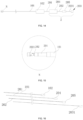
- the adaptive guiding device includes a hollow flexible catheter, which is pre-shaped and has a bend in a natural state.
- a distal part of the flexible catheter includes a distal section, the distal section includes a transition segment and a straight segment, the transition segment is bendable so as to change an orientation of the straight segment, and a bending force application point is adjacent to a connection of the transition segment with the straight segment.
- the straight segment has a length I, where 0 ⁇ I ⁇ 80 mm.
- the length of the straight segment is in a range of 40 to 80 mm.
- the transition segment is pre-shaped into an arc shape.
- the transition segment has a central angle a5, and an arc bend of the transition segment has a radius R5, where 15° ⁇ a5 ⁇ 70°, and 25 mm ⁇ R5 ⁇ 45 mm.
- the flexible catheter includes a main section, a trans-aortic arch section and the distal section connected in sequence from proximal to distal and communicated with each other, and wherein the trans-aortic arch section has a curved structure simulating an aortic arch shape, and two ends of the transition segment are respectively tangent to the straight segment and the trans-aortic arch section.
- the flexible catheter in the natural state is bent multiple times along its central axis toward different planes.
- the flexible catheter is bent at least five times.
- angles between planes of at least four consecutive bends are less than 90°.
- an angle between two planes of one bend closest to a distal end is greater than 90°.
- the trans-aortic arch section includes a first arc segment, a second arc segment, a third arc segment and a fourth arc segment that are sequentially connected and tangent one after another, the first arc segment, the second arc segment, the third arc segment and the fourth arc segment are distributed on different planes, and wherein the first arc segment is connected and communicated with the main section, and the fourth arc segment is connected and communicated with the distal section.
- the first arc segment has an angle a1, an arc bend of the first arc segment has a radius R1; the second arc segment has an angle a2, an arc bend of the second arc segment has a radius R2; the third arc segment has an angle a3, the arc bend of the third arc segment has a radius R3; and the fourth arc segment has an angle a4, and an arc bend of the fourth arc segment has a radius R4.
- angles between a central axis of a projection of the straight segment on a first plane, a second plane, and a third plane, respectively, and a central axis of a projection of the main section are ⁇ , ⁇ , and ⁇ respectively, wherein the first plane is a vertical plane, the second plane is perpendicular plane perpendicular to the vertical plane, and the third plane is a horizontal plane perpendicular to both the vertical plane and the perpendicular plane, where 35° ⁇ ⁇ ⁇ 85°, 25° ⁇ ⁇ ⁇ 80°, and 20° ⁇ ⁇ ⁇ 75°.
- an angle between a central axis of a projection of the transition segment on the first plane and the central axis of the main section is ⁇ , where 0 ⁇ ⁇ ⁇ 45°.
- the adaptive guiding device further includes an operating handle, and the operating handle is connected to the main section and is configured to drive the flexible catheter to move axially and circumferentially.
- the adaptive guiding device further includes a pull assembly, wherein the pull assembly includes a pull wire, a guiding passageway and an anchor ring, the guiding passageway is defined in a wall of the flexible catheter for the pull wire to pass through, the anchor ring is fixedly connected to the transition segment of the distal section, and the pull wire is connected to the anchor ring and the operating handle respectively.
- the pull assembly includes a pull wire, a guiding passageway and an anchor ring
- the guiding passageway is defined in a wall of the flexible catheter for the pull wire to pass through
- the anchor ring is fixedly connected to the transition segment of the distal section
- the pull wire is connected to the anchor ring and the operating handle respectively.
- the anchor ring is adjacent to the connection of the transition segment with the straight segment.
- the anchor ring also serves as an imaging mark.
- a distal end of the straight segment is further provided with an imaging mark.
- the pull wire is deflected around a central axis of the flexible catheter.
- the pull wire is deflected by 90° around the central axis of the flexible catheter.
- a start point of the guiding passageway at the distal section is A
- point B is deflected by 90° relative to the point A in a circumferential direction of the flexible catheter
- a transitional guiding section is formed between point A and point B, wherein the transitional guiding section extends along a part or an entire of the trans-aortic arch section, or a part or an entire the main section.
- the transitional guiding section has a length of L, where 0 mm ⁇ L ⁇ 250 mm.
- the present disclosure discloses a transcatheter treatment system, including the adaptive guiding device as mentioned above and a treatment device movably received in the flexible catheter, wherein the flexible catheter functions to establish a path from outside a human body to inside the human body, and the treatment device is configured to pass through an aortic arch via the flexible catheter.
- the treatment device is selected from at least one of a myocardial injection device, a myocardial ablation device, a valve repair device, or a valve replacement device.
- the treatment device includes a bending sheath, an inner sheath and a treatment assembly, wherein the bending sheath is movably inserted in the flexible catheter and is bendable in a single direction, the inner sheath is movably inserted in the bending sheath, and the treatment assembly is inserted in the inner sheath.
- a bending direction of the bending sheath is different from a bending direction of the distal section of the flexible catheter of the adaptive guiding device.
- the bending direction of the bending sheath is substantially perpendicular to the bending direction of the distal section of the flexible catheter of the adaptive guiding device.
- a distal end of the inner sheath is fixedly connected with a limiting element, and after the inner sheath extends from a distal end of the bending sheath, the limiting element is configured to contact a tissue surface.
- the treatment assembly is selected from at least one of an injection assembly, an ablation assembly, a prosthetic heart valve, an annuloplasty ring, a valve clamping device, a suture, and a tissue anchor or a tissue puncture member.
- the embodiments of the present disclosure at least have the following benefits: by providing the guiding device with a flexible catheter which is pre-shaped and bendable, the adaptability of the guiding device to the blood vessel morphology can be improved, in its natural state, it can better adapt to the complex anatomical morphology of the human aortic arch, thereby simplifying the guidance operation, reducing the pressure to human blood vessels, and improving the reliability of the device.
- the structure of the guiding device is simplified, the guiding device in use does not require a large avoidance space, so that the guiding device has a larger operation and adjustment space and a more convenient initial position for adjustment, and the tissue can be prevented from extending into the avoidance area, thereby reducing blood vessel damage and improving the operation safety of the device.
- an adaptive guiding device 1 which includes a hollow flexible catheter 101 of a certain length.
- the flexible catheter 101 has been pre-shaped, and has bends in its natural state.
- the distal part of the entire flexible catheter 101 is a distal section 1013.
- the distal section 1013 at least includes a transition segment 10131 and a straight segment 10132.
- the transition segment 10131 is bendable.
- the flexible catheter 101 is bent at least five times relative to its own central axis in different planes, wherein the angle between the two planes of one bend closest to the distal end is greater than 90°, and the angles between the planes of at least four consecutive bends is less than 90°, so that at least part of the flexible catheter can conform to the anatomical shape of the aortic arch.
- the angle between the planes of at least four consecutive bends being less than 90° is explained referring to the arc segments below.
- the first arc segment 10121, the second arc segment 10222, the third arc segment 10123, and the fourth arc segment 10124 each define a plane, and the angle (deflection amplitude) between the planes where adjacent arc segments are located is less than 90°.
- the first arc segment 10121 is located on the plane W1
- the second arc segment 1022 is located on the plane W2
- the angle between the plane W1 and plane W2 is less than 90°.
- the other arc segments Since the arc segments are not coplanar, bending in different planes is achieved.
- the angle between the two planes of one bend closest to the distal end is greater than 90°.
- the guiding device By providing the guiding device with a flexible catheter 101 which is pre-shaped with a specific shape, the distal end of the flexible catheter 101 in a natural state can conform to the anatomical shape of the aortic arch of the human body, thereby simplifying the guiding operation, improving the reliability of the device, reducing the pressure to human blood vessels and thus reducing the damage to blood vessels, and improving the operation safety of the treatment device.
- the flexible catheter 101 in order to provide the adaptive guiding device 1 with strong compliance in human blood vessels, as well as certain pushability and twist resistance, the flexible catheter 101 preferably uses a pre-shaped multi-layer sheath structure.
- the adaptive guiding device 1 is an adaptive guiding sheath.
- Pre-shaping refers to the process of placing the flexible catheter in a mold with a specific shape and heating it to a certain temperature to form the flexible catheter into a specific shape.
- pre-shaping specifically includes the following steps: placing the multi-layer sheath in the mold the inner cavity of which corresponding to the anatomical shape of the aortic arch, heating the placed multi-layer sheath and the mold together, cooling to room temperature, and de-molding. The heating temperature and time depend on the material and structure of the sheath.
- the flexible catheter 101 can be a metal cut tube, a metal wire braided tube, or a flexible tube made of other polymer materials, which only needs to be pre-shaped so that the catheter has a specific shape adapted to the anatomical shape of the aortic arch.
- the multi-layer sheath structure of the flexible catheter 101 includes at least three layers, including an inner layer (not shown in the figure), a middle layer (not shown in the figure) and an outer layer (not shown in the figure) arranged sequentially from the inside to the outside.
- the inner layer is a polymer inner film, which can be made of PTFE (polytetrafluoroethylene).
- the middle layer is a metal braided mesh, which can be stainless steel mesh or tungsten wire mesh.
- the outer layer is a polymer outer film, and can be optionally made of PEBAX.
- the hardness of the outer film of the multi-layer sheath at different parts can be varied to adapt to the curvature of different blood vessels, and to improve the pushability and twist resistance of the sheath.
- the commonly used hardness specifications of PEBAX are 25D, 35D, 55D, 72D, etc.
- PEBAX with different hardness can be used for different parts of the outer film of the catheter as needed to meet the performance requirements of different parts of the catheter.
- the flexible catheter 101 includes a main section 1011, a trans-aortic arch section 1012 and a distal section 1013 connected in sequence from the proximal end to the distal end, wherein the trans-aortic arch section 1012 has a curved structure simulating the anatomical shape of the aortic arch 3.
- the main section 1011 is the starting section of the overall flexible catheter 101 and provides support for the overall structure.
- the trans-aortic arch section 1012 simulates the anatomical shape of the aortic arch 3 and is configured to traverse the aortic arch 3 of the human heart, to improve the compliance with the aortic arch 3 and reduce the pressure to vessels.
- the distal section 1013 is an output end of the catheter and configured to provide guidance for the treatment device installed in the flexible catheter 101.
- the side close to the main section 1011 is designated as the proximal end of the flexible catheter 101
- the side close to the distal section 1013 is designated as the distal end of the flexible catheter 101.
- the treatment device is inserted from the proximal end of the flexible catheter 101 and extends out from the distal end, that is, the lumen inlet of the flexible catheter 101 is located at its proximal end, and the lumen outlet is located at its distal end.
- the main section 1011 is usually a straight section or an approximately straight section, and mainly functions to traverse the femoral artery and descending aorta to reach the start of the turning part of the aortic arch 3. Therefore, it is the longest section of the guiding sheath, and the length can be in the range of 540 mm to 840 mm.
- the main section 1011 In order to avoid twisting or bending of the flexible catheter 101 in curved blood vessels and to increase the twist resistance of the flexible catheter 101, the main section 1011 usually has a high hardness.
- the main section 1011 preferably has a PEBAX outer film with a hardness of 72D.
- the trans-aortic arch section 1012 is connected to the main section 1011 and the distal section 1013 for traversing and conforming to the anatomical shape of the aortic arch 3.
- the trans-aortic arch section 1012 uses a curved arc segment simulating the shape and curvature of the aortic arch 3. Since the aortic arch 3 is a three-dimensional arch, the more the arc segments that simulate the aortic arch, the better the guiding device can conform to the aortic arch 3. However, the processing difficulty will be increased accordingly. Further, too many arc segments will cause the tube of the trans-aortic arch section 1012 to be stiffer, reducing crossability, and affecting the adaptability.
- the trans-aortic arch section 1012 at least includes a first arc segment 10121, a second arc segment 10222, a third arc segment 10123 and a fourth arc segment 10124 that are sequentially connected and tangent one after another.
- the first arc segment 10121, second arc segment 10222, third arc segment 10123 and fourth arc segment 10124 are located on different planes.
- the first arc segment 10121 is connected with and communicated to the main section 1011, and the fourth arc segment 10124 is connected with and communicated to the distal section 1013.
- the fitness or conformity between the trans-aortic arch section 1012 of the flexible catheter 101 and the aortic arch 3 is higher, the adaptability and crossability are better, and the pressure to blood vessels can be reduced to reduce blood vessel damage.
- the angle of the first arc segment 10121 is a1, and the radius of the arc bend of the first arc segment 10121 is R1; the angle of the second arc segment 10222 is a2, and the radius of the arc bend of the second arc segment 10222 is R2; the angle of the third arc segment 10123 is a3, and the radius of the arc bend of the third arc segment 10123 is R3; the angle of the fourth arc segment 10124 is a4, and the radius of the arc bend of the fourth arc segment 10124 is R4.
- the above parameters are obtained by simulation calculation based on the common structure of the aortic arch 3.
- the trans-aortic arch section 1012 can better conform to the anatomical shape of the aortic arch 3 of most human hearts, and the pressure to blood vessels can be significantly reduced, in order to reduce blood vessel damage and improve the operation safety of the treatment device.
- the hardness of the PEBAX outer film of the trans-aortic arch section 1012 is preferably 55D.
- the distal section 1013 at least includes a transition segment 10131 and a straight segment 10132.
- the transition segment 10131 is arc-shaped, and its two ends are respectively tangent to the straight segment 10132 and the trans-aortic arch section 1012. This can avoid sharply changes in the curvature of the tube of the distal section 1013 and reduce the resistance and difficulty of the treatment device passing through the guiding device.
- the at least five bends obtained by the pre-shaping mentioned above can be understood as four of them correspond to the first arc segment 10121, the second arc segment 10222, the third arc segment 10123 and the fourth arc segment 10124, and the fifth bend corresponds to the transition segment 10131 that is pre-shaped into an arc shape.
- the angle of the transition segment 10131 is a5
- the radius of the arc bend of the transition segment 10131 is R5 ( projection on the first plane 10), where 15° ⁇ a5 ⁇ 70°, and 25 mm ⁇ R5 ⁇ 45 mm.
- the angle a5 of the transition segment 10131 and the radius R5 of the arc bend thereof affect the orientation of the straight segment 10132. Further, the bending radius of the transition segment 10131 will also affect the bending force. The larger the bending radius, the smaller the rigidity of the transition segment 10131, and the smaller the bending force required when bending. However, the bending radius should not be too large otherwise it would affect the crossability of the tube of the transition segment 10131.
- the distal section 1013 in the initial state can point toward the middle position between the anterior papillary muscle 5 and the posterior papillary muscle 6, so that the treatment device that passes through the flexible catheter 101 and enters the heart can have a larger operation and adjustment space and a convenient initial position for adjustment, that is, the delivered treatment device has a wider operation range and coverage, while avoiding affecting the crossability of the tube of the transition segment 10131 and the bending force.
- the angles between the central axis of the projection of the straight segment 10132 on the first plane 10, the second plane 11, and the third plane 12, respectively, and the central axis of the main section 1011 are ⁇ , ⁇ , ⁇ .
- the first plane 10 is a vertical plane
- the second plane 11 is a perpendicular plane perpendicular to the vertical plane
- the third plane 12 is a horizontal plane perpendicular to both the vertical plane and the perpendicular plane, where 35° ⁇ ⁇ ⁇ 85 °, 25° ⁇ ⁇ ⁇ 80°, and 20° ⁇ ⁇ ⁇ 75°.
- first plane 10 and the third plane 12 intersect perpendicularly.
- the perpendicular intersection position is roughly the central axis of the main section 1011.
- the angles a1 to a4 of the first to fourth arc segments can be understood as the corresponding central angles of projections of the segments on the third plane 12.
- the angle a1 can be determined according to its radius R1.
- the angles ⁇ , ⁇ , and ⁇ jointly affect the orientation of the straight segment 10132 at the distal end of the flexible catheter 101.
- the angle ⁇ determines the distance between the distal end of the flexible catheter 101 and the anterior or posterior papillary muscles 5 or 6 in the heart. The smaller the ⁇ , the closer the straight segment 10132 of the flexible catheter 101 is to the posterior papillary muscle 6; and the greater the ⁇ , the closer the straight segment 10132 of the flexible catheter 101 is to the anterior papillary muscle 5.
- the angles ⁇ and ⁇ determine the distance between the straight segment 10132 of the flexible catheter 101 and the interventricular septum or free wall 9 in the heart.
- the straight segment 10132 of the flexible catheter 101 is closer the straight segment 10132 of the flexible catheter 101 is to the free wall 9; and the greater the ⁇ and ⁇ , the closer the straight segment 10132 of the flexible catheter 101 is to the interventricular septum.
- the end of the straight segment 10132 of the flexible catheter 101 can accurately point toward the middle position of the area in front of the papillary muscles, preventing the end of the straight segment 10132 after entering the heart from being initially positioned in other areas except the middle position between the anterior papillary muscle 5 and the posterior papillary muscle 6, so that the straight segment 10132 of the flexible catheter 101 can be located in an appropriate position after entering the heart, and thus the straight segment 10132 of the flexible catheter 101 is easier to point to the target area 7 and quickly lock it.
- the length of the straight segment 10132 is I, where 0 ⁇ I ⁇ 80mm.
- the length of the straight segment 10132 is preferably 40 mm.
- the longer the length of the straight segment 10132 the more accurate the orienting of the treatment device extending out of the straight segment 10132.
- the above range allows the treatment device passing through the straight segment 10132 to accurately reach the target area 7.
- the hardness of the PEBAX outer film of the transition segment 10131 and the straight segment 10132 of the distal section 1013 is preferably 25D.
- the angle between the central axis of the projection of the transition segment 10131 on the first plane 10 and the central axis of the main section 1011 is ⁇ , where the first plane 10 is a vertical plane, and 0 ⁇ ⁇ ⁇ 45°.
- the angle ⁇ affects the initial position of the transition segment 10131 of the distal section 1013. Based on the above settings, it can be ensured that when the adaptive guiding device 1 enters the left ventricle 4, the trans-aortic arch section 1012 of the shaped flexible catheter 101 will be located at the middle position of the aortic arch 3, which provides enough space for the flexible catheter 101 to be displaced laterally during the adjustment process, and also greatly reduces the pressure to the blood vessels and aortic valve 8 in the heart.
- the adaptive guiding device 1 further includes an operating handle 102, which is connected to the main section 1011 and used to drive the flexible catheter 101 to move axially and circumferentially.
- the operating handle 102 is convenient for the operator to hold and operate, so that the flexible catheter 101 can move axially and circumferentially, and thus the distal section 1013 of the flexible catheter 101 can accurately point to the target area 7, providing accurate guidance for the treatment device.
- the operating handle 102 can be a conventional handle.
- the flexible catheter 101 is pre-shaped so that the flexible catheter 101 in a natural state is bent at least five times relative to the central axis in different planes, thereby improving the adaptability of the guiding device to the vascular morphology.
- the guiding device can better adapt to the complex anatomical morphology of the human aortic arch 3, thereby simplifying the guidance operation, reducing the pressure to human blood vessels, and improving the reliability of the device.
- the structure of the guiding device is simplified, and the operation safety of the treatment device is improved.
- the guiding device in use does not require a large avoidance space, so that the guiding device has a larger operation and adjustment space and a more convenient initial position for adjustment, and the tissue can be prevented from extending into the avoidance area, thereby reducing blood vessel damage and improving the operation safety of the treatment device.
- the adaptive guiding device 1 further includes a pull assembly 103 for accurately adjusting the lateral displacement of the distal section 1013 of the flexible catheter 101 to further improve the adaptability to the vascular morphology.
- the pull assembly 103 includes a pull wire 1031, a guiding passageway 1032 and an anchor ring 1033.
- the guiding passageway 1032 is defined in the wall of the flexible catheter 101, that is, the guiding passageway 1032 is defined between the outer layer and the inner layer of the flexible catheter 101, specifically between the inner layer and the middle layer, or between the middle layer and the outer layer.
- the guiding passageway 1032 is configured for the pull wire 1031 to pass through.
- the anchor ring 1033 is fixedly connected to the transition segment 10131 of the distal section 1013, and the pull wire 1031 is fixedly connected to the anchor ring 1033 and the operating handle 102 respectively.
- the pull wire 1031 is a flexible filament with a certain length and toughness, and can be selected from stainless steel braided ropes, non-metallic braided ropes (such as commonly used sutures), steel wires, nickel-titanium wires, etc. In this embodiment, stainless steel braided wires are preferred due to good toughness, bending resistance and flexibility.
- the guiding passageway 1032 is defined in the wall of the flexible catheter and is used for the pull wire 1031 to pass through and protect the pull wire 1031.
- the guiding passageway 1032 can be a PI (polyimide) pipe, a PEEK (poly(ether-ether-ketone)) pipe, a flexible stainless steel cut tube, etc..
- the guiding passageway preferably uses a PI pipe.
- the operating handle 102 pulls the anchor ring 1033 through the pull wire 1031 of the pull assembly 103, thereby pulling the distal section 1013 of the flexible catheter 101, so as to control the movement amplitude and direction of the lateral displacement of the distal section 1013 of the flexible catheter 101, to ensure that the distal section 1013 of the flexible catheter 101 is located at the outflow tract of the aortic arch 3, providing a large space for bending and facilitating further clinical operations.
- the anchor ring 1033 is fixed at the transition segment 10131 of the distal section 1013.
- the transition segment 10131 serves as the to-be-bent segment.
- the pull wire 1031 is pulled by the operating handle 102, so that the transition segment 10131 can be bent accordingly, thereby driving the straight segment 10132 to displace laterally, so as to control the movement amplitude and direction of the lateral displacement of the distal section 1013 of the flexible catheter 101.
- the transition segment 10131 as the to-be-bent segment, as the end thereof is connected with the straight segment 10132, only a slight bending to the transition segment 10131 would cause a significant positional change of the end of the straight segment 10132. That is, only a small bending force is required in order to cause a significant positional change of the end of the distal section 1013 of the flexible catheter 101. Therefore, the movement space required by the flexible catheter 101 itself is reduced, and the output end of the distal section 1013 of the flexible catheter 101 can be adjusted more accurately and reliably.
- the anchor ring 1033 is fixedly connected to one end of the transition segment 10131 close to the straight segment 10132.
- the pull torque can be maximized and the pull force required for adjustment of the straight segment 10132 can be reduced.
- the anchor ring 1033 can be made of stainless steel. In the case where the anchor ring 1033 is made of stainless steel, it can be fixedly connected to the pull wire 1031 by welding. In some embodiments, a single pull wire 1031 can be arranged in the guiding passageway 1032. By welding, one end of the single pull wire 1031 can be fixed to the anchor ring 1033, and the other end can be fixed to the operating handle 102.
- the anchor ring 1033 can be made of other materials, in which case, the pull wire 1031 can be looped and connected to the anchor ring 1033.
- At least two pull wires 1031 are provided, that is, at least a first pull wire and a second pull wire are provided.
- the first pull wire and the second pull wire form a closed loop of a pull wire group, and one end of the pull wire group is connected to the anchor ring 1033, and the other end is connected to the operating handle 102.
- the pull wire group can be pulled by the operating handle 102, so as to pull the distal section 1013 of the flexible catheter 101 to move in different directions.
- each pull wire 1031 is provided with a guiding passageway 1032, avoiding multiple pull wires 1031 being arranged in the same guiding passageway 1032 which would cause blockage or interference with each other, maintaining the reliability of adjustment, reducing the diameter of a single guiding passageway 1032 and reducing the profile of the entire flexible catheter 101.
- the pull wire 1031 and the anchor ring 1033 are preferably connected by welding, which can reduce the outer diameter of the whole of the pull wire 1031 and the anchor ring 1033, thereby reducing the resistance during lateral bending, and also reducing the outer diameter of the flexible catheter 101.
- the material of the anchor ring 1033 is preferably tantalum. Compared with stainless steel, tantalum has a better contrast effect under ultrasound.
- the projection of the guiding passageway 1032 perpendicular to the central axis of the flexible catheter 101 gradually deflects around the central axis.
- the part of the guiding passageway 1032 from the distal section 1013 to the main section 1011 can deflect around the central axis, and the pull wire 1031 passing through the guiding passageway 1032 will deflect accordingly.
- the distal section 1013 can deflect better relative to the main section 1011 with the main section 1011 as the basis for deflection, thereby reducing the deflection of the main section 1011 in the same direction when adjusting the distal section 1013, and reducing the pressure to blood vessels.
- the deflection start point of the guiding passageway 1032 at the distal section 1013 is A, and point B is deflected by 90° relative to the point A in the circumferential direction of the flexible catheter 101.
- a transitional guiding section 10321 is defined between point A and point B.
- the transitional guiding section 10321 extends along a part or the entire of the trans-aortic arch section 1012, or a part or the entire of the main section 1011.
- the terminal point of the deflected part of the guiding passageway 1032 can be set at the trans-aortic arch section 1012 or the main section 1011 in practice according to the desired operation effects.
- the length L of the transitional guiding section 10321 affects the deflection of the flexible catheter 101 during lateral bending. If the length of the transitional guiding section 10321 is too short, during lateral bending, a great bending force is required. If the length L of the transitional guiding section 10321 is too long, for example, if the entire pull wire 1031 extends and deflects from the point A to the operating handle 102, the entire flexible catheter 101 would be prone to deflect toward the pull wire 1031 when adjusting the distal section 1013 of the flexible catheter 101, increasing the deflection amplitude of the flexible catheter 101, increasing the pressure to the blood vessels, and easily causing damage to the blood vessels. In the present disclosure, the length L of the transitional guiding section 10321 is in the range of 0 mm ⁇ L ⁇ 250 mm.
- the length of the transitional guiding section 10321 mainly affects the pull force for the trans-aortic arch section 1012 and the deflection amplitude of the trans-aortic arch section 1012 during bending.
- the length of the transitional guiding section 10321 is preferably 40 mm, so that the pull force for the trans-aortic arch section 1012 and the deflection amplitude of the trans-aortic arch section 1012 during bending can be appropriate.
- the hardness of the PEBAX outer film is proportional to the bending force of the pull wire 1031. The lower the hardness of the PEBAX outer film, the smaller the bending force of the pull wire 1031 when the distal end of the flexible catheter is displaced.
- the PEBAX outer film of the transition segment 10131 is preferably 25D, which not only requires a small bending force, but also ensures a certain strength to prevent the tube of the transition segment 10131 from being pressed by the blood vessel wall and bent.
- the flexible catheter 101 in this embodiment needs to displace laterally in use, it is necessary to provide a fulcrum for the flexible catheter 101 at the aortic arch 3 so that the part of the flexible catheter 101 in front of the fulcrum remains motionless, while in the other part in rear of the fulcrum, the distal section 1013 of the flexible catheter 101 can be displaced laterally by bending, thereby displacing a specified section in a specified direction.
- the fourth arc segment 10124 of the trans-aortic arch section 1012 serves as a fulcrum to abut against the outside of the aortic arch 3, so that when the flexible catheter 101 is displaced laterally, the flexible catheter 101 has an appropriate support force, while the first arc segment 10121, the second arc segment 10222, and the third arc segment 10123 are not in contact with the inside of the aortic arch 3, thereby reducing the pressure to blood vessels.
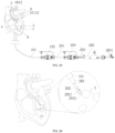
- a transcatheter treatment system which includes the adaptive guiding device 1 according to any of the above embodiments, and further includes a treatment device 2 movably installed in the flexible catheter 101.
- the adaptive guiding device 1 functions to establish a path for intervention from the exterior of the human body into the interior of the human body through the aorta, and the treatment device 2 passes through the aortic arch through the flexible catheter 101.
- the flexible catheter 101 of the adaptive guiding device 1 serves as the outermost sheath (outer sheath in short) of the entire transcatheter treatment system, and usually cooperates with the guide wire to establish the path from the exterior of the human body into the interior of the human body.
- the improved adaptive guiding device 1 By applying the improved adaptive guiding device 1 into the transcatheter treatment system, the guidance efficiency can be improved and the operation safety risks can be reduced.
- the treatment device is selected from at least one of a myocardial injection device, a myocardial ablation device, a valve repair device or a valve replacement device. That is, the adaptive guiding device 1 can be applied in transcatheter endocardium injection systems, transcatheter radiofrequency ablation systems, or heart valve repair systems, to improve guidance efficiency and reduce operation safety risks of the treatment device.
- the treatment device 2 includes a bending sheath 201, an inner sheath 202 and a treatment assembly.
- the bending sheath 201 is movably inserted into the flexible catheter 101 and can be bent in a single direction.
- the inner sheath 202 is movably inserted into the bending sheath 201.
- the treatment assembly is inserted into the inner sheath 202.
- the treatment assembly is selected from at least one of an injection assembly, an ablation assembly, a prosthetic heart valve, an annuloplasty ring, a valve clamping device, a suture, a tissue anchor, or a tissue puncture member.
- the treatment assembly is an injection assembly 203.
- the bending sheath 201 is movably installed in the interior lumen of the flexible catheter 101 of the adaptive guiding device 1 and can be bent unidirectionally.
- the bending sheath 201 cooperates with the adaptive guiding device 1 to deliver the treatment assembly to the predetermined treatment site.
- the inner sheath 202 is movably installed in the interior lumen of the bending sheath 201 to prevent the treatment assembly from scratching the inner wall of the bending sheath 201 and to protect and ensure the movement of the treatment assembly.
- the distal end of the inner sheath 202 is fixedly connected to a limiting element.
- the limiting element can be a metal sleeve 2021.
- the end face of the metal sleeve 2021 is a plane with a certain area, in order to avoid damaging or puncturing the free wall 9 of the left ventricle 4 when it is in contact with the free wall 9.
- the following describes a transcatheter treatment system of the present disclosure, taking the injection assembly 203 as the treatment assembly for example.
- a transcatheter endocardium injection system for injecting hydrogel, cells and other therapeutic agents to diseased ischemic myocardial tissue through a catheter to improve heart function, and can be applied in heart failure treatment.
- the transcatheter endocardium injection system includes an adaptive guiding device 1 and a treatment device 2.
- the adaptive guiding device 1 serves as an outer sheath, and the treatment device 2 is inserted into the adaptive guiding device 1.
- the treatment device 2 includes an injection assembly 203.
- the injection assembly 203 includes an injection channel 2031 and a needle 2032 connected to and communicated with the distal end of the injection channel 2031.
- the needle 2032 is used to penetrate into the myocardial free wall 9 and inject therapeutic agents such as contrast medium, drugs, or hydrogels.
- the end plane of the metal sleeve 2021 at the distal end of the injection channel 2031 defines a through hole for the needle 2032 to pass through.
- the injection channel 2031 includes an inner channel (not shown in the figure) for drug injection and an outer channel for contrast medium injection. The contact of the metal sleeve 2021 with the free wall 9 can be judged by the diffusion of the contrast medium on the free wall 9.
- the treatment device 2 includes a bending sheath 201 inserted in the flexible catheter 101, an inner sheath 202 inserted in the bending sheath 201, and an injection assembly 203 inserted in the inner sheath 202.
- the injection assembly 203 can pass through the inner sheath 202 and then inject therapeutic drugs or other agents into the target area 7 (myocardial tissue).
- FIG. 23 is a further exemplary structural schematic view of the transcatheter endocardium injection system.
- a first adjustment handle 204 and a second adjustment handle 205 are provided corresponding to the bending sheath 201 and the inner sheath 202 respectively. Both the first adjustment handle 204 and the second adjustment handle 205 can be conventional handles.
- the bend direction of the bending sheath 201 is different from the bend direction of the distal section 1013 of the flexible catheter 101 of the adaptive guiding device 1.
- the adjustment range of the orientation of the inner sheath 202 passing through the bending sheath 201 and thus the orientation of the treatment assembly passing through the inner sheath 202 can be enlarged. Therefore, the adjustment flexibility of the output end of the transcatheter treatment system can be improved, which is conducive to guiding the treatment assembly passing through the inner sheath 202 to the target area 7 more accurately, achieving precise guidance.
- the bend direction of the bending sheath 201 is substantially perpendicular to the bend direction of the distal section 1013 of the flexible catheter 101 of the adaptive guiding device 1.
- the bending sheath 201 is arranged in the direction perpendicular to the bend direction of the distal section 1013, in order to improve the adjustment flexibility of the output end of the transcatheter treatment system and guide the treatment assembly passing through the inner sheath 202 to the target area 7 more accurately, achieving precise guidance.
- the distal section 1013 of the outer sheath i.e., the flexible catheter 101 of the adaptive guiding device 1
- the bend direction of the middle sheath i.e., the bending sheath 201
- the different bend directions of the two sheaths cooperating with each other further ensure that the injection assembly is delivered to the desired site for drug injection, so as to achieve good therapeutic effects.
- the delivery path through the femoral artery - aortic arch 3 - left ventricle 4 is taken as an example to illustrate the use method of the transcatheter endocardium injection system according to this embodiment.
- step S1 after puncture of the femoral artery, the adaptive guiding device 1 cooperates with the conventional guide wire to reach the left ventricle 4 through the aortic arch 3 via the femoral artery.
- the flexible catheter 101 of the adaptive guiding device 1 is in the initial state, wherein the distal end of the tube of the adaptive guiding device 1 is centered at a certain distance below the aortic valve 8.
- the treatment device 2 is delivered into the left ventricle 4 along the flexible catheter 101 of the adaptive guiding device 1 until the metal sleeve 2021 at the distal end of the inner sheath 202 is exposed.
- the treatment device 2 is delivered, which is conducive to taking advantage of the pre-shaping of the flexible catheter 101 and avoiding the impact on the pre-shaping if the flexible catheter 101 is delivered synchronously with the treatment device 2.
- the distal end of the flexible catheter 101 does not cross the valve, that is, it stays above the aortic valve 8 and does not extend into the left ventricle.
- step S2 the distal output end of the flexible catheter 101 is adjusted to point between the anterior and posterior papillary muscles 6.
- the bending sheath 201 of the treatment device 2 is pushed forward so that the distal end of the bending sheath 201 is at a certain distance from the distal output end of the flexible catheter 101, and then the distal end of the bending sheath 201 is bent so that the metal sleeve 2021 at the distal end of the inner sheath 202 faces the target area 7 as perpendicularly as possible.
- the inner sheath 202 is pushed further forward until the metal sleeve 2021 contacts the free wall 9 of the target area 7.
- step S3 the needle 2032 at the distal end of the injection channel 2031 penetrates into the free wall 9.
- the contrast medium can be injected into the outer channel of the injection channel 2031 and the diffusion of the contrast medium is observed.
- the therapeutic agent such as hydrogel can be injected into the inner channel to fill the free wall 9 with the drug so as to achieve drug injection.
- step S4 if injection at multiple treatment sites is required, the needle 2032 is withdrawn so that the needle 2032 is retracted into the metal sleeve 2021; and the inner sheath 202 is withdrawn so that the metal sleeve 2021 contacts the distal end of the bending sheath 201.
- the bent configuration of the flexible catheter 101 is kept unchanged, the bending sheath 201 is rotated, and steps S1 to S3 are repeated so as to achieve hydrogel injection at other sites on the same level as the first site.
- the extension of the flexible catheter 101 is increased or decreased, and the bending sheath 201 is rotated so as to select a higher or lower site with respect to the papillary muscle than the first site, and then steps S1 to S3 are repeated to achieve hydrogel injection.
- step S5 after completing the drug injection at all treatment sites, the needle 2032 is withdrawn, the injection channel 2031 is retracted, the bending sheath 201 is released, and the flexible catheter 101 is released. Finally, the treatment device 2 and the flexible catheter 101 are withdrawn.
- a method for controlling a transcatheter endocardium injection system includes a flexible catheter 101, a bending sheath 201 and a needle 2032 slidably arranged sequentially from the outside to the inside, wherein the proximal end of the flexible catheter 101 is controlled by the operating handle 102, the proximal end of the bending sheath 201 is controlled by the first adjustment handle 204, and the proximal end of the needle 2032 is controlled by the second adjustment handle 205.
- the flexible catheter 101 and the bending sheath 201, driven by the corresponding handles, can be rotated and bent respectively.
- the second adjustment handle 205 can be optionally connected to the inner sheath 202, which is located outside the needle 2032 and provided with a metal sleeve 2021 connected to the distal end of the inner sheath 202.
- the transcatheter endocardium injection system can use the relevant components in the above embodiments.
- the target area 7 is in the left ventricle LV.
- the flexible catheter 101 itself can be bent (for example, the flexible catheter 101 can be bent into the flexible catheter 101' as shown in FIG. 25 ), and can be driven by the operating handle 102 to rotate around its own longitudinal axis.
- the bending sheath 201 itself can be bent (for example, the bending sheath 201 can be bent into the bending sheath 201' as shown in FIG. 25 ), and can be driven by the first adjustment handle 204 to rotate around its own longitudinal axis.
- the flexible catheter 101 after being adjusted in place can be kept stationary, and only the orientation and the distal/proximal position of the bending sheath 201 need to be adjusted. This allows for quick adjustment of the orientation and the position of the injection needle in specific cases of multi-point injection, thereby improving the surgical efficiency.
- FIGS. 26 to 28 in the following embodiment, an operation method of the transcatheter treatment system is explained taking injection locations in a multiplerow-and-multiple-column arrangement as an example, that is, a position adjustment method of the needle for continuous injections is explained.
- the arrangement of injection locations in the figures is only an illustration, and can be adjusted in practice according to the area and location of the lesion, wherein the injection locations are the target area 7 and located on the left ventricular wall 206.
- the inner sheath 202 and the metal sleeve 2021 are not shown, and during changing the injection location, the process of withdrawing the needle 2032 before changing the injection location and the process of advancing the needle 2032 after changing the injection location are not shown.
- a method for controlling the transcatheter endocardium injection system includes:
- the spatial offset is realized by using at least one of the following methods so as to adjust the needle position until it corresponds to the next injection location.
- the needle position is adjusted by adjusting the flexible catheter 10 and/or adjusting the bending sheath 201, and specifically, by rotating, bending, moving distally or proximally as a whole.
- the various methods can be combined, and the adjustment magnitude can be controlled based on the modeling in combination with the real-time imaging device.
- the change method of injection location in different situations is explained by referring to the following exemplary operations. The same applies to other situations.
- the flexible catheter remains unchanged and the needle 2032 can be moved from the injection location X1 to the injection location X2 by simply rotating the bending sheath 201 around its longitudinal axis.
- the flexible catheter 101 remains unchanged, and the bending sheath 201 is rotated around its longitudinal axis, so that the needle 2032 moves from the injection location B1 to the injection location B2.
- the bending sheath 201 is bent to move the needle 2032 from the injection location B2 to the injection location B4.
- the flexible catheter 101 remains unchanged and the bending sheath 201 is rotated around its longitudinal axis to move the needle 2032 from the injection location C1 to the injection location C2 or C3.
- the bending sheath 201 remains bent and is retreated along the interventional path, so that the needle 2032 moves from the injection location C3 to the injection location C4.
- the bending sheath 201 is rotated around its longitudinal axis, so that the needle 2032 moves from the injection location C5 to the injection location C6.
- the bending sheath 201 is preferably rotated and bent to reduce axial movement along the interventional path, so as to reduce corresponding potential surgical risks.
- the adaptive guiding device 1 of the present disclosure can be applied in different fields, such as transcatheter radiofrequency ablation systems, heart valve repair systems, etc., to establish lumens from the exterior of the human body to the interior of the human body for interventional devices as needed.
- the exemplary embodiments are not intended to limit the scope of the present disclosure.
- an ablation assembly is used as a treatment assembly.
- the ablation assembly includes an ablation needle 13, an ablation energy generating device 14 connected to and providing ablation energy for the ablation needle 13, and a perfusion device 15 for providing electrolyte solution.
- Other structures of the transcatheter radiofrequency ablation system can refer to the above embodiments where the treatment assembly is an injection assembly, that is, the ablation assembly includes a bending sheath, an inner sheath and an ablation needle.
- the ablation assembly is movably inserted in the adaptive guiding device 1.
- the ablation needle After the ablation needle passes through the inner sheath, it enters the myocardial tissue by puncturing the endocardium, and then the energy generating device provides energy for the ablation needle to perform ablation on the myocardial tissue of the interventricular septum, thereby treating hypertrophic cardiomyopathy (HCM) through minimally invasive intervention.
- HCM hypertrophic cardiomyopathy
- the anchor in the case where the adaptive guiding device 1 is applied in, for example, a transcatheter valve repair system, and an anchor is used as the treatment assembly, the anchor can be implanted in the ventricular wall through a catheter, and the anchor is connected with e-PTFE sutures, wherein one end of the suture is connected to the valve leaflet.
- the suture is used as an artificial chordae to realize the chordae tendineae repair of the valve.
- multiple anchors connected to each other through sutures can be implanted on the ventricular wall in sequence, and then the sutures are tightened to achieve ventricular volume reduction or valvuloplasty, thereby treating valvular regurgitation disease through minimally invasive intervention.
- the adaptive guiding device 1 and the transcatheter treatment system including the adaptive guiding device 1 provided by the present disclosure can better adapt to the complex anatomical morphology of the aortic arch 3, and the structure of the guiding device is simplified, improving the operation safety of the treatment device.
- the guiding device in use does not require a large avoidance space, so that the guiding device has a larger operation and adjustment space and a more convenient initial position for adjustment, and the tissue can be prevented from extending into the avoidance area, thereby reducing blood vessel damage and improving the operation safety of the treatment device.
- the flexible catheter 101 is provided with imaging marks F1 and F2.
- the distance between the imaging marks F1 and F2 on the flexible catheter 101 generally corresponds to the size of the straight segment 10132, for example, in the range of 40 to 80 mm.
- Imaging marks F3 and F4 are provided on the bending sheath 201, and the distance between the imaging marks F3 and F4 on the bending sheath 201 is in the range of 40 to 80 mm.
- the position of the straight segment 10132 and the distal end can be determined.
- the position of the distal end thereof can be determined, further, it can be determined whether the bending sheath 201 has extended out of the most distal end of the flexible catheter 101 by referring to the imaging mark on the most distal end of the flexible catheter 101. At least most of the bending sheath 201 should have extended out of the flexible catheter 101 to facilitate the bending. Otherwise, the flexible catheter 101 will interfere and affect the bending effect.
Landscapes
- Health & Medical Sciences (AREA)
- Life Sciences & Earth Sciences (AREA)
- Engineering & Computer Science (AREA)
- Veterinary Medicine (AREA)
- Biomedical Technology (AREA)
- Heart & Thoracic Surgery (AREA)
- Animal Behavior & Ethology (AREA)
- General Health & Medical Sciences (AREA)
- Public Health (AREA)
- Anesthesiology (AREA)
- Hematology (AREA)
- Pulmonology (AREA)
- Biophysics (AREA)
- Surgery (AREA)
- Medical Informatics (AREA)
- Mechanical Engineering (AREA)
- Physics & Mathematics (AREA)
- Plasma & Fusion (AREA)
- Nuclear Medicine, Radiotherapy & Molecular Imaging (AREA)
- Otolaryngology (AREA)
- Molecular Biology (AREA)
- Dermatology (AREA)
- Cardiology (AREA)
- Media Introduction/Drainage Providing Device (AREA)
- Surgical Instruments (AREA)
Applications Claiming Priority (2)
| Application Number | Priority Date | Filing Date | Title |
|---|---|---|---|
| CN202111679305.6A CN114424972B (zh) | 2021-12-31 | 2021-12-31 | 一种自适应导引装置以及经导管治疗系统 |
| PCT/CN2022/142506 WO2023125572A1 (zh) | 2021-12-31 | 2022-12-27 | 一种自适应导引装置以及经导管治疗系统 |
Publications (2)
| Publication Number | Publication Date |
|---|---|
| EP4458302A1 true EP4458302A1 (de) | 2024-11-06 |
| EP4458302A4 EP4458302A4 (de) | 2025-12-31 |
Family
ID=81310814
Family Applications (1)
| Application Number | Title | Priority Date | Filing Date |
|---|---|---|---|
| EP22914824.2A Pending EP4458302A4 (de) | 2021-12-31 | 2022-12-27 | Adaptive führungsvorrichtung und transkatheterbehandlungssystem |
Country Status (4)
| Country | Link |
|---|---|
| US (1) | US20240350772A1 (de) |
| EP (1) | EP4458302A4 (de) |
| CN (3) | CN118105160A (de) |
| WO (1) | WO2023125572A1 (de) |
Families Citing this family (4)
| Publication number | Priority date | Publication date | Assignee | Title |
|---|---|---|---|---|
| CN118139593A (zh) * | 2021-12-30 | 2024-06-04 | 杭州德柯医疗科技有限公司 | 用于经导管治疗系统的导向管组件、治疗系统和方法 |
| CN118105160A (zh) * | 2021-12-31 | 2024-05-31 | 杭州德柯医疗科技有限公司 | 一种预塑形自适应导引装置以及经导管治疗系统 |
| CN117653323A (zh) * | 2022-08-31 | 2024-03-08 | 杭州诺沁医疗器械有限公司 | 引导组件、消融装置及消融系统 |
| CN116764068B (zh) * | 2023-08-21 | 2023-11-28 | 深圳欢影医疗科技有限公司 | 一种介入类的可调弯导管 |
Family Cites Families (20)
| Publication number | Priority date | Publication date | Assignee | Title |
|---|---|---|---|---|
| US4898577A (en) * | 1988-09-28 | 1990-02-06 | Advanced Cardiovascular Systems, Inc. | Guiding cathether with controllable distal tip |
| US5445625A (en) * | 1991-01-23 | 1995-08-29 | Voda; Jan | Angioplasty guide catheter |
| US5584803A (en) * | 1991-07-16 | 1996-12-17 | Heartport, Inc. | System for cardiac procedures |
| US5766151A (en) * | 1991-07-16 | 1998-06-16 | Heartport, Inc. | Endovascular system for arresting the heart |
| US5195990A (en) * | 1991-09-11 | 1993-03-23 | Novoste Corporation | Coronary catheter |
| WO1996035469A1 (en) * | 1995-05-10 | 1996-11-14 | Cardiogenesis Corporation | System for treating or diagnosing heart tissue |
| US6755812B2 (en) * | 2001-12-11 | 2004-06-29 | Cardiac Pacemakers, Inc. | Deflectable telescoping guide catheter |
| US7998112B2 (en) * | 2003-09-30 | 2011-08-16 | Abbott Cardiovascular Systems Inc. | Deflectable catheter assembly and method of making same |
| US7623899B2 (en) * | 2005-09-16 | 2009-11-24 | Biosense Webster, Inc. | Catheter with flexible pre-shaped tip section |
| WO2010085456A1 (en) * | 2009-01-20 | 2010-07-29 | Guided Delivery Systems Inc. | Anchor deployment devices and related methods |
| US10076327B2 (en) * | 2010-09-14 | 2018-09-18 | Evalve, Inc. | Flexible actuator mandrel for tissue apposition systems |
| US9072872B2 (en) * | 2010-10-29 | 2015-07-07 | Medtronic, Inc. | Telescoping catheter delivery system for left heart endocardial device placement |
| US20120158021A1 (en) * | 2010-12-19 | 2012-06-21 | Mitralign, Inc. | Steerable guide catheter having preformed curved shape |
| JP6050045B2 (ja) * | 2012-07-20 | 2016-12-21 | テルモ株式会社 | 冠動脈用カテーテル |
| CN112190366B (zh) * | 2016-03-24 | 2024-11-05 | 爱德华兹生命科学公司 | 用于假体心脏瓣膜的递送系统 |
| WO2019019937A1 (zh) * | 2017-07-27 | 2019-01-31 | 先健科技(深圳)有限公司 | 可调弯鞘管和医疗器械 |
| WO2020068601A1 (en) | 2018-09-24 | 2020-04-02 | Cottone Robert J | Systems and methods for tissue displacement |
| CN111110985B (zh) * | 2018-10-31 | 2025-04-15 | 杭州唯强医疗科技有限公司 | 调弯手柄及可调弯导管 |
| CN213911909U (zh) * | 2020-11-11 | 2021-08-10 | 广东省人民医院 | 经右桡动脉ⅲ型主动脉弓全脑血管造影导管 |
| CN118105160A (zh) * | 2021-12-31 | 2024-05-31 | 杭州德柯医疗科技有限公司 | 一种预塑形自适应导引装置以及经导管治疗系统 |
-
2021
- 2021-12-31 CN CN202311748944.2A patent/CN118105160A/zh active Pending
- 2021-12-31 CN CN202111679305.6A patent/CN114424972B/zh active Active
-
2022
- 2022-12-27 EP EP22914824.2A patent/EP4458302A4/de active Pending
- 2022-12-27 CN CN202280062791.3A patent/CN118076307A/zh active Pending
- 2022-12-27 WO PCT/CN2022/142506 patent/WO2023125572A1/zh not_active Ceased
-
2024
- 2024-06-28 US US18/757,607 patent/US20240350772A1/en active Pending
Also Published As
| Publication number | Publication date |
|---|---|
| CN118076307A (zh) | 2024-05-24 |
| EP4458302A4 (de) | 2025-12-31 |
| WO2023125572A1 (zh) | 2023-07-06 |
| US20240350772A1 (en) | 2024-10-24 |
| CN118105160A (zh) | 2024-05-31 |
| CN114424972A (zh) | 2022-05-03 |
| CN114424972B (zh) | 2023-12-08 |
Similar Documents
| Publication | Publication Date | Title |
|---|---|---|
| EP4458302A1 (de) | Adaptive führungsvorrichtung und transkatheterbehandlungssystem | |
| US12011551B2 (en) | Fenestration devices, systems, and methods | |
| CN114727836B (zh) | 经导管的医疗植入物递送 | |
| EP2465568B1 (de) | Steuerbarer Führungskatheter mit vorgeformter Kurvenform | |
| US9980812B2 (en) | Mitral valve spacer and system and method for implanting the same | |
| US6830568B1 (en) | Guiding catheter system for ablating heart tissue | |
| JP5964445B2 (ja) | 経皮的な血管内アクセスおよびガイドワイヤ配置用のシステムおよび方法 | |
| JP2009538638A (ja) | 螺旋アンカーを有する弁形成装置およびその使用方法 | |
| JP2008523910A (ja) | 操作可能なガイドカテーテル及びその使用方法 | |
| US20240350767A1 (en) | Guide tube assembly for transcatheter treatment system, treatment system and method | |
| US20210259671A1 (en) | Systems and methods for creating a puncture between aorta and the left atrium | |
| CN118541185A (zh) | 可调节的导引鞘、消融装置、消融系统及心肌消融方法 | |
| CN115645027A (zh) | 远端可调的导管、消融装置及消融系统 | |
| CN121154220B (zh) | 用于卵圆孔未闭介入封堵器导丝的导引系统 | |
| CN222426928U (zh) | 一种可控弯鞘管 | |
| CN118267177A (zh) | 用于心脏介入手术的绕环装置及绕环系统 |
Legal Events
| Date | Code | Title | Description |
|---|---|---|---|
| STAA | Information on the status of an ep patent application or granted ep patent |
Free format text: STATUS: THE INTERNATIONAL PUBLICATION HAS BEEN MADE |
|
| PUAI | Public reference made under article 153(3) epc to a published international application that has entered the european phase |
Free format text: ORIGINAL CODE: 0009012 |
|
| STAA | Information on the status of an ep patent application or granted ep patent |
Free format text: STATUS: REQUEST FOR EXAMINATION WAS MADE |
|
| 17P | Request for examination filed |
Effective date: 20240730 |
|
| AK | Designated contracting states |
Kind code of ref document: A1 Designated state(s): AL AT BE BG CH CY CZ DE DK EE ES FI FR GB GR HR HU IE IS IT LI LT LU LV MC ME MK MT NL NO PL PT RO RS SE SI SK SM TR |
|
| DAV | Request for validation of the european patent (deleted) | ||
| DAX | Request for extension of the european patent (deleted) | ||
| REG | Reference to a national code |
Ref country code: DE Ref legal event code: R079 Free format text: PREVIOUS MAIN CLASS: A61B0018140000 Ipc: A61B0017340000 |
|
| A4 | Supplementary search report drawn up and despatched |
Effective date: 20251202 |
|
| RIC1 | Information provided on ipc code assigned before grant |
Ipc: A61B 17/34 20060101AFI20251126BHEP Ipc: A61M 25/00 20060101ALI20251126BHEP Ipc: A61M 25/06 20060101ALI20251126BHEP |