EP4458301A1 - Nervenablationsvorrichtung - Google Patents
Nervenablationsvorrichtung Download PDFInfo
- Publication number
- EP4458301A1 EP4458301A1 EP22914683.2A EP22914683A EP4458301A1 EP 4458301 A1 EP4458301 A1 EP 4458301A1 EP 22914683 A EP22914683 A EP 22914683A EP 4458301 A1 EP4458301 A1 EP 4458301A1
- Authority
- EP
- European Patent Office
- Prior art keywords
- region
- mounting member
- supporting body
- mesh
- ablation apparatus
- Prior art date
- Legal status (The legal status is an assumption and is not a legal conclusion. Google has not performed a legal analysis and makes no representation as to the accuracy of the status listed.)
- Pending
Links
Images


Classifications
-
- A—HUMAN NECESSITIES
- A61—MEDICAL OR VETERINARY SCIENCE; HYGIENE
- A61B—DIAGNOSIS; SURGERY; IDENTIFICATION
- A61B18/00—Surgical instruments, devices or methods for transferring non-mechanical forms of energy to or from the body
- A61B18/04—Surgical instruments, devices or methods for transferring non-mechanical forms of energy to or from the body by heating
- A61B18/12—Surgical instruments, devices or methods for transferring non-mechanical forms of energy to or from the body by heating by passing a current through the tissue to be heated, e.g. high-frequency current
- A61B18/14—Probes or electrodes therefor
- A61B18/1492—Probes or electrodes therefor having a flexible, catheter-like structure, e.g. for heart ablation
-
- A—HUMAN NECESSITIES
- A61—MEDICAL OR VETERINARY SCIENCE; HYGIENE
- A61B—DIAGNOSIS; SURGERY; IDENTIFICATION
- A61B18/00—Surgical instruments, devices or methods for transferring non-mechanical forms of energy to or from the body
- A61B18/04—Surgical instruments, devices or methods for transferring non-mechanical forms of energy to or from the body by heating
- A61B18/12—Surgical instruments, devices or methods for transferring non-mechanical forms of energy to or from the body by heating by passing a current through the tissue to be heated, e.g. high-frequency current
- A61B18/14—Probes or electrodes therefor
- A61B18/1485—Probes or electrodes therefor having a short rigid shaft for accessing the inner body through natural openings
-
- A—HUMAN NECESSITIES
- A61—MEDICAL OR VETERINARY SCIENCE; HYGIENE
- A61B—DIAGNOSIS; SURGERY; IDENTIFICATION
- A61B18/00—Surgical instruments, devices or methods for transferring non-mechanical forms of energy to or from the body
- A61B2018/00005—Cooling or heating of the probe or tissue immediately surrounding the probe
- A61B2018/00011—Cooling or heating of the probe or tissue immediately surrounding the probe with fluids
- A61B2018/00017—Cooling or heating of the probe or tissue immediately surrounding the probe with fluids with gas
-
- A—HUMAN NECESSITIES
- A61—MEDICAL OR VETERINARY SCIENCE; HYGIENE
- A61B—DIAGNOSIS; SURGERY; IDENTIFICATION
- A61B18/00—Surgical instruments, devices or methods for transferring non-mechanical forms of energy to or from the body
- A61B2018/00005—Cooling or heating of the probe or tissue immediately surrounding the probe
- A61B2018/00011—Cooling or heating of the probe or tissue immediately surrounding the probe with fluids
- A61B2018/00023—Cooling or heating of the probe or tissue immediately surrounding the probe with fluids closed, i.e. without wound contact by the fluid
-
- A—HUMAN NECESSITIES
- A61—MEDICAL OR VETERINARY SCIENCE; HYGIENE
- A61B—DIAGNOSIS; SURGERY; IDENTIFICATION
- A61B18/00—Surgical instruments, devices or methods for transferring non-mechanical forms of energy to or from the body
- A61B2018/00053—Mechanical features of the instrument of device
- A61B2018/00059—Material properties
- A61B2018/00071—Electrical conductivity
- A61B2018/00077—Electrical conductivity high, i.e. electrically conducting
-
- A—HUMAN NECESSITIES
- A61—MEDICAL OR VETERINARY SCIENCE; HYGIENE
- A61B—DIAGNOSIS; SURGERY; IDENTIFICATION
- A61B18/00—Surgical instruments, devices or methods for transferring non-mechanical forms of energy to or from the body
- A61B2018/00053—Mechanical features of the instrument of device
- A61B2018/00059—Material properties
- A61B2018/00089—Thermal conductivity
- A61B2018/00095—Thermal conductivity high, i.e. heat conducting
-
- A—HUMAN NECESSITIES
- A61—MEDICAL OR VETERINARY SCIENCE; HYGIENE
- A61B—DIAGNOSIS; SURGERY; IDENTIFICATION
- A61B18/00—Surgical instruments, devices or methods for transferring non-mechanical forms of energy to or from the body
- A61B2018/00053—Mechanical features of the instrument of device
- A61B2018/0016—Energy applicators arranged in a two- or three dimensional array
-
- A—HUMAN NECESSITIES
- A61—MEDICAL OR VETERINARY SCIENCE; HYGIENE
- A61B—DIAGNOSIS; SURGERY; IDENTIFICATION
- A61B18/00—Surgical instruments, devices or methods for transferring non-mechanical forms of energy to or from the body
- A61B2018/00053—Mechanical features of the instrument of device
- A61B2018/00214—Expandable means emitting energy, e.g. by elements carried thereon
- A61B2018/0022—Balloons
-
- A—HUMAN NECESSITIES
- A61—MEDICAL OR VETERINARY SCIENCE; HYGIENE
- A61B—DIAGNOSIS; SURGERY; IDENTIFICATION
- A61B18/00—Surgical instruments, devices or methods for transferring non-mechanical forms of energy to or from the body
- A61B2018/00053—Mechanical features of the instrument of device
- A61B2018/00214—Expandable means emitting energy, e.g. by elements carried thereon
- A61B2018/00267—Expandable means emitting energy, e.g. by elements carried thereon having a basket shaped structure
-
- A—HUMAN NECESSITIES
- A61—MEDICAL OR VETERINARY SCIENCE; HYGIENE
- A61B—DIAGNOSIS; SURGERY; IDENTIFICATION
- A61B18/00—Surgical instruments, devices or methods for transferring non-mechanical forms of energy to or from the body
- A61B2018/00053—Mechanical features of the instrument of device
- A61B2018/00273—Anchoring means for temporary attachment of a device to tissue
- A61B2018/00279—Anchoring means for temporary attachment of a device to tissue deployable
-
- A—HUMAN NECESSITIES
- A61—MEDICAL OR VETERINARY SCIENCE; HYGIENE
- A61B—DIAGNOSIS; SURGERY; IDENTIFICATION
- A61B18/00—Surgical instruments, devices or methods for transferring non-mechanical forms of energy to or from the body
- A61B2018/00315—Surgical instruments, devices or methods for transferring non-mechanical forms of energy to or from the body for treatment of particular body parts
- A61B2018/00434—Neural system
-
- A—HUMAN NECESSITIES
- A61—MEDICAL OR VETERINARY SCIENCE; HYGIENE
- A61B—DIAGNOSIS; SURGERY; IDENTIFICATION
- A61B18/00—Surgical instruments, devices or methods for transferring non-mechanical forms of energy to or from the body
- A61B2018/00571—Surgical instruments, devices or methods for transferring non-mechanical forms of energy to or from the body for achieving a particular surgical effect
- A61B2018/00577—Ablation
-
- A—HUMAN NECESSITIES
- A61—MEDICAL OR VETERINARY SCIENCE; HYGIENE
- A61B—DIAGNOSIS; SURGERY; IDENTIFICATION
- A61B18/00—Surgical instruments, devices or methods for transferring non-mechanical forms of energy to or from the body
- A61B18/04—Surgical instruments, devices or methods for transferring non-mechanical forms of energy to or from the body by heating
- A61B18/12—Surgical instruments, devices or methods for transferring non-mechanical forms of energy to or from the body by heating by passing a current through the tissue to be heated, e.g. high-frequency current
- A61B18/14—Probes or electrodes therefor
- A61B2018/1405—Electrodes having a specific shape
- A61B2018/1407—Loop
- A61B2018/141—Snare
-
- A—HUMAN NECESSITIES
- A61—MEDICAL OR VETERINARY SCIENCE; HYGIENE
- A61B—DIAGNOSIS; SURGERY; IDENTIFICATION
- A61B18/00—Surgical instruments, devices or methods for transferring non-mechanical forms of energy to or from the body
- A61B18/04—Surgical instruments, devices or methods for transferring non-mechanical forms of energy to or from the body by heating
- A61B18/12—Surgical instruments, devices or methods for transferring non-mechanical forms of energy to or from the body by heating by passing a current through the tissue to be heated, e.g. high-frequency current
- A61B18/14—Probes or electrodes therefor
- A61B2018/1467—Probes or electrodes therefor using more than two electrodes on a single probe
-
- A—HUMAN NECESSITIES
- A61—MEDICAL OR VETERINARY SCIENCE; HYGIENE
- A61B—DIAGNOSIS; SURGERY; IDENTIFICATION
- A61B18/00—Surgical instruments, devices or methods for transferring non-mechanical forms of energy to or from the body
- A61B18/04—Surgical instruments, devices or methods for transferring non-mechanical forms of energy to or from the body by heating
- A61B18/12—Surgical instruments, devices or methods for transferring non-mechanical forms of energy to or from the body by heating by passing a current through the tissue to be heated, e.g. high-frequency current
- A61B18/14—Probes or electrodes therefor
- A61B2018/1497—Electrodes covering only part of the probe circumference
Definitions
- the present invention relates to the field of medical devices, and particularly to a nerve ablation apparatus.
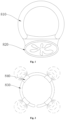
- a cross-section of an airway 810 has an approximately D-shaped profile, and an esophagus 820 generally attaches to a relatively flat side of the airway 810.
- a plurality of electrodes 840 on a nerve ablation apparatus are generally circumferentially distributed on an electrode supporting structure 830. After the electrodes 840 attach to a site to be ablated, the electrodes 840 output radio frequency (RF) energy to destroy nerves on tissues with the electrodes 840 themselves as a center to achieve the effect of blocking nerves.
- RF radio frequency
- the electrodes 840 need to output sufficient RF energy to achieve the ablation of the region away from the electrodes 840, which results in high RF energy in a central region, thereby easily causing burns to the esophagus 820 attached to the airway 810.
- a nerve ablation apparatus including a supporting body and a mounting member, where the mounting member is provided along a circumference of the supporting body and of a mesh structure; the mounting member includes a first region and a second region provided along the circumference of the supporting body and includes the mesh structure formed by a plurality of mesh wires; in the first region, the plurality of mesh wires intersect and at least a portion of the mesh wires are fixedly connected at intersections.
- the mesh wires include woven wires, and the mesh structure is formed by weaving the woven wires.
- the amount of increase of the mesh density in the first region is less than the amount of increase of the mesh density in the second region when the mounting member is subjected to pressure towards an inner side of the supporting body.
- the nerve ablation apparatus further includes a buffer structure; the buffer structure is provided at intersection points of the first region and the second region and is configured to block or weaken the transmission of force between the first region and the second region.
- the buffer structure includes a reinforcing member; the reinforcing member is connected to the supporting body and the mesh wires and extends from the supporting body to the intersection points of the first region and the second region.
- the mesh wire is made of conductive material to make the mounting member form mesh electrodes.
- the stiffness of one end of the supporting body close to the mounting member is less than the stiffness of the other end of the supporting body away from the mounting member.
- the supporting body has a mesh structure, and the area of the smallest mesh of an end portion of the supporting body close to the mounting member is larger than the area of the smallest mesh of an end portion of the supporting body away from the mounting member.
- the cross-sectional area of the supporting body gradually decreases from one end close to the mounting member to one end away from the mounting member.
- At least a portion of the mounting member is bent towards a direction close to the center of the supporting body, and the side wall of the mounting member includes an arcuate curved surface.
- the supporting body includes a disc-shaped woven body formed by weaving at least one woven wire, and the mounting member is provided on a circumferential side wall of the disc-shaped woven body.
- the nerve ablation apparatus further includes a cooling balloon; the cooling balloon is inserted into the supporting body, and after the cooling balloon is inflated, the side wall of the cooling balloon attaches to a side wall of the supporting body.
- heat conduction holes are arranged on the side wall of the supporting body, and after the cooling balloon is inflated, the cooling balloon covers the heat conduction holes.
- the beneficial effects of the nerve ablation apparatus of the present invention are as follows.
- the supporting body When the supporting body is released in an airway, it pushes the mounting member to attach to an inner wall of the airway.
- the first region attaches to a side wall of the airway close to an esophagus, and the second region attaches to a side wall of the airway away from the esophagus.
- the reduction amount of the area of the mesh on the first region is small, and the reduction amount of the area of the mesh on the second region is large, namely, conductive wires on the first region are sparse, and conductive wires on the second region are dense.
- ablation energy emitted by the first region is less than ablation energy emitted by the second region, thereby reducing the burn of the esophagus by the mounting member.
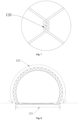
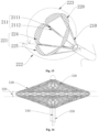
- An embodiment of the present invention provides an ablation apparatus, as shown in Figs. 3 to 9 , including a supporting body 110 and a mounting member 120.
- the mounting member 120 is provided along a circumference of the supporting body 110 and of a mesh structure.
- the mounting member 120 includes a first region 121 and a second region 122, and when the mounting member 120 is compressed by an airway 810, the amount of the mesh density in the first region 121 that increases is less than the amount of the mesh density in the second region 122 that increases.
- the ablation apparatus is configured to output ablation energy at the tissue to be ablated in human body, and the ablation energy ablates nerves in the tissue, thereby achieving the effect of treating a lesion site of human body.
- the ablation apparatus can be used for ablation of airway, heart, aorta, stomach, etc.
- the ablation apparatus is delivered into the airway 810 through a delivery apparatus, and then the ablation apparatus ablates nerves in the tissue of the airway 810, thereby expanding the airway 810 and achieving treatment of a pulmonary disease.
- the supporting body 110 includes a loading state and an expanded state.
- the supporting body 110 is located in the delivery apparatus, the supporting body 110 is in the loading state. At this time, the supporting body 110 is compressed in a sheath of the delivery apparatus to facilitate delivery of the supporting body 110.
- the supporting body 110 is released in the airway 810, the supporting body 110 self- expands, expanding the mounting member 120 to attach to an inner wall of the airway 810.
- the supporting body 110 can be in the shape of a tube, a rod, a disc, or a square and can be formed by cutting memory metal material or by weaving filamentary material.
- the supporting body 110 has a certain elasticity, and when the mounting member 120 is compressed by the airway 810, the supporting body 110 provides an elastic supporting force for the mounting member 120 to ensure a contact area between the mounting member 120 and the inner wall of the airway 810.
- the mounting member 120 can be formed by weaving, by cutting metal material, or be a mesh structure made of conductive material.
- the mounting member 120 is provided around the supporting body 110 and can be wound on the supporting body 110, welded or integrally connected to the supporting body 110.
- An outer side wall of the mounting member 120 has a mesh structure and attaches to the inner wall of the airway 810.
- one axial end of the supporting body 110 is bent radially outward and forms the mounting member 120 by heat setting.
- the mounting member 120 is configured to mount electrodes 840, and the electrodes 840 form ablation energy fields after being mounted on the mounting member 120 to achieve ablation of the tissue of the airway 810.
- the mounting member 120 and the supporting body 110 are both formed by weaving conductive wires, and the conductive wires on the mounting member 120 are exposed to form mesh electrodes 840.
- An outer side wall of the conductive wire on the supporting body 110 is covered with an insulating layer. After energizing the conductive wire, the mounting member 120 forms the mesh electrodes 840 to output RF energy to destroy nerves in the tissue of the airway 810.
- the conductive wire can be a nickel-titanium alloy wire, a stainless-steel wire, or any other wire that can be conductive.
- One end of the conductive wire is connected to an RF (Radio Frequency) energy meter.
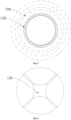
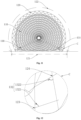
- the RF energy meter provides electric energy for the conductive wire, and the electric energy passes through the supporting body 110 and is transmitted to the mounting member 120 to form an ablation energy field 700.
- the ablation energy field 700 takes the supporting body 110 as a center and then spreads out radially layer by layer from a position where the mounting member 120 attaches to the airway 810.
- the mounting member 120 can be regarded as a point electrode so that a continuous annular ablation energy field 700 can be formed with the mounting member 120 as the center and the position where the mounting member 120 attaches to the airway 810 as a starting point.
- the energy of the mesh electrode is more uniform, and outputted ablation energy is more easily controlled, reducing the probability of the ablation apparatus causing burns to the airway 810.
- the mounting member 120 includes the first region 121 and the second region 122 provided along the circumference of the supporting body 110, and when the mounting member 120 is compressed by the airway 810, the amount of the mesh density in the first region 121 that increases is less than the amount of the mesh density in the second region 122 that increases.
- the mesh density in the embodiment refers to a number of meshes per unit area
- the amount of the mesh density that increases refers to a number of meshes per unit area when the supporting body 110 is not compressed minus a number of meshes per unit area when the supporting body 110 is compressed.
- the first region 121 and the second region 122 are provided along the circumference of the mounting member 120, and the ratio of circumferential lengths of the first region 121 and the second region 122 is: 0.3-1. Specifically, the ratio of the circumferential lengths of the first region 121 and the second region 122 is 0.3, 0.5, 0.6, 0.8, or 1.
- a transparent first fixture in the shape of a rectangular is provided.
- a first lumen structure corresponding to a profile of the mounting member 120 is arranged on the first fixture, and a plurality of measurement square grids having the same area are provided on an outer side wall of the first fixture.
- the side wall of the mounting member 120 attaches to an inner wall of the first lumen structure without an interaction force.
- An electron microscope is used to magnify the first fixture by a certain multiple, and a mesh number t1 in a single measurement square grid is calculated by a mesh method.
- a second fixture corresponding to a cross-section of the airway is provided.
- a second lumen structure corresponding to a profile of the airway is arranged on the second fixture, and a plurality of measurement squares having the same area are provided on an outer side wall of the second fixture.
- the mounting member 120 is released in the second lumen structure and attaches to an inner wall of the second lumen structure.
- the electron microscope is used to magnify the second fixture by a certain multiple, and a mesh number t2 in a single measurement square is calculated by the mesh method. An increasing amount of an area of the mesh is t2-t1.
- the mounting member 120 includes a plurality of mesh wires, which form a mesh structure.
- the mesh wires are formed by weaving woven wires, which can be conductive wires, nickel-titanium alloy wires, or stainless-steel wires.
- woven wires which can be conductive wires, nickel-titanium alloy wires, or stainless-steel wires.
- the conductive wires intersect and are fixedly connected
- the conductive wires intersect and are movably connected.
- the conductive wires intersect to form a grid or mesh, and two intersecting conductive wires are welded or wound at a fixed connection point 126.
- the two intersecting conductive wires are already fixed so that a displacement of two adjacent conductive wires moving towards each other is small or maintained constant. Therefore, an area s1 of the mesh on the first region 121 is constant, or a reduction amount of the area s1 of the mesh is small, and the amount of increase for the mesh density in the first region 121 is small.
- the two intersecting conductive wires attach to each other and may move away from each other or move towards each other.
- the displacement of the two intersecting conductive wires moving towards each other is large. Therefore, the reduction amount of an area s2 of the mesh in the second region 122 is large, namely, the increasing amount of the mesh density in the second region 122 is large.
- the mounting member 120 includes mesh wires formed by cutting metal material.
- the first region 121 includes arcuate mesh wires formed by cutting metal material
- the second region 122 has an arcuate mesh structure formed by weaving the conductive wires.
- the conductive wires on the second region 122 intersect and are movably connected, and two longitudinal ends of the first region 121 and the second region 122 are attached.
- the first region 121 and the second region 122 are compressed by the airway 810, the first region 121 is formed by cutting metal material so that the area s1 of the mesh can be maintained unchanged when the first region 121 is compressed.
- the second region 122 is formed by weaving the conductive wires, and the conductive wires on the second region 122 intersect and are movably connected so that the reduction amount of the area s2 of the mesh in the second region 122 is large when the second region 122 is compressed by the airway 810, thereby realizing the amount of increase for the mesh density in the first region 121 being less than the amount of increase for the mesh density in the second region 122.
- the advantage of this arrangement is that when the supporting body 110 is released in the airway 810, it pushes the mounting member 120 to attach to the inner wall of the airway 810.
- the first region 121 attaches to a side wall of the airway 810 close to the esophagus 820, and the second region 122 attaches to a side wall of the airway 810 away from the esophagus 820.
- the reduction amount of the area of the mesh on the first region 121 is small, and the reduction amount of the area of the mesh on the second region 122 is large, namely, the conductive wires on the first region 121 are sparse, and the conductive wires on the second region 122 are dense.
- ablation energy emitted by the first region 121 is less than ablation energy emitted by the second region 122, thereby reducing the burn of the esophagus 820 by the mounting member 120.
- the stiffness of one end of the supporting body close to the mounting member 120 is less than the stiffness of one end of the supporting body away from the mounting member 120.
- the supporting body 110 has a mesh structure and includes a first end portion 111 and a second end portion 112.
- the first end portion 111 is connected to the mounting member 120, and the area of the smallest mesh on the first end portion 111 is larger than the area of the smallest mesh on the second end portion 112.
- first end portion 111 refers to one end covered by a radial projection of the mounting member 120 on the supporting body 110
- the second end portion 112 refers to the other end of the supporting body 110 away from the mounting member 120.
- the smallest mesh on the first end portion 111 refers to an area S3 of the smallest mesh formed by the conductive wires intersecting on the first end portion 111
- the smallest mesh on the second end portion 112 refers to an area S4 of the smallest mesh formed by the conductive wires intersecting on the second end portion 112.
- the area of the smallest mesh on the first end portion 111 is greater than the area of the smallest mesh on the second end portion 112, namely, the area of any one of the meshes on the first end portion 111 is greater than the area of the mesh on the second end portion 112.
- the area of the mesh on the first end portion 111 is large, namely, the density of the woven wires on the first end portion 111 is low. At this time, the deformation performance of the first end portion 111 is greater than the deformation performance of the second end portion 112.
- the first end portion 111 can be followed the second end portion 112 to deform, avoiding the interference of the supporting body 110 on the deformation of the mounting member 120, making the mounting member 120 more easily adapt to a D-shaped profile of the airway 810, and increasing the adherence of the mounting member 120.
- the area of the mesh on the second end portion 112 is smaller, namely, the density of the conductive wires on the second end portion 112 is low.
- the deformation resistance of the second end portion 112 is greater than the deformation resistance of the first end portion 111 so that the second end portion 112 can provide a supporting force for the first end portion 111 and increase the stability of the delivery and release of the supporting body 110.
- the diameter of the woven wire at the first end portion 111 is smaller than the diameter of the woven wire at the second end portion 112. Since the stiffness of the woven wire with a larger diameter is greater than the stiffness of the woven wire with a smaller diameter, the stiffness at the first end portion 111 is less than the stiffness at the second end portion 112, thereby achieving the arrangement that the stiffness of one end of the supporting body close to the mounting member 120 is less than the stiffness of one end of the supporting body away from the mounting member 120.
- the woven wires at the first end portion 111 intersect and are movably connected, and the woven wires at the second end portion 112 intersect and are fixedly connected. Since the deformation resistance of the fixedly connected woven wires is greater than the deformation resistance of the movably connected woven wires, the stiffness at the first end portion 111 is less than the stiffness at the second end portion 112, thereby achieving the arrangement that the stiffness of one end of the supporting body close to the mounting member 120 is less than the stiffness of one end of the supporting body away from the mounting member 120.
- the supporting body 110 since the stress of the supporting body 110 in the loading state is large, when the supporting body 110 is released in the airway 810, the supporting body 110 tends to be instantaneously expanded and destabilized. At this time, since the second end portion 112 has a higher stiffness, it has a stronger supporting force so that the second end portion 112 can slow down the deformation rate when the first end portion 111 is released, thereby making the first end portion 111 more stable when released.
- a cross-sectional area of the supporting body 110 gradually decreases from the first end portion 111 to the second end portion 112.
- the cross-sectional area of the supporting body 110 refers to the cross-sectional area of the supporting body 110 on a radial plane, and it gradually decreases from the first end portion 111 to the second end portion 112 so that the supporting body 110 defines a truncated cone-shaped structure as a whole.
- the cross-sectional area of the supporting body 110 gradually decreases from the first end portion 111 to the second end portion 112 so that the cross-sectional area of the supporting body 110 at the second end portion 112 is small, thereby reducing the difficulty of the second end portion 112 entering the sheath.
- the deformation of the side of the electrode supporting structure 830 close to the smooth muscle 812 causes excessive deformation of the side of the electrode supporting structure 830 close to the C-shaped region so that a gap s3 is formed between the electrode supporting structure 830 and the inner wall of the airway 810 at a transition region where the C-shaped region connects to the smooth muscle 812, resulting in difficulty in ablating the airway at the gap s3.
- the ablation apparatus further includes a buffer structure 130.
- the buffer structure 130 is connected to the mounting member 120 at connection points of the first region 121 and the second region 122.
- the buffer structure 130 includes reinforcing rods 131.
- the reinforcing rod 131 is welded or inserted on the supporting body 110 and extends to the mounting member 120 along the side wall of the supporting body 110.
- the reinforcing rod 131 forms a deformation-resistant support at the connection point of the first region 121 and the second region 122 and reduces or blocks the transmission of force from the first region 121 to the second region 122.
- the traction of the first region 121 on the second region 122 is blocked or weakened by the reinforcing rod 131 so that the second region 122 is not affected by the deformation of the first region 121, and the second region 122 attaches to the C-shaped profile 811, improving the adherence of the mounting member 120.
- the buffer structure 130 includes reinforcing ribs 132.
- the reinforcing rib 132 is located in the mesh and connected to the woven wires of the mesh intersecting at two circumferential ends of the mounting member 120.
- the mesh in the region where the first region 121 and the second region 122 are connected includes a first intersection point 123 and a second intersection point 124 where the woven wires intersect, and the first intersection point 123 and the second intersection point 124 are provided along the circumference of the mounting member 120.
- the reinforcing rib 132 includes a first reinforcing rib 1321 and a second reinforcing rib 1322.
- first reinforcing rib 1321 Two ends of the first reinforcing rib 1321 are connected to two woven wires on the first intersection point 123, and two ends of the second reinforcing rib 1322 are connected to two woven wires on the second intersection point 124.
- the first reinforcing rib 1321 and the second reinforcing rib 1322 are both in an arcuate structure, and arcuate convex surfaces of the first reinforcing rib 1321 and the second reinforcing rib 1322 are provided opposite to each other.
- a deformation-resistant support may be formed at a position where the first region 121 and the second region 122 are connected, blocking or weakening the transmission of force from the first region 121 to the second region 122 so that the second region 122 is not affected by the deformation of the first region 121, and the second region 122 may attach to the C-shaped profile 811, improving the adherence of the mounting member 120.
- the mounting member 120 further includes third regions 125.
- the third regions 125 are located between the first region 121 and the second region 122 and form free sections to slow down the transmission of force from the first region 121 to the second region 122. It will be appreciated that forming the third region 125 as a free section is one embodiment of the buffer structure 130.
- the free section refers to an unconstrained section, namely, at the third region 125, where the transmission effect of force is low.
- the woven wires at the third region 125 intersect and are movably connected, and the area of the mesh formed by the intersection of the woven wires is much larger than the area of any mesh of the first region 121 and/or the second region 122.
- the density of the woven wires is low, and the transmission effect of force from the first region 121 to the second region 122 is weakened so that the second region 122 is not affected by the deformation of the first region 121, and the second region 122 attaches to the C-shaped profile 811, improving the adherence of the mounting member 120.
- the ratio of the circumferential lengths of the second region 122 and the first region 121 is 1.1-4. Specifically, the ratio of the circumferential lengths of the second region 122 and the first region 121 can be 1.1, 1.5, 2, 3, or 4. Thus, by setting the ratio of the circumferential lengths of the second region 122 and the first region 121, a transition region of the first region 121 and the second region 122 corresponds to a transition region of the C-shaped profile 811 of the airway 810 and the smooth muscle 812, thereby improving the adaptability to the airway 810.
- the mounting member 120 has an arcuate structure, and a convex surface of the arcuate structure is provided toward the side away from the supporting body 110.
- the mounting member 120 is formed by bending one axial end of the supporting body 110 to the outside of the supporting body 110, then bending to the inside of the supporting body 110, and finally by heat setting.
- the mounting member 120 is likely to not attach to a target region.
- a frictional force between the end portion of the mounting member 120 and the airway 810 is large, which may easily rub the airway 810 or cause discomfort to a patient.
- the arcuate structure of the mounting member 120 can attach to the inner wall of the airway 810, the contact area between the arcuate structure and the inner wall of the airway 810 is increased, and the frictional force between the mounting member 120 and the inner wall of the airway 810 is reduced.
- the end portion of the mounting member 120 is provided toward the inner side of the supporting body 110, and during the movement of the mounting member 120, the friction between the end portion of the mounting member 120 and the airway 810 and discomfort to the patient may be prevented.
- the ablation apparatus includes electrodes 840, and the electrodes 840 are provided on the mounting member 120.
- the electrode 840 may be an elongated electrode 840 or a point electrode 840 and is provided on the mounting member 120 along the circumference of the supporting body 110.
- the electrode 840 may be welded or wound on the mounting member 120 and is connected to the RF energy meter.
- the RF energy meter energizes the electrode 840 so that the electrode 840 emits the ablation energy field 700.
- the advantage of this arrangement is that when the mounting member 120 is compressed by the airway 810, the woven wires on the first region 121 intersect and are fixedly connected, and the woven wires on the second region 122 intersect and are movably connected so that the reduction amount of the mesh on the first region 121 is less than the reduction amount of the mesh on the second region 122, namely, the amount of movement of different electrodes 840 on the first region 121 moving towards each other is smaller or unchanged, and the amount of movement of different electrodes 840 on the second region 122 moving towards each other is greater.
- the degree of overlap of the energy fields of the electrodes 840 on the first region 121 is lower than the degree of overlap of the energy fields of the electrodes 840 on the second region 122, namely, the ablation energy emitted by the first region 121 is less than the ablation energy emitted by the second region 122, reducing the burn of the esophagus 820 by the mounting member 120.
- the mounting member 220 includes a plurality of ablation units 221 provided along the circumference of the supporting body 210, and two circumferentially adjacent ablation units 221 are provided at spaced intervals.
- the ablation units 221 are provided on the supporting body 210 and are located on the first region 222 and/or the second region 223.
- the mounting member 220 forms a plurality of ablation units 221 during weaving.
- the ablation units 221 are of a mesh structure with an arcuate edge profile, and two adjacent ablation units 221 have a spacing distance at a portion away from the supporting body 210 to allow a deformation space of the ablation units 221.
- the ablation units 221 may be provided on the first region 222 or the second region 223 at the same time, or only on the first region 222.
- the ablation unit 221 includes a first ablation unit 224 and a second ablation unit 225.
- the first ablation unit 224 is located on the first region 222
- the second ablation unit 225 is located on the second region 223.
- the conductive wires on the first ablation unit 224 intersect and are fixedly connected
- the conductive wires on the second ablation unit 225 intersect and are movably connected.
- Two circumferentially adjacent ablation units 221 have a certain spacing distance.
- the two adjacent ablation units 221 have a spacing distance to block or weaken the transmission of force between the two adjacent ablation units 221.
- the ablation unit 221 is compressed by the smooth muscle 812, on the one hand, the ablation unit 221 does not interfere with the adjacent ablation units 221 and extends to two ends, thereby making the ablation unit 221 more easily attach to the smooth muscle 812; and on the other hand, the ablation unit 221 does not drive the adjacent ablation units 221 to deform.
- the ablation unit 221 on the side away from the smooth muscle 812 is prevented from being pulled and excessively deformed to make it difficult to attach to the C-shaped profile 811, thereby improving the adaptability of the mounting member 220 to the D-shaped profile of the airway.
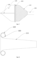
- the supporting body 210 includes a plurality of supporting members 211.
- the plurality of supporting members 211 are provided along the circumference of the mounting member 220 at spaced intervals, and each ablation unit 221 is connected to at least two supporting members 211.
- the supporting body 210 is formed from metal material by laser cutting, and the supporting members 211 are provided along the circumference of the mounting member 220 at equal intervals or at non-equal intervals.
- the embodiment does not limit the number of the supporting members 211.
- the supporting member 211 includes a first supporting arm 2111 and a second supporting arm 2112. One end of the first supporting arm 2111 and one end of the second supporting arm 2112 are connected to form a V-shaped structure, and the other ends of the first supporting arm 2111 and the second supporting arm 2112 are connected to the ablation unit 221. An opening of the V-shaped structure is provided toward the side close to the ablation unit 221. Two ends of each V-shaped structure are connected to two adjacent ablation units 221, respectively, and a plurality of V-shaped structures are provided along the circumference of the mounting member 220.
- the first supporting arm 2111 and the second supporting arm 2112 are connected to form a V-shaped structure.
- the first region 222 is compressed by the airway and deformed, the transmission of force between two adjacent ablation units 221 is interrupted by the gap between the first supporting arm 2111 and the second supporting arm 2112, thereby increasing the adaptability of the mounting member 220 to the inner wall of the D-shaped profile of the airway.
- the supporting member 211 has a rod-like structure.
- Each supporting member 211 is connected to only one ablation unit 221, each ablation unit 221 is connected to at least two adjacent supporting members 211, and the two adjacent supporting members 211 are provided at spaced intervals so that a gap may also be formed between the two adjacent supporting members 211, thereby blocking the transmission of force of the two adjacent ablation units 221 and increasing the adaptability of the mounting member 220 to the D-shaped profile of the airway.
- the spacing distance between two adjacent ablation units 221 is 0.2-1 mm.
- the spacing distance between two adjacent ablation units 221 can be: 0.2mm, 0.4mm, 0.5mm, 0.8mm, or 1mm.
- end portions of the two adjacent ablation units 221 can be attached to form a continuous ablation area in the circumferential direction when the two adjacent ablation units 221 are deformed under pressure.
- the supporting body 310 includes a plurality of woven wires, and the plurality of woven wires are woven to form a disc-shaped woven body 330.
- a circumferential edge 320 of the disc-shaped woven body 330 forms a mounting member, and the first region and the second region are located on the circumferential edge 320 of the disc-shaped woven body 330.
- the woven wire of the disc-shaped woven body 330 is a conductive wire, the circumferential edge 320 of the disc-shaped woven body 330 is exposed, and the exposed portion forms a mesh electrode after being energized.
- an outer side wall of the disc-shaped woven body 330 is covered with an insulating layer, or the woven wire of the disc-shaped woven body 330 is non-conductive material.
- the electrode is provided on the outer side wall of the disc-shaped woven body 330 to form a mounting member.
- the woven wires intersect and are fixedly connected, and at the second region, the woven wires intersect and are movably connected.
- the first region and the second region are provided along the circumference of the disc-shaped woven body 330, and the ratio of lengths of the first region and the second region is similar to that of embodiment 1, which will not be described in detail.
- the disc-shaped woven body 330 is formed by weaving the woven wires through the supporting body 310 and has a good radial supporting force.
- the supporting body 310 provides a sufficient supporting force to make the mounting member attach to the inner wall of the airway.
- the ablation apparatus includes an adjusting member 340.
- One end of the adjusting member 340 is connected to one axial end of the disc-shaped woven body 330, and the other end of the adjusting member 340 passes through a sleeve 350.
- the adjusting member 340 is configured to adjust a diameter of the disc-shaped woven body 330.
- two axial ends of the disc-shaped woven body 330 extend to an axially outer side of the disc-shaped woven body 330 to allow a deformation space for diameter adjustment of the disc-shaped woven body 330.
- One end of the adjusting member 340 is threadably connected or welded to one axial end of the disc-shaped woven body 330, and the other end of the adjusting member 340 passes through the sleeve 350.
- the adjusting member 340 when it is necessary to increase the diameter of the disc-shaped woven body 330, the adjusting member 340 is pulled to move the two axial ends of the disc-shaped woven body 330 towards each other, thereby increasing the diameter of the disc-shaped woven body 330; when it is necessary to increase the diameter of the disc-shaped woven body 330, the adjusting member 340 is pushed to move the two axial ends of the disc-shaped woven body 330 away from each other, thereby reducing the diameter of the disc-shaped woven body 330.
- the advantage of this arrangement is that when the supporting body 310 deviates from the target position after being released in the airway, the diameter of the disc-shaped woven body 330 is adjusted by the adjusting member 340 so that the diameter of the disc-shaped woven body 330 is reduced to adjust a position of the disc-shaped woven body 330 in the airway, thereby reducing the difficulty in adjusting the position of the supporting body 310 in the airway.
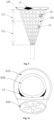
- the ablation apparatus includes a cooling balloon 430.
- the cooling balloon 430 is inserted into a supporting body 410, and when the cooling balloon 430 is inflated, it at least partially covers meshes on a mounting member 420.
- the cooling balloon 430 is configured to accommodate a cooling medium.
- One end of a delivery channel 440 is located in the balloon, and the other end of the delivery channel 440 passes through a sleeve 450.
- the cooling medium may be inputted into the balloon through a conduit to achieve cooling of the electrode and the site to be ablated.
- the cooling medium may be a gaseous cooling medium or a liquid cooling medium.
- the cooling medium may be at least one of CO2 gas flow, physiological saline, or purified water.
- Side walls of the supporting body 410 and the mounting member 420 are of a mesh structure, and meshes on the mesh structure constitute heat conduction holes.
- the cooling medium is inputted into the cooling balloon 430 to inflate the balloon.
- the cooling balloon 430 After the cooling balloon 430 is inflated, it attaches to the side walls of the supporting body 410 and the mounting member 420 and covers the meshes of the supporting body 410 and the mounting member 420 so that a side wall of the cooling balloon 430 attaches to the inner wall of the airway.
- the heat on the inner wall of the airway can be transmitted to the cooling balloon 430 through the heat conduction holes, increasing the heat conduction efficiency and improving the cooling effect of the balloon.
- the cooling medium in the balloon is withdrawn to deflate the balloon, and the balloon and supporting body 410 are withdrawn.
- the cooling balloon 430 when the cooling balloon 430 is inflated, the cooling balloon 430 is inserted into the supporting body 410, and the side wall of the cooling balloon 430 covers the meshes of the supporting body 410 and the mounting member 420 so that the side wall of the cooling balloon 430 attaches to the inner wall of the airway, facilitating the cooling of the electrode and the inner wall of the airway, and avoiding the burn of the inner wall of the airway due to excessive ablation temperature.
- the ablation apparatus includes a cooling conduit 460.
- the cooling conduit 460 is provided around the supporting body 410 and is located on an inner side of the mounting member 420.
- An outer wall of the cooling conduit 460 attaches to the inner wall of the mounting member 420.
- Injection holes are arranged on the cooling conduit 460, and positions of the injection holes correspond to positions of the meshes on the mounting member 420.
- the cooling medium passes through the injection holes and the meshes on the mounting member 420 to be injected to the inner wall of the airway, thereby facilitating the cooling of the inner wall of the airway, and avoiding the burn of the inner wall of the airway due to excessive ablation temperature.
Landscapes
- Health & Medical Sciences (AREA)
- Surgery (AREA)
- Engineering & Computer Science (AREA)
- Life Sciences & Earth Sciences (AREA)
- Biomedical Technology (AREA)
- Molecular Biology (AREA)
- Nuclear Medicine, Radiotherapy & Molecular Imaging (AREA)
- Plasma & Fusion (AREA)
- Physics & Mathematics (AREA)
- Heart & Thoracic Surgery (AREA)
- Medical Informatics (AREA)
- Otolaryngology (AREA)
- Animal Behavior & Ethology (AREA)
- General Health & Medical Sciences (AREA)
- Public Health (AREA)
- Veterinary Medicine (AREA)
- Cardiology (AREA)
- Surgical Instruments (AREA)
Applications Claiming Priority (2)
| Application Number | Priority Date | Filing Date | Title |
|---|---|---|---|
| CN202111677021.3A CN116407263A (zh) | 2021-12-31 | 2021-12-31 | 神经消融装置 |
| PCT/CN2022/141979 WO2023125429A1 (zh) | 2021-12-31 | 2022-12-26 | 神经消融装置 |
Publications (2)
| Publication Number | Publication Date |
|---|---|
| EP4458301A1 true EP4458301A1 (de) | 2024-11-06 |
| EP4458301A4 EP4458301A4 (de) | 2025-12-10 |
Family
ID=86997829
Family Applications (1)
| Application Number | Title | Priority Date | Filing Date |
|---|---|---|---|
| EP22914683.2A Pending EP4458301A4 (de) | 2021-12-31 | 2022-12-26 | Nervenablationsvorrichtung |
Country Status (4)
| Country | Link |
|---|---|
| US (1) | US20250057583A1 (de) |
| EP (1) | EP4458301A4 (de) |
| CN (1) | CN116407263A (de) |
| WO (1) | WO2023125429A1 (de) |
Families Citing this family (1)
| Publication number | Priority date | Publication date | Assignee | Title |
|---|---|---|---|---|
| WO2025139654A1 (zh) * | 2023-12-26 | 2025-07-03 | 深圳市先健呼吸科技有限公司 | 消融装置 |
Family Cites Families (9)
| Publication number | Priority date | Publication date | Assignee | Title |
|---|---|---|---|---|
| CN201223445Y (zh) * | 2008-06-23 | 2009-04-22 | 北京有色金属研究总院 | 一种射频消融导管 |
| EP2929852A1 (de) * | 2010-04-06 | 2015-10-14 | Holaira, Inc. | System zur lungenbehandlung |
| US20120101413A1 (en) * | 2010-10-20 | 2012-04-26 | Medtronic Ardian Luxembourg S.a.r.I. | Catheter apparatuses having expandable mesh structures for renal neuromodulation and associated systems and methods |
| CN103584909B (zh) * | 2012-08-17 | 2016-01-27 | 王涛 | 开放式网状射频消融电极 |
| US20150105772A1 (en) * | 2013-10-14 | 2015-04-16 | Boston Scientific Scimed, Inc. | Devices and methods for nerve modulation |
| CN109199581A (zh) * | 2014-08-05 | 2019-01-15 | 上海魅丽纬叶医疗科技有限公司 | 具有网管状支架结构的射频消融导管及其设备 |
| US20180056074A1 (en) * | 2016-08-25 | 2018-03-01 | Boston Scientific Scimed, Inc. | Systems and methods for reversible nerve block to relieve disease symptoms |
| CN113116448A (zh) * | 2019-12-31 | 2021-07-16 | 杭州诺芮医疗科技有限公司 | 改进安全性的左心耳消融封堵装置 |
| CN111568539A (zh) * | 2020-06-16 | 2020-08-25 | 北京奇伦天佑创业投资有限公司 | 一种射频消融用可解脱支架电极导管 |
-
2021
- 2021-12-31 CN CN202111677021.3A patent/CN116407263A/zh active Pending
-
2022
- 2022-12-26 WO PCT/CN2022/141979 patent/WO2023125429A1/zh not_active Ceased
- 2022-12-26 EP EP22914683.2A patent/EP4458301A4/de active Pending
- 2022-12-26 US US18/725,037 patent/US20250057583A1/en active Pending
Also Published As
| Publication number | Publication date |
|---|---|
| EP4458301A4 (de) | 2025-12-10 |
| US20250057583A1 (en) | 2025-02-20 |
| WO2023125429A1 (zh) | 2023-07-06 |
| CN116407263A (zh) | 2023-07-11 |
Similar Documents
| Publication | Publication Date | Title |
|---|---|---|
| CN112168286B (zh) | 取栓支架、取栓装置及取栓系统 | |
| CN110731843B (zh) | 一种血管支架 | |
| CN107049420B (zh) | 一种取栓支架及血栓取出装置 | |
| EP3003193B1 (de) | Geräte zur energieabgabe | |
| CN112168285B (zh) | 取栓装置及取栓系统 | |
| CN114404035B (zh) | 消融装置 | |
| US20170224415A1 (en) | Radiofrequency ablation catheter having meshed tubular stent structure and an apparatus thereof | |
| US9320502B2 (en) | Cytology balloon | |
| CN112168284B (zh) | 取栓支架、取栓装置及取栓系统 | |
| KR101415902B1 (ko) | 소작 겸용 스텐트 시술장치 | |
| EP4458301A1 (de) | Nervenablationsvorrichtung | |
| CN110721012B (zh) | 一种分段处标记支架 | |
| CN115517759A (zh) | 一种医用消融导管、消融系统及使用方法 | |
| CN219109865U (zh) | 切割管、鞘管及输送系统 | |
| EP3965677A1 (de) | Abbildungs- und ablationskatheter mit mehreren schleifensegmenten | |
| CN113855351B (zh) | 颅内取栓支架 | |
| US11033294B2 (en) | Method of treatment for aortic dissection | |
| WO2022171141A1 (zh) | 消融系统 | |
| CN213821612U (zh) | 取栓支架、取栓装置及取栓系统 | |
| US20250114139A1 (en) | Ablation Apparatus | |
| WO2023125647A1 (zh) | 消融装置 | |
| CN111821016A (zh) | 电刀、具有其的治疗设备及控制方法和装置 | |
| CN112120828B (zh) | 一种腔静脉滤器 | |
| CN113208702A (zh) | 切割丝固定结构及切割球囊导管 | |
| CN209405031U (zh) | 一种用于近分叉部位病变的支架 |
Legal Events
| Date | Code | Title | Description |
|---|---|---|---|
| STAA | Information on the status of an ep patent application or granted ep patent |
Free format text: STATUS: THE INTERNATIONAL PUBLICATION HAS BEEN MADE |
|
| PUAI | Public reference made under article 153(3) epc to a published international application that has entered the european phase |
Free format text: ORIGINAL CODE: 0009012 |
|
| STAA | Information on the status of an ep patent application or granted ep patent |
Free format text: STATUS: REQUEST FOR EXAMINATION WAS MADE |
|
| 17P | Request for examination filed |
Effective date: 20240730 |
|
| AK | Designated contracting states |
Kind code of ref document: A1 Designated state(s): AL AT BE BG CH CY CZ DE DK EE ES FI FR GB GR HR HU IE IS IT LI LT LU LV MC ME MK MT NL NO PL PT RO RS SE SI SK SM TR |
|
| DAV | Request for validation of the european patent (deleted) | ||
| DAX | Request for extension of the european patent (deleted) | ||
| A4 | Supplementary search report drawn up and despatched |
Effective date: 20251107 |
|
| RIC1 | Information provided on ipc code assigned before grant |
Ipc: A61B 18/14 20060101AFI20251103BHEP Ipc: A61B 18/12 20060101ALI20251103BHEP Ipc: A61B 18/00 20060101ALN20251103BHEP |