EP4455086A1 - Graphitierungsofen mit einem ascheauslass - Google Patents
Graphitierungsofen mit einem ascheauslass Download PDFInfo
- Publication number
- EP4455086A1 EP4455086A1 EP23170110.3A EP23170110A EP4455086A1 EP 4455086 A1 EP4455086 A1 EP 4455086A1 EP 23170110 A EP23170110 A EP 23170110A EP 4455086 A1 EP4455086 A1 EP 4455086A1
- Authority
- EP
- European Patent Office
- Prior art keywords
- channel
- ash
- gas
- graphitization furnace
- outlet
- Prior art date
- Legal status (The legal status is an assumption and is not a legal conclusion. Google has not performed a legal analysis and makes no representation as to the accuracy of the status listed.)
- Withdrawn
Links
Images


Classifications
-
- F—MECHANICAL ENGINEERING; LIGHTING; HEATING; WEAPONS; BLASTING
- F27—FURNACES; KILNS; OVENS; RETORTS
- F27B—FURNACES, KILNS, OVENS OR RETORTS IN GENERAL; OPEN SINTERING OR LIKE APPARATUS
- F27B9/00—Furnaces through which the charge is moved mechanically, e.g. of tunnel type; Similar furnaces in which the charge moves by gravity
- F27B9/28—Furnaces through which the charge is moved mechanically, e.g. of tunnel type; Similar furnaces in which the charge moves by gravity for treating continuous lengths of work
-
- C—CHEMISTRY; METALLURGY
- C01—INORGANIC CHEMISTRY
- C01B—NON-METALLIC ELEMENTS; COMPOUNDS THEREOF; METALLOIDS OR COMPOUNDS THEREOF NOT COVERED BY SUBCLASS C01C
- C01B32/00—Carbon; Compounds thereof
- C01B32/05—Preparation or purification of carbon not covered by groups C01B32/15, C01B32/20, C01B32/25, C01B32/30
-
- C—CHEMISTRY; METALLURGY
- C01—INORGANIC CHEMISTRY
- C01B—NON-METALLIC ELEMENTS; COMPOUNDS THEREOF; METALLOIDS OR COMPOUNDS THEREOF NOT COVERED BY SUBCLASS C01C
- C01B32/00—Carbon; Compounds thereof
- C01B32/20—Graphite
- C01B32/205—Preparation
-
- F—MECHANICAL ENGINEERING; LIGHTING; HEATING; WEAPONS; BLASTING
- F27—FURNACES; KILNS; OVENS; RETORTS
- F27B—FURNACES, KILNS, OVENS OR RETORTS IN GENERAL; OPEN SINTERING OR LIKE APPARATUS
- F27B1/00—Shaft or like vertical or substantially vertical furnaces
- F27B1/10—Details, accessories or equipment specially adapted for furnaces of these types
-
- F—MECHANICAL ENGINEERING; LIGHTING; HEATING; WEAPONS; BLASTING
- F27—FURNACES; KILNS; OVENS; RETORTS
- F27B—FURNACES, KILNS, OVENS OR RETORTS IN GENERAL; OPEN SINTERING OR LIKE APPARATUS
- F27B9/00—Furnaces through which the charge is moved mechanically, e.g. of tunnel type; Similar furnaces in which the charge moves by gravity
- F27B9/30—Details, accessories or equipment specially adapted for furnaces of these types
- F27B9/32—Casings
Definitions
- the present invention relates to the field of graphitization furnaces. More specifically, the present invention relates to graphitization furnaces comprising an ash collection chamber.
- the most common commercially used anode material in lithium-ion batteries is graphite.
- the graphite can be lithiated to the state of LiC 6 , which correlates to a theoretical maximal capacity of 372 mAh/g.
- Artificial graphite may be produced by heating carbonaceous starting materials, such as coke and/or pitch, to temperatures of about 3000 °C under exclusion of oxygen.
- the heating may be performed in batch or continuous furnaces.
- a powdery or granulated carbonaceous material may be conveyed along a heated channel between a raw material inlet and a product outlet, transitioning to graphite while being conveyed.
- the carbonaceous starting materials may still comprise impurities.
- these impurities may evaporate or outgas from the carbonaceous material during graphitization as e.g. volatile elements, carbides or oxides.
- the impurities and the generated volatiles may also be referred to as ash.
- the ash To attain a high-quality graphite from the graphitization process, the ash needs to be removed from the carbonaceous material and the reaction zone of the furnace. Additionally, the ash needs to be removed from the furnace in a controlled manner to prevent its undesired condensation on parts of the furnace, for example within a flue duct.
- the present disclosure aims to address the aforementioned issues in graphitization furnaces.
- the present disclosure relates to a graphitization furnace comprising a raw material inlet, a product outlet and a channel 100 connecting the raw material inlet and the product outlet.
- the graphitization furnace further comprises an ash outlet 110 in gaseous communication with the channel 100, wherein the ash outlet 110 comprises an ash collection chamber 120 comprising a hatch 160 and a high surface area body 130 removably disposed within the ash collection chamber 120, and/or a cooling means 140.
- the graphitization furnace may be a continuous graphitization furnace, in particular a vertical continuous graphitization furnace.
- the ash outlet may be provided adjacent to and in gaseous communication with the channel.
- the ash outlet may comprise a gas inlet, in particular wherein the gas inlet may be configured to allow gas from the channel to enter into the ash outlet.
- the gas inlet may be disposed at an upstream end of the ash outlet and/or the gas outlet may be disposed at a downstream end of the ash outlet.
- the channel may comprise a channel heating zone, a channel high temperature reaction zone and a channel cooling zone, wherein the ash outlet is in gaseous communication with the channel high temperature reaction zone.
- the graphitization furnace may comprise at least one gas injection port.
- the channel may be provided with at least one gas injection port connected to a purge gas pump and/or pressure regulator, in particular wherein the purge gas pump and/or pressure regulator is/are configured to maintain a pressure above the ambient pressure in the graphitization furnace.
- the at least one gas injection port may be connected to a heat exchanger configured to preheat the injected gas.
- the ash outlet may comprise a gas outlet.
- the high surface area body may be a felt, in particular a carbon or graphite felt.
- the high surface area body may be at least partially encased in a cartridge.
- the ash outlet may comprise a cooling zone, more specifically the cooling zone may be disposed surrounding at least part of the removable high surface area body, and/or the cooling zone may be disposed between an inlet of the ash collection chamber and the channel, and/or the cooling zone may be disposed between the ash collection chamber and the gas outlet.
- the cooling zone may comprise the cooling means.
- the cooling means may be configured to cool at least 70 wt.-%, more specifically at least 80 wt.-% and in particular at least 90 wt.-% of the volatilized ash to a temperature below the respective solidification/condensation temperatures.
- the cooling means may be configured to cool the volatile/gas stream to temperatures below 2000 °C, more specifically to below 1800°C, even more specifically to below 1700°C and in particular to below 1500°C.
- the ash outlet may comprise the cooling means, more specifically wherein the cooling means may be provided closer to the gas inlet than the high surface area body.
- the cooling means may be provided further away from the gas inlet than the high surface area body.
- the cooling means extends along the whole ash collection chamber.
- the graphitization furnace may comprise an ash collection container.
- the cooling means may comprise a cold trap.
- the channel may be surrounded by an isolation structure, wherein the ash outlet may be disposed within the isolation structure.
- the channel may be gas permeable, more specifically the channel may comprise gas permeable graphite, in particular the channel may comprise porous graphite with a gas permeability of at least 0,3 cm 2 /s (measured according to DIN 51935:2019-07).
- the isolation structure may be gas impermeable, more specifically the isolation structure may comprise gas impermeable graphite, in particular the isolation structure may comprise Gas impermeable with a gas permeability of less than 0,3 cm 2 /s (measured according to DIN 51935:2019-07).
- the ash outlet may comprise a means of gaseous communication between the ash outlet and the channel, in particular the means of gaseous communication may be a pipe penetrating an isolation structure which surrounds the channel.
- a gas permeable material may be disposed between the channel and the isolation structure, more specifically a particulate carbonaceous material and in particular pearled soot, particulate graphite, particulate coke or carbon black.
- the furnace may comprise a second ash collection chamber in gaseous communication with the channel comprising a second hatch and a second high surface area body removably disposed within the second ash collection chamber, and/or a second cooling means.
- the ash collection chamber and the second ash collection chamber may be arranged such that they may be operated in parallel operation and wherein the furnace further contains one or more valve means to control the gaseous communication of the respective ash collection chamber with the channel.
- the present disclosure relates to a method of using a graphitization furnace according to any preceding embodiment for preparing graphite from carbonaceous material.
- the most common commercially used anode material in lithium-ion batteries is graphite.
- the graphite can be lithiated to the state of LiC 6 , which correlates to a theoretical maximal capacity of 372 mAh/g.
- Artificial graphite may be produced by heating carbonaceous starting materials, such as coke and/or pitch, to temperatures of about 3000 °C under exclusion of oxygen.
- the heating may be performed in batch or continuous furnaces.
- powdery or granulated carbonaceous material may be conveyed along a heated channel between a raw material inlet and a product outlet, transitioning to graphite while being conveyed.
- the carbonaceous starting materials may still comprise impurities.
- impurities also referred to as ash
- coke may comprise up to 20 wt.-% of ash.
- the ash needs to be removed from the carbonaceous material.
- the impurities may evaporate at different typical temperature levels, depending on the nature of the impurities, during the process of heating the starting materials up to the maximum temperature, up to above 3000°C.
- the ash may partly or completely condensate and/or react on cooler parts of the graphitization furnace.
- the ash may condensate in gas outlets, e.g.
- the condensing ash may also react upon condensation to form e.g. carbide compounds with carbon or graphite materials in the furnace that are exposed to the ash vapor. Clogging of gas outlets may result in overpressure within the furnace, which may necessitate a shutdown of the graphitization furnace. Carbide formation may lead to destruction of affected parts of the furnace.
- the ash typically comprises inorganic impurities.
- these inorganic impurities may evaporate, decompose, or react otherwise to volatile species or may be converted in-situ in volatile species such as carbides, elemental vapor, etc.
- the impurities may also be actively converted into more volatile substances by adding purge gases.
- the present disclosure contemplates facilitating removal of these volatiles by creating a pressure differential in the furnace.
- the pressure differential is created by providing a site of preferential deposition for the volatiles outside of the primary reaction zone of furnace.
- the site of preferential deposition creates a pressure differential which drives the volatiles away from the site of their generation, i.e. the carbonaceous material undergoing graphitization.
- a removable high surface area body may be used as an effective means for providing a site of preferential deposition, while preventing excessive loss of thermal energy from the graphitization furnace.
- a cooling means may be used as a further effective means for providing a site of preferential deposition and may be used to solidify gaseous ash from a gas stream, again preventing excessive loss of thermal energy from the graphitization furnace.
- the aforementioned differential pressure-driven removal of volatiles may further be facilitated by providing a gas stream to the carbonaceous material which drives the volatiles towards the site of preferential deposition and/or by providing a vacuum which pulls the volatiles towards the site of preferential deposition.
- the present disclosure relates to a graphitization furnace comprising a raw material inlet, a product outlet and a channel 100 connecting the raw material inlet and the product outlet.
- the graphitization furnace further comprises an ash outlet 110 in gaseous communication with the channel 100, wherein the ash outlet 110 comprises an ash collection chamber 120.
- the ash collection chamber 120 comprises a hatch 160.
- the ash collection chamber 120 comprises a high surface area body 130 removably disposed within the ash collection chamber 120.
- the ash collection chamber 120 comprises a cooling means 140.
- Fig. 1 shows a section of an exemplary schematic graphitization furnace according to the first aspect.
- the graphitization furnace is a vertical graphitization furnace. Carbonaceous material is supplied to the channel 100 via the raw material inlet and converted to graphite while passing through channel 100. Graphite is then discharged through the product outlet.
- the graphitization furnace further comprises an ash outlet 110.
- the ash outlet 110 is provided adjacent to (i.e. external to channel 100) and in gaseous communication with the channel 100.
- the ash outlet 110 is provided adjacent to (i.e. external to channel 100) and in gaseous communication with the channel 100. In some embodiments, e.g.
- the ash outlet 110 and the channel 100 do not form an integral or unitary body or apparatus, the ash outlet 110 comprises a means of gaseous communication between the ash outlet 110 and the channel 100.
- the means of gaseous communication may be provided in the form of a pipe penetrating an isolation structure 200 which surrounds the channel 100, but other configurations (e.g. as discussed later on with respect to Fig. 2 ) are also possible.
- channel 100 may comprise a channel heating zone, a channel high temperature reaction zone and a channel cooling zone.
- the heating zone may be characterized by the temperature of the carbonaceous material increasing in flow direction when the graphitization furnace is used.
- the channel high temperature reaction zone may be characterized by the carbonaceous material having a temperature of at least 80% of the maximum temperature achieved in the graphitization furnace.
- the channel cooling zone may be characterized by the temperature of the carbonaceous material decreasing in flow direction when the graphitization furnace is used. It may be particularly advantageous that the ash outlet 110 is in gaseous communication with the channel high temperature reaction zone of channel 100 since this may help in minimizing the undesirable deposition of ash in other parts of the furnace.
- the graphitization furnace comprises at least one gas injection port (not shown in Fig. 1 ).
- the gas injection port may be configured to dispense inert gases (such as helium or argon) and/or purge gases (such as a gas comprising halogens). It may be particularly advantageous that the gas injection port is located closer to the product outlet than the opening where the ash outlet 110 is in gaseous communication with the channel 100.
- the inert gases or purge gases injected into channel 100 may facilitate driving the volatiles towards ash outlet 110 and away from the product outlet, to provide a purer product with a lower consumption of gas.
- the gas injection port is located at about the same or at about substantially the same level (relative to the raw material inlet and the product outlet) as the opening where ash outlet 110 is in gaseous communication with the channel 100.
- it is also provided on the opposite side of channel 100. However, this is not strictly necessary, in particular if a plurality of gas injection ports is used which are arranged circumferentially around channel 100.
- the channel 100 may be provided with at least one gas injection port connected to a purge gas pump and/or pressure regulator, in particular wherein the purge gas pump and/or pressure regulator is/are configured to maintain a pressure above the ambient pressure in the graphitization furnace.
- the at least one gas injection port is further connected to a heat exchanger configured to preheat the injected gas. From a standpoint of energy efficiency, it may be particularly advantageous that the heat exchanger is configured to draw heat from gas having left channel 100 towards ash outlet 110 or to draw heat from the channel cooling zone of channel 100.
- the graphitization furnace may be a continuous graphitization furnace, in particular a vertical continuous graphitization furnace.
- the provision of an ash outlet 110 in a continuous graphitization furnace may be particularly advantageous, as it may allow for continued removal of ash from the graphitization furnace, which may otherwise require frequent shutdowns of the oven to remove the ash to prevent safety hazards.
- the portion of the ash outlet 110 connecting it to the channel 100 may be referred to as a gas inlet 210.
- the gas inlet 210 may be configured to allow gas from the channel 100 to enter into the ash outlet 110.
- the gas inlet 210 may be disposed at an upstream end of the ash outlet 110 and/or the gas outlet 150 may be disposed at a downstream end of the ash outlet.
- the terms upstream and downstream refer to the direction of gas flow within the ash outlet 110.
- the ash outlet 110 comprises an ash collection chamber 120 and a high surface area body 130 removably disposed therein.
- the high surface area body 130 may - due to its large surface area - act as a site of preferential deposition even in the absence of a distinct cooling means, however, it may be particularly advantageous to operate the high surface area body 130 in combination with a cooling means as described in more detail below.
- the ash collection chamber 120 may be a section of a tube of the ash outlet 110, wherein the ash is configured to solidify.
- the ash collection chamber 120 may also be a section with a differing diameter or separate structure wherethrough the gas stream is directed.
- the ash outlet 110 may comprise a gas outlet 150 which may be used to process remaining gasses further downstream.
- the high surface area body 130 may be placed between the gas inlet 210 and the gas outlet 150 such that the ash from the gas stream may solidify on the high surface area body 130, before the gas stream escapes through the gas outlet 150.
- the ash collection chamber 120 comprises a hatch 160.
- the hatch 160 may be opened to remove or replace the high surface area body 130.
- the specific form of the hatch is not particularly limited as long as it allows access to the high surface area body 130. It can be as simple as a hatch door or more elaborate such as an inert gas lock.
- the high surface area body 130 may be a non-woven material such as a felt, more specifically a carbonaceous felt, in particular a graphite felt or a carbon felt.
- Graphite felts and carbon felts may have a high surface area. Additionally, graphite felts and carbon felts may exhibit a low thermal conductivity and high thermal resistance. Graphite felts may exhibit improved mechanical properties compared to non-graphite felts, which may ensure structural integrity of the felt when removing it from the ash collection chamber 120. However, carbon felts may be cheaper and exhibit a lower thermal conductivity compared to graphite felts. Additionally, carbon felts may be graphitized while collecting the ash. As graphite felts and carbon felts exhibit high chemical resistance, they may be reused after (chemically and/or physically) removing the ash.
- the high surface area body may comprise or consist of a particulate carbonaceous material, more specifically particulate graphite, particulate coke, pearled soot.
- the high surface are body may comprise or consist of carbon black.
- the high surface area body 130 may be a body comprising a plurality of lamella or rips, in particular a plurality of lamella or rips which form a tortuous path for the gas stream.
- the high surface area body 130 and the cooling means 140 may be the same structure, in particular the high surface area body 130 may be a first side of a heat exchanger and the cooling means 140 may be a second side of a heat exchanger, wherein the heat exchanger is disposed removably within the ash outlet 110.
- the high surface area body 130 (which may be a felt and/or a particulate carbonaceous material) may at least be partially encased in a cartridge.
- the high surface area body (130), in particular a felt and/or a particulate carbonaceous material, may be mechanically stabilized within a cartridge and, thus, more convenient to remove and clean.
- the cartridge may also keep pearled soot or carbon black or particulate carbonaceous material in place.
- the ash outlet may comprise a cooling zone, more specifically the cooling zone may be disposed surrounding at least part of the removable high surface area body, and/or the cooling zone may be disposed between the inlet of the ash collection chamber 120 and the gas inlet 210 of the ash outlet 110 and/or wherein the cooling zone is disposed between the ash collection chamber 120 and the gas outlet 150.
- the cooling zone may be cooled by ambient air.
- the cooling zone may aid in condensation/precipitation of the volatilized ash.
- the cooling zone may comprise the cooling means 140.
- the cooling means 140 may be configured to allow heat dissipation to the environment or may be configured to cool the gas steam (or parts thereof) to a temperature below the solidification/condensation temperature of a substantial amount of the ash by transferring the heat into a circulating cooling medium such as water or a second gas stream (in e.g. a cross-flow heat exchanger).
- the cooling means 140 may comprise passive cooling means, for example surface enlargements such as air fins.
- the cooling means 140 may comprise active means, for example air cooling or liquid cooling, in particular water cooling.
- the inlet of the ash collection chamber 120 is not necessarily a defined structure but may be for example the part of the ash collection chamber 120 closest to the channel 100, where the volatilized ash starts to condensate/precipitate or the part of the high surface area 130 closest to the channel 100.
- the high surface area body 130 may have thermal conductivity between about 0.01 Wm/K to about 0.4 Wm/K measured at room temperature. In some embodiments, the high surface area body 130 may have thermal conductivity of less than 1.0 Wm -1 K -1 at 2000 °C. A low thermal conductivity may further reduce the loss of thermal energy from the graphitization furnace, in particular the channel 100. While thermal energy is inevitably removed from the channel 100 by the volatile/gas stream leaving the channel 100, a high surface area body 130 exhibiting a low thermal conductivity may in particular beneficial in reducing the thermal energy loss due to conduction and thermal radiation.
- the furnace may (alternatively or additionally) comprise a cooling means 140.
- the cooling means 140 may be a cooling sleeve arranged at least partially around the ash collection chamber 120. An example is shown in Fig. 1 (in conjunction with a high surface area body 130). It should be noted that the term cooling means 140 may refer to any furnace component which is configured to cool the gas steam (or parts thereof) to a temperature below the solidification/condensation temperature of a substantial amount of the ash.
- cooling means 140 is configured to cool at least 70 wt.-%, more specifically at least 80 wt.-% and in particular at least 90 wt.-% of the volatilized ash to a temperature below the respective solidification/condensation temperatures. In some embodiments, it may be advantageous that cooling means 140 is configured to cool the volatile/gas stream to temperatures below 2000 °C, more specifically to below 1800°C, even more specifically to below 1700°C and in particular to below 1500°C. The aforementioned temperatures may lead to the condensation/precipitation of at least 70 wt.-%, more specifically at least 80 wt.-% and in particular at least 90 wt.-% of the volatilized ash.
- the aforementioned temperatures may allow sufficient removal of volatilized ash to protect furnace parts in downstream direction of the ash collection chamber 120. As a result, the aforementioned temperatures may allow continued operation, in particular in a continuous graphitization furnace. The remaining volatilized ash may be for example removed further downstream of the gas outlet 150, e.g. by gas scrubbing.
- the ash outlet 110 comprises the cooling means 140 provided closer to the gas inlet 210 than the high surface area body 130. This may be helpful in cooling the volatiles such that their deposition on the high surface area body 130 is improved.
- the cooling means 140 may (additionally or alternatively) at least partially surround the ash collection chamber 120, in particular to cool the gases while they are flowing through the high surface area body.
- the cooling means 140 is provided further away from the gas inlet 210 than the high surface area body 130.
- the ash may condensate/precipitate on the high surface area body 130 without the aid of a cooling means.
- the ash collection chamber 120 may be arranged sufficiently far away from the channel 100 to have a temperature below the condensation temperature of the substantial parts of the ash, e.g. lower than the condensation temperature of at least 70 wt.-% of the volatilized ash.
- the cooling means 140 arranged further away from the gas inlet 210 than the high surface area body 130 may aid in removing the remaining ash compounds with a low evaporation temperature from the gas stream.
- the cooling means 140 extends along the whole ash collection chamber 120.
- the cooling means 140 may be configured to provide a gradually decreasing temperature profile between the gas inlet 210 and gas outlet 150.
- a gradually decreasing temperature profile may be useful to prevent clogging of the high surface area body 130.
- a major part of the ash may solidify on the surface of the high surface area body 130 at once.
- ash compounds exhibiting the highest evaporation temperatures may solidify on the high surface area body 130 in sections closer to the gas inlet 210, followed by ash compounds with a lower evaporation temperature in sections closer to the gas outlet 150.
- the graphitization furnace may also be operated with an ash collection container 170, as depicted in Fig. 2.
- Fig. 2 shows a section of an exemplary schematic graphitization furnace according to the first aspect comprising an ash collection container 170.
- the ash collection container 170 may be disposed between the gas inlet 210 and the gas outlet 150.
- the cooling means 140 e.g. a cooling sleeve as depicted in Fig. 2 , may be disposed around the ash collection container 170. Additionally or alternatively, the cooling means 140 may be disposed at an ash collection container 170 inlet and/or ash collection container 170 outlet.
- the ash may therefore solidify and accumulate in the ash collection container 170.
- the ash collection container 170 may be removable to remove the ash therefrom.
- the gas stream may be forced to enter the ash collection container 170, e.g. through a downpipe or a baffle, before leaving towards the gas outlet 150.
- the ash collection container 170 may comprise a particulate carbonaceous materials, more specifically particulate graphite or particulate coke.
- the particulate carbonaceous material may provide a precipitation surface for the ash and may be exchanged to remove the ash from the ash collection container 170.
- the cooling means may comprise a cold trap.
- the cold trap may be removably disposed within the ash collection chamber 120 or ash outlet 110.
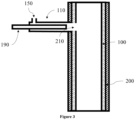
- Fig. 3 shows a section of an exemplary schematic graphitization furnace according to the first aspect comprising a cold trap.
- the cold trap may be for example a cooling rod 190.
- the cooling rod 190 may comprise or consist of graphite. Graphite may exhibit a high thermal resistance. Further, depending on the grade, graphite may exhibit a high thermal conductivity.
- the cold trap, e.g. the cooling rod 190 may be removed from the ash collection chamber 120 or ash outlet 110 to remove the ash from its surface. Removal of the ash form the surface may be performed for example by mechanical methods, e.g. milling the ash from the rod, or by chemical methods.
- the channel 100 is surrounded by the isolation structure 200 and the ash outlet 110 may be disposed within the isolation structure 200.
- the ash outlet 110 may not be directly connected to the channel 100, instead a gap 180 may be disposed between the isolation structure 200 and the channel 100.
- the gap 180 may also comprise additional components.
- a gas permeable material may be disposed between the channel 100 and the isolation structure 200, more specifically a particulate carbonaceous material and in particular pearled soot, particulate graphite, particulate coke; or carbon black. The pearled soot or carbon black may aid in thermally isolating the channel 100.
- the isolation structure 200 may comprise an isolation material. Additionally or alternatively, the isolation structure 200 may have a small interface with channel 100 and/or gas permeable material. Due to the small interface the rate of heat conduction from the channel 100 and/or gas permeable material to the isolation structure 200 may be low.
- the channel is gas permeable, more specifically the channel may comprise gas permeable graphite.
- the isolation structure may be gas impermeable, more specifically the isolation structure may comprise gas impermeable graphite.
- the reference to a gas permeable structure or material may in particular refer to a structure or material having a gas permeability of at least 0.3 cm 2 /s measured according to DIN 51935:2019-07.
- the reference to a gas-impermeable structure or material may in particular refer to a structure or material having a gas permeability of less than 0.3 cm 2 /s measured according to DIN 51935:2019-07.
- Suitable structures or materials having the required gas-(im)permeability are well-known to the skilled person. For instance, Sigrafine HLR, HLM and HLS grades may be used as gas permeable material, and Sigrafine HLX and isostatic graphite grades may be used as gas-impermeable material. All of these grades are available from SGL Carbon GmbH, Germany.
- the gas may therefore leave the channel 100 through the gas permeable graphite into the gap 180 and subsequently enter the ash outlet 110.
- the graphitization furnace comprises a second ash collection chamber in gaseous communication with the channel 100.
- the second ash collection chamber may comprise a second hatch and a second high surface area body removably disposed within the second ash collection chamber 120.
- the gas stream can be continuously removed from the graphitization furnace, for example, while the high surface area body 130 or high surface area body are exchanged or cleaned.
- the second ash collection chamber may comprise a second cooling means.
- the ash collection chamber 120 and the second ash collection chamber may be arranged such that they may be operated in parallel operation.
- the furnace may further contain one or more valve means to control the gaseous communication of the respective ash collection chamber 120 with the channel 100. As a result, the gas stream can be continuously removed from the graphitization furnace, for example, while the ash collection chamber 120 or second ash collection chamber are exchanged or cleaned.
- the present disclosure relates to a method of using a graphitization furnace according to any preceding embodiment for preparing graphite from a carbonaceous raw material.
- the method may yield graphite having a graphitization degree of at least about 46 %, more specifically 69 %, even more specifically at least about 80 % and in particular at least about 83 %.
- the crystallinity of a graphite may be described via its graphitization degree which may be measured by X-ray diffraction (XRD).
- XRD X-ray diffraction
- the crystalline carbon in the graphite forms a plurality of honeycomb lattices.
- the distance between the plurality of honeycomb lattices is described by the parameter "interplane distance d 002 .
- XRD may be used to measure the interplane distance d 001 between the plurality of lattices.
- An interplane distance d 002 of 0.3440 nm corresponds to the interplane distance of turbostratic graphite and an interplane distance of 0.3354 nm corresponds to the interplane distance in a perfect graphite crystal.
- a higher graphitization degree may correspond to a higher maximum discharge capacity.
- the method may yield graphite, which is suitable for use as anode material, in particular anode material for lithium batteries.
- the method further comprises the step of manufacturing an anode for lithium batteries using the graphite yielded from (continuously) operating the graphitization furnace.
Landscapes
- Engineering & Computer Science (AREA)
- Chemical & Material Sciences (AREA)
- Organic Chemistry (AREA)
- Mechanical Engineering (AREA)
- General Engineering & Computer Science (AREA)
- Inorganic Chemistry (AREA)
- Life Sciences & Earth Sciences (AREA)
- General Life Sciences & Earth Sciences (AREA)
- Geology (AREA)
- Carbon And Carbon Compounds (AREA)
Priority Applications (5)
| Application Number | Priority Date | Filing Date | Title |
|---|---|---|---|
| EP23170110.3A EP4455086A1 (de) | 2023-04-26 | 2023-04-26 | Graphitierungsofen mit einem ascheauslass |
| EP24723067.5A EP4701988A1 (de) | 2023-04-26 | 2024-04-26 | Graphitisierungsofen mit ascheauslass |
| PCT/EP2024/061665 WO2024223897A1 (en) | 2023-04-26 | 2024-04-26 | Graphitization furnace comprising an ash outlet |
| KR1020257039131A KR20260003065A (ko) | 2023-04-26 | 2024-04-26 | 회분 출구를 포함하는 흑연화로 |
| CN202480027035.6A CN121152768A (zh) | 2023-04-26 | 2024-04-26 | 包括灰分出口的石墨炉 |
Applications Claiming Priority (1)
| Application Number | Priority Date | Filing Date | Title |
|---|---|---|---|
| EP23170110.3A EP4455086A1 (de) | 2023-04-26 | 2023-04-26 | Graphitierungsofen mit einem ascheauslass |
Publications (1)
| Publication Number | Publication Date |
|---|---|
| EP4455086A1 true EP4455086A1 (de) | 2024-10-30 |
Family
ID=86226381
Family Applications (2)
| Application Number | Title | Priority Date | Filing Date |
|---|---|---|---|
| EP23170110.3A Withdrawn EP4455086A1 (de) | 2023-04-26 | 2023-04-26 | Graphitierungsofen mit einem ascheauslass |
| EP24723067.5A Pending EP4701988A1 (de) | 2023-04-26 | 2024-04-26 | Graphitisierungsofen mit ascheauslass |
Family Applications After (1)
| Application Number | Title | Priority Date | Filing Date |
|---|---|---|---|
| EP24723067.5A Pending EP4701988A1 (de) | 2023-04-26 | 2024-04-26 | Graphitisierungsofen mit ascheauslass |
Country Status (4)
| Country | Link |
|---|---|
| EP (2) | EP4455086A1 (de) |
| KR (1) | KR20260003065A (de) |
| CN (1) | CN121152768A (de) |
| WO (1) | WO2024223897A1 (de) |
Citations (3)
| Publication number | Priority date | Publication date | Assignee | Title |
|---|---|---|---|---|
| WO2015046200A1 (ja) * | 2013-09-25 | 2015-04-02 | 太平洋セメント株式会社 | セメントキルン抽気ガスの処理方法、塩素バイパスシステム及びセメント焼成装置 |
| CN113587643A (zh) * | 2021-07-01 | 2021-11-02 | 宁夏清波环保科技有限公司 | 一种立式真空电阻炉 |
| CN114105132A (zh) * | 2021-11-19 | 2022-03-01 | 四川金汇能新材料股份有限公司 | 连续石墨化系统 |
-
2023
- 2023-04-26 EP EP23170110.3A patent/EP4455086A1/de not_active Withdrawn
-
2024
- 2024-04-26 WO PCT/EP2024/061665 patent/WO2024223897A1/en not_active Ceased
- 2024-04-26 EP EP24723067.5A patent/EP4701988A1/de active Pending
- 2024-04-26 CN CN202480027035.6A patent/CN121152768A/zh active Pending
- 2024-04-26 KR KR1020257039131A patent/KR20260003065A/ko active Pending
Patent Citations (3)
| Publication number | Priority date | Publication date | Assignee | Title |
|---|---|---|---|---|
| WO2015046200A1 (ja) * | 2013-09-25 | 2015-04-02 | 太平洋セメント株式会社 | セメントキルン抽気ガスの処理方法、塩素バイパスシステム及びセメント焼成装置 |
| CN113587643A (zh) * | 2021-07-01 | 2021-11-02 | 宁夏清波环保科技有限公司 | 一种立式真空电阻炉 |
| CN114105132A (zh) * | 2021-11-19 | 2022-03-01 | 四川金汇能新材料股份有限公司 | 连续石墨化系统 |
Also Published As
| Publication number | Publication date |
|---|---|
| EP4701988A1 (de) | 2026-03-04 |
| KR20260003065A (ko) | 2026-01-06 |
| WO2024223897A1 (en) | 2024-10-31 |
| CN121152768A (zh) | 2025-12-16 |
Similar Documents
| Publication | Publication Date | Title |
|---|---|---|
| CN101688759B (zh) | 回转炉底式还原炉的排气处理装置以及方法 | |
| CN102159754B (zh) | 用于减少熔体污染和减少晶片污染的定向固化炉 | |
| JP2008545840A (ja) | 炭素質原料から特定の構成のガスへと変換するためのシステム | |
| BRPI0621931A2 (pt) | sistema de extração de óleo para a pirólise de materiais residuais de plástico e método de extração de óleo para a pirólise de materiais residuais de plástico | |
| CN110066987B (zh) | 气相沉积装置及氧化亚硅的制备方法 | |
| EP4455086A1 (de) | Graphitierungsofen mit einem ascheauslass | |
| JP5114759B2 (ja) | 石炭乾留ガス熱間処理設備及びコークス炉ガス熱間処理設備 | |
| JP2026513639A (ja) | 灰分出口部を含む黒鉛化炉 | |
| JP4680521B2 (ja) | SiO発生装置及びSiO製造装置 | |
| CN208952663U (zh) | 用于再生回收铜环保冶炼炉 | |
| CN105018731A (zh) | 铅阳极泥熔炼烟尘气化及分级控温回收工艺 | |
| US12458904B2 (en) | Method and apparatus to condense magnesium vapor using a fluid-cooled heat exchanger | |
| CN117512778A (zh) | 保温结构的异常监测方法 | |
| JPS6246184A (ja) | 長型炭素物品の連続的製造用焼成炉 | |
| CN210885323U (zh) | 连续高温提纯设备 | |
| JP5479756B2 (ja) | 熱処理炉およびこれを用いた排ガス処理装置 | |
| JP5068720B2 (ja) | 球状粒子製造装置 | |
| CN220642981U (zh) | 一种煤综合热解的分层布气炉型结构及装置 | |
| KR960003936B1 (ko) | 카본부착방지를 겸한 코크스로 발생가스의 현열회수방법 및 그 장치 | |
| CN216333097U (zh) | 高温粉料的出料降温系统 | |
| CN215799299U (zh) | 一种炭化炉热解气处理系统 | |
| KR20250162854A (ko) | 캐스케이딩 흑연화로 | |
| JP2025151496A (ja) | 堆積物の除去装置及び堆積物の除去方法 | |
| CN116839361A (zh) | 一种双推板窑窑内化合物快排的方法及双推板窑 | |
| CN117488402A (zh) | 蓝宝石晶体生长炉的温度调控方法 |
Legal Events
| Date | Code | Title | Description |
|---|---|---|---|
| PUAI | Public reference made under article 153(3) epc to a published international application that has entered the european phase |
Free format text: ORIGINAL CODE: 0009012 |
|
| STAA | Information on the status of an ep patent application or granted ep patent |
Free format text: STATUS: THE APPLICATION HAS BEEN PUBLISHED |
|
| AK | Designated contracting states |
Kind code of ref document: A1 Designated state(s): AL AT BE BG CH CY CZ DE DK EE ES FI FR GB GR HR HU IE IS IT LI LT LU LV MC ME MK MT NL NO PL PT RO RS SE SI SK SM TR |
|
| STAA | Information on the status of an ep patent application or granted ep patent |
Free format text: STATUS: THE APPLICATION IS DEEMED TO BE WITHDRAWN |
|
| 18D | Application deemed to be withdrawn |
Effective date: 20250501 |