EP4454454A1 - Landwirtschaftliche arbeitsmaschine - Google Patents
Landwirtschaftliche arbeitsmaschine Download PDFInfo
- Publication number
- EP4454454A1 EP4454454A1 EP24157259.3A EP24157259A EP4454454A1 EP 4454454 A1 EP4454454 A1 EP 4454454A1 EP 24157259 A EP24157259 A EP 24157259A EP 4454454 A1 EP4454454 A1 EP 4454454A1
- Authority
- EP
- European Patent Office
- Prior art keywords
- working machine
- side wall
- cover
- agricultural
- designed
- Prior art date
- Legal status (The legal status is an assumption and is not a legal conclusion. Google has not performed a legal analysis and makes no representation as to the accuracy of the status listed.)
- Granted
Links
Images


Classifications
-
- F—MECHANICAL ENGINEERING; LIGHTING; HEATING; WEAPONS; BLASTING
- F01—MACHINES OR ENGINES IN GENERAL; ENGINE PLANTS IN GENERAL; STEAM ENGINES
- F01N—GAS-FLOW SILENCERS OR EXHAUST APPARATUS FOR MACHINES OR ENGINES IN GENERAL; GAS-FLOW SILENCERS OR EXHAUST APPARATUS FOR INTERNAL-COMBUSTION ENGINES
- F01N3/00—Exhaust or silencing apparatus having means for purifying, rendering innocuous, or otherwise treating exhaust
- F01N3/08—Exhaust or silencing apparatus having means for purifying, rendering innocuous, or otherwise treating exhaust for rendering innocuous
- F01N3/10—Exhaust or silencing apparatus having means for purifying, rendering innocuous, or otherwise treating exhaust for rendering innocuous by thermal or catalytic conversion of noxious components of exhaust
- F01N3/18—Exhaust or silencing apparatus having means for purifying, rendering innocuous, or otherwise treating exhaust for rendering innocuous by thermal or catalytic conversion of noxious components of exhaust characterised by methods of operation; Control
- F01N3/20—Exhaust or silencing apparatus having means for purifying, rendering innocuous, or otherwise treating exhaust for rendering innocuous by thermal or catalytic conversion of noxious components of exhaust characterised by methods of operation; Control specially adapted for catalytic conversion
- F01N3/206—Adding periodically or continuously substances to exhaust gases for promoting purification, e.g. catalytic material in liquid form, NOx reducing agents
- F01N3/2066—Selective catalytic reduction [SCR]
-
- A—HUMAN NECESSITIES
- A01—AGRICULTURE; FORESTRY; ANIMAL HUSBANDRY; HUNTING; TRAPPING; FISHING
- A01D—HARVESTING; MOWING
- A01D41/00—Combines, i.e. harvesters or mowers combined with threshing devices
- A01D41/02—Self-propelled combines
-
- A—HUMAN NECESSITIES
- A01—AGRICULTURE; FORESTRY; ANIMAL HUSBANDRY; HUNTING; TRAPPING; FISHING
- A01D—HARVESTING; MOWING
- A01D43/00—Mowers combined with apparatus performing additional operations while mowing
- A01D43/08—Mowers combined with apparatus performing additional operations while mowing with means for cutting up the mown crop, e.g. forage harvesters
-
- A—HUMAN NECESSITIES
- A01—AGRICULTURE; FORESTRY; ANIMAL HUSBANDRY; HUNTING; TRAPPING; FISHING
- A01D—HARVESTING; MOWING
- A01D67/00—Undercarriages or frames specially adapted for harvesters or mowers; Mechanisms for adjusting the frame; Platforms
-
- F—MECHANICAL ENGINEERING; LIGHTING; HEATING; WEAPONS; BLASTING
- F01—MACHINES OR ENGINES IN GENERAL; ENGINE PLANTS IN GENERAL; STEAM ENGINES
- F01N—GAS-FLOW SILENCERS OR EXHAUST APPARATUS FOR MACHINES OR ENGINES IN GENERAL; GAS-FLOW SILENCERS OR EXHAUST APPARATUS FOR INTERNAL-COMBUSTION ENGINES
- F01N2610/00—Adding substances to exhaust gases
- F01N2610/02—Adding substances to exhaust gases the substance being ammonia or urea
-
- F—MECHANICAL ENGINEERING; LIGHTING; HEATING; WEAPONS; BLASTING
- F01—MACHINES OR ENGINES IN GENERAL; ENGINE PLANTS IN GENERAL; STEAM ENGINES
- F01N—GAS-FLOW SILENCERS OR EXHAUST APPARATUS FOR MACHINES OR ENGINES IN GENERAL; GAS-FLOW SILENCERS OR EXHAUST APPARATUS FOR INTERNAL-COMBUSTION ENGINES
- F01N2610/00—Adding substances to exhaust gases
- F01N2610/14—Arrangements for the supply of substances, e.g. conduits
- F01N2610/1406—Storage means for substances, e.g. tanks or reservoirs
-
- F—MECHANICAL ENGINEERING; LIGHTING; HEATING; WEAPONS; BLASTING
- F01—MACHINES OR ENGINES IN GENERAL; ENGINE PLANTS IN GENERAL; STEAM ENGINES
- F01N—GAS-FLOW SILENCERS OR EXHAUST APPARATUS FOR MACHINES OR ENGINES IN GENERAL; GAS-FLOW SILENCERS OR EXHAUST APPARATUS FOR INTERNAL-COMBUSTION ENGINES
- F01N2610/00—Adding substances to exhaust gases
- F01N2610/14—Arrangements for the supply of substances, e.g. conduits
- F01N2610/1433—Pumps
Definitions
- the invention relates to an agricultural working machine according to the preamble of claim 1.
- An agricultural machine designed as a forage harvester is from the EP 1 518 453 B2 known.
- the EP 1 518 453 B2 proposes a storage device for storing liquids or objects that can be integrated into the body of the agricultural machine in a space-saving manner.
- Such a storage device can be arranged on the underside of the forage harvester, for example, or integrated into existing structures, in particular body parts.
- the disadvantage is that there is hardly any space available in the existing structures to arrange a storage device due to the large number of required working elements, and arranging a storage device on the outside of the forage harvester leads to an overall increase in the size of the forage harvester structure. For example, a reduced ground clearance of the forage harvester is accompanied by arranging the storage device on the bottom of the forage harvester.
- an agricultural working machine in particular a forage harvester, comprising an axle body with at least one ground engagement means arranged on the axle body, further comprising a wheel housing which comprises a fender which partially surrounds the ground engagement means radially on the outside and a side wall, wherein a storage space with a functional assembly located therein is arranged on the side wall.
- the invention has many advantages.
- the use of the space available in the wheel housing makes it possible to provide additional storage space without increasing the overall structure of the work machine.
- a functional assembly arranged in the wheel housing is particularly easy to access for maintenance work when the ground engagement device is at a steering angle.
- the functional assembly can be designed as a urea pump.
- Arranging the urea pump in the wheel housing is particularly advantageous because by moving the urea pump from the existing installation space in the working machine into the wheel housing, the installation space freed up in the working machine can be used to enlarge a fuel tank.
- Such a solution is significantly more cost-effective than arranging the tank structure in the wheel housing.
- the fender can be designed as a urea tank, at least in sections. Due to the spatial proximity to the functional assembly, which is preferably designed as a urea pump, such an embodiment is particularly advantageous.
- a further advantageous development provides that the functional assembly is designed as a reservoir for storing a fluid.
- axle body is designed as the rear axle of the working machine, wherein the rear axle is a steering axle.
- the functional assembly is easily accessible for any maintenance work, in particular without tools.
- the storage space can be surrounded by a cover at least in sections.
- the storage space is limited by the cover.
- the cover serves to protect the functional assembly.
- the cover can be designed as a projection on the side wall.
- the cover can comprise a substantially convex section that extends axially in the vertical direction of the work machine and a section that tapers from an upper edge of the substantially convex section in the vertical direction towards the side wall.
- a mounting plate is arranged on the side wall, whereby the cover can be detachably attached, preferably by means of a screw connection, to the mounting plate.
- a mounting plate is particularly advantageous for the arrangement of the functional module.
- the removable arrangement of the cover on the mounting plate is particularly advantageous for maintenance work on the functional module.
- a main frame of the work machine has a particularly stable structure, so that an arrangement of the mounting plate on the main frame is particularly advantageous.
- the cover can preferably be arranged above the axle body, so that a downward pivoting movement of the axle body is not limited by the cover.
- the cover can be arranged outside an area that can be covered by the ground engagement means during a steering operation, so that a maximum adjustable steering angle is spatially limited only by the side wall.
- Fig. 1 shows a schematic and exemplary representation of an agricultural working machine 12 designed as a forage harvester 1.
- the body of the forage harvester 1 is shown cut open in its front part, below a driver's cab 2, in order to be able to show internal, crop-processing assemblies or working units of the forage harvester 1.
- One of these assemblies or working units is a so-called chopper drum assembly 3 with a chopper drum 5 rotating about a rotation axis 4 extending in the transverse direction of the vehicle.
- a conveyor device 6 for crop material is arranged in front of the chopping drum assembly 3.
- the conveyor device 6 comprises several pairs of rollers 7, 8, each of which delimits a gap and is driven in opposite directions to feed the crop material conveyed through the gap to the chopping drum 5.
- the conveyor device 5 in turn carries a harvesting attachment 9 which can be exchanged in accordance with the crop to be picked up.
- Crop material shredded in the chopper drum assembly 3 is fed to a post-accelerator 10, which gives the shredded crop the necessary speed to pass through a discharge spout 11 and be loaded into an accompanying vehicle, not shown.
- Front ground engagement means 15 are arranged on an axle body 14 designed as a front axle 13.
- the rear ground engagement means 15 are arranged on opposite sides of the forage harvester 1 on an axle body 14 designed as a rear axle 16.
- the ground engagement means 15 are designed as wheels.
- the rear axle 16 is designed as a steering axle of the working machine 12.
- a ground engagement means 15 arranged on the rear axle 16 is arranged in a wheel housing 17.
- the wheel housing 17 comprises a fender 18 which partially encloses the ground engagement means 15 on the radial outside and a side wall 19.
- the side wall 19 is located behind the ground engagement means 15.
- the side wall 19 extends essentially flat in the vertical direction.
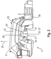
- FIG. 2 the wheel housing 17 is shown in more detail in a side view.
- a storage space 20 with a functional assembly 21 located in the storage space 20 is arranged on the side wall 19 of the wheel housing 17.
- the storage space 20 is surrounded by a cover 22.
- the cover forms a projection 31 that protrudes from the side wall 19 in the axial direction of the axle body 14.
- the projection 31 or the cover 22 is located above the axle body 14 designed as the rear axle 16.
- the cover 22 spatially delimits the storage space 20.
- the cover 22 consists of a substantially convex section 23.
- the substantially convex section 23 here and preferably consists of several flat sections. In the axial direction, the substantially convex section 23 extends in the vertical direction 25 of the forage harvester 1.
- the substantially convex section 23 is open at the top, with a section 26 tapering towards the side wall 19 being arranged on the upper edge 24 of the substantially convex section 23.
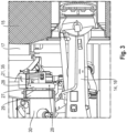
- Fig. 3 shows a cross section through the wheel housing 17.
- the cover 22 is in the view according to Fig. 3 hidden so that a functional assembly 21 arranged in the storage space 20 formed by the cover 22 can be seen.
- a mounting plate 27 can also be seen.
- the mounting plate 27 is arranged on the side wall 19 of the wheel housing 17.
- the mounting plate 27 is provided and designed to hold the functional assembly 21 and the cover 22.
- the cover 22 is detachably arranged on the mounting plate 27 by means of a screw connection.
- the mounting plate 27 comprises a plurality of recesses 28 for the screw connection.
- the side wall 19 is formed in sections by a main frame 29.
- the main frame 29 extends in the longitudinal direction of the work machine 12, with cross struts 30 for holding the front axle 13 and rear axle 16 being arranged on the main frame 29.
- Fig. 4 shows the ground engagement means 15 with the axle body 14 and the cover 22 in a top view. Furthermore, Fig. 4 two extreme positions 32 of the ground engagement means 15 are shown, which represent the maximum adjustable steering angle.
- the cover 22 is arranged outside of a surface 33 that can be reached or swept over during a steering process of the ground engagement means 15.
- the maximum adjustable steering angle is therefore spatially limited only by the side wall 19.
- the cover 22 forming the storage space 20 and the functional assembly 21 located in this storage space 20 are arranged in an area 34 located between the extreme positions 32 of the ground engagement means 15 and the side wall 19.
- the functional module 21 is designed as a Fig. 3 illustrated urea pump 35 is formed.
- An arrangement of the urea pump 35 in the area 34 is particularly advantageous because by moving the urea pump 35 from the installation space in the working machine 12 into the wheel housing 17, the installation space freed up in the working machine 12 can be used to enlarge a fuel tank. Such a solution is significantly more cost-effective than arranging the tank structure in the wheel housing.
- the functional assembly 21 can also be designed as a reservoir (not shown in detail here) for storing a fluid, such as fuel or urea.
- the functional assembly 21 is designed as a urea pump 35 and at the same time, as in Fig. 2 shown, a urea tank 36 is integrated into the fender 18.
Landscapes
- Life Sciences & Earth Sciences (AREA)
- Environmental Sciences (AREA)
- Chemical & Material Sciences (AREA)
- Engineering & Computer Science (AREA)
- Chemical Kinetics & Catalysis (AREA)
- Health & Medical Sciences (AREA)
- Toxicology (AREA)
- Combustion & Propulsion (AREA)
- Mechanical Engineering (AREA)
- General Engineering & Computer Science (AREA)
- Body Structure For Vehicles (AREA)
- Agricultural Machines (AREA)
Abstract
Description
- Die Erfindung betrifft eine landwirtschaftliche Arbeitsmaschine gemäß dem Oberbegriff des Anspruchs 1.
- Eine als Feldhäcksler ausgeführte landwirtschaftliche Arbeitsmaschine ist aus der
EP 1 518 453 B2 bekannt. DieEP 1 518 453 B2 schlägt eine sich in die Karosserie der landwirtschaftlichen Arbeitsmaschine bauraumsparend einfügende Speichervorrichtung zur Aufnahme von Flüssigkeiten oder Gegenständen vor. Eine derartige Speichervorrichtung kann beispielsweise untenseitig an dem Feldhäcksler angeordnet sein oder in bereits vorhandene Strukturen, insbesondere Karosserieteile, integriert werden. - Nachteilig ist, dass in den bereits vorhandenen Strukturen aufgrund einer Vielzahl erforderlicher Arbeitsorgane kaum Bauraum zur Anordnung einer Speichervorrichtung zur Verfügung steht und eine Anordnung einer Speichervorrichtung außenseitig an dem Feldhäcksler zu einer gesamtheitlichen Vergrößerung des Aufbaus des Feldhäckslers führt. Beispielsweise geht eine reduzierte Bodenfreiheit des Feldhäckslers mit einer Anordnung der Speichervorrichtung untenseitig an dem Feldhäcksler einher.
- Es ist deshalb Aufgabe der Erfindung, die beschriebenen Nachteile des Standes der Technik zu vermeiden und insbesondere den Stauraum für eine Funktionsbaugruppe an einer landwirtschaftlichen Arbeitsmaschine zu erweitern, ohne dass sich der gesamtheitliche Aufbau der Arbeitsmaschine vergrößert.
- Diese Aufgabe wird erfindungsgemäß durch die kennzeichnenden Merkmale des Anspruchs 1 gelöst.
- Gemäß dem Anspruch 1 wird eine landwirtschaftliche Arbeitsmaschine, insbesondere Feldhäcksler, vorgeschlagen, umfassend einen Achskörper mit zumindest einen an dem Achskörper angeordneten Bodeneingriffsmittel, weiterhin umfassend einen Radkasten der einen das Bodeneingriffsmittel radial außenseitig abschnittsweise umgebenden Kotflügel und eine Seitenwand umfasst, wobei an der Seitenwand ein Stauraum mit einer darin befindlichen Funktionsbaugruppe angeordnet ist.
- Die Erfindung hat viele Vorteile. Die Nutzung des in dem Radkasten vorhandenen Bauraums ermöglicht es ohne eine Vergrößerung der gesamtheitlichen Struktur der Arbeitsmaschine weiteren Stauraum bereitzustellen. Weiterhin ist eine in dem Radkasten angeordnete Funktionsbaugruppe bei einem eingeschlagenen Lenkwinkel des Bodeneingriffsmittels auf besonders einfache Art und Weise für Wartungsarbeiten zugänglich.
- Gemäß einer vorteilhaften Weiterbildung kann die Funktionsbaugruppe als eine Harnstoffpumpe ausgebildet sein. Eine Anordnung der Harnstoffpumpe in dem Radkasten ist besonders vorteilhaft, da durch die Verlagerung der Harnstoffpumpe aus dem in der Arbeitsmaschine vorhandenen Bauraum hinein in den Radkasten ein in der Arbeitsmaschine freiwerdender Bauraum für eine Vergrößerung eines Treibstofftanks nutzbar ist. Eine derartige Lösung ist wesentlich kostengünstiger, als eine Anordnung der Tankstruktur im Radkasten.
- Gemäß einer Ausgestaltung kann der Kotflügel zumindest abschnittsweise als Harnstofftank ausgebildet sein. Aufgrund der räumlichen Nähe zu der vorzugsweise als Harnstoffpumpe ausgebildeten Funktionsbaugruppe ist eine derartige Ausgestaltung besonders vorteilhaft.
- Eine weitere vorteilhafte Weiterbildung sieht vor, dass die Funktionsbaugruppe als ein Reservoir zum Speichern eines Fluids ausgebildet ist.
- Eine weitere vorteilhafte Ausgestaltung sieht vor, dass der Achskörper als Hinterachse der Arbeitsmaschine ausgebildet ist, wobei die Hinterachse eine Lenkachse ist. Hierbei ist bei einem eingelenkten Bodeneingriffsmittel die Funktionsbaugruppe für etwaige Wartungsarbeiten auf einfache Art und Weise, insbesondere werkzeuglos, zugänglich.
- Vorzugsweise kann der Stauraum zumindest abschnittsweise von einer Abdeckung umgeben sein. Der Stauraum ist hierbei durch die Abdeckung begrenzt. Zugleich dient die Abdeckung zum Schutz der Funktionsbaugruppe. Hierbei kann die Abdeckung als ein Vorsprung an der Seitenwand ausgebildet sein. Weiterhin kann die Abdeckung einen im Wesentlichen konvexen Abschnitt umfassen, der sich axial in Hochrichtung der Arbeitsmaschine erstreckt und einen sich ausgehend von einem oberen Rand des im Wesentlichen konvexen Abschnitts in Hochrichtung hin zu der Seitenwand verjüngenden Abschnitt umfassen.
- Besonders bevorzugt ist es, wenn an der Seitenwand eine Montageplatte angeordnet ist, wobei die Abdeckung lösbar, vorzugsweise mittels einer Schraubverbindung, an der Montageplatte angeordnet ist. Eine derartige Montageplatte ist besonders vorteilhaft zur Anordnung der Funktionsbaugruppe. Die Lösbare Anordnung der Abdeckung an der Montageplatte ist besonders vorteilhaft für Wartungsarbeiten an der Funktionsbaugruppe.
- Ein Hauptrahmen der Arbeitsmaschine weist einen besonders stabilen Aufbau auf, sodass eine Anordnung der Montageplatte an dem Hauptrahmen besonders vorteilhaft ist. Vorzugsweise kann die Abdeckung oberhalb des Achskörpers angeordnet sein, sodass eine nach unten gerichtete Schwenkbewegung des Achskörpers nicht durch die Abdeckung begrenzt ist.
- Vorzugsweise kann die Abdeckung außerhalb einer bei einem Lenkvorgang durch das Bodeneingriffsmittel überstreichbaren Fläche angeordnet sein, sodass ein maximal einstellbarer Lenkwinkel lediglich durch die Seitenwand räumlich begrenzt ist.
- Weitere vorteilhafte Ausgestaltungen sind Gegenstand weiterer Unteransprüche und werden nachfolgend an Hand eines in mehreren Figuren dargestellten Ausführungsbeispiels beschrieben. Es zeigen:
- Figur 1
- eine schematische Darstellung eines Feldhäckslers,
- Figur 2
- eine Seitenansicht eines Radkastens des Feldhäckslers,
- Figur 3
- einen Querschnitt durch den Radkasten des Feldhäckslers,
- Figur 4
- ein Bodeneingriffsmittel des Feldhäckslers in verschiedenen Stellungen in einer schematischen Draufsicht.
-
Fig. 1 zeigt eine schematische und exemplarische Darstellung einer als Feldhäcksler 1 ausgeführten landwirtschaftlichen Arbeitsmaschine 12. Die Karosserie des Feldhäckslers 1 ist in ihrem Vorderteil, unterhalb einer Fahrerkabine 2, aufgeschnitten dargestellt, um interne, Erntegut verarbeitende Baugruppen bzw. Arbeitsaggregate des Feldhäckslers 1 zeigen zu können. Eine dieser Baugruppen bzw. Arbeitsaggregate ist eine sogenannte Häckseltrommelbaugruppe 3 mit einer um eine sich in Fahrzeugquerrichtung erstreckende Rotationsachse 4 rotierende Häckseltrommel 5. - Der Häckseltrommelbaugruppe 3 ist eine Fördereinrichtung 6 für Erntegut vorgelagert. Die Fördereinrichtung 6 umfasst mehrere Walzenpaare 7, 8, die jeweils einen Spalt begrenzen und gegensinnig drehangetrieben sind, um das durch den Spalt hindurch geförderte Erntegut der Häckseltrommel 5 zuzuführen.
- Die Fördereinrichtung 5 trägt wiederum einen in Anpassung an das aufzunehmende Erntegut austauschbaren Erntevorsatz 9.
- In der Häckseltrommelbaugruppe 3 zerkleinertes Erntegut wird einem Nachbeschleuniger 10 zugeführt, der dem zerkleinerten Erntegut die nötige Geschwindigkeit verleiht, um einen Auswurfkrümmer 11 zu durchlaufen und in ein nicht dargestelltes Begleitfahrzeug übergeladen zu werden.
- An einem als Vorderachse 13 ausgebildeten Achskörper 14 sind vordere Bodeneingriffsmittel 15 angeordnet. An einem als Hinterachse 16 ausgebildeten Achskörper 14 sind an gegenüberliegenden Seiten des Feldhäckslers 1 die hinteren Bodeneingriffsmittel 15 angeordnet. Die Bodeneingriffsmittel 15 sind als Räder ausgebildet. Die Hinterachse 16 ist als Lenkachse der Arbeitsmaschine 12 ausgebildet.
- Ein an der Hinterachse 16 angeordnetes Bodeneingriffsmittel 15 ist in einem Radkasten 17 angeordnet. Der Radkasten 17 umfasst einen das Bodeneingriffsmittel 15 radial außenseitig abschnittsweise umschließenden Kotflügel 18 und eine Seitenwand 19. Die Seitenwand 19 befindet sich hinter dem Bodeneingriffsmittel 15. Die Seitenwand 19 erstreckt sich im Wesentlichen flächig in vertikaler Richtung.
- In
Fig. 2 ist der Radkasten 17 in einer Seitenansicht näher dargestellt. An der Seitenwand 19 des Radkastens 17 ist ein Stauraum 20 mit einer in dem Stauraum 20 befindlichen Funktionsbaugruppe 21 angeordnet. - Der Stauraum 20 ist von einer Abdeckung 22 umgeben. Die Abdeckung bildet einen in axialer Richtung des Achskörpers 14 von der Seitenwand 19 vorstehenden Vorsprung 31. Der Vorsprung 31 bzw. die Abdeckung 22 befindet sich oberhalb des als Hinterachse 16 ausgebildeten Achskörpers 14. Die Abdeckung 22 begrenzt räumlich den Stauraum 20.
- Hierbei besteht die Abdeckung 22 aus einem im Wesentlichen konvexen Abschnitt 23. Der im Wesentliche konvexe Abschnitt 23 besteht hier und vorzugsweise aus mehreren flächigen Abschnitten. In axialer Richtung erstreckt sich der im Wesentliche konvexe Abschnitt 23 in Hochrichtung 25 des Feldhäckslers 1. Der im Wesentlichen konvexe Abschnitt 23 ist nach oben offen ausgebildet, wobei sich an dem oberen Rand 24 des im Wesentlichen konvexen Abschnitts 23 ein sich hin zu der Seitenwand 19 verjüngender Abschnitt 26 angeordnet ist.
-
Fig. 3 zeigt einen Querschnitt durch den Radkasten 17. Die Abdeckung 22 ist in der Ansicht gemäßFig. 3 ausgeblendet, sodass eine in dem von der Abdeckung 22 gebildeten Stauraum 20 angeordnete Funktionsbaugruppe 21 ersichtlich ist. Weiterhin ist eine Montageplatte 27 ersichtlich. Die Montageplatte 27 ist an der Seitenwand 19 des Radkasten 17 angeordnet. Die Montageplatte 27 ist zur Halterung der Funktionsbaugruppe 21 und der Abdeckung 22 vorgesehen und eingerichtet. Die Abdeckung 22 ist lösbar mittels einer Schraubverbindung an der Montageplatte 27 angeordnet. Für die Schraubverbindung umfasst die Montageplatte 27 eine Mehrzahl von Aussparungen 28. - Hier und vorzugsweise ist die Seitenwand 19 abschnittsweise von einem Hauptrahmen 29 gebildet. Der Hauptrahmen 29 erstreckt sich in Längsrichtung der Arbeitsmaschine 12, wobei an dem Hauptrahmen 29 Querstreben 30 zur Halterung der Vorderachse 13 und Hinterachse 16 angeordnet sind.
-
Fig. 4 zeigt das Bodeneingriffsmittel 15 mit dem Achskörper 14 sowie der Abdeckung 22 in einer Draufsicht. Ferner sind inFig. 4 zwei Extremstellungen 32 des Bodeneingriffsmittels 15 abgebildet, welche den maximal einstellbaren Lenkeinschlag darstellen. - Die Abdeckung 22 ist außerhalb einer bei einem Lenkvorgang des Bodeneingriffsmittels 15 erreichbaren bzw. überstreichbaren Fläche 33 angeordnet. Mithin ist der maximal einstellbare Lenkwinkel lediglich durch die Seitenwand 19 räumlich begrenzt. Die den Stauraum 20 bildende Abdeckung 22 sowie die in diesem Stauraum 20 befindliche Funktionsbaugruppe 21 sind in einem zwischen den Extremstellungen 32 der Bodeneingriffsmittel 15 und der Seitenwand 19 befindliche Bereich 34 angeordnet.
- Die Funktionsbaugruppe 21 ist als eine in
Fig. 3 abgebildete Harnstoffpumpe 35 ausgebildet. Eine Anordnung der Harnstoffpumpe 35 in dem Bereich 34 ist besonders vorteilhaft, da durch die Verlagerung der Harnstoffpumpe 35 aus dem in der Arbeitsmaschine 12 vorhandenen Bauraum hinein in den Radkasten 17, der in der Arbeitsmaschine 12 freiwerdende Bauraum für eine Vergrößerung eines Treibstofftranks nutzbar ist. Eine derartige Lösung ist wesentlich kostengünstiger, als eine Anordnung der Tankstruktur im Radkasten. - Dennoch kann in einer alternativen Ausgestaltung die Funktionsbaugruppe 21 ebenfalls als ein hier nicht näher dargestelltes Reservoir zum Speichern eines Fluids, wie beispielsweise Kraftstoff oder Harnstoff, ausgebildet sein.
- Besonders vorteilhaft ist es jedoch, wenn auf Grund der räumlichen Nähe die Funktionsbaugruppe 21 als Harnstoffpumpe 35 ausgebildet ist und zugleich, wie in
Fig. 2 dargestellt, ein Harnstofftank 36 in den Kotflügel 18 integriert ist. -
1 Feldhäcksler 34 Bereich 2 Fahrerkabine 35 Harnstoffpumpe 3 Häckseltrommelbaugruppe 36 Harnstofftank 4 Rotationsachse 5 Häckseltrommel 6 Fördereinrichtung 7 Walzenpaar 8 Walzenpaar 9 Erntevorsatz 10 Nachbeschleuniger 11 Auswurfkrümmer 12 Arbeitsmaschine 13 Vorderachse 14 Achskörper 15 Bodeneingriffsmittel 16 Hinterachse 17 Radkasten 18 Kotflügel 19 Seitenwand 20 Stauraum 21 Funktionsbaugruppe 22 Abdeckung 23 Konvexer Abschnitt 24 Rand 25 Hochrichtung 26 Verjüngender Abschnitt 27 Montageplatte 28 Aussparung 29 Hauptrahmen 30 Querstreben 31 Vorsprung 32 Extremstellung 33 Fläche
Claims (12)
- Landwirtschaftliche Arbeitsmaschine (12), insbesondere Feldhäcksler (1), umfassend- einen Achskörper (14) mit zumindest einen an dem Achskörper (14) angeordneten Bodeneingriffsmittel (15),- einen Radkasten (17) der einen das Bodeneingriffsmittel (15) radial außenseitig abschnittsweise umgebenden Kotflügel (18) und eine Seitenwand (19) umfasstdadurch gekennzeichnet, dass
an der Seitenwand (19) ein Stauraum (20) mit einer darin befindlichen Funktionsbaugruppe (21) angeordnet ist. - Landwirtschaftliche Arbeitsmaschine (12) nach Anspruch 1, dadurch gekennzeichnet, dass die Funktionsbaugruppe (21) als eine Harnstoffpumpe (35) ausgebildet ist.
- Landwirtschaftliche Arbeitsmaschine (12) nach Anspruch 1, dadurch gekennzeichnet, dass die Funktionsbaugruppe (21) als ein Reservoir zum Speichern eines Fluids ausgebildet ist.
- Landwirtschaftliche Arbeitsmaschine (12) nach einem der Ansprüche 1 bis 3, dadurch gekennzeichnet, dass der Kotflügel (18) zumindest abschnittsweise als Harnstofftank (36) ausgebildet ist.
- Landwirtschaftliche Arbeitsmaschine (12) nach einem der Ansprüche 1 bis 4, dadurch gekennzeichnet, dass der Achskörper (14) als Hinterachse (16) der Arbeitsmaschine (12) ausgebildet ist, wobei die Hinterachse (16) eine Lenkachse ist.
- Landwirtschaftliche Arbeitsmaschine (12) nach einem der Ansprüche 1 bis 5, dadurch gekennzeichnet, dass der Stauraum (20) zumindest abschnittsweise von einer Abdeckung (22) umgeben ist.
- Landwirtschaftliche Arbeitsmaschine (12) nach Anspruch 6, dadurch gekennzeichnet, dass die Abdeckung (22) einen Vorsprung (31) an der Seitenwand (19) bildet.
- Landwirtschaftliche Arbeitsmaschine (12) nach einem der Ansprüche 6 bis 7, dadurch gekennzeichnet, dass die Abdeckung (22) einen im Wesentlichen konvexen Abschnitt (23), der sich axial in Hochrichtung (25) der Arbeitsmaschine (12) erstreckt und einen sich ausgehend von einem oberen Rand (24) des im Wesentlichen konvexen Abschnitts (23) in Hochrichtung (25) hin zu der Seitenwand (19) verjüngenden Abschnitt (26) umfasst.
- Landwirtschaftliche Arbeitsmaschine (12) nach einem der Ansprüche 6 bis 8, dadurch gekennzeichnet, dass an der Seitenwand (19) eine Montageplatte (27) angeordnet ist, wobei die Abdeckung (22) lösbar, vorzugsweise mittels einer Schraubverbindung, an der Montageplatte (27) angeordnet ist.
- Landwirtschaftliche Arbeitsmaschine (12) nach Anspruch 9, dadurch gekennzeichnet, dass die Montageplatte (27) an einem Hauptrahmen (29) der Arbeitsmaschine (12) angeordnet ist.
- Landwirtschaftliche Arbeitsmaschine (12) nach einem der Ansprüche 6 bis 10, dadurch gekennzeichnet, dass die Abdeckung (22) oberhalb des Achskörpers (14) angeordnet ist.
- Landwirtschaftliche Arbeitsmaschine (12) nach einem der Ansprüche 6 bis 11, dadurch gekennzeichnet, dass die Abdeckung (22) außerhalb einer bei einem Lenkvorgang durch das Bodeneingriffsmittel (15) überstreichbaren Fläche (33) angeordnet ist, sodass vorzugsweise ein maximal einstellbarer Lenkwinkel lediglich durch die Seitenwand (19) räumlich begrenzt ist.
Applications Claiming Priority (1)
| Application Number | Priority Date | Filing Date | Title |
|---|---|---|---|
| DE102023110350.4A DE102023110350A1 (de) | 2023-04-24 | 2023-04-24 | Landwirtschaftliche Arbeitsmaschine |
Publications (2)
| Publication Number | Publication Date |
|---|---|
| EP4454454A1 true EP4454454A1 (de) | 2024-10-30 |
| EP4454454B1 EP4454454B1 (de) | 2026-04-08 |
Family
ID=89940795
Family Applications (1)
| Application Number | Title | Priority Date | Filing Date |
|---|---|---|---|
| EP24157259.3A Active EP4454454B1 (de) | 2023-04-24 | 2024-02-13 | Landwirtschaftliche arbeitsmaschine |
Country Status (3)
| Country | Link |
|---|---|
| US (1) | US20240349646A1 (de) |
| EP (1) | EP4454454B1 (de) |
| DE (1) | DE102023110350A1 (de) |
Citations (6)
| Publication number | Priority date | Publication date | Assignee | Title |
|---|---|---|---|---|
| US3396983A (en) * | 1966-11-10 | 1968-08-13 | Lloyd H. Massey | Tractor apparatus |
| JPS63162329A (ja) * | 1986-12-26 | 1988-07-05 | Nissan Motor Co Ltd | キヤニスタの配置構造 |
| FR2707237A1 (fr) * | 1993-07-08 | 1995-01-13 | Coutier Moulage Gen Ind | Pare-boue pour véhicule automobile et son procédé de fabrication. |
| EP1518453B2 (de) | 2003-09-25 | 2013-04-10 | CLAAS Selbstfahrende Erntemaschinen GmbH | Speichervorrichtung innerhalb einer landwirtschaftlichen Erntemaschine |
| EP2949496A1 (de) * | 2014-05-28 | 2015-12-02 | Kubota Corporation | Véhicule de travail |
| US10821943B2 (en) * | 2018-05-24 | 2020-11-03 | Cnh Industrial America Llc | Storage tank assembly for a work vehicle |
-
2023
- 2023-04-24 DE DE102023110350.4A patent/DE102023110350A1/de active Pending
-
2024
- 2024-02-13 EP EP24157259.3A patent/EP4454454B1/de active Active
- 2024-04-24 US US18/644,257 patent/US20240349646A1/en active Pending
Patent Citations (6)
| Publication number | Priority date | Publication date | Assignee | Title |
|---|---|---|---|---|
| US3396983A (en) * | 1966-11-10 | 1968-08-13 | Lloyd H. Massey | Tractor apparatus |
| JPS63162329A (ja) * | 1986-12-26 | 1988-07-05 | Nissan Motor Co Ltd | キヤニスタの配置構造 |
| FR2707237A1 (fr) * | 1993-07-08 | 1995-01-13 | Coutier Moulage Gen Ind | Pare-boue pour véhicule automobile et son procédé de fabrication. |
| EP1518453B2 (de) | 2003-09-25 | 2013-04-10 | CLAAS Selbstfahrende Erntemaschinen GmbH | Speichervorrichtung innerhalb einer landwirtschaftlichen Erntemaschine |
| EP2949496A1 (de) * | 2014-05-28 | 2015-12-02 | Kubota Corporation | Véhicule de travail |
| US10821943B2 (en) * | 2018-05-24 | 2020-11-03 | Cnh Industrial America Llc | Storage tank assembly for a work vehicle |
Also Published As
| Publication number | Publication date |
|---|---|
| US20240349646A1 (en) | 2024-10-24 |
| DE102023110350A1 (de) | 2024-10-24 |
| EP4454454B1 (de) | 2026-04-08 |
Similar Documents
| Publication | Publication Date | Title |
|---|---|---|
| EP3391725B1 (de) | Schneckenfördererzusammenbau für einen mähdrescher | |
| EP3420803B1 (de) | Dresch- oder separierkorb für die getreideernte | |
| EP2979529B1 (de) | Zusammenklappbare landwirtschaftliche maschine | |
| DE4131491A1 (de) | Maiserntegeraet fuer feldhaecksler | |
| EP1709858A1 (de) | Erntevorsatz für landwirtschaftliche Erntemaschinen | |
| DE1952250U (de) | Prallschutzanordnung an landmaschinen, insbesondere schlegelfeldhaecksler. | |
| DE102021117214A1 (de) | Mähdrescher | |
| EP0503350A1 (de) | Arbeitsfahrzeug | |
| DE2007716A1 (de) | Verbesserung an auf landwirtschaftlichen Maschinen benutzten Rotor-Schneidwerken | |
| EP0832554A2 (de) | Mähdrescher | |
| DE2652162A1 (de) | Maehdrescher der axialflussbauart | |
| CH674294A5 (de) | ||
| EP4454454B1 (de) | Landwirtschaftliche arbeitsmaschine | |
| EP1894462B1 (de) | Landwirtschaftliches Trägerfahrzeug | |
| EP1709861B1 (de) | Auswurfkrümmer für einen Feldhäcksler | |
| DE3231953C2 (de) | ||
| EP0176057A2 (de) | Zerkleinerungsvorrichtung für organische Abfallmaterialien | |
| EP1894463B1 (de) | Landwirtschaftliche Erntemaschine mit einer Überladeeinrichtung | |
| EP4011190B1 (de) | Strohhäcksler | |
| DE102004015164B4 (de) | Wagen zur Abstützung eines Erntevorsatzes | |
| EP4136955A1 (de) | Schüttgutbehälter für eine erntemaschine | |
| EP4454922B1 (de) | Feldhäcksler | |
| EP2127516B1 (de) | Vorrichtung zum Entnehmen von Silagegut aus einem Silo | |
| EP4000378B1 (de) | Landwirtschaftliche arbeitsmaschine mit einer trommel | |
| AT392870B (de) | Feldhaecksler zum seitlichen anbau an ackerschlepper fuer die ernte von in reihen stehenden halmfruechten |
Legal Events
| Date | Code | Title | Description |
|---|---|---|---|
| PUAI | Public reference made under article 153(3) epc to a published international application that has entered the european phase |
Free format text: ORIGINAL CODE: 0009012 |
|
| STAA | Information on the status of an ep patent application or granted ep patent |
Free format text: STATUS: THE APPLICATION HAS BEEN PUBLISHED |
|
| AK | Designated contracting states |
Kind code of ref document: A1 Designated state(s): AL AT BE BG CH CY CZ DE DK EE ES FI FR GB GR HR HU IE IS IT LI LT LU LV MC ME MK MT NL NO PL PT RO RS SE SI SK SM TR |
|
| P01 | Opt-out of the competence of the unified patent court (upc) registered |
Free format text: CASE NUMBER: APP_63767/2024 Effective date: 20241202 |
|
| STAA | Information on the status of an ep patent application or granted ep patent |
Free format text: STATUS: REQUEST FOR EXAMINATION WAS MADE |
|
| 17P | Request for examination filed |
Effective date: 20250430 |
|
| GRAP | Despatch of communication of intention to grant a patent |
Free format text: ORIGINAL CODE: EPIDOSNIGR1 |
|
| STAA | Information on the status of an ep patent application or granted ep patent |
Free format text: STATUS: GRANT OF PATENT IS INTENDED |
|
| INTG | Intention to grant announced |
Effective date: 20251216 |
|
| GRAS | Grant fee paid |
Free format text: ORIGINAL CODE: EPIDOSNIGR3 |
|
| GRAA | (expected) grant |
Free format text: ORIGINAL CODE: 0009210 |
|
| STAA | Information on the status of an ep patent application or granted ep patent |
Free format text: STATUS: THE PATENT HAS BEEN GRANTED |
|
| AK | Designated contracting states |
Kind code of ref document: B1 Designated state(s): AL AT BE BG CH CY CZ DE DK EE ES FI FR GB GR HR HU IE IS IT LI LT LU LV MC ME MK MT NL NO PL PT RO RS SE SI SK SM TR |
|
| REG | Reference to a national code |
Ref country code: CH Ref legal event code: F10 Free format text: ST27 STATUS EVENT CODE: U-0-0-F10-F00 (AS PROVIDED BY THE NATIONAL OFFICE) Effective date: 20260408 Ref country code: GB Ref legal event code: FG4D Free format text: NOT ENGLISH |
|
| REG | Reference to a national code |
Ref country code: DE Ref legal event code: R096 Ref document number: 502024000986 Country of ref document: DE |