EP4453360B1 - Kraftwagentürscharnier mit türschliesshilfe - Google Patents
Kraftwagentürscharnier mit türschliesshilfe Download PDFInfo
- Publication number
- EP4453360B1 EP4453360B1 EP21848369.1A EP21848369A EP4453360B1 EP 4453360 B1 EP4453360 B1 EP 4453360B1 EP 21848369 A EP21848369 A EP 21848369A EP 4453360 B1 EP4453360 B1 EP 4453360B1
- Authority
- EP
- European Patent Office
- Prior art keywords
- hinge
- bracket
- door
- cam follower
- cam
- Prior art date
- Legal status (The legal status is an assumption and is not a legal conclusion. Google has not performed a legal analysis and makes no representation as to the accuracy of the status listed.)
- Active
Links
Images




Classifications
-
- E—FIXED CONSTRUCTIONS
- E05—LOCKS; KEYS; WINDOW OR DOOR FITTINGS; SAFES
- E05F—DEVICES FOR MOVING WINGS INTO OPEN OR CLOSED POSITION; CHECKS FOR WINGS; WING FITTINGS NOT OTHERWISE PROVIDED FOR, CONCERNED WITH THE FUNCTIONING OF THE WING
- E05F1/00—Closers or openers for wings, not otherwise provided for in this subclass
- E05F1/08—Closers or openers for wings, not otherwise provided for in this subclass spring-actuated, e.g. for horizontally sliding wings
- E05F1/10—Closers or openers for wings, not otherwise provided for in this subclass spring-actuated, e.g. for horizontally sliding wings for swinging wings, e.g. counterbalance
- E05F1/12—Mechanisms in the shape of hinges or pivots, operated by springs
- E05F1/1207—Mechanisms in the shape of hinges or pivots, operated by springs with a coil spring parallel with the pivot axis
- E05F1/1223—Mechanisms in the shape of hinges or pivots, operated by springs with a coil spring parallel with the pivot axis with a compression or traction spring
-
- E—FIXED CONSTRUCTIONS
- E05—LOCKS; KEYS; WINDOW OR DOOR FITTINGS; SAFES
- E05D—HINGES OR SUSPENSION DEVICES FOR DOORS, WINDOWS OR WINGS
- E05D11/00—Additional features or accessories of hinges
- E05D11/06—Devices for limiting the opening movement of hinges
-
- E—FIXED CONSTRUCTIONS
- E05—LOCKS; KEYS; WINDOW OR DOOR FITTINGS; SAFES
- E05D—HINGES OR SUSPENSION DEVICES FOR DOORS, WINDOWS OR WINGS
- E05D11/00—Additional features or accessories of hinges
- E05D11/08—Friction devices between relatively-movable hinge parts
- E05D11/087—Friction devices between relatively-movable hinge parts with substantially axial friction, e.g. friction disks
-
- E—FIXED CONSTRUCTIONS
- E05—LOCKS; KEYS; WINDOW OR DOOR FITTINGS; SAFES
- E05D—HINGES OR SUSPENSION DEVICES FOR DOORS, WINDOWS OR WINGS
- E05D11/00—Additional features or accessories of hinges
- E05D11/10—Devices for preventing movement between relatively-movable hinge parts
- E05D11/1028—Devices for preventing movement between relatively-movable hinge parts for maintaining the hinge in two or more positions, e.g. intermediate or fully open
- E05D11/1078—Devices for preventing movement between relatively-movable hinge parts for maintaining the hinge in two or more positions, e.g. intermediate or fully open the maintaining means acting parallel to the pivot
- E05D11/1085—Devices for preventing movement between relatively-movable hinge parts for maintaining the hinge in two or more positions, e.g. intermediate or fully open the maintaining means acting parallel to the pivot specially adapted for vehicles
-
- E—FIXED CONSTRUCTIONS
- E05—LOCKS; KEYS; WINDOW OR DOOR FITTINGS; SAFES
- E05D—HINGES OR SUSPENSION DEVICES FOR DOORS, WINDOWS OR WINGS
- E05D7/00—Hinges or pivots of special construction
- E05D7/12—Hinges or pivots of special construction to allow easy detachment of the hinge from the wing or the frame
- E05D7/121—Hinges or pivots of special construction to allow easy detachment of the hinge from the wing or the frame specially adapted for vehicles
-
- E—FIXED CONSTRUCTIONS
- E05—LOCKS; KEYS; WINDOW OR DOOR FITTINGS; SAFES
- E05D—HINGES OR SUSPENSION DEVICES FOR DOORS, WINDOWS OR WINGS
- E05D7/00—Hinges or pivots of special construction
- E05D7/10—Hinges or pivots of special construction to allow easy separation or connection of the parts at the hinge axis
- E05D7/1044—Hinges or pivots of special construction to allow easy separation or connection of the parts at the hinge axis in an axial direction
-
- E—FIXED CONSTRUCTIONS
- E05—LOCKS; KEYS; WINDOW OR DOOR FITTINGS; SAFES
- E05Y—INDEXING SCHEME ASSOCIATED WITH SUBCLASSES E05D AND E05F, RELATING TO CONSTRUCTION ELEMENTS, ELECTRIC CONTROL, POWER SUPPLY, POWER SIGNAL OR TRANSMISSION, USER INTERFACES, MOUNTING OR COUPLING, DETAILS, ACCESSORIES, AUXILIARY OPERATIONS NOT OTHERWISE PROVIDED FOR, APPLICATION THEREOF
- E05Y2201/00—Constructional elements; Accessories therefor
- E05Y2201/40—Motors; Magnets; Springs; Weights; Accessories therefor
- E05Y2201/47—Springs
- E05Y2201/474—Compression springs
-
- E—FIXED CONSTRUCTIONS
- E05—LOCKS; KEYS; WINDOW OR DOOR FITTINGS; SAFES
- E05Y—INDEXING SCHEME ASSOCIATED WITH SUBCLASSES E05D AND E05F, RELATING TO CONSTRUCTION ELEMENTS, ELECTRIC CONTROL, POWER SUPPLY, POWER SIGNAL OR TRANSMISSION, USER INTERFACES, MOUNTING OR COUPLING, DETAILS, ACCESSORIES, AUXILIARY OPERATIONS NOT OTHERWISE PROVIDED FOR, APPLICATION THEREOF
- E05Y2201/00—Constructional elements; Accessories therefor
- E05Y2201/40—Motors; Magnets; Springs; Weights; Accessories therefor
- E05Y2201/499—Spring tensioners; Tension sensors
-
- E—FIXED CONSTRUCTIONS
- E05—LOCKS; KEYS; WINDOW OR DOOR FITTINGS; SAFES
- E05Y—INDEXING SCHEME ASSOCIATED WITH SUBCLASSES E05D AND E05F, RELATING TO CONSTRUCTION ELEMENTS, ELECTRIC CONTROL, POWER SUPPLY, POWER SIGNAL OR TRANSMISSION, USER INTERFACES, MOUNTING OR COUPLING, DETAILS, ACCESSORIES, AUXILIARY OPERATIONS NOT OTHERWISE PROVIDED FOR, APPLICATION THEREOF
- E05Y2201/00—Constructional elements; Accessories therefor
- E05Y2201/60—Suspension or transmission members; Accessories therefor
- E05Y2201/622—Suspension or transmission members elements
- E05Y2201/628—Bearings
- E05Y2201/632—Sleeves
-
- E—FIXED CONSTRUCTIONS
- E05—LOCKS; KEYS; WINDOW OR DOOR FITTINGS; SAFES
- E05Y—INDEXING SCHEME ASSOCIATED WITH SUBCLASSES E05D AND E05F, RELATING TO CONSTRUCTION ELEMENTS, ELECTRIC CONTROL, POWER SUPPLY, POWER SIGNAL OR TRANSMISSION, USER INTERFACES, MOUNTING OR COUPLING, DETAILS, ACCESSORIES, AUXILIARY OPERATIONS NOT OTHERWISE PROVIDED FOR, APPLICATION THEREOF
- E05Y2201/00—Constructional elements; Accessories therefor
- E05Y2201/60—Suspension or transmission members; Accessories therefor
- E05Y2201/622—Suspension or transmission members elements
- E05Y2201/638—Cams; Ramps
-
- E—FIXED CONSTRUCTIONS
- E05—LOCKS; KEYS; WINDOW OR DOOR FITTINGS; SAFES
- E05Y—INDEXING SCHEME ASSOCIATED WITH SUBCLASSES E05D AND E05F, RELATING TO CONSTRUCTION ELEMENTS, ELECTRIC CONTROL, POWER SUPPLY, POWER SIGNAL OR TRANSMISSION, USER INTERFACES, MOUNTING OR COUPLING, DETAILS, ACCESSORIES, AUXILIARY OPERATIONS NOT OTHERWISE PROVIDED FOR, APPLICATION THEREOF
- E05Y2201/00—Constructional elements; Accessories therefor
- E05Y2201/60—Suspension or transmission members; Accessories therefor
- E05Y2201/622—Suspension or transmission members elements
- E05Y2201/696—Screw mechanisms
-
- E—FIXED CONSTRUCTIONS
- E05—LOCKS; KEYS; WINDOW OR DOOR FITTINGS; SAFES
- E05Y—INDEXING SCHEME ASSOCIATED WITH SUBCLASSES E05D AND E05F, RELATING TO CONSTRUCTION ELEMENTS, ELECTRIC CONTROL, POWER SUPPLY, POWER SIGNAL OR TRANSMISSION, USER INTERFACES, MOUNTING OR COUPLING, DETAILS, ACCESSORIES, AUXILIARY OPERATIONS NOT OTHERWISE PROVIDED FOR, APPLICATION THEREOF
- E05Y2600/00—Mounting or coupling arrangements for elements provided for in this subclass
- E05Y2600/10—Adjustable
-
- E—FIXED CONSTRUCTIONS
- E05—LOCKS; KEYS; WINDOW OR DOOR FITTINGS; SAFES
- E05Y—INDEXING SCHEME ASSOCIATED WITH SUBCLASSES E05D AND E05F, RELATING TO CONSTRUCTION ELEMENTS, ELECTRIC CONTROL, POWER SUPPLY, POWER SIGNAL OR TRANSMISSION, USER INTERFACES, MOUNTING OR COUPLING, DETAILS, ACCESSORIES, AUXILIARY OPERATIONS NOT OTHERWISE PROVIDED FOR, APPLICATION THEREOF
- E05Y2600/00—Mounting or coupling arrangements for elements provided for in this subclass
- E05Y2600/10—Adjustable
- E05Y2600/20—Adjustable with specific transmission movement
-
- E—FIXED CONSTRUCTIONS
- E05—LOCKS; KEYS; WINDOW OR DOOR FITTINGS; SAFES
- E05Y—INDEXING SCHEME ASSOCIATED WITH SUBCLASSES E05D AND E05F, RELATING TO CONSTRUCTION ELEMENTS, ELECTRIC CONTROL, POWER SUPPLY, POWER SIGNAL OR TRANSMISSION, USER INTERFACES, MOUNTING OR COUPLING, DETAILS, ACCESSORIES, AUXILIARY OPERATIONS NOT OTHERWISE PROVIDED FOR, APPLICATION THEREOF
- E05Y2600/00—Mounting or coupling arrangements for elements provided for in this subclass
- E05Y2600/50—Mounting methods; Positioning
- E05Y2600/51—Screwing or bolting
-
- E—FIXED CONSTRUCTIONS
- E05—LOCKS; KEYS; WINDOW OR DOOR FITTINGS; SAFES
- E05Y—INDEXING SCHEME ASSOCIATED WITH SUBCLASSES E05D AND E05F, RELATING TO CONSTRUCTION ELEMENTS, ELECTRIC CONTROL, POWER SUPPLY, POWER SIGNAL OR TRANSMISSION, USER INTERFACES, MOUNTING OR COUPLING, DETAILS, ACCESSORIES, AUXILIARY OPERATIONS NOT OTHERWISE PROVIDED FOR, APPLICATION THEREOF
- E05Y2600/00—Mounting or coupling arrangements for elements provided for in this subclass
- E05Y2600/60—Mounting or coupling members; Accessories therefor
- E05Y2600/61—Threaded members
-
- E—FIXED CONSTRUCTIONS
- E05—LOCKS; KEYS; WINDOW OR DOOR FITTINGS; SAFES
- E05Y—INDEXING SCHEME ASSOCIATED WITH SUBCLASSES E05D AND E05F, RELATING TO CONSTRUCTION ELEMENTS, ELECTRIC CONTROL, POWER SUPPLY, POWER SIGNAL OR TRANSMISSION, USER INTERFACES, MOUNTING OR COUPLING, DETAILS, ACCESSORIES, AUXILIARY OPERATIONS NOT OTHERWISE PROVIDED FOR, APPLICATION THEREOF
- E05Y2900/00—Application of doors, windows, wings or fittings thereof
- E05Y2900/50—Application of doors, windows, wings or fittings thereof for vehicles
- E05Y2900/53—Type of wing
- E05Y2900/531—Doors
Definitions
- This disclosure relates to hinges, and more particularly to automotive door hinges that facilitate closure of a vehicle door in relation to a vehicle body and separation of the vehicle door from the vehicle body.
- automotive door hinges include a vehicle door component and a vehicle body component rigidly mounted onto a vehicle door and a vehicle body, respectively.
- the door component is rotationally connected to the body component using a pivot pin rigidly mounted to either of the door component and the body component, the other of the door component and the body component being free to rotate about the pivot pin.
- door closure resistance may be caused by an interior cabin pressure, such as in cases where all windows are closed, or by a mass of the door, such as in cases where the vehicle is parked downwards on a hill, causing the door to swing open.
- Door closure resistance may also be experienced during compression of door seals and full engagement of a door latch mechanism to a striker.
- GB 1397776 to Guionic discloses a hinge having a door opening detent.
- the hinge has a greater torque requirement for door closure than for door opening which does not assist in overcoming door closure resistance.
- DE 202020101385U1 discloses a door hinge which also is not directed to overcoming door closure resistance.
- An aspect of the invention includes a hinge adapted to rotationally connect a vehicle door and a vehicle body, comprising: a first bracket mountable to one of the door and the body, the first bracket comprising a first housing; a second bracket mountable to the other of the door and the body; a cam element non-rotationally mounted to the second bracket comprising a cam surface adapted to engage a cam follower, the cam element having a first shaft housed in the first housing configured to rotationally couple the first bracket to the second bracket; the cam follower non-rotationally housed within the first housing and adapted to translate longitudinally within the first housing when engaged with the cam surface; and an energy storage means adapted to store energy when the cam follower longitudinally translates in a first direction and to release energy when the cam follower longitudinally translates in a second direction opposite to the first direction, wherein: relative rotation of the first bracket in relation to the second bracket within
- the cam surface comprises at least one cam element sloped surface and the cam follower comprises at least one cam follower sloped surface adapted to engage the at least one cam element sloped surface.
- the hinge is in a closed hinge state when the cam follower can no longer move rotationally in relation to the cam element and no further energy is releasable by the energy storage means; the hinge is in a first partially open hinge state when the at least one cam follower sloped surface is engaged with the cam element sloped surface and further energy may be stored or released by the energy storage means as the door is rotated; the hinge is in a second partially open hinge state when a first level surface of the cam follower abuts a second level surface of the cam element, permitting relative rotation therebetween without further storage or release of energy by the energy storage means; and the hinge is in a full open hinge state when the cam follower can no longer move rotationally in relation to the cam element and no further energy can be stored by the energy storage means.
- the first shaft is cylindrical; the energy storage means is adapted to encircle the first shaft; and the cam follower is adapted to encircle the first shaft so as to slidingly couple with the first shaft longitudinally and rotate in relation to the first shaft.
- the hinge further comprises holding means to engage the first shaft to restrict the cam element from translating longitudinally in the first housing.
- said holding means further causes the energy storage means to store an initial amount of energy to apply at least a predetermined amount of a preload to the cam follower.
- said holding means comprises a pin which is non-rotationally connected to the first shaft and rotates in a bushing when mounted in the first housing.
- the cam element further comprises a second shaft which projects oppositely to the first shaft; the second shaft is seated non-rotationally within a second housing of the second bracket; and a fastening means attached to the second shaft fixes the cam element to the second housing.
- the second shaft comprises a threaded portion; and the fastening means comprises a threaded fastener adapted to engage the correspondingly threaded portion of the second shaft whereby the first bracket is separable from the second bracket by removing the fastener and releasing the second shaft from within the second housing.
- the cam element comprises a first anti-rotation feature and the second bracket comprises a second anti-rotation feature adapted to engage the first anti-rotation feature to inhibit rotation between the cam element and the second bracket.
- the first anti-rotation feature comprises a male polygonal taper mating surface of a conical joint and the second anti-rotation feature comprises a female polygonal taper mating surface of the conical joint.
- the hinge further comprises at least one longitudinal groove depressed into one of an interior cylindrical surface of the first housing and a circumferential surface of the cam follower and at least one spline extending longitudinally from the other of the interior cylindrical surface of the first housing and the circumferential surface of the cam follower, wherein the at least one spline is adapted to engage with and translate longitudinally within the at least one groove so as to prevent rotation of the cam follower within the first housing while facilitating longitudinal translation of the cam follower within the first housing.
- the hinge operates in conjunction with a door checker configured to hold the door in multiple rotational positions in relation to the body.
- a second hinge connecting the door to the body comprises the door checker.
- the energy storage means comprises a spring.
- the spring comprises a coil spring.
- a friction between a first level surface of the cam follower and a second level surface of the cam element provides a door checking function.
- the hinge further comprises a releasable fastening means configured to retain the first bracket and the second bracket in an assembly.
- An aspect of the invention includes a hinge adapted to rotationally connect a vehicle door and a vehicle body.
- the hinge includes a first bracket and a second bracket, each mountable to either the door or the body using any of fixed fasteners, welding, bonding, riveting or other means.
- the first bracket may be mounted to the door and the second bracket may be mounted to the body.
- the first bracket may be mounted to the body and the second bracket may be mounted to the door.
- a cam follower is non-rotationally housed within a first housing of the first bracket and is adapted to translate longitudinally within the first housing.
- the cam follower may include a reciprocating plunger.
- a cam element is non-rotationally mounted to the second bracket and includes a cam surface adapted to engage the cam follower.
- An energy storage means is adapted to store energy when the cam follower longitudinally translates in a first direction and to release energy when the cam follower longitudinally translates in a second direction opposite to the first direction.
- the energy storage means may include an elastic element such as a spring.
- the spring may be a constant rate spring or may be a variable rate spring.
- the energy storage means is a coil spring.
- Other possible energy storage means include compressible, elastic rubber or plastic components, compressed gas (e.g., gas cylinders) and thermal energy storage, though other energy storage means may be used as well.
- Rotation of the first bracket in relation to the second bracket within a predetermined angular range causes longitudinal translation of the cam follower.
- rotation of the first bracket causes the cam follower to rotate and engage with the cam surface.
- the cam follower engages with the cam surface, the cam follower longitudinally translates in the first direction within the first housing, causing the energy storage means to store energy.
- the first bracket rotates by a predetermined amount in relation to the second bracket (e.g., 4 degrees, 5 degrees, 7 degrees, or another amount) before the cam follower engages with the cam surface.
- the rotational clearance allows the door to be partially opened without any reacting cam forces between the cam follower and the cam surface of the cam element.
- This rotational clearance may be useful during door removal wherein the first bracket and the second bracket are separated.
- the rotational clearance may also account for overslam.
- Rotation of the first bracket past a predetermined position in relation to the second bracket e.g., 20 degrees, 30 degrees, 35 degrees, or another amount
- a predetermined position in relation to the second bracket e.g. 20 degrees, 30 degrees, 35 degrees, or another amount
- friction between the first level surface of the cam follower and second level surface of the cam element provides a door check function which helps keep the door open.
- the door close assist energy may be useful in situations requiring added effort to close the door.
- the door close assist energy may be helpful in overcoming door closure resistance arising from interior cabin pressure (e.g., in cases where all windows are closed) or mass of the door (e.g., in cases where the vehicle is parked downwards on a hill, causing the door to swing open).
- the door close assist energy may also be helpful in overcoming door closure resistance during compression of the door seals and during full engagement of the door latch mechanism to the striker.
- 3.5J of door close assist energy may be generated when the door has 30 degrees open angle in relation to the body.
- the cam element includes at least one cam element sloped surface (e.g., one, two, four, or another number of cam element sloped surfaces).
- the cam follower includes at least one cam follower sloped surface (e.g., one, two, four, or another number of cam follower sloped surfaces) adapted to engage the at least one cam element sloped surface.
- the number of cam follower sloped surfaces typically matches the number of cam element sloped surfaces.
- the hinge is in a partially open hinge state when the at least one cam follower sloped surface is engaged with the cam element sloped surface and further energy may be stored or released by the energy storage means as the door is rotated.
- the hinge may continue in a partially open hinge state when the first level surface of the cam follower abuts the second level surface of the cam element, permitting relative rotation therebetween without further storage or release of energy by the energy storage means.
- maximum energy is stored in the energy storage means in this phase of the partially open hinge state.
- the hinge is in a full open hinge state when the cam follower can no longer move rotationally in relation to the cam element and no further energy can be stored by the energy storage means.
- the hinge is in the full open hinge state when the first bracket rotates a predetermined amount or more (e.g., 25 degrees or more or 30 degrees or more) in relation to the second bracket.
- a predetermined amount or more e.g. 25 degrees or more or 30 degrees or more
- the at least one cam follower sloped surface is adapted to engage with the at least one cam element sloped surface after rotating the door open by a predetermined amount (e.g., 3 degrees, 5 degrees, 6 degrees, or another amount).
- the cam element includes a first shaft housed within the first housing.
- the first shaft is preferably cylindrical to facilitate rotation of the cam follower around the first shaft.
- the cam surface is advantageously positioned at an end of the first shaft and separated from the energy storage means by the cam follower.
- the energy storage means is adapted to encircle the first shaft.
- a spring, and in particular, a coil spring is an example of such an energy storage means.
- the cam follower is adapted to encircle the first shaft so as to slidingly couple with the first shaft longitudinally and rotate in relation to the first shaft.
- the first shaft is preferably cylindrical and the cam follower has a corresponding hollow cylindrical core.
- a holding means is used to engage the first shaft to restrict the cam element from translating longitudinally in the first housing.
- the holding means may cause the energy storage means to store an initial amount of energy to apply a preload to the cam follower.
- the holding means includes a bushing mounted in the first housing and a pin adapted to fit into and rotate relative to the bushing.
- the pin is press fitted into or onto the first shaft, causing the energy storage means to store an initial amount of energy and pre-load the cam follower.
- Other holding means may alternatively be used, such as a clip or a nut.
- the cam element includes a second shaft adapted to non-rotationally sit within a second housing of the second bracket, wherein a fastening means connected to the second shaft fixes the cam element to the second housing.
- the second shaft is threaded at a second shaft end adjacent an exterior end of the second housing distal from the first bracket. The second shaft end is accordingly also distal from the first shaft.
- the fastening means may comprise a threaded fastener adapted to engage the correspondingly threaded second shaft end.
- the first bracket is separable from the second bracket by removing the fastener and releasing the second shaft from within the second housing.
- cam element may include a disc-shaped feature adapted to sit between the first housing and the second housing.
- a bushing is positioned between the disc-shaped feature and the first housing.
- the cylindrical inner surface or bore of the first housing may include at least one longitudinal groove and the cam follower may include at least one spline extending longitudinally from a circumferential surface of the cam follower.
- the at least one spline is adapted to engage with and translate longitudinally within the at least one longitudinal groove to prevent rotation of the cam follower in relation to the first housing while facilitating longitudinal translation of the cam follower within the first housing.
- the same effect is achieved when the circumferential surface of the cam follower includes the at least one longitudinal groove and the cylindrical inner surface or bore of the first housing includes the at least one spline.
- the cam element includes a first anti-rotation feature and the second bracket includes a second anti-rotation feature.
- the second anti-rotation feature is adapted to engage the first anti-rotation feature to inhibit and preferably prevent rotation between the cam element and the second bracket.
- the first anti-rotation feature includes a male polygonal taper mating surface of a conical joint and the second anti-rotation feature includes a female polygonal taper mating surface of the conical joint.
- the first anti-rotation feature comprises one of a female square taper mating surface and a male square taper mating surface and the second anti-rotation feature comprises the other of the female square taper mating surface and the male square taper mating surface.
- first anti-rotation feature includes a projection and the second anti-rotation feature includes an indentation adapted to receive the projection and prevent rotation between the cam element and the second bracket.
- first anti-rotation feature and the second anti-rotation feature may also be useful in aligning the door bracket with the body bracket during assembly of the door to the body.
- the hinge operates in conjunction with a door checker to hold the door in multiple rotational positions.
- a second hinge connecting the door to the body may include the door checker.
- An example of such a door checker is described in U.S. Patent No. 6,481,056 .
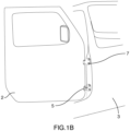
- FIGS. 1A and 1B illustrate an embodiment of a hinge (1) adapted to rotationally connect a vehicle door (2) and a vehicle body (3).
- the hinge includes a door bracket (4) and a body bracket (5).
- the door bracket (4) is mountable to the vehicle door (2) and includes a door housing (6) (see FIG. 2 ).
- the door bracket is fixed to the vehicle door (2) using fixed fasteners (7).
- the body bracket (5) is mountable to the vehicle body (3) and includes a body housing (8) (see FIG. 2 ).
- the body bracket (5) is fixed to the vehicle body (3) using fixed fasteners (7).
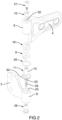
- FIG. 2 illustrates an exploded view of components of the hinge (1).
- FIGS. 3A-D 4A , and 4B illustrate an assembly of the components of the hinge (1).
- a cam follower (9) is non-rotationally housed within the door housing (6).
- the cam follower encircles a first shaft (10) of a cam element (11) non-rotationally mounted to the body bracket (5).
- the cam follower (9) is adapted to translate longitudinally within the door housing (6) along the first shaft (10), similar in manner to a reciprocating plunger.
- the cam follower (9) includes one or more splines (12) adapted to fit within longitudinal grooves (13) of the door housing (6) to prevent the cam follower (9) from rotating in relation to the door housing (6) and allow longitudinal translation of the cam follower (9) within the door housing (6) along the first shaft (10).
- the cam follower (9) further includes projections (14) adapted to fit within grooves (15) of the cam element (11).
- the projections (14) include cam follower sloped surfaces (16) adapted to engage with cam element sloped surfaces (17) of grooves (15).
- a spring (18) is housed within the door housing (6) and encircles the first shaft (10).
- the cam follower sloped surfaces (16) engage with and translate upwards along the cam element sloped surfaces (17), causing the cam follower (9) to longitudinally translate in a first direction, thereby compressing the spring (18) to store elastic energy.
- the cam follower sloped surfaces (16) engage with and translate downwards along the cam element sloped surfaces (17), causing the cam follower (9) to longitudinally translate in a second direction opposite to the first direction, thereby decompressing the spring (18) to release the elastic energy.
- a bushing (19) is press fit into a hole (20) in a top surface of the door housing (6).
- This may be a non-friction split bushing or another appropriate form of bushing.
- a pin (21) fits into the bushing (19) and is press fitted into the first shaft (10) positioned within the door housing (6).
- the pin (21) may be fitted onto the first shaft (10) or threaded into or onto the first shaft (10). The result is that the door housing (6) rotates in relation to the pin (21) and the first shaft (10) as the door (2) is opened and closed.
- the pin (21) causes the spring (18) to compress and pre-loads the cam follower (9).
- the cam element (11) further includes a conical feature (22) adapted to mate with a conical socket (23) depressed within the body housing (8).
- Mating surfaces of the conical feature (22) and the conical socket (23) include a male square taper mating surface (24) and a female square taper mating surface (25), respectively.
- square taper mating surfaces are preferred, other polygonal mating surfaces (e.g., triangular, pentagonal, etc.) may be employed.
- the cam element (11) further includes a second shaft (26) adapted to sit within a vertical passage (27) of the body housing (8).
- the second shaft (26) is threaded in order to engage with a fastener (28).
- the threading may extend over the length of the second shaft, or only over part of the length of the second shaft as required.
- the fastener (28) is fastened onto the threaded end of the second shaft (26) to fix the cam element (11) to the body bracket (5) and rotationally connect the door (2) and body (3).
- the fastener (28) is internally threaded while the second shaft (26) is externally threaded. Alternatively, the fastener (28) may be externally threaded while the second shaft (26) may be internally threaded.
- cam element (11) may be integral and/or some portions of the cam element (11) may be structurally fixed.
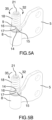
- FIGS. 5A-5C illustrate a function of the hinge (1).
- the door bracket (4) is intentionally omitted from FIGS. 5A-5C so as to not obstruct the components housed within the door housing (6).
- FIG. 5A illustrates the hinge (1) in a closed hinge state wherein the projections (14) are fully seated within the respective grooves (15), the cam follower (9) can no longer move in relation to the cam element (11), no further energy is releasable by the spring (18), and the door (2) is closed.
- the projections (14) are adapted to fit within the grooves (15) with a predetermined rotational clearance between the cam follower sloped surfaces (16) and the cam element sloped surfaces (17).
- FIG. 5B illustrates the hinge (1) in a first partially open hinge state wherein the door (2) is partially open, the cam follower sloped surfaces (16) engage the cam element sloped surfaces (17), and further energy may be stored or released by the spring (18) as the door is rotated.
- Rotation of the door bracket (4) in a first rotational direction (32) beyond the rotational clearance causes the cam follower (9), non-rotationally housed within the door housing (6), to rotate in the first rotational direction (32) by a same amount as the door bracket (4).
- the cam follower sloped surfaces (16) engage with the cam element sloped surfaces (17), causing the cam follower (9) to longitudinally translate upwards into the first housing (6) and compress the spring (18).
- FIG. 5C illustrates the hinge (1) in a second partially open hinge state wherein the door (2) is partially open, the projections (14) reach a level surface (33) of the cam element (11), the cam follower (9) can no longer move longitudinally in relation to the cam element (11), and essentially maximum energy is stored by the spring (18). Friction between a level surface (34) of the projections (14) and the level surface (33) of the cam element (11) provides a door check function.
- the hinge (1) is in the second partially open hinge state when the door bracket (4) rotates beyond a predetermined position in relation to the body bracket (5).
- the hinge (1) is in a fully open hinge state when the cam follower (9) can no longer move rotationally in relation to the cam element (11), and essentially maximum energy is still stored by the spring (18).
- the energy stored by the spring (18) in the fully open hinge state need not be the maximum energy stored during opening of the door (2) if a different energy storage profile is desired.
- the stored energy should be sufficient upon reaching the predetermined position during door closing to urge the door (2) closed, as further explained below.
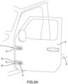
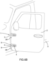
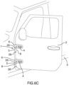
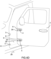
- FIGS. 6A-6D illustrate an embodiment of a process for separating the door (2) from the body (3).
- the door (2) is unlatched and opened.
- the fasteners (28) threaded onto the threaded ends of second shafts (26) are removed.
- FIG. 6C the door (2) is lifted upwards until the second shafts (26) are released from within the body brackets (5).
- the door (2) is set aside for stowage.
- the door (2) is rotationally reconnected to the body (3) by lifting the door (2) and lowering the second shafts (26) into the body housings (8) of the body brackets (5) until the surfaces (24) of the conical features (22) contact the surfaces (25) of the conical sockets (23). Then, to rotationally reconnect the door (2) to the body (3), the fasteners (28) are fastened to the threaded ends of the second shafts (26).
- the elements described herein may be modified as will be apparent to those skilled in the art.
- the elements may be rearranged such that the cam element is non-rotationally housed within the door housing and rotates with the door housing as the door opens and closes.
- the door housing and cam element rotate in relation to the cam follower.
- the cam element may be integral with or structurally fixed to the door housing or the body housing.
- the cam element includes two grooves and the cam follower includes two projections, a different number of grooves and projections may be used. Further, the position of the grooves relative to one another and the position of the projections of the cam follower relative to one another may differ from what is illustrated.
- longitudinal grooves and splines in or on the first housing and cam follower may be used than illustrated herein.
- the position of the longitudinal grooves relative to one another and the position of the splines relative to one another may differ from what is illustrated.
- the various components of the hinge may be manufactured using various manufacturing methods, such as stamping, forging, and casting.
- the various components of the hinge may be fabricated from various types of materials, such as metal and plastic.
- a lubricant or a material with impregnated lubricant may be used.
- a lubricant may be used for a metal cam follower.
Landscapes
- Engineering & Computer Science (AREA)
- Mechanical Engineering (AREA)
- Closing And Opening Devices For Wings, And Checks For Wings (AREA)
- Lock And Its Accessories (AREA)
- Hinge Accessories (AREA)
Claims (15)
- Scharnier (1), das angepasst ist, um eine Fahrzeugtür (2) und eine Fahrzeugkarosserie (3) in drehender Weise zu verbinden, umfassend:eine erste Halterung (4), die an einer von der Tür (2) und der Karosserie (3) montierbar ist, wobei die erste Halterung (4) ein erstes Gehäuse (6) umfasst;eine zweite Halterung (5), die an der anderen von der Tür (2) und der Karosserie (3) montierbar ist;ein Nockenelement (11), das in nicht drehender Weise an der zweiten Halterung (5) montiert ist und eine Nockenfläche (17) umfasst, die angepasst ist, um mit einem Nockenstößel (9) in Eingriff zu kommen, wobei das Nockenelement (11) eine erste Achse (10) aufweist, die im ersten Gehäuse (6) untergebracht und dafür konfiguriert ist, die erste Halterung (4) mit der zweiten Halterung (5) in drehender Weise zu koppeln;wobei der Nockenstößel (9) in nicht drehender Weise innerhalb des ersten Gehäuses (6) untergebracht und angepasst ist, um sich innerhalb des ersten Gehäuses (6) in Längsrichtung zu verschieben, wenn er mit der Nockenfläche (17) in Eingriff ist; undein Energiespeichermittel (18), das angepasst ist, um Energie zu speichern, wenn sich der Nockenstößel (9) in Längsrichtung in eine erste Richtung (32) verschiebt, und Energie freizusetzen, wenn sich der Nockenstößel (9) in Längsrichtung in eine zweite Richtung (35) entgegengesetzt zur ersten Richtung (32) verschiebt, wobei:eine relative Drehung der ersten Halterung (4) in Bezug auf die zweite Halterung (5) innerhalb eines vorbestimmten Winkelbereichs zwischen der ersten Halterung (4) und der zweiten Halterung (5) eine Längsverschiebung des Nockenstößels (9) bewirkt;eine Drehung der ersten Halterung (4) in einer ersten Drehrichtung (32) über eine vorbestimmte Position jenseits des vorbestimmten Winkelbereichs in Bezug auf die zweite Halterung (5) hinaus, wenn die Tür (2) geöffnet wird, dazu führt, dass eine erste ebene Fläche (34) des Nockenstößels (9) und eine zweite ebene Fläche (33) des Nockenelements (11) aneinander anliegen, wodurch die Längsverschiebung des Nockenstößels (9) in der ersten Richtung (32) aufhört; undeine Drehung der ersten Halterung (4) in einer zweiten Drehrichtung (35), die der ersten Drehrichtung (32) entgegengesetzt ist, über die vorbestimmte Position in Bezug auf die zweite Halterung (5) hinaus, wenn die Tür (2) geschlossen wird, dazu führt, dass der Nockenstößel (9) mit der Nockenfläche (17) in Eingriff kommt und sich in Längsrichtung in die zweite Richtung (35) verschiebt, wodurch die durch das Energiespeichermittel (18) gespeicherte Energie freigesetzt wird, um das Schließen der Tür (2) zu unterstützen.
- Scharnier (1) nach Anspruch 1, wobei:die Nockenfläche (17) mindestens eine abgeschrägte Nockenelementfläche (17) umfasst; undder Nockenstößel (9) mindestens eine abgeschrägte Nockenstößelfläche (16) umfasst, die angepasst ist, um mit der mindestens einen abgeschrägten Nockenelementfläche (17) in Eingriff zu kommen.
- Scharnier (1) nach Anspruch 2, wobei:das Scharnier (1) in einem geschlossenen Scharnierzustand ist, wenn sich der Nockenstößel (9) in Bezug auf das Nockenelement (11) nicht mehr in drehender Weise bewegen kann und keine weitere Energie durch das Energiespeichermittel (18) freisetzbar ist;das Scharnier (1) in einem ersten teilweise offenen Scharnierzustand ist, wenn die mindestens eine abgeschrägte Nockenstößelfläche (16) mit der abgeschrägten Nockenelementfläche (17) in Eingriff ist und weitere Energie durch das Energiespeichermittel (18) gespeichert oder freigesetzt werden kann, während die Tür (2) gedreht wird;das Scharnier (1) in einem zweiten teilweise offenen Scharnierzustand ist, wenn eine erste ebene Fläche des Nockenstößels (34) an einer zweiten ebenen Fläche des Nockenelements (33) anliegt, wodurch eine relative Drehung dazwischen ohne weitere Speicherung oder Freisetzung von Energie durch das Energiespeichermittel (18) ermöglicht wird; unddas Scharnier (1) in einem vollständig offenen Scharnierzustand ist, wenn sich der Nockenstößel (9) in Bezug auf das Nockenelement (11) nicht mehr in drehender Weise bewegen kann und keine weitere Energie durch das Energiespeichermittel (18) gespeichert werden kann.
- Scharnier (1) nach Anspruch 1, wobei:die erste Achse (10) zylindrisch ist;das Energiespeichermittel (18) angepasst ist, um die erste Achse (10) zu umschließen; undder Nockenstößel (9) angepasst ist, um die erste Achse (10) zu umschließen, sodass er mit der ersten Achse (10) in Längsrichtung gleitend gekoppelt wird und sich in Bezug auf die erste Achse (10) dreht.
- Scharnier (1) nach Anspruch 4, ferner umfassend:
ein Haltemittel (21), um mit der ersten Achse (10) in Eingriff zu kommen, um zu verhindern, dass das Nockenelement (11) sich im ersten Gehäuse (6) in Längsrichtung verschiebt. - Scharnier (1) nach Anspruch 5, wobei das Haltemittel (21) ferner bewirkt, dass das Energiespeichermittel (18) einen Anfangsenergiebetrag speichert, um mindestens einen vorbestimmten Betrag einer Vorspannkraft auf den Nockenstößel (9) auszuüben, oder wobei das Haltemittel (21) einen Stift (21) umfasst, der in nicht drehender Weise mit der ersten Achse (10) verbunden ist und sich in einer Buchse (19) dreht, wenn er im ersten Gehäuse (6) montiert ist.
- Scharnier (1) nach Anspruch 1, wobei:das Nockenelement (11) ferner eine zweite Achse (26) umfasst, die entgegengesetzt zu einer ersten Achse (10) vorspringt;die zweite Achse (26) in nicht drehender Weise innerhalb eines zweiten Gehäuses (8) der zweiten Halterung (5) gelagert ist; undein Befestigungsmittel (28), das an der zweiten Achse (26) angebracht ist, das Nockenelement (11) am zweiten Gehäuse (8) fixiert, wobei optional:die zweite Achse (26) einen Abschnitt mit Gewinde umfasst; unddas Befestigungsmittel (28) ein Befestigungselement mit Gewinde umfasst, das angepasst ist, um mit dem entsprechenden Abschnitt mit Gewinde der zweiten Achse (26) in Eingriff zu kommen, wodurch die erste Halterung (4) durch Entfernen des Befestigungselements und Lösen der zweiten Achse (26) aus dem Inneren des zweiten Gehäuses (8) von der zweiten Halterung (5) trennbar ist.
- Scharnier (1) nach Anspruch 1, wobei:das Nockenelement (11) ein erstes Antirotationsmerkmal (22) umfasst; unddie zweite Halterung (5) ein zweites Antirotationsmerkmal (23) umfasst, das angepasst ist, um mit dem ersten Antirotationsmerkmal (22) in Eingriff zu kommen, um eine Drehung zwischen dem Nockenelement (11) und der zweiten Halterung (5) zu hindern, wobei optional:das erste Antirotationsmerkmal (22) eine männliche polygonale verjüngte Passfläche (24) einer konischen Verbindung umfasst; unddas zweite Antirotationsmerkmal (23) eine weibliche polygonale verjüngte Passfläche (25) der konischen Verbindung umfasst.
- Scharnier (1) nach Anspruch 1, ferner umfassend:mindestens eine Längsnut (13), die in eine von einer inneren zylindrischen Fläche des ersten Gehäuses (6) und einer Umfangsfläche des Nockenstößels (9) eingesenkt ist; undmindestens einen Keil (12), der sich in Längsrichtung von der anderen von der inneren zylindrischen Fläche des ersten Gehäuses (6) und der Umfangsfläche des Nockenstößels (9) erstreckt, wobei der mindestens eine Keil (12) angepasst ist, um mit der mindestens einen Längsnut (13) in Eingriff zu kommen und sich innerhalb dieser in Längsrichtung zu verschieben, sodass eine Drehung des Nockenstößels (9) innerhalb des ersten Gehäuses (6) vermieden wird, während er die Längsverschiebung des Nockenstößels (9) innerhalb des ersten Gehäuses (6) erleichtert.
- Scharnierbaugruppe, wobei das Scharnier (1) nach Anspruch 1, im Zusammenhang mit einem Türhalter arbeitet, der dafür konfiguriert ist, die Tür (2) in mehreren Drehpositionen in Bezug auf die Karosserie (3) zu halten, wobei optional der Türhalter ein Bestandteil eines zweiten Scharniers ist, das die Tür (2) mit der Karosserie (3) verbindet.
- Scharnier (1) nach Anspruch 1, wobei das Energiespeichermittel (18) eine Feder umfasst, wobei optional die Feder eine Schraubenfeder umfasst.
- Scharnier (1) nach Anspruch 1, wobei eine Reibung zwischen der ersten ebenen Fläche (34) des Nockenstößels (9) und der zweiten ebenen Fläche (33) des Nockenelements (11) eine Türhaltefunktion bereitstellt.
- Scharnier (1) nach Anspruch 1, ferner ein lösbares Befestigungsmittel (28) umfassend, das dafür konfiguriert ist, die erste Halterung (4) und die zweite Halterung (5) in einer Baugruppe zurückzuhalten.
- Scharnier (1) nach Anspruch 1, wobei:die Nockenfläche (17) mindestens eine abgeschrägte Nockenelementfläche (17) umfasst;der Nockenstößel (9) mindestens eine abgeschrägte Nockenstößelfläche (16) umfasst, die angepasst ist, um mit der mindestens einen abgeschrägten Nockenelementfläche (17) in Eingriff zu kommen; unddas Energiespeichermittel (18) eine Schraubenfeder umfasst.
- Scharnier (1) nach Anspruch 14, wobei die erste Achse (10) zylindrisch ist, wobei:die Schraubenfeder (18) angepasst ist, um die erste Achse (10) zu umschließen; undder Nockenstößel (9) angepasst ist, um die erste Achse (10) zu umschließen, sodass er mit der ersten Achse (10) in Längsrichtung gleitend gekoppelt wird und sich in Bezug auf die erste Achse (10) dreht.
Applications Claiming Priority (1)
| Application Number | Priority Date | Filing Date | Title |
|---|---|---|---|
| PCT/US2021/064368 WO2023121645A1 (en) | 2021-12-20 | 2021-12-20 | Automotive door hinge with door close assist |
Publications (2)
| Publication Number | Publication Date |
|---|---|
| EP4453360A1 EP4453360A1 (de) | 2024-10-30 |
| EP4453360B1 true EP4453360B1 (de) | 2025-06-25 |
Family
ID=80050900
Family Applications (1)
| Application Number | Title | Priority Date | Filing Date |
|---|---|---|---|
| EP21848369.1A Active EP4453360B1 (de) | 2021-12-20 | 2021-12-20 | Kraftwagentürscharnier mit türschliesshilfe |
Country Status (9)
| Country | Link |
|---|---|
| US (1) | US12139951B2 (de) |
| EP (1) | EP4453360B1 (de) |
| JP (1) | JP7682393B2 (de) |
| KR (1) | KR102784320B1 (de) |
| CN (1) | CN118434953A (de) |
| CA (1) | CA3241221A1 (de) |
| ES (1) | ES3034765T3 (de) |
| MX (1) | MX2024007598A (de) |
| WO (1) | WO2023121645A1 (de) |
Families Citing this family (4)
| Publication number | Priority date | Publication date | Assignee | Title |
|---|---|---|---|---|
| CN120990446A (zh) * | 2022-12-23 | 2025-11-21 | 合肥美的电冰箱有限公司 | 铰链及开合设备 |
| CN118148455B (zh) * | 2023-06-20 | 2025-05-20 | 合肥美的电冰箱有限公司 | 铰链组件及开合设备 |
| US12497811B2 (en) * | 2023-12-01 | 2025-12-16 | Caterpillar Inc. | Door hinge cushioning arrangement |
| US20260078622A1 (en) * | 2024-09-19 | 2026-03-19 | Todd Noe | Arch-top, pivot-door, offset-hinge attachment |
Family Cites Families (31)
| Publication number | Priority date | Publication date | Assignee | Title |
|---|---|---|---|---|
| US2890477A (en) * | 1957-04-12 | 1959-06-16 | Soss Mfg Company | Door check and hold open |
| BE789224A (fr) * | 1972-02-15 | 1973-01-15 | Paumellerie Electrique | Dispositif d'arret de porte |
| DE2235555A1 (de) * | 1972-07-20 | 1974-01-31 | Daimler Benz Ag | Scharnier mit arretierung, insbesondere fuer kraftfahrzeugtueren |
| US3975794A (en) * | 1974-11-22 | 1976-08-24 | Vollrath Refrigeration, Inc. | Spring hinge |
| US4501045A (en) * | 1983-05-05 | 1985-02-26 | Deere & Company | Self-locking hinge |
| US4864687A (en) * | 1989-01-17 | 1989-09-12 | Chrysler Motors Corporation | Three piece lift-off door hinge |
| US5398378A (en) * | 1993-07-02 | 1995-03-21 | Lin; Chi-Chung | Hinge having an automatic recovery mechanism |
| US5444894A (en) * | 1993-12-27 | 1995-08-29 | Chrysler Corporation | Vehicle door hinge with integrated check |
| IT239720Y1 (it) * | 1996-04-19 | 2001-03-13 | Fiat Auto Spa | Dispositivo meccanico per controllare il movimento di apertura di unosportello. |
| DE19619473A1 (de) * | 1996-05-14 | 1997-11-20 | Scharwaechter Gmbh Co Kg | Mit einem aushängbaren Türscharnier baulich vereinigter Türfeststeller |
| US5966776A (en) * | 1997-05-07 | 1999-10-19 | Strawberry Corporation | Hinge device |
| CA2277114C (en) | 1999-07-07 | 2004-06-01 | Multimatic Inc. | Integrated door check hinge for automobiles |
| SE520776C2 (sv) * | 1999-07-07 | 2003-08-26 | Volvo Car Corp | Stoppanordning för att stoppa en kring en vridaxel svängbar lucka |
| FR2811007B1 (fr) * | 2000-06-29 | 2003-05-16 | Aries Ind Mecanismes Et Decoup | Charniere avec arret de porte integre |
| CA2357672A1 (en) * | 2000-09-21 | 2002-03-21 | Ina Walzlager Schaeffler Ohg | Door hinge check for a vehicle door |
| US7096536B2 (en) * | 2002-06-07 | 2006-08-29 | Illinois Tool Works Inc | Hinge apparatus with check mechanism |
| DE10343587B4 (de) * | 2003-09-18 | 2005-09-01 | Ise Innomotive Systems Europe Gmbh | Türscharnier mit Feststeller für Kraftfahrzeugtüren |
| KR101198181B1 (ko) * | 2005-05-16 | 2012-11-12 | 피케이텍시스템 주식회사 | 저장고용 힌지장치 및 이를 갖춘 저장고 |
| ES2334956B1 (es) * | 2007-05-31 | 2011-02-18 | Flexngate Automotive Iberica, S.A. | Bisagra para puertas de vehiculos automoviles. |
| US7699378B2 (en) * | 2007-08-28 | 2010-04-20 | Ventra Group, Inc. | Motion assist mechanism for a vehicle tailgate |
| US7673929B2 (en) * | 2007-10-10 | 2010-03-09 | Ventra Group, Inc. | Hinge with a viscous rotary damper |
| JP5090393B2 (ja) * | 2009-03-19 | 2012-12-05 | 株式会社栃木屋 | 蝶番 |
| WO2011057966A1 (de) * | 2009-11-15 | 2011-05-19 | Ise Automotive Gmbh | Türscharnier für kraftfahrzeuge |
| WO2012018361A1 (en) * | 2010-08-05 | 2012-02-09 | Hui-Fang, Shaw, Hwee | Adjustable torque hinge |
| US8066320B1 (en) * | 2010-11-16 | 2011-11-29 | Chrysler Group Llc | Door hinge |
| US8556330B2 (en) * | 2012-01-13 | 2013-10-15 | Chrysler Group Llc | Removable door with hinge detent |
| KR101573623B1 (ko) * | 2014-08-04 | 2015-12-01 | 현대자동차주식회사 | 차량용 도어 체커 |
| JP6765332B2 (ja) * | 2017-03-28 | 2020-10-07 | 伊藤 彰 | 回転構造体 |
| KR102112574B1 (ko) * | 2019-12-09 | 2020-05-19 | (주)야흥금속 | 사물함 도어 장치 |
| CN111119628A (zh) * | 2019-12-23 | 2020-05-08 | 东风小康汽车有限公司重庆分公司 | 汽车侧门铰链组件 |
| DE202020101385U1 (de) * | 2020-03-12 | 2020-06-12 | PRINZ Kinematics GmbH | Türscharnier |
-
2021
- 2021-12-20 ES ES21848369T patent/ES3034765T3/es active Active
- 2021-12-20 WO PCT/US2021/064368 patent/WO2023121645A1/en not_active Ceased
- 2021-12-20 JP JP2024536417A patent/JP7682393B2/ja active Active
- 2021-12-20 US US18/683,369 patent/US12139951B2/en active Active
- 2021-12-20 KR KR1020247023623A patent/KR102784320B1/ko active Active
- 2021-12-20 CA CA3241221A patent/CA3241221A1/en active Pending
- 2021-12-20 EP EP21848369.1A patent/EP4453360B1/de active Active
- 2021-12-20 CN CN202180105151.1A patent/CN118434953A/zh active Pending
- 2021-12-20 MX MX2024007598A patent/MX2024007598A/es unknown
Also Published As
| Publication number | Publication date |
|---|---|
| CA3241221A1 (en) | 2023-06-29 |
| US20240263502A1 (en) | 2024-08-08 |
| EP4453360A1 (de) | 2024-10-30 |
| CN118434953A (zh) | 2024-08-02 |
| JP2025500935A (ja) | 2025-01-15 |
| KR102784320B1 (ko) | 2025-03-20 |
| ES3034765T3 (en) | 2025-08-22 |
| MX2024007598A (es) | 2024-07-10 |
| JP7682393B2 (ja) | 2025-05-23 |
| WO2023121645A1 (en) | 2023-06-29 |
| KR20250044790A (ko) | 2025-04-01 |
| US12139951B2 (en) | 2024-11-12 |
| KR20240114782A (ko) | 2024-07-24 |
Similar Documents
| Publication | Publication Date | Title |
|---|---|---|
| US12139951B2 (en) | Automotive door hinge with door close assist | |
| US5984382A (en) | Extended reach latch | |
| JP3559096B2 (ja) | リニア・アクチュエータ | |
| EP1076748B1 (de) | Knopf für kraftwagentürfeststeller | |
| EP1080847A2 (de) | Befestigungseinrichtung | |
| EP2325082B1 (de) | Türstoppstift und zugehörige Anordnung | |
| JP5886286B2 (ja) | 圧着される球形要素を有する装置、圧着方法及び圧着システム | |
| CN115698456B (zh) | 具有集成式门限位件的汽车提离式铰链 | |
| US5015136A (en) | Rivet joint and method of manufacture | |
| US4864692A (en) | Hinge with axial pin locking system for doors or windows | |
| US7959195B2 (en) | Lock arrangement | |
| RU2735767C2 (ru) | Быстроразъемный установочный инструмент для элемента, подлежащего обжиму | |
| EP0228187A2 (de) | Aushängbares Scharnier | |
| JPH03191189A (ja) | 解除可能なロツク機構を備えたテレスコープ式の調節装置 | |
| GB2297000A (en) | Clutching mechanism of connector or fastener | |
| EP1570147B1 (de) | Eine einstellbare scharniereinheit | |
| US6185804B1 (en) | Method for removing failed glow plug | |
| KR102962236B1 (ko) | 도어 닫기 돕는 기능을 가진 자동차 도어 힌지 | |
| WO2005111347A1 (en) | Divided spindle | |
| US20060260431A1 (en) | Window handle | |
| US7891054B2 (en) | Hinge for automotive vehicle doors | |
| DE102006011455A1 (de) | Gelenkanordnung, insbesondere Mehrgelenkscharnier | |
| RU2828310C2 (ru) | Автомобильная дверная петля, облегчающая закрывание двери | |
| EP3107691B1 (de) | Vorrichtung zum anziehen von befestigungsschrauben | |
| BR112024012281B1 (pt) | Dobradiça adaptada para conectar rotativamente uma porta de veículo e uma carroceria de veículo |
Legal Events
| Date | Code | Title | Description |
|---|---|---|---|
| STAA | Information on the status of an ep patent application or granted ep patent |
Free format text: STATUS: UNKNOWN |
|
| STAA | Information on the status of an ep patent application or granted ep patent |
Free format text: STATUS: THE INTERNATIONAL PUBLICATION HAS BEEN MADE |
|
| PUAI | Public reference made under article 153(3) epc to a published international application that has entered the european phase |
Free format text: ORIGINAL CODE: 0009012 |
|
| STAA | Information on the status of an ep patent application or granted ep patent |
Free format text: STATUS: REQUEST FOR EXAMINATION WAS MADE |
|
| 17P | Request for examination filed |
Effective date: 20240517 |
|
| AK | Designated contracting states |
Kind code of ref document: A1 Designated state(s): AL AT BE BG CH CY CZ DE DK EE ES FI FR GB GR HR HU IE IS IT LI LT LU LV MC MK MT NL NO PL PT RO RS SE SI SK SM TR |
|
| DAV | Request for validation of the european patent (deleted) | ||
| DAX | Request for extension of the european patent (deleted) | ||
| P01 | Opt-out of the competence of the unified patent court (upc) registered |
Free format text: CASE NUMBER: APP_5687/2025 Effective date: 20250203 |
|
| GRAP | Despatch of communication of intention to grant a patent |
Free format text: ORIGINAL CODE: EPIDOSNIGR1 |
|
| STAA | Information on the status of an ep patent application or granted ep patent |
Free format text: STATUS: GRANT OF PATENT IS INTENDED |
|
| INTG | Intention to grant announced |
Effective date: 20250401 |
|
| GRAS | Grant fee paid |
Free format text: ORIGINAL CODE: EPIDOSNIGR3 |
|
| GRAA | (expected) grant |
Free format text: ORIGINAL CODE: 0009210 |
|
| STAA | Information on the status of an ep patent application or granted ep patent |
Free format text: STATUS: THE PATENT HAS BEEN GRANTED |
|
| AK | Designated contracting states |
Kind code of ref document: B1 Designated state(s): AL AT BE BG CH CY CZ DE DK EE ES FI FR GB GR HR HU IE IS IT LI LT LU LV MC MK MT NL NO PL PT RO RS SE SI SK SM TR |
|
| REG | Reference to a national code |
Ref country code: GB Ref legal event code: FG4D |
|
| REG | Reference to a national code |
Ref country code: CH Ref legal event code: EP |
|
| REG | Reference to a national code |
Ref country code: DE Ref legal event code: R096 Ref document number: 602021033040 Country of ref document: DE |
|
| REG | Reference to a national code |
Ref country code: CH Ref legal event code: EP |
|
| REG | Reference to a national code |
Ref country code: IE Ref legal event code: FG4D |
|
| REG | Reference to a national code |
Ref country code: ES Ref legal event code: FG2A Ref document number: 3034765 Country of ref document: ES Kind code of ref document: T3 Effective date: 20250822 |
|
| PG25 | Lapsed in a contracting state [announced via postgrant information from national office to epo] |
Ref country code: FI Free format text: LAPSE BECAUSE OF FAILURE TO SUBMIT A TRANSLATION OF THE DESCRIPTION OR TO PAY THE FEE WITHIN THE PRESCRIBED TIME-LIMIT Effective date: 20250625 |
|
| REG | Reference to a national code |
Ref country code: LT Ref legal event code: MG9D |
|
| PG25 | Lapsed in a contracting state [announced via postgrant information from national office to epo] |
Ref country code: NO Free format text: LAPSE BECAUSE OF FAILURE TO SUBMIT A TRANSLATION OF THE DESCRIPTION OR TO PAY THE FEE WITHIN THE PRESCRIBED TIME-LIMIT Effective date: 20250925 Ref country code: GR Free format text: LAPSE BECAUSE OF FAILURE TO SUBMIT A TRANSLATION OF THE DESCRIPTION OR TO PAY THE FEE WITHIN THE PRESCRIBED TIME-LIMIT Effective date: 20250926 |
|
| REG | Reference to a national code |
Ref country code: SE Ref legal event code: TRGR |
|
| PG25 | Lapsed in a contracting state [announced via postgrant information from national office to epo] |
Ref country code: BG Free format text: LAPSE BECAUSE OF FAILURE TO SUBMIT A TRANSLATION OF THE DESCRIPTION OR TO PAY THE FEE WITHIN THE PRESCRIBED TIME-LIMIT Effective date: 20250625 |
|
| PG25 | Lapsed in a contracting state [announced via postgrant information from national office to epo] |
Ref country code: HR Free format text: LAPSE BECAUSE OF FAILURE TO SUBMIT A TRANSLATION OF THE DESCRIPTION OR TO PAY THE FEE WITHIN THE PRESCRIBED TIME-LIMIT Effective date: 20250625 |
|
| PG25 | Lapsed in a contracting state [announced via postgrant information from national office to epo] |
Ref country code: RS Free format text: LAPSE BECAUSE OF FAILURE TO SUBMIT A TRANSLATION OF THE DESCRIPTION OR TO PAY THE FEE WITHIN THE PRESCRIBED TIME-LIMIT Effective date: 20250925 |
|
| PG25 | Lapsed in a contracting state [announced via postgrant information from national office to epo] |
Ref country code: LV Free format text: LAPSE BECAUSE OF FAILURE TO SUBMIT A TRANSLATION OF THE DESCRIPTION OR TO PAY THE FEE WITHIN THE PRESCRIBED TIME-LIMIT Effective date: 20250625 |
|
| REG | Reference to a national code |
Ref country code: NL Ref legal event code: MP Effective date: 20250625 |
|
| PG25 | Lapsed in a contracting state [announced via postgrant information from national office to epo] |
Ref country code: NL Free format text: LAPSE BECAUSE OF FAILURE TO SUBMIT A TRANSLATION OF THE DESCRIPTION OR TO PAY THE FEE WITHIN THE PRESCRIBED TIME-LIMIT Effective date: 20250625 |
|
| PG25 | Lapsed in a contracting state [announced via postgrant information from national office to epo] |
Ref country code: PT Free format text: LAPSE BECAUSE OF FAILURE TO SUBMIT A TRANSLATION OF THE DESCRIPTION OR TO PAY THE FEE WITHIN THE PRESCRIBED TIME-LIMIT Effective date: 20251027 |
|
| REG | Reference to a national code |
Ref country code: AT Ref legal event code: MK05 Ref document number: 1806594 Country of ref document: AT Kind code of ref document: T Effective date: 20250625 |
|
| PG25 | Lapsed in a contracting state [announced via postgrant information from national office to epo] |
Ref country code: IS Free format text: LAPSE BECAUSE OF FAILURE TO SUBMIT A TRANSLATION OF THE DESCRIPTION OR TO PAY THE FEE WITHIN THE PRESCRIBED TIME-LIMIT Effective date: 20251025 |
|
| PGFP | Annual fee paid to national office [announced via postgrant information from national office to epo] |
Ref country code: DE Payment date: 20250930 Year of fee payment: 5 |
|
| PGFP | Annual fee paid to national office [announced via postgrant information from national office to epo] |
Ref country code: GB Payment date: 20251001 Year of fee payment: 5 |
|
| PG25 | Lapsed in a contracting state [announced via postgrant information from national office to epo] |
Ref country code: AT Free format text: LAPSE BECAUSE OF FAILURE TO SUBMIT A TRANSLATION OF THE DESCRIPTION OR TO PAY THE FEE WITHIN THE PRESCRIBED TIME-LIMIT Effective date: 20250625 Ref country code: SM Free format text: LAPSE BECAUSE OF FAILURE TO SUBMIT A TRANSLATION OF THE DESCRIPTION OR TO PAY THE FEE WITHIN THE PRESCRIBED TIME-LIMIT Effective date: 20250625 |
|
| PGFP | Annual fee paid to national office [announced via postgrant information from national office to epo] |
Ref country code: IT Payment date: 20251121 Year of fee payment: 5 |
|
| PGFP | Annual fee paid to national office [announced via postgrant information from national office to epo] |
Ref country code: FR Payment date: 20251008 Year of fee payment: 5 |
|
| PGFP | Annual fee paid to national office [announced via postgrant information from national office to epo] |
Ref country code: TR Payment date: 20251218 Year of fee payment: 5 |
|
| PGFP | Annual fee paid to national office [announced via postgrant information from national office to epo] |
Ref country code: SE Payment date: 20251001 Year of fee payment: 5 |
|
| PG25 | Lapsed in a contracting state [announced via postgrant information from national office to epo] |
Ref country code: CZ Free format text: LAPSE BECAUSE OF FAILURE TO SUBMIT A TRANSLATION OF THE DESCRIPTION OR TO PAY THE FEE WITHIN THE PRESCRIBED TIME-LIMIT Effective date: 20250625 |
|
| PG25 | Lapsed in a contracting state [announced via postgrant information from national office to epo] |
Ref country code: PL Free format text: LAPSE BECAUSE OF FAILURE TO SUBMIT A TRANSLATION OF THE DESCRIPTION OR TO PAY THE FEE WITHIN THE PRESCRIBED TIME-LIMIT Effective date: 20250625 |
|
| PG25 | Lapsed in a contracting state [announced via postgrant information from national office to epo] |
Ref country code: EE Free format text: LAPSE BECAUSE OF FAILURE TO SUBMIT A TRANSLATION OF THE DESCRIPTION OR TO PAY THE FEE WITHIN THE PRESCRIBED TIME-LIMIT Effective date: 20250625 |
|
| PG25 | Lapsed in a contracting state [announced via postgrant information from national office to epo] |
Ref country code: SK Free format text: LAPSE BECAUSE OF FAILURE TO SUBMIT A TRANSLATION OF THE DESCRIPTION OR TO PAY THE FEE WITHIN THE PRESCRIBED TIME-LIMIT Effective date: 20250625 |
|
| PG25 | Lapsed in a contracting state [announced via postgrant information from national office to epo] |
Ref country code: RO Free format text: LAPSE BECAUSE OF FAILURE TO SUBMIT A TRANSLATION OF THE DESCRIPTION OR TO PAY THE FEE WITHIN THE PRESCRIBED TIME-LIMIT Effective date: 20250625 |
|
| PGFP | Annual fee paid to national office [announced via postgrant information from national office to epo] |
Ref country code: ES Payment date: 20260114 Year of fee payment: 5 |
|
| PG25 | Lapsed in a contracting state [announced via postgrant information from national office to epo] |
Ref country code: DK Free format text: LAPSE BECAUSE OF FAILURE TO SUBMIT A TRANSLATION OF THE DESCRIPTION OR TO PAY THE FEE WITHIN THE PRESCRIBED TIME-LIMIT Effective date: 20250625 |
|
| PLBE | No opposition filed within time limit |
Free format text: ORIGINAL CODE: 0009261 |
|
| STAA | Information on the status of an ep patent application or granted ep patent |
Free format text: STATUS: NO OPPOSITION FILED WITHIN TIME LIMIT |
|
| REG | Reference to a national code |
Ref country code: CH Ref legal event code: L10 Free format text: ST27 STATUS EVENT CODE: U-0-0-L10-L00 (AS PROVIDED BY THE NATIONAL OFFICE) Effective date: 20260507 |