EP4450436A1 - Dispositif de serrage et dispositif d'usinage - Google Patents
Dispositif de serrage et dispositif d'usinage Download PDFInfo
- Publication number
- EP4450436A1 EP4450436A1 EP24170824.7A EP24170824A EP4450436A1 EP 4450436 A1 EP4450436 A1 EP 4450436A1 EP 24170824 A EP24170824 A EP 24170824A EP 4450436 A1 EP4450436 A1 EP 4450436A1
- Authority
- EP
- European Patent Office
- Prior art keywords
- clamping
- jaw
- section
- axis
- flat material
- Prior art date
- Legal status (The legal status is an assumption and is not a legal conclusion. Google has not performed a legal analysis and makes no representation as to the accuracy of the status listed.)
- Pending
Links
Images
Classifications
-
- B—PERFORMING OPERATIONS; TRANSPORTING
- B25—HAND TOOLS; PORTABLE POWER-DRIVEN TOOLS; MANIPULATORS
- B25B—TOOLS OR BENCH DEVICES NOT OTHERWISE PROVIDED FOR, FOR FASTENING, CONNECTING, DISENGAGING OR HOLDING
- B25B1/00—Vices
- B25B1/04—Vices with pivoted jaws
-
- B—PERFORMING OPERATIONS; TRANSPORTING
- B25—HAND TOOLS; PORTABLE POWER-DRIVEN TOOLS; MANIPULATORS
- B25B—TOOLS OR BENCH DEVICES NOT OTHERWISE PROVIDED FOR, FOR FASTENING, CONNECTING, DISENGAGING OR HOLDING
- B25B5/00—Clamps
- B25B5/16—Details, e.g. jaws, jaw attachments
- B25B5/163—Jaws or jaw attachments
-
- B—PERFORMING OPERATIONS; TRANSPORTING
- B25—HAND TOOLS; PORTABLE POWER-DRIVEN TOOLS; MANIPULATORS
- B25B—TOOLS OR BENCH DEVICES NOT OTHERWISE PROVIDED FOR, FOR FASTENING, CONNECTING, DISENGAGING OR HOLDING
- B25B1/00—Vices
- B25B1/24—Details, e.g. jaws of special shape, slideways
- B25B1/2405—Construction of the jaws
- B25B1/241—Construction of the jaws characterised by surface features or material
-
- B—PERFORMING OPERATIONS; TRANSPORTING
- B25—HAND TOOLS; PORTABLE POWER-DRIVEN TOOLS; MANIPULATORS
- B25B—TOOLS OR BENCH DEVICES NOT OTHERWISE PROVIDED FOR, FOR FASTENING, CONNECTING, DISENGAGING OR HOLDING
- B25B5/00—Clamps
- B25B5/02—Clamps with sliding jaws
Definitions
- the invention relates to a clamping device for gripping, clamping and repeatable positioning of a flat material extending along a material plane.
- flat materials are understood to mean single or multi-layered layers or films, whereby the layers or films have a significantly greater longitudinal and transverse extent than one thickness.
- the flat material is designed to be flexible, so that the flat material deviates significantly from a flat shape without support over the longitudinal and transverse extent.
- the flat material is at least essentially impermeable to gas, so that the flat material can be sucked in.
- the flat material or its layers are designed to be monolithic.
- the flat materials can in particular comprise plastic or metal, with metal-coated plastics or plastic-coated metals also being conceivable.
- the flat material can be designed as a flat material strip section.
- the flat material can be, for example, a current collecting foil with the dimensions 200 mm x 280 mm, with the foil comprising graphite and being coated with aluminum or copper.
- the invention is therefore based on the object of providing a clamping device for simple, safe and reproducible gripping and clamping of flat material.
- the object underlying the invention is achieved by a clamping device with the features of claim 1.
- the clamping device has at least two pairs of clamping jaws lying opposite one another, the pairs of clamping jaws each having a first clamping jaw extending parallel to a clamping axis and a second clamping jaw extending parallel to the clamping axis.
- the first clamping jaw is preferably designed in one piece.
- the second clamping jaw is preferably designed in one piece.
- the first clamping jaw is preferably arranged above the flat material to be clamped and the second clamping jaw is preferably arranged below the flat material to be clamped or vice versa.
- the first clamping jaw and/or the second clamping jaw can be pivoted between an open position and a closed position about a clamping rotation axis.
- a flat material can be made available in the clamping device and removed from the clamping device.
- the flat material is gripped and secured by the clamping device.
- the clamping axis and the clamping rotation axis run parallel to the material plane.
- the clamping rotation axis runs parallel to the clamping axis.
- the first jaw has a first clamping surface and the second jaw has a second clamping surface.
- the first clamping surface and the second clamping surface each have at least a first section for gripping the flat material in the material plane in the closed position, at least a second section for deforming the flat material out of the material plane and clamping the flat material in the closed position, and at least a third section for providing a cavity to accommodate distortions of the flat material when clamping in the closed position.
- the flat material has to travel a longer distance, so that a tensile force occurs between the pairs of clamping jaws. This is further reinforced by the fact that the flat material is clamped in the material plane at the first section and deformed out of the material plane at the second section.
- the first clamping jaw has, as a second section, a clamping element that protrudes relative to the first section and/or the third section of the first clamping jaw.
- the clamping element extends along the clamping axis and preferably has a constant cross-section.
- the second clamping jaw has, as a second section, a clamping element that protrudes relative to the first section of the second
- the clamping jaw has a clamping recess set back.
- the clamping recess extends along the clamping axis and preferably has a constant cross-section.
- the clamping element and/or the clamping recess is preferably formed in one piece with the respective clamping jaw.
- the clamping recess receives the clamping element or the clamping element engages in the clamping recess so that a flat material provided in the clamping device is gripped and clamped at the same time. Due to the longer path that the flat material has to travel in the area of the clamping element and the clamping recess, gripping the flat material also clamps the flat material at the same time. This ensures that when the flat material is secured in the clamping device, the conditions for safely processing the flat material are already in place, in particular by preventing unwanted distortions or overlaps in the flat material.
- the pair of clamping jaws has an opening angle of at least 90°, in particular of at least 130°, preferably of at least 150°, and preferably of at least 180°.
- the clamping device is preferably designed in the shape of a mouth. The movement of the lower jaw, in particular of the second jaw, over at least 45°, preferably over at least 90°, ensures that a flat material provided can be securely gripped.
- the flat material provided is lifted and one end of the flat material is moved into the engagement area of the clamping device. The larger the opening angle is by pivoting the upper jaw, the easier it is to provide a flat material to the clamping device.
- the first clamping jaw has a first web section and a second web section as first sections.
- the first web section and/or the second web section preferably extend parallel to the clamping axis and, in particular, when the flat material is gripped in the clamping device, parallel to the material plane.
- the clamping element is arranged between the first web section and the second web section.
- the clamping element preferably also protrudes relative to the first web section and/or the second web section.
- the first web section preferably has a first web width and/or a first web height.
- the second web section preferably has a second web width and/or a second web depth.
- the first clamping jaw has a first groove section and a second groove section as third sections.
- the first groove section and/or the second groove section preferably extend parallel to the clamping axis and, in particular, when the flat material is gripped in the clamping device, parallel to the Material level. It is also advantageous if the clamping element is arranged between the first groove section and the second groove section.
- the first groove section and/or the second groove section is set back from the clamping element and/or the first web section and/or the second web section. In the closed position, the first groove section and the second groove section each form a cavity that is delimited in particular by the clamping surface, the clamping element and the associated web section.
- the clamping element and the clamping recess can cause distortions and deformations of the flat material in the area of the clamping element and the clamping recess. If a gripping force is then exerted on this area in addition to the clamping element, the flat material can be damaged and possibly tear.
- the flat material can extend into the cavity provided by the first groove section and the second groove section without being subjected to stress. The flat material can thus be gripped and clamped particularly gently.
- the flat material is preferably not contacted by the second clamping jaw.
- the first groove section and the second groove section are preferably set back from the gripped flat material. If no flat material is clamped, the first clamping jaw and the second clamping jaw do not come into contact in the closed position in the area of the first groove section and/or the second groove section.
- the first groove section preferably has a first groove width and/or a first groove depth.
- the second groove section preferably has a second groove width and/or a second groove depth.
- the first web width and the first groove width preferably have a ratio between 1:0.5 and 1:2, in particular between 1:0.8 and 1:1.5, preferably between 1:0.9 and 1:1.1.
- the second web width and the second groove width preferably have a ratio between 1:0.5 and 1:2, in particular between 1:0.8 and 1:1.5, preferably between 1:0.9 and 1:1.1.
- the first web height and the first groove depth preferably have a ratio between 1:0.5 and 1:2, in particular between 1:0.8 and 1:1.5, preferably between 1:0.9 and 1:1.1.
- the second web height and the second groove depth have a ratio between 1:0.5 and 1:2, in particular between 1:0.8 and 1:1.5, preferably between 1:0.9 and 1:1.1.
- first groove section is arranged between the first web section and the clamping element. It is advantageous if the second groove section is arranged between the second web section and the clamping element.
- the first groove section preferably borders on the one hand on the first web section and on the other hand on the clamping element.
- the second groove section preferably borders on the one hand on the second web section and on the other hand on the clamping element.
- the second clamping jaw has as first sections a first surface section and a second surface section.
- the first surface section and/or the second surface section preferably extend parallel to the clamping axis and, in particular, when the flat material is gripped in the clamping device, parallel to the material plane.
- the clamping recess is arranged between the first surface section and the second surface section. The clamping recess is preferably set back from the first surface section and/or the second surface section.
- the groove section in particular a groove base of the groove section, and the second clamping jaw, in particular the surface sections, are arranged at a distance from one another to form a cavity.
- the spaced arrangement is to be understood as meaning that, in the closed position, the groove section and the second clamping jaw are further apart from one another than, for example, the web section and the surface section and/or the thickness of the flat material.
- the clamping element and/or the clamping recess is designed in a part-circular or elliptical shape parallel to the clamping axis.
- the clamping element forms a convex section and the clamping recess a concave section.
- the first clamping surface and the second clamping surface are preferably designed to be complementary to one another, in particular with Exception in the area of the first groove section and the second groove section.
- first clamping jaw and/or the second clamping jaw are each arranged on a jaw lever, so that the first clamping jaw and/or the second clamping jaw are arranged at a distance from the clamping rotation axis. This results in a longer movement path of the clamping jaws, so that it can be ensured that the lower clamping jaw scoops under the flat material to be gripped and then carries it along or lifts it up during the further movement into the closed position.
- the jaw lever is preferably arranged between the respective clamping jaw and at least one clamping rotation drive that drives the clamping jaws.
- the at least one jaw lever can be formed in one piece with the clamping jaws.
- the respective jaw lever is arranged at its free end on a drive element of the clamping rotation drive.
- the first clamping jaw and/or the second clamping jaw each have a first jaw end and a second jaw end opposite the first jaw end along the clamping axis.
- a first jaw lever can preferably be arranged in the area of the first jaw end on the clamping jaw.
- a second jaw lever can preferably be arranged in the area of the second jaw end on the clamping jaw. It is advantageous if one clamping rotation drive or two clamping rotation drives are provided for each jaw end.
- the first jaw ends of the first clamping jaw and the second clamping jaw must be coupled to a common clamping rotation drive. The same applies to the second jaw ends.
- a preferred embodiment provides that the pair of clamping jaws can be displaced along a linear axis running perpendicular to the clamping axis.
- the clamping axis and the linear axis run parallel to the material plane. Accordingly, a gripped flat material can be additionally clamped in addition to being clamped by means of the clamping element. It is also conceivable that flat materials with different dimensions, in particular with regard to the longitudinal extension of the flat material running parallel to the linear axis, can be gripped and clamped.
- a clamping linear guide extending along the linear axis and a linear slide that can be moved in or on the clamping linear guide are provided.
- the linear slide can be moved on the clamping linear guide by means of a clamping linear drive.
- the pair of clamping jaws and in particular the jaw levers and in particular the clamping rotation drives are arranged on the linear slide.
- a further preferred embodiment provides that a clamping frame with a first frame side and one of the first frame sides along the linear axis opposite second frame side, wherein a first pair of clamping jaws is provided on the first frame side and a second pair of clamping jaws opposite the first pair is provided on the second frame side.
- the flat material can be gripped and clamped on a first material side and a second material side.
- the clamping frame preferably has a frame arch with a first frame arm and a second frame arm, wherein the first pair of clamping jaws can be arranged on the first frame arm and the second pair of clamping jaws can be arranged on the second frame arm.
- An additional holding device for the flat material, a media supply, in particular a vacuum supply, and/or a sensor device for checking whether and how a flat material is clamped can preferably be provided on the frame arch.
- the clamping frame can also be arranged on a magazine with several clamping frames.
- the description further includes a clamping device according to claim 11, wherein a clamping linear guide extending along the linear axis and a linear slide displaceable on the clamping linear guide are provided, wherein the pair of clamping jaws is arranged on the linear slide.
- the object underlying the invention is further achieved by a processing device for processing flat material extending along a material plane.
- the processing device has at least one clamping device according to the invention for gripping and clamping the flat material.
- the processing device preferably has a cutting device, in particular a laser device, for cutting the flat material into a cut piece.
- the processing device can have a holding device for holding the flat material before it is gripped by the clamping device and for holding a cut piece after cutting next to the clamping device. It is also advantageous if a magazine is provided with two clamping devices and in particular one holding device, so that the flat material can be processed at at least one magazine location, while the cut piece and the offcuts can be removed at at least one other magazine location and a new flat material can be provided.
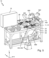
- the in Fig. 5 The processing device 10 shown is used for processing flat materials 12 extending along a material plane 11, which are in particular flexible and essentially impermeable to gas.
- Such flat materials 12 are, for example, paper or foils.
- the flat materials 12 can be formed in one or more layers, whereby the base material and/or the coating material can be made of plastic or metal.
- foils with a base material based on graphite and with a coating material based on copper or aluminum are to be produced. Due to the low thickness and flexible properties of the flat material 12, special requirements must be placed on the processing device 10.
- the processing device 10 has according to Fig. 5 a device housing 14 and a control cabinet 16. In the device housing 14, the processing device 10 a processing area 18 and a loading area 20. Furthermore, the processing device 10 has an x-axis X, a y-axis Y running perpendicular to the x-axis X and a z-axis Z running perpendicular to the x and y axes. In the loaded state, the material plane 11 of the flat material 12 runs parallel to the x-axis and the y-axis and perpendicular to the z-axis.
- the processing device 10 has according to the Fig. 3 and 4 a magazine 22 with a first magazine location 24 and a second magazine location 26.
- the magazine 22 can be rotated by means of a rotary drive 28 about a magazine axis 30 running parallel to the z-axis, so that one magazine location 24, 26 can be pivoted into a processing position in the processing area 18 and the other magazine location 24, 26 can be pivoted into a loading position in the loading area 20.
- the processing position and the loading position are arranged opposite one another along the y-axis.
- the magazine 22 can be rotated in such a way that both the first magazine location 24 and the second magazine location 26 can be pivoted outside the processing area 18 and outside the loading area 20 into an intermediate position.
- Each magazine location 24, 26 has a holding device 200 and a mouth-shaped clamping device 400. Accordingly, the holding device 200 and the clamping device 400 are pivoted with the associated magazine location 24, 26 into the processing position, the loading position or the intermediate position.
- the holding device 200 has according to Fig. 3 and 4 a base plate 202 and a work plate 204 arranged in the base plate 202.
- the work plate 204 comprises a ferromagnetic material, preferably iron.
- the base plate 202 and/or the work plate 204 preferably have the external dimensions of the flat material 12 to be processed along the x-axis and the y-axis.
- a plurality of magnetic vacuum devices 206, in particular in the form of a vacuum nozzle, and magnetic support modules 208, in particular in the form of a brush, are provided on the work plate 204, whereby these can be arranged individually depending on the movement path of the laser beam or the outer contour of the cut piece 1.
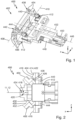
- the clamping device 400 comprises according to Fig. 1 and 2 two pairs of jaws 402 opposite each other along the x-axis, each pair of jaws 402 having an upper first jaw 404 and a lower second jaw 406.
- the first clamping jaw 402 and the second clamping jaw 404 extend parallel to a clamping axis 408, wherein the clamping axis 408 extends parallel to the y-axis.
- the first clamping jaw 404 and the second clamping jaw 406 can each be displaced in a rotational manner about a common clamping rotation axis 410 by means of at least one clamping rotation drive 412 between an open position and a closed position. In the open position, a flat material 12 can be inserted into the clamping device 400 and In the closed position, the flat material 12 is fixed and clamped in the clamping device 400.
- a flat material 12 In the open position, a flat material 12 can be inserted into the clamping device 400 and In the closed position, the flat material 12 is fixed and clamped in the clamping device 400.
- the open position (parallel to the z-axis), the closed position (parallel to the x-axis) and an intermediate position (45° to the x-axis and to the z-axis) of the clamping jaws 404, 406 are shown, with the first clamping jaw 404 pivoting upwards into the open position and the second clamping jaw 406 pivoting downwards into the open position.
- the clamping axis 408 and the clamping rotation axis 410 run parallel to the material plane 11.
- the first clamping jaw 404 has a first clamping surface 414 and the second clamping jaw 406 has a second clamping surface 416.
- the first clamping jaw 404 has a clamping element 418 that protrudes or is convex relative to the first clamping surface 414.
- the clamping element 418 is designed in the shape of a part circle.
- the clamping element 418 extends with a constant cross section along the clamping axis 408.
- the second clamping jaw 406 has a clamping recess 420 that is set back or concave relative to the second clamping surface 416.
- the clamping recess 420 is designed in the shape of a part circle, in particular complementary to the clamping element 418.
- the clamping recess 420 extends with a constant cross section along the clamping axis 408.
- the clamping element 418 and the clamping recess 420 are formed in one piece with the respective clamping jaw 404, 406.
- the clamping recess 420 accommodates the clamping element 418.
- the clamping element 418 engages in the clamping recess 420, so that a flat material 12 provided in the clamping device 400 is gripped and clamped at the same time. Due to the longer path that the flat material 12 has to travel in the area of the clamping element 418 and the clamping recess 420, gripping the flat material 12 also simultaneously clamps the flat material 12. This ensures that when the flat material 12 is secured in the clamping device 400, the conditions for safely processing the flat material 12 are already in place, in particular by preventing unwanted distortions or overlaps in the flat material 12 at least in the engagement area of a laser device 600.
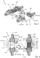
- the first clamping surface 414 has a first web section 422 and an adjoining first groove section 424, wherein the first groove section 424 is arranged between the first web section 422 and the clamping element 418.
- the first clamping surface 414 also has a second web section 426 and an adjoining second groove section 428, wherein the second groove section 428 is arranged between the second web section 426 and the clamping element 418.
- a groove section 424, 428 thus borders the clamping element 418 on both sides.
- the web sections 422, 426 and the groove sections 424, 428 extend parallel to the material plane 11 when the flat material 12 is gripped in the clamping device 400.
- the second clamping surface 416 has, in addition to the clamping recess 420, a first surface section 430 and a second surface section 432, wherein the clamping recess 420 is arranged between the surface sections 430, 432.
- the surface sections 430, 432 extend parallel to the material plane 11 when the flat material 12 is gripped in the clamping device 400.
- the first groove section 424 and the second groove section 428 each form a cavity 434 that is delimited in particular by the first clamping surface 414, the clamping element 418 and the associated web section 422, 426.
- the clamping element 418 and the clamping recess 420 can cause distortions and deformations on the flat material 12 in the area of the clamping element 418 and the clamping recess 420. If a gripping force is then exerted on this area in addition to the clamping element 418, the flat material 12 can be damaged and possibly tear.
- the flat material 12 can extend into the cavity 434 provided by the first groove section 424 and the second groove section 428 without being subjected to stress.
- the flat material 12 can therefore be gripped and clamped particularly gently.
- the flat material 12 is not contacted by the second clamping jaw 406.
- the first groove section 424 and the second groove section 428 are set back from the gripped flat material 12. If no flat material 12 is gripped, the first clamping jaw 404 and the second clamping jaw 406 in the closed position does not engage in the region of the first groove section 424 and the second groove section 428.
- Each clamping jaw 404, 406 comprises a first jaw lever 440 at a first jaw end 438 for coupling the clamping jaws 404, 406 to the at least one clamping rotation drive 412 and a second jaw lever 444 at a second jaw end 442 opposite the first jaw end 438 along the clamping axis 408.
- the jaw lever 440, 444 is arranged at its free end on a drive element of the clamping rotation drive 412 (not shown).
- the clamping jaws 404, 406 are not connected between the jaw levers 440, 444.
- One or two clamping rotation drives 412 can be provided per jaw end 438, 442 for pivoting the clamping jaws 404, 406 between the open position and the closed position.
- the clamping device 400 can be Fig. 1 and 3-4 be designed to be displaceable between a close position and a far position along a linear axis 446 running perpendicular to the clamping axis 408 by means of a clamping linear drive 448.
- the close position the pair of clamping jaws 402 are displaced towards the flat material 12 in order to reduce the tension of the fixed flat material 12.
- the far position the pair of clamping jaws 402 are displaced away from the flat material 12 in order to increase the tension of the fixed flat material 12.
- the clamping linear drive 448 has a clamping linear guide 450 and a linear slide 452 that can be moved on the clamping linear guide 450.
- the pair of clamping jaws 402 and the at least one clamping rotation drive 412 are arranged in or on the linear slide 452.
- the clamping axis 408 and the linear axis 446 run parallel to the material plane 11.
- the clamping device 400 For gripping and clamping a flat material 12 on both sides, the clamping device 400 comprises according to Fig. 3-5 two pairs of clamping jaws 402 opposite each other along the linear axis 446, wherein a first material side 466 of the flat material 12 is clamped in the first pair of clamping jaws and a second material side 468 opposite the first material side 466 along the x-axis is clamped in the second pair of clamping jaws 402.
- the respective clamping linear guide 450 is arranged with the linear slide 452 and the pair of clamping jaws 402 on a clamping frame 454.
- the clamping frame 454 has a first frame side 456 and a second frame side 458 opposite the first frame side 456, wherein a pair of clamping jaws 402 is provided for each frame side 456, 458.
- the clamping frame 454 has a first frame arm 460 and a second frame arm 462 as well as a frame arch 464 connecting the first frame arm 460 and the second frame arm 462.
- the first frame arm 460 is assigned to the first frame side 456 and the second frame arm 462 is assigned to the second frame side 458, with the clamping linear guide 450 on the frame arm 460, 462 is arranged.
- the holding device 200 for the flat material 12, a media supply (not shown), in particular a vacuum supply, and/or a sensor device (not shown) for checking whether and how a flat material 12 is tensioned can preferably be provided on the frame arch 464.
- the clamping frame 454 can also be Fig. 3 and 4 shown on the magazine 22 with several clamping devices 400. On the one hand, a first clamping frame 454 with two pairs of clamping jaws 402 is arranged on the magazine 22 and on the other hand, a further clamping frame 454 with two pairs of clamping jaws 402 is arranged on the magazine 22.
- the processing device 10 has the laser device 600.
- the laser device 600 is set up in such a way that a laser beam emitted by the laser device 600 and running essentially parallel to the z-axis is directed at the flat material 12 and an energy input into the flat material 12 occurs at an impact point, so that the flat material can be cut into a cut piece 1 and a scrap 2 at the impact point.
- the cut piece 1 is the product to be ultimately produced.
- the laser beam can preferably be moved over a working area, wherein the working area essentially corresponds to the longitudinal and transverse extension of the flat material 12.
- the laser device 600 preferably has an axis system 602 for displacing the laser beam along the x-axis by means of a first Linear axis 604 and along the y-axis by means of a second linear axis 606. It is also conceivable that the axis system 602 has a third linear axis (not shown) for displacement along the z-axis.
- the flat material 12, the cut piece 1 and the offcuts 2 can be transported by means of a transport device 800 according to Fig. 5 be handled.
Landscapes
- Engineering & Computer Science (AREA)
- Mechanical Engineering (AREA)
- Advancing Webs (AREA)
- Manipulator (AREA)
- Clamps And Clips (AREA)
Applications Claiming Priority (1)
| Application Number | Priority Date | Filing Date | Title |
|---|---|---|---|
| DE102023110267.2A DE102023110267A1 (de) | 2023-04-21 | 2023-04-21 | Spannvorrichtung und Bearbeitungsvorrichtung |
Publications (1)
| Publication Number | Publication Date |
|---|---|
| EP4450436A1 true EP4450436A1 (fr) | 2024-10-23 |
Family
ID=90789351
Family Applications (1)
| Application Number | Title | Priority Date | Filing Date |
|---|---|---|---|
| EP24170824.7A Pending EP4450436A1 (fr) | 2023-04-21 | 2024-04-17 | Dispositif de serrage et dispositif d'usinage |
Country Status (4)
| Country | Link |
|---|---|
| US (1) | US20240351170A1 (fr) |
| EP (1) | EP4450436A1 (fr) |
| DE (1) | DE102023110267A1 (fr) |
| MX (1) | MX2024004818A (fr) |
Citations (3)
| Publication number | Priority date | Publication date | Assignee | Title |
|---|---|---|---|---|
| KR102032416B1 (ko) * | 2019-02-25 | 2019-10-15 | 김용구 | 내열형 에어 클램프 장치 |
| CN111252319A (zh) * | 2020-03-18 | 2020-06-09 | 博众精工科技股份有限公司 | 用于液晶面板的撕膜机构 |
| CN112265255A (zh) * | 2020-09-29 | 2021-01-26 | 业成科技(成都)有限公司 | 膜夹具 |
Family Cites Families (7)
| Publication number | Priority date | Publication date | Assignee | Title |
|---|---|---|---|---|
| US3315301A (en) * | 1964-03-18 | 1967-04-25 | Arrem Plastics Inc | Apparatus for stretching sheet material |
| US4234174A (en) * | 1979-05-07 | 1980-11-18 | Angelo Cardono | Apparatus for aiding the cutting of a rubber mold |
| US4691905A (en) * | 1985-04-18 | 1987-09-08 | Nissan Motor Co., Ltd. | Machine for holding workpiece |
| DE202004001771U1 (de) * | 2004-02-05 | 2004-04-08 | Comau Germann-Intec Gmbh & Co. Kg | Spannvorrichtung, insbesondere Unterbau-Spannvorrichtung zum lösbaren Fixieren von Bauteilen |
| JP5503975B2 (ja) * | 2007-12-27 | 2014-05-28 | 株式会社カネカ | 延伸フィルムの製造方法 |
| DE102014007055A1 (de) * | 2014-05-15 | 2014-07-17 | MBH Metallbearbeitung e.k. | Vorrichtung zum Festspannen eines Gegenstandes |
| CN113573848B (zh) * | 2019-03-26 | 2023-11-10 | 菲斯科尔思品牌有限公司 | 具有层叠钳口的多功能工具 |
-
2023
- 2023-04-21 DE DE102023110267.2A patent/DE102023110267A1/de active Pending
-
2024
- 2024-04-17 EP EP24170824.7A patent/EP4450436A1/fr active Pending
- 2024-04-18 MX MX2024004818A patent/MX2024004818A/es unknown
- 2024-04-18 US US18/638,801 patent/US20240351170A1/en active Pending
Patent Citations (3)
| Publication number | Priority date | Publication date | Assignee | Title |
|---|---|---|---|---|
| KR102032416B1 (ko) * | 2019-02-25 | 2019-10-15 | 김용구 | 내열형 에어 클램프 장치 |
| CN111252319A (zh) * | 2020-03-18 | 2020-06-09 | 博众精工科技股份有限公司 | 用于液晶面板的撕膜机构 |
| CN112265255A (zh) * | 2020-09-29 | 2021-01-26 | 业成科技(成都)有限公司 | 膜夹具 |
Also Published As
| Publication number | Publication date |
|---|---|
| US20240351170A1 (en) | 2024-10-24 |
| DE102023110267A1 (de) | 2024-10-24 |
| MX2024004818A (es) | 2024-11-08 |
Similar Documents
| Publication | Publication Date | Title |
|---|---|---|
| DE112017003202B4 (de) | Werkstückhalter und Werkstückhalterbaugruppe für ein Nassbearbeitungssystem | |
| EP3191254B1 (fr) | Procédé de soudage et d'ablation laser de pièces | |
| CH697146A5 (de) | Greifvorrichtung zur Handhabung von Wafern. | |
| EP4486526A1 (fr) | Procédé et dispositif de séparation de pièces ouvrées | |
| DE102020115827A1 (de) | Verfahren zum Ver- und/oder Bearbeiten eines Stapels blattförmigen Guts sowie Schneidanlage | |
| EP2314393B1 (fr) | Presse dotée d'un dispositif de changement d'outil | |
| DE68918823T2 (de) | Vorrichtung zum Ausschneiden von Tab-Anordnungen und zum Formen von deren Anschlüssen. | |
| DE102010042777B4 (de) | Laserschneidanordnung und Verfahren zum Schneiden | |
| EP4450436A1 (fr) | Dispositif de serrage et dispositif d'usinage | |
| WO2000003830A1 (fr) | Dispositif pour l'usinage au laser de pieces plates | |
| DE69622224T2 (de) | Verfahren und Vorrichtung für Mechanismus zum genauen Abtrennen eines Angusses | |
| EP3398742B1 (fr) | Dispositif de sciage pour couper des pièces en forme de plaque | |
| EP0233137A1 (fr) | Equipement pour le soudage de feuilles métalliques empilées | |
| DE102017129142B4 (de) | Transporteinheit, Transportvorrichtung und Verfahren zum Transportieren eines Objektes sowie Vorrichtung und Verfahren zum Ausbilden mindestens eines Merkmals auf einem Objekt | |
| DE202010014971U1 (de) | Vorrichtung zum Biegen eines Anschlusskontakts eines Photovoltaikmoduls | |
| DE102023110266B4 (de) | Bearbeitungsvorrichtung und Verfahren zum Bearbeiten von Flachmaterial | |
| DE69732340T2 (de) | IC-Leiterrahmenverarbeitungssystem | |
| DE4022607A1 (de) | Einrichtung zum halten von frei positionierbaren bearbeitungs-hilfsmitteln | |
| DE2627058A1 (de) | Anschlagvorrichtung zum positionieren eines bleches auf einer werkzeugmaschine | |
| DE3114633C2 (fr) | ||
| DE10004676A1 (de) | Einspannvorrichtung zum Schweißen von Blechen | |
| EP4406890A1 (fr) | Dispositif, agencement et procédé de détachement automatisé d'un coussinet thermoconducteur d'une feuille support | |
| DE102005002595A1 (de) | Vorschubvorrichtung für plattenförmige Werkstücke, sowie Spannzange zur Verwendung bei einer solchen Vorschubvorrichtung | |
| DE102022104824A1 (de) | Verfahren zum Handhaben eines Stapels sowie Schneidanlage | |
| DE102023131417A1 (de) | Handhabungseinrichtung und Handhabungsverfahren zum Handhaben von einem plattenförmigen Material |
Legal Events
| Date | Code | Title | Description |
|---|---|---|---|
| PUAI | Public reference made under article 153(3) epc to a published international application that has entered the european phase |
Free format text: ORIGINAL CODE: 0009012 |
|
| STAA | Information on the status of an ep patent application or granted ep patent |
Free format text: STATUS: THE APPLICATION HAS BEEN PUBLISHED |
|
| AK | Designated contracting states |
Kind code of ref document: A1 Designated state(s): AL AT BE BG CH CY CZ DE DK EE ES FI FR GB GR HR HU IE IS IT LI LT LU LV MC ME MK MT NL NO PL PT RO RS SE SI SK SM TR |
|
| STAA | Information on the status of an ep patent application or granted ep patent |
Free format text: STATUS: REQUEST FOR EXAMINATION WAS MADE |
|
| 17P | Request for examination filed |
Effective date: 20250422 |