EP4446751A1 - Automatisierte analysevorrichtung - Google Patents
Automatisierte analysevorrichtung Download PDFInfo
- Publication number
- EP4446751A1 EP4446751A1 EP22903970.6A EP22903970A EP4446751A1 EP 4446751 A1 EP4446751 A1 EP 4446751A1 EP 22903970 A EP22903970 A EP 22903970A EP 4446751 A1 EP4446751 A1 EP 4446751A1
- Authority
- EP
- European Patent Office
- Prior art keywords
- reagent
- probe
- liquid level
- liquid
- automatic analyzer
- Prior art date
- Legal status (The legal status is an assumption and is not a legal conclusion. Google has not performed a legal analysis and makes no representation as to the accuracy of the status listed.)
- Pending
Links
Images




Classifications
-
- G—PHYSICS
- G01—MEASURING; TESTING
- G01N—INVESTIGATING OR ANALYSING MATERIALS BY DETERMINING THEIR CHEMICAL OR PHYSICAL PROPERTIES
- G01N35/00—Automatic analysis not limited to methods or materials provided for in any single one of groups G01N1/00 - G01N33/00; Handling materials therefor
- G01N35/10—Devices for transferring samples or any liquids to, in, or from, the analysis apparatus, e.g. suction devices, injection devices
- G01N35/1009—Characterised by arrangements for controlling the aspiration or dispense of liquids
-
- G—PHYSICS
- G01—MEASURING; TESTING
- G01F—MEASURING VOLUME, VOLUME FLOW, MASS FLOW OR LIQUID LEVEL; METERING BY VOLUME
- G01F23/00—Indicating or measuring liquid level or level of fluent solid material, e.g. indicating in terms of volume or indicating by means of an alarm
- G01F23/22—Indicating or measuring liquid level or level of fluent solid material, e.g. indicating in terms of volume or indicating by means of an alarm by measuring physical variables, other than linear dimensions, pressure or weight, dependent on the level to be measured, e.g. by difference of heat transfer of steam or water
- G01F23/26—Indicating or measuring liquid level or level of fluent solid material, e.g. indicating in terms of volume or indicating by means of an alarm by measuring physical variables, other than linear dimensions, pressure or weight, dependent on the level to be measured, e.g. by difference of heat transfer of steam or water by measuring variations of capacity or inductance of capacitors or inductors arising from the presence of liquid or fluent solid material in the electric or electromagnetic fields
- G01F23/263—Indicating or measuring liquid level or level of fluent solid material, e.g. indicating in terms of volume or indicating by means of an alarm by measuring physical variables, other than linear dimensions, pressure or weight, dependent on the level to be measured, e.g. by difference of heat transfer of steam or water by measuring variations of capacity or inductance of capacitors or inductors arising from the presence of liquid or fluent solid material in the electric or electromagnetic fields by measuring variations in capacitance of capacitors
-
- G—PHYSICS
- G01—MEASURING; TESTING
- G01F—MEASURING VOLUME, VOLUME FLOW, MASS FLOW OR LIQUID LEVEL; METERING BY VOLUME
- G01F23/00—Indicating or measuring liquid level or level of fluent solid material, e.g. indicating in terms of volume or indicating by means of an alarm
- G01F23/22—Indicating or measuring liquid level or level of fluent solid material, e.g. indicating in terms of volume or indicating by means of an alarm by measuring physical variables, other than linear dimensions, pressure or weight, dependent on the level to be measured, e.g. by difference of heat transfer of steam or water
- G01F23/26—Indicating or measuring liquid level or level of fluent solid material, e.g. indicating in terms of volume or indicating by means of an alarm by measuring physical variables, other than linear dimensions, pressure or weight, dependent on the level to be measured, e.g. by difference of heat transfer of steam or water by measuring variations of capacity or inductance of capacitors or inductors arising from the presence of liquid or fluent solid material in the electric or electromagnetic fields
- G01F23/263—Indicating or measuring liquid level or level of fluent solid material, e.g. indicating in terms of volume or indicating by means of an alarm by measuring physical variables, other than linear dimensions, pressure or weight, dependent on the level to be measured, e.g. by difference of heat transfer of steam or water by measuring variations of capacity or inductance of capacitors or inductors arising from the presence of liquid or fluent solid material in the electric or electromagnetic fields by measuring variations in capacitance of capacitors
- G01F23/265—Indicating or measuring liquid level or level of fluent solid material, e.g. indicating in terms of volume or indicating by means of an alarm by measuring physical variables, other than linear dimensions, pressure or weight, dependent on the level to be measured, e.g. by difference of heat transfer of steam or water by measuring variations of capacity or inductance of capacitors or inductors arising from the presence of liquid or fluent solid material in the electric or electromagnetic fields by measuring variations in capacitance of capacitors for discrete levels
-
- G—PHYSICS
- G01—MEASURING; TESTING
- G01F—MEASURING VOLUME, VOLUME FLOW, MASS FLOW OR LIQUID LEVEL; METERING BY VOLUME
- G01F23/00—Indicating or measuring liquid level or level of fluent solid material, e.g. indicating in terms of volume or indicating by means of an alarm
- G01F23/22—Indicating or measuring liquid level or level of fluent solid material, e.g. indicating in terms of volume or indicating by means of an alarm by measuring physical variables, other than linear dimensions, pressure or weight, dependent on the level to be measured, e.g. by difference of heat transfer of steam or water
- G01F23/26—Indicating or measuring liquid level or level of fluent solid material, e.g. indicating in terms of volume or indicating by means of an alarm by measuring physical variables, other than linear dimensions, pressure or weight, dependent on the level to be measured, e.g. by difference of heat transfer of steam or water by measuring variations of capacity or inductance of capacitors or inductors arising from the presence of liquid or fluent solid material in the electric or electromagnetic fields
- G01F23/263—Indicating or measuring liquid level or level of fluent solid material, e.g. indicating in terms of volume or indicating by means of an alarm by measuring physical variables, other than linear dimensions, pressure or weight, dependent on the level to be measured, e.g. by difference of heat transfer of steam or water by measuring variations of capacity or inductance of capacitors or inductors arising from the presence of liquid or fluent solid material in the electric or electromagnetic fields by measuring variations in capacitance of capacitors
- G01F23/266—Indicating or measuring liquid level or level of fluent solid material, e.g. indicating in terms of volume or indicating by means of an alarm by measuring physical variables, other than linear dimensions, pressure or weight, dependent on the level to be measured, e.g. by difference of heat transfer of steam or water by measuring variations of capacity or inductance of capacitors or inductors arising from the presence of liquid or fluent solid material in the electric or electromagnetic fields by measuring variations in capacitance of capacitors measuring circuits therefor
-
- G—PHYSICS
- G01—MEASURING; TESTING
- G01N—INVESTIGATING OR ANALYSING MATERIALS BY DETERMINING THEIR CHEMICAL OR PHYSICAL PROPERTIES
- G01N35/00—Automatic analysis not limited to methods or materials provided for in any single one of groups G01N1/00 - G01N33/00; Handling materials therefor
- G01N35/10—Devices for transferring samples or any liquids to, in, or from, the analysis apparatus, e.g. suction devices, injection devices
- G01N35/1002—Reagent dispensers
-
- G—PHYSICS
- G01—MEASURING; TESTING
- G01N—INVESTIGATING OR ANALYSING MATERIALS BY DETERMINING THEIR CHEMICAL OR PHYSICAL PROPERTIES
- G01N35/00—Automatic analysis not limited to methods or materials provided for in any single one of groups G01N1/00 - G01N33/00; Handling materials therefor
- G01N35/10—Devices for transferring samples or any liquids to, in, or from, the analysis apparatus, e.g. suction devices, injection devices
- G01N35/1009—Characterised by arrangements for controlling the aspiration or dispense of liquids
- G01N35/1011—Control of the position or alignment of the transfer device
-
- G—PHYSICS
- G01—MEASURING; TESTING
- G01N—INVESTIGATING OR ANALYSING MATERIALS BY DETERMINING THEIR CHEMICAL OR PHYSICAL PROPERTIES
- G01N35/00—Automatic analysis not limited to methods or materials provided for in any single one of groups G01N1/00 - G01N33/00; Handling materials therefor
- G01N35/10—Devices for transferring samples or any liquids to, in, or from, the analysis apparatus, e.g. suction devices, injection devices
- G01N35/1009—Characterised by arrangements for controlling the aspiration or dispense of liquids
- G01N35/1016—Control of the volume dispensed or introduced
-
- G—PHYSICS
- G01—MEASURING; TESTING
- G01N—INVESTIGATING OR ANALYSING MATERIALS BY DETERMINING THEIR CHEMICAL OR PHYSICAL PROPERTIES
- G01N35/00—Automatic analysis not limited to methods or materials provided for in any single one of groups G01N1/00 - G01N33/00; Handling materials therefor
- G01N35/10—Devices for transferring samples or any liquids to, in, or from, the analysis apparatus, e.g. suction devices, injection devices
- G01N35/1009—Characterised by arrangements for controlling the aspiration or dispense of liquids
- G01N35/1016—Control of the volume dispensed or introduced
- G01N2035/1018—Detecting inhomogeneities, e.g. foam, bubbles, clots
-
- G—PHYSICS
- G01—MEASURING; TESTING
- G01N—INVESTIGATING OR ANALYSING MATERIALS BY DETERMINING THEIR CHEMICAL OR PHYSICAL PROPERTIES
- G01N35/00—Automatic analysis not limited to methods or materials provided for in any single one of groups G01N1/00 - G01N33/00; Handling materials therefor
- G01N35/10—Devices for transferring samples or any liquids to, in, or from, the analysis apparatus, e.g. suction devices, injection devices
- G01N35/1009—Characterised by arrangements for controlling the aspiration or dispense of liquids
- G01N2035/1025—Fluid level sensing
Definitions
- the present invention relates to an automatic analyzer.
- Patent Document 1 JP-2020-112380-A
- an abnormality determination function of the automatic analyzer has been desired mainly for expensive large-size automatic analyzers introduced into large-scale facilities in developed countries. Meanwhile, in recent years, the introduction of the abnormality determination function has been desired also for small-size inexpensive automatic analyzers, and simultaneously has come to be desired also in emerging countries in which demands for small-size automatic analyzers are high.
- the present invention provides an automatic analyzer capable of reducing consumption of consumables produced at the time of reagent registration compared with conventional cases.
- an automatic analyzer including a probe dispensing a liquid accommodated in a container, a detection part detecting a liquid level of the liquid, and a judgment part causing the probe to descend in a direction toward the liquid and suspending the descent of the probe at a first position higher than a liquid level value assumed to be a height of the liquid level by a first predetermined value and, at the first position, determining that an abnormality does not exist in the liquid when the liquid level is not detected by the detection part, and determining that an abnormality exists in the liquid when the liquid level is detected by the detection part before the probe reaches the first position.
- a first embodiment of the automatic analyzer will be described with use of FIGs. 1 to 5 .
- FIG. 1 is a diagram schematically illustrating a plan view of the automatic analyzer.
- the automatic analyzer 101 includes a reagent disk 103, an RFID reader/writer 105, a dispensing unit 106, a washing tank 108, an incubator (reaction disk) 110, a chip sensor 112, a conveying unit 116, an interface 117, a controller 118, and so forth.
- reaction containers 109 into which a dispensed solution is discharged line up on a circumference in the incubator 110.
- the reaction containers 109 are used in common in all reactions and are disposable.
- the incubator 110 is controlled by a drive mechanism such as a motor in such a manner as to be rotationally driven by a distance equivalent to a length of a predetermined number of reaction containers 109 in one cycle.
- the reagent disk 103 for setting a plurality of reagent containers 102 is disposed on the analyzer.
- the reagent container 102 is composed of three reagent bottles 104 on one row.
- An IC tag 119 capable of contactless information communication by an RFID (Radio Frequency Identifier) is attached to an outer wall of the reagent container 102.
- One RFID reader/writer 105 for reading information in the IC tag 119 is disposed on the axis side of the reagent disk 103.
- specific reagent information such as the initial reagent filling amount recorded in the IC tag 119 is read by the RFID reader/writer 105 and whether or not the reagent container 102 is available is determined by a judgement part 118f of the controller 118 and is recorded in a storage part 118d.
- a reagent information file including reagent information is stored in the storage part 118d of the controller 118 in advance.
- the item ID of a reagent and the reagent filling amount corresponding to the reagent item in the reagent bottle 104 are described in the reagent information file.
- the dispensing unit 106 that can rotate and vertically move is installed between the incubator 110 and the reagent disk 103, and includes a probe 201 that can access the inside of the reagent bottle 104. Because the necessity to prevent contamination between reagents is high, a single-use disposable chip 111 is used for the dispensing unit 106 and dispensing is executed.
- the configuration of the dispensing unit 106 is illustrated in FIG. 2 .
- the dispensing unit 106 is composed of the probe 201, an arm 202, and an arm shaft 203.
- the arm shaft 203 is fixed to a base 204. This allows the probe 201 to rotate in a ⁇ -direction around the arm shaft 203.
- the configuration is made to allow the probe 201 to be vertically driven in a Z-direction. Based on this, the probe 201 executes dispensing operation, while moving in an arc around the rotation axis, of aspirating a reagent 205 accommodated in the reagent bottle 104 of the reagent container 102 and discharging the reagent 205 into the reaction container 109.
- the probe 201 has, in the arm 202, an electrostatic capacity sensor 206 for detecting change in the electrostatic capacity when the tip of the disposable chip 111 gets contact with the reagent 205 in the reagent container 102, and the position of the liquid level in the height direction can be checked.
- the probe 201 is manufactured by an electrically-conductive metal member, whereas the disposable chip 111 is manufactured by an electrically-conductive resin material.
- a chip sensor 112 for sensing whether or not the disposable chip 111 attached to the probe 201 exists is disposed around the operation trajectory of the probe 201 of the dispensing unit 106.
- the automatic analyzer 101 includes the conveying unit 116 that operates in X-, Y-, and Z-directions for conveying the disposable chip 111 from the magazine 115 to the chip supplying position 113.
- a reagent is aspirated by the disposable chip 111 mounted on the probe 201. Then, in the reaction container 109 set in the incubator 110, a sample dispensed into the reaction container 109 at a different timing in advance and the reagent are stirred and mixed by aspiration-discharge operation of the probe 201 or the disposable chip 111.
- the reaction container 109 that accommodates a reacted liquid resulting from the mixing of the sample and the reagent is managed at a predetermined temperature by the incubator 110, and reaction is promoted for a predetermined time.
- a spectrophotometer (illustration is omitted) for biochemical inspection is disposed around the incubator 110.
- the spectrophotometer measures the absorbance of a reacted liquid resulting from mixing of a sample and a reagent, by dispersing and detecting transmitted light obtained through irradiating the reacted liquid with a light source.
- the reacted liquid resulting from reaction for a predetermined time by the incubator 110 can be brought to a detection mechanism (illustration is omitted) for immunological inspection by a detector syringe (illustration is omitted) and be measured.
- a detection mechanism illustrated as a method for detecting a labeled substance
- electrochemiluminescence or chemiluminescence is employed as the principle.
- a second liquid container, a labeled substance, and the structure and properties of a detection area suitable for each are selected, and the amount of luminescence that derives from luminescence reaction of the labeled substance is measured with use of a photomultiplier tube as the detector.
- the reaction container 109 about which measurement of the absorbance has been completed in the incubator 110 is discarded to the chip discarding position 114 by the conveying unit 116.
- Each unit in the above-described automatic analyzer 101 is connected to the controller 118 through the interface 117.
- the controller 118 is a computer including a CPU, a memory, and so forth and is connected to pieces of equipment in the above-described automatic analyzer 101, and controls operation of the respective pieces of equipment and mechanisms in the automatic analyzer 101.
- FIG. 1 illustration is made with omission of the connection between the respective mechanisms that configure the automatic analyzer 101 and the controller 118 for simplification of illustration.
- the controller 118 is composed of an operating part 118a, a control part 118b, a display part 118c, the storage part 118d, a computing part 118e, and the judgement part 118f.
- the operating part 118a is operation equipment, such as a keyboard or mouse, operated when a user of the automatic analyzer 101 inputs some kind of instruction to the analyzer.
- the control part 118b controls rotational driving of the incubator 110, rotational operation of the reagent disk 103, operation of driving, reagent aspiration, and reagent discharge of the dispensing unit 106 including the probe 201, and so forth.
- the control of the operation of the respective pieces of equipment by the control part 118b is executed based on various programs recorded in the storage part 118d.
- control processing of operation executed in the control part 118b may be marshaled into one program or the respective kinds of control processing may be separated into a plurality of programs, or the control processing may be a combination of them.
- part or all of the programs may be implemented by dedicated hardware or may be modularized.
- the display part 118c is display equipment, such as a liquid crystal display, that displays, for an operator, an input screen of various parameters and setting, analysis inspection data of first inspection or re-inspection, a measurement result, and various kinds of information in the automatic analyzer 101, such as reagent information.
- the display part 118c can be made into a touch panel system that doubles as the control part 118b.
- the storage part 118d is formed of a storage medium such as an HDD or SSD in which various parameters input through the operating part 118a, information on a measurement-target sample (sample type information and so forth), measurement results, and so forth are stored besides various programs used for measurement of a sample.
- a storage medium such as an HDD or SSD in which various parameters input through the operating part 118a, information on a measurement-target sample (sample type information and so forth), measurement results, and so forth are stored besides various programs used for measurement of a sample.
- the storage part 118d stores information required to control the automatic analyzer 101, the current situation of the automatic analyzer 101, and so forth and affects operation of the controller 118.
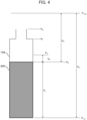
- the storage part 118d stores information on a first position P T higher than a liquid level value P 0 assumed to be the height of a liquid level to be described later by a first predetermined value D b , a second position P F higher than the first position P T by a second predetermined value, a third position P H higher than the second position P F by a third predetermined value, a fourth position higher than the third position P H by the third predetermined value, and so forth.
- the computing part 118e executes computation processing to obtain the concentration of a predetermined component in a sample from a detection result of the spectrophotometer or the detection mechanism.
- the computing part 118e is a part that determines whether the reagent container 102 can be used for sample measurement when reading of specific information of a reagent in the IC tag 119 read by the RFID reader/writer 105 has been normally executed. When the determination has been normally executed, the reagent container 102 is registered in the storage part 118d.
- the judgement part 118f causes the probe 201 to descend in the direction toward the reagent 205 and suspends the descent of the probe 201 at the first position P T higher than the liquid level value P 0 assumed to be the height of the liquid level by the first predetermined value D b .
- the judgement part 118f determines that an abnormality does not exist in the reagent 205 when the liquid level is not detected at the first position P T by the electrostatic capacity sensor 206, and determines that an abnormality exists in the reagent 205 when the liquid level is detected by the electrostatic capacity sensor 206 before the probe 201 reaches the first position P T . Details thereof will be described later.
- the automatic analyzer 101 is not limited to the form in which samples and reagents are stored in the same disk, and it is possible to employ a form in which they are stored in different dedicated disks.
- the dispensing unit one or more dispensing units exclusively for reagent dispensing and one or more dispensing units for sample dispensing can be each installed for exclusive use. It is desirable that the dispensing unit exclusively for the sample and the dispensing unit exclusively for the reagent are disposed, or operation parameters thereof are set in such a manner that operation thereof do not overlap with each other.
- the configuration of the automatic analyzer 101 is not limited to the form like that illustrated in FIG. 1 and can be made into an analyzer that executes analysis of various analysis items, such as an immunological analyzer that executes analysis of immunological analysis items or a biochemical analyzer that executes analysis of biochemical analysis items.
- the automatic analyzer 101 can be made into an analyzer that is additionally equipped with analysis equipment that measures another analysis item such as an electrolyte.
- the automatic analyzer 101 is not limited to the form in which it is made into a single analysis module configuration like that illustrated in FIG. 1 , and can be made into a configuration in which two or more modules, such as an analysis module that can measure various identical or different analysis items and a pretreatment module that executes pretreatment, are connected by a conveying unit.
- D r D m - D d . Because D m is a fixed value defined on the analyzer in advance, D r can be derived from D d .
- the shape of the reagent container 102 is defined, and conversion from the liquid level detection position (P d ) to a filling amount (V) of the reagent 205 can be made by a conversion expression.
- conversion to an initial liquid level position (P 0 ) obtained from an initial filling amount V 0 of the reagent 205 known in advance is made, and an abnormality of the liquid level state can be determined from the difference from the actual liquid level detection position (P d ) .
- the current state is identified as an abnormal liquid level rise attributed to bubble mixing and is determined as an abnormality.
- the probe 201 In the abnormality detection method using the above-described real liquid level detection position, the probe 201 needs to be brought into contact with the liquid level for liquid level sensing. Thus, the tip of the probe 201 needs to be washed every time in order to prevent the reagent 205 adhering to the probe 201 after liquid level detection from mixing into another reagent bottle 104 and carrying over.
- the disposable chip 111 In the case of mounting the disposable chip 111 on the tip of the probe 201 and executing abnormality detection, one or more disposable chips 111 are consumed. In addition, the disposable chip 111 needs to be replaced for each reagent bottle 104 in order to prevent the reagent 205 adhering to the disposable chip 111 from mixing into another reagent bottle 104 and carrying over. Alternatively, the tip of the disposable chip 111 needs to be washed by a washing liquid. Also in the case of the probe 201 on which the disposable chip 111 is not mounted on the tip (form of a second embodiment to be described later), the probe 201 needs to be washed after every liquid level detection in order to avoid the carry over between the reagent bottles 104, similarly.
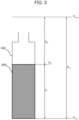
- the probe 201 descends to a position higher than P 0 by 3 [mm] in the direction from the liquid level toward the upper side.
- the probe 201 does not get contact with the reagent 205 in the reagent bottle 104 in the period from the start to the suspension of the descent operation.
- the judgement part 118f determines that an abnormality does not exist in the reagent bottle 104, for example, that a bubble or liquid film does not exist and the reagent bottle 104 is in a normal state, and it turns out that there is no problem in registration and use.
- the judgement part 118f considers that there is a high possibility that a bubble (foam) has been generated in the reagent 205, and determines that an abnormality exists.
- the judgement part 118f determines that an abnormality exists because there is a high possibility that a film-shaped bubble (film, liquid film) of the reagent 205 has been generated in the narrowed part of the inlet of the reagent bottle 104.
- the judgement part 118f determines that hovering has occurred, that is, an abnormality exists in the electrostatic capacity sensor 206, which is the liquid level detection mechanism.
- the initial filling amount V 0 varies depending on the kind of reagent, and therefore it is desirable to use information read from the IC tag 119, and it is assumed that the information varies for each kind of reagent.
- the first position P T , the second position P F , and the third position P H may not be varied depending on the kind of reagent. Alternatively, they may be varied for each kind of reagent or for each shape of the reagent bottle 104. They are not particularly limited.
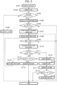
- FIG. 5 is a bubble detection workflow diagram in the case in which the disposable chip is used.
- the reagent container 102 In the automatic analyzer 101 like that in the present embodiment, the reagent container 102 according to an item of measurement of a sample needs to be recognized by the analyzer and be registered. Thus, as illustrated in FIG. 5 , reagent registration operation is started (step (hereinafter, described as "S") 101).
- the reagent container 102 is composed of three reagent bottles 104 as described above.
- the reagent disk 103 rotates and the reagent container 102 is conveyed to the position of the RFID reader/writer 105, and reading of the IC tag 119 of the reagent container 102 is started by the RFID reader/writer 105 (S102).
- the judgement part 118f determines whether or not the reading of the specific information has succeeded and a read item ID corresponds with an item ID stored in the storage part 118d in advance (S103).
- the processing is advanced to S105 when it is determined that the item IDs correspond with each other.
- the processing is advanced to S104 and an alarm is displayed on the display part 118c (S104), and the registration processing is completed.
- the judgement part 118f can read out the reagent filling amount unique to the reagent item, and updates the information of the IC tag 119 (S105) and determines whether or not the registration of the reagent is the initial registration (S106). When it is determined that the registration is not the initial registration, the reagent registration processing is ended.
- the probe 201 Upon the start of the bubble detection operation, the probe 201 is moved to the chip supplying position 113 and the disposable chip 111 is mounted (S108).
- the probe 201 on which the disposable chip 111 is mounted moves to the position of the chip sensor 112, and whether or not the disposable chip 111 exists is determined (S109).
- the reagent registration processing is ended.
- the probe 201 is moved to the aspiration position of the first reagent bottle 104 of the reagent container 102, and is caused to descend by a movement amount corresponding to the reagent filling amount of the first reagent bottle 104 (S110).
- the processing is advanced to S113 to make movement to the aspiration position of the second reagent bottle 104 (S113). Subsequently, the reagent disk 103 rotates to move the second reagent bottle 104 to the aspiration position of the second reagent bottle 104. Then, the processing is returned to S109 and the probe 201 moves to the chip sensor 112 and whether or not the chip exists is determined (S109). Then, the probe 201 descends by a movement amount corresponding to the reagent filling amount of the second reagent bottle 104 again (S110).
- the relevant reagent container 102 is deemed to be usable for measurement and is registered in the analyzer (S114), and the reagent registration operation is ended.
- the probe 201 starts bubble judgement operation of the first reagent bottle 104 of the second reagent container 102 without discarding the disposable chip 111. It is possible to execute bubble judgement by using the same disposable chip 111 similarly also when the third and subsequent reagents exist.
- an alarm is displayed on the display part 118c (S117), and it is indicated that bubble judgement has been made regarding the relevant reagent container 102, to display a message that prompts the user to take out the reagent container 102 and visually check the mixing of the bubble or film to remove it and execute reregistration.
- the automatic analyzer 101 of the above-described first embodiment includes the probe 201 that dispenses the reagent 205 to be accommodated in a container, the electrostatic capacity sensor 206 that detects the liquid level of the reagent 205, and the judgement part 118f that causes the probe 201 to descend in the direction toward the reagent 205 and suspends the descent of the probe 201 at the first position P T higher than the liquid level value P 0 assumed to be the height of the liquid level by the first predetermined value D b .
- the judgement part 118f determines that an abnormality does not exist in the reagent 205 when the liquid level has not been detected by the electrostatic capacity sensor 206 at the first position P T , and determines that an abnormality exists in the reagent 205 when the liquid level has been detected by the electrostatic capacity sensor 206 before the probe 201 reaches the first position P T .
- the frequency of washing of the probe 201 or the frequency of replacement of the disposable chip 111 at the time of reagent registration can be lowered compared with conventional cases and consumption of consumables can be reduced compared with conventional cases.
- the above-described configuration provides an effect that the occurrence of the washing time of the tip of the probe 201 or the replacement time of the disposable chip 111 after every determination can be suppressed and causing of delay of inspection can be reduced compared with conventional cases.
- the function of executing buddle detection at the time of reagent registration can be incorporated, execution of bubble judgement after measurement start can also be suppressed and more causing of delay of inspection can also be prevented.
- the judgement part 118f determines that a bubble has been generated in the reagent 205 when the liquid level is detected between the second position P F higher than the first position P T by the second predetermined value and the first position P T , and determines that a film of the reagent 205 has been generated when the liquid level is detected between the third position P H higher than the second position P F by the third predetermined value and the second position P F . Therefore, determination can be executed also regarding what kind of abnormality has occurred in the reagent bottle 104.
- the judgement part 118f determines that an abnormality exists in the liquid level detection function when the liquid level is detected between the fourth position higher than the third position P H by the third predetermined value and the third position P H . This allows the judgement part 118f to determine also whether or not an abnormality in the electrostatic capacity sensor 206 exists.
- FIG. 6 illustrates a bubble detection workflow in the case in which the probe in the automatic analyzer of the present second embodiment is used.
- the automatic analyzer of the present embodiment has a form in which the disposable chip 111 is not mounted on the tip of the probe 201 of the dispensing unit 106 of the automatic analyzer 101 described in the first embodiment and the probe 201 directly gets contact with the reagent 205.
- S201 to S206 illustrated in FIG. 6 are the same as S101 to S106 in FIG. 5 described in the first embodiment.
- bubble determination parameter check is executed (S207), and bubble detection operation is started (S208) with omission of mounting of the disposable chip 111 and determination of whether or not it is mounted differently from FIG. 5 .
- This S208 is the same as S107.
- S209 to S213 are the same as S110 to S114.
- the probe 201 is washed (S214), and the relevant reagent container 102 is masked without being registered (S215).
- S216 to S218 are the same as S117 to S119.
- the other configuration and operation are substantially the same configuration and operation as the automatic analyzer of the first embodiment and details thereof are omitted.
- a first round of bubble detection operation is executed for each reagent bottle 104. After it is determined that a bubble has been detected (yes of S210), the probe 201 is returned to the uppermost point without shifting the processing to S214, and a second round of bubble detection operation is executed for the reagent bottle 104 in which the bubble has been detected. Then, when a bubble is not detected in the second round of detection operation, the judgement part 118f determines that the bubble has been eliminated by the first round of bubble detection, and can allow the reagent of the relevant reagent bottle 104 to be unmasked.
- the bubble judgement accuracy can be improved by setting the bubble judgement distance D b regarding each reagent item.
- a reagent item with low content of a surfactant has low likelihood of formation of a large bubble in the reagent bottle 104.
- bubble detection also for a minuter bubble is enabled by changing D b from 3 [mm] to 2 [mm].
- bubble judgement parameter check is executed regarding each reagent before the start of bubble judgement operation, and a judgement threshold corresponding to the reagent item is read out to execute the bubble judgement operation.
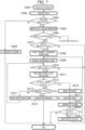
- FIGs. 7 and 8 illustrate a workflow of bubble detection in the case in which an installed reagent is used.
- the forms of the first embodiment and the second embodiment are the forms in which the probe 201 descends to the position higher than the assumed liquid level by the predetermined height and it is determined that a bubble is not mixed when the liquid level is not detected during the descent operation. As a precondition of this determination, it is assumed that the filling amount information of the reagent bottle 104 is stored in the storage part 118d or the IC tag 119 stuck to the reagent bottle 104.
- a reagent for analyzer installation evaluation is often used between different automatic analyzers as an index for determining whether the state at the time of analyzer installation is normal or abnormal. This reagent will be referred to as an installed reagent.
- the real reagent remaining amount has decreased compared with the reagent amount in the reagent filling amount information in the IC tag 119, and thus there is a possibility that divergence from the information of the IC tag 119 occurs.
- the control part 118b executes switching between the mode in which the probe 201 is brought into direct contact with the reagent 205 (see FIG. 3 ) and the mode in which the probe 201 is suspended at the first position P T (see FIG. 4 ) on the basis of whether or not the kind of reagent 205 is the installed reagent.
- S301 to S305 illustrated in FIG. 7 are the same as S101 to S105 illustrated in FIG. 5 .
- the judgement part 118f determines whether or not the reagent container 102 of the target is an installed reagent on the basis of the read specific information (S306).
- the processing is advanced to S307 when it is determined that the reagent container 102 is not an installed reagent.
- S307 to S320 are the same as S106 to S119.
- the disposable chip 111 is mounted (S322) and whether or not the disposable chip 111 exists is determined (S323). Then, the probe 201 is caused to descend until reaching the liquid level (S324).
- the judgement part 118f masks the relevant installed reagent without registering it (S330).
- the control part 118b moves the probe 201 to the chip discarding position 114 to discard the disposable chip 111 that has been used (S331).
- an alarm is displayed on the display part 118c (S332), and the registration processing is completed.
- the other configuration and operation are substantially the same configuration and operation as the automatic analyzer of the first embodiment, and details thereof are omitted.
- control part 118b executes switching between the mode in which the probe 201 is brought into direct contact with the reagent 205 and the mode in which the probe 201 is suspended at the first position P T .
- This allows the control part 118b to execute bubble judgement also regarding a reagent involving divergence between the initial filling amount information and the real liquid remaining amount, such as a reagent for analyzer inspection, as well as the bubble judgement function that can reduce consumption of consumables.
- control part 118b executes switching between the mode in which the probe 201 is brought into direct contact with the reagent 205 and the mode in which the probe 201 is suspended at the first position P T depending on the kind of reagent 205.
- the form in which switching is executed between the mode in which direct contact to a liquid is made and whether or not an abnormality exists is detected and the mode in which an abnormality is detected without contact to a liquid as in the present embodiment can be applied also to the form in which the probe 201 gets direct contact with a liquid without using the disposable chip 111 as in the second embodiment.
Landscapes
- Physics & Mathematics (AREA)
- General Physics & Mathematics (AREA)
- General Health & Medical Sciences (AREA)
- Analytical Chemistry (AREA)
- Pathology (AREA)
- Immunology (AREA)
- Biochemistry (AREA)
- Health & Medical Sciences (AREA)
- Life Sciences & Earth Sciences (AREA)
- Chemical & Material Sciences (AREA)
- Power Engineering (AREA)
- Engineering & Computer Science (AREA)
- Electromagnetism (AREA)
- Fluid Mechanics (AREA)
- Thermal Sciences (AREA)
- Automatic Analysis And Handling Materials Therefor (AREA)
Applications Claiming Priority (2)
| Application Number | Priority Date | Filing Date | Title |
|---|---|---|---|
| JP2021198882 | 2021-12-07 | ||
| PCT/JP2022/042161 WO2023106039A1 (ja) | 2021-12-07 | 2022-11-14 | 自動分析装置 |
Publications (2)
| Publication Number | Publication Date |
|---|---|
| EP4446751A1 true EP4446751A1 (de) | 2024-10-16 |
| EP4446751A4 EP4446751A4 (de) | 2025-12-03 |
Family
ID=86730391
Family Applications (1)
| Application Number | Title | Priority Date | Filing Date |
|---|---|---|---|
| EP22903970.6A Pending EP4446751A4 (de) | 2021-12-07 | 2022-11-14 | Automatisierte analysevorrichtung |
Country Status (5)
| Country | Link |
|---|---|
| US (1) | US20250027965A1 (de) |
| EP (1) | EP4446751A4 (de) |
| JP (1) | JP7720410B2 (de) |
| CN (1) | CN118302675A (de) |
| WO (1) | WO2023106039A1 (de) |
Family Cites Families (9)
| Publication number | Priority date | Publication date | Assignee | Title |
|---|---|---|---|---|
| JP3907819B2 (ja) * | 1998-03-23 | 2007-04-18 | オリンパス株式会社 | 液面検知装置 |
| JP3859555B2 (ja) * | 2002-06-24 | 2006-12-20 | オリンパス株式会社 | 自動分析装置 |
| US7482939B2 (en) | 2005-11-15 | 2009-01-27 | Roche Molecular Systems, Inc. | Electrical drop surveillance |
| JP5259550B2 (ja) * | 2009-10-27 | 2013-08-07 | 株式会社日立ハイテクノロジーズ | 自動分析装置およびサンプル分注方法 |
| JP2013148360A (ja) * | 2012-01-17 | 2013-08-01 | Hitachi High-Technologies Corp | 自動分析装置、分注機構および分注方法 |
| JP6919535B2 (ja) | 2017-12-05 | 2021-08-18 | 株式会社島津製作所 | 分注装置 |
| CN112585477B (zh) * | 2018-09-26 | 2024-02-23 | 株式会社日立高新技术 | 自动分析系统 |
| JP6837085B2 (ja) | 2019-01-09 | 2021-03-03 | 日本電子株式会社 | 自動分析装置及びプログラム |
| CN112881739B (zh) | 2019-11-29 | 2022-02-22 | 深圳市帝迈生物技术有限公司 | 加样方法及其装置、计算机存储介质、样本分析方法及其装置 |
-
2022
- 2022-11-14 US US18/711,999 patent/US20250027965A1/en active Pending
- 2022-11-14 JP JP2023566185A patent/JP7720410B2/ja active Active
- 2022-11-14 WO PCT/JP2022/042161 patent/WO2023106039A1/ja not_active Ceased
- 2022-11-14 CN CN202280077782.1A patent/CN118302675A/zh active Pending
- 2022-11-14 EP EP22903970.6A patent/EP4446751A4/de active Pending
Also Published As
| Publication number | Publication date |
|---|---|
| CN118302675A (zh) | 2024-07-05 |
| JP7720410B2 (ja) | 2025-08-07 |
| EP4446751A4 (de) | 2025-12-03 |
| US20250027965A1 (en) | 2025-01-23 |
| JPWO2023106039A1 (de) | 2023-06-15 |
| WO2023106039A1 (ja) | 2023-06-15 |
Similar Documents
| Publication | Publication Date | Title |
|---|---|---|
| JP7216815B2 (ja) | 自動分析装置、及びその洗浄方法 | |
| EP2293083B1 (de) | Automatisches analysegerät | |
| JP3990944B2 (ja) | 自動分析装置 | |
| US11965903B2 (en) | Automated analyzer and method of controlling automated analyzer | |
| JP7189339B2 (ja) | 自動分析装置 | |
| US20230204609A1 (en) | Automatic analysis apparatus and maintenance method in automatic analysis apparatus | |
| EP3896454B1 (de) | Automatisierter analysator | |
| JP7494375B2 (ja) | 自動分析装置、および自動分析装置における検体の吸引方法 | |
| EP3896456B1 (de) | Automatische analysevorrichtung und verfahren zur steuerung einer automatischen analysevorrichtung | |
| CN114137236B (zh) | 自动分析装置 | |
| EP4050342A1 (de) | Vorrichtung und verfahren zur automatischen analyse von reagenziendispension | |
| JP2006010363A (ja) | 自動分析装置 | |
| JPH10232234A (ja) | 自動分析装置 | |
| EP4446751A1 (de) | Automatisierte analysevorrichtung | |
| EP3578994A1 (de) | Automatischer analysator | |
| WO2016203919A1 (ja) | 自動分析装置 | |
| JP7358999B2 (ja) | 自動分析装置 | |
| JP7499881B2 (ja) | 自動分析装置 | |
| JP7189054B2 (ja) | 自動分析装置 | |
| EP4180818A1 (de) | Automatisierter analysator und wartungsverfahren für automatisierten analysator | |
| EP4379390A1 (de) | Automatische analysevorrichtung und führungsverfahren für die automatische analysevorrichtung | |
| JP7502226B2 (ja) | 自動分析装置 | |
| JP7798534B2 (ja) | 自動分析装置 | |
| JP7105112B2 (ja) | 分注ユニット、自動分析装置及び液面検出判定方法 | |
| JP2025144280A (ja) | 自動分析装置 |
Legal Events
| Date | Code | Title | Description |
|---|---|---|---|
| STAA | Information on the status of an ep patent application or granted ep patent |
Free format text: STATUS: THE INTERNATIONAL PUBLICATION HAS BEEN MADE |
|
| PUAI | Public reference made under article 153(3) epc to a published international application that has entered the european phase |
Free format text: ORIGINAL CODE: 0009012 |
|
| STAA | Information on the status of an ep patent application or granted ep patent |
Free format text: STATUS: REQUEST FOR EXAMINATION WAS MADE |
|
| 17P | Request for examination filed |
Effective date: 20240522 |
|
| AK | Designated contracting states |
Kind code of ref document: A1 Designated state(s): AL AT BE BG CH CY CZ DE DK EE ES FI FR GB GR HR HU IE IS IT LI LT LU LV MC ME MK MT NL NO PL PT RO RS SE SI SK SM TR |
|
| DAV | Request for validation of the european patent (deleted) | ||
| DAX | Request for extension of the european patent (deleted) | ||
| A4 | Supplementary search report drawn up and despatched |
Effective date: 20251104 |
|
| RIC1 | Information provided on ipc code assigned before grant |
Ipc: G01N 35/10 20060101AFI20251029BHEP Ipc: G01F 23/263 20220101ALI20251029BHEP |