EP4439733A1 - Matériau composite à base de silicium et son procédé de préparation, matériau d'électrode négative et batterie au lithium-ion - Google Patents
Matériau composite à base de silicium et son procédé de préparation, matériau d'électrode négative et batterie au lithium-ion Download PDFInfo
- Publication number
- EP4439733A1 EP4439733A1 EP22960426.9A EP22960426A EP4439733A1 EP 4439733 A1 EP4439733 A1 EP 4439733A1 EP 22960426 A EP22960426 A EP 22960426A EP 4439733 A1 EP4439733 A1 EP 4439733A1
- Authority
- EP
- European Patent Office
- Prior art keywords
- coating layer
- silicon
- carbon source
- ferro
- heat treatment
- Prior art date
- Legal status (The legal status is an assumption and is not a legal conclusion. Google has not performed a legal analysis and makes no representation as to the accuracy of the status listed.)
- Pending
Links
Images

Classifications
-
- H—ELECTRICITY
- H01—ELECTRIC ELEMENTS
- H01M—PROCESSES OR MEANS, e.g. BATTERIES, FOR THE DIRECT CONVERSION OF CHEMICAL ENERGY INTO ELECTRICAL ENERGY
- H01M4/00—Electrodes
- H01M4/02—Electrodes composed of, or comprising, active material
- H01M4/13—Electrodes for accumulators with non-aqueous electrolyte, e.g. for lithium-accumulators; Processes of manufacture thereof
- H01M4/139—Processes of manufacture
- H01M4/1395—Processes of manufacture of electrodes based on metals, Si or alloys
-
- C—CHEMISTRY; METALLURGY
- C22—METALLURGY; FERROUS OR NON-FERROUS ALLOYS; TREATMENT OF ALLOYS OR NON-FERROUS METALS
- C22C—ALLOYS
- C22C38/00—Ferrous alloys, e.g. steel alloys
- C22C38/02—Ferrous alloys, e.g. steel alloys containing silicon
-
- C—CHEMISTRY; METALLURGY
- C23—COATING METALLIC MATERIAL; COATING MATERIAL WITH METALLIC MATERIAL; CHEMICAL SURFACE TREATMENT; DIFFUSION TREATMENT OF METALLIC MATERIAL; COATING BY VACUUM EVAPORATION, BY SPUTTERING, BY ION IMPLANTATION OR BY CHEMICAL VAPOUR DEPOSITION, IN GENERAL; INHIBITING CORROSION OF METALLIC MATERIAL OR INCRUSTATION IN GENERAL
- C23C—COATING METALLIC MATERIAL; COATING MATERIAL WITH METALLIC MATERIAL; SURFACE TREATMENT OF METALLIC MATERIAL BY DIFFUSION INTO THE SURFACE, BY CHEMICAL CONVERSION OR SUBSTITUTION; COATING BY VACUUM EVAPORATION, BY SPUTTERING, BY ION IMPLANTATION OR BY CHEMICAL VAPOUR DEPOSITION, IN GENERAL
- C23C28/00—Coating for obtaining at least two superposed coatings either by methods not provided for in a single one of groups C23C2/00 - C23C26/00 or by combinations of methods provided for in subclasses C23C and C25C or C25D
- C23C28/04—Coating for obtaining at least two superposed coatings either by methods not provided for in a single one of groups C23C2/00 - C23C26/00 or by combinations of methods provided for in subclasses C23C and C25C or C25D only coatings of inorganic non-metallic material
-
- H—ELECTRICITY
- H01—ELECTRIC ELEMENTS
- H01M—PROCESSES OR MEANS, e.g. BATTERIES, FOR THE DIRECT CONVERSION OF CHEMICAL ENERGY INTO ELECTRICAL ENERGY
- H01M10/00—Secondary cells; Manufacture thereof
- H01M10/05—Accumulators with non-aqueous electrolyte
- H01M10/052—Li-accumulators
- H01M10/0525—Rocking-chair batteries, i.e. batteries with lithium insertion or intercalation in both electrodes; Lithium-ion batteries
-
- H—ELECTRICITY
- H01—ELECTRIC ELEMENTS
- H01M—PROCESSES OR MEANS, e.g. BATTERIES, FOR THE DIRECT CONVERSION OF CHEMICAL ENERGY INTO ELECTRICAL ENERGY
- H01M4/00—Electrodes
- H01M4/02—Electrodes composed of, or comprising, active material
- H01M4/36—Selection of substances as active materials, active masses, active liquids
- H01M4/362—Composites
- H01M4/366—Composites as layered products
-
- H—ELECTRICITY
- H01—ELECTRIC ELEMENTS
- H01M—PROCESSES OR MEANS, e.g. BATTERIES, FOR THE DIRECT CONVERSION OF CHEMICAL ENERGY INTO ELECTRICAL ENERGY
- H01M4/00—Electrodes
- H01M4/02—Electrodes composed of, or comprising, active material
- H01M4/36—Selection of substances as active materials, active masses, active liquids
- H01M4/38—Selection of substances as active materials, active masses, active liquids of elements or alloys
- H01M4/386—Silicon or alloys based on silicon
-
- H—ELECTRICITY
- H01—ELECTRIC ELEMENTS
- H01M—PROCESSES OR MEANS, e.g. BATTERIES, FOR THE DIRECT CONVERSION OF CHEMICAL ENERGY INTO ELECTRICAL ENERGY
- H01M4/00—Electrodes
- H01M4/02—Electrodes composed of, or comprising, active material
- H01M4/62—Selection of inactive substances as ingredients for active masses, e.g. binders, fillers
- H01M4/624—Electric conductive fillers
- H01M4/625—Carbon or graphite
-
- H—ELECTRICITY
- H01—ELECTRIC ELEMENTS
- H01M—PROCESSES OR MEANS, e.g. BATTERIES, FOR THE DIRECT CONVERSION OF CHEMICAL ENERGY INTO ELECTRICAL ENERGY
- H01M4/00—Electrodes
- H01M4/02—Electrodes composed of, or comprising, active material
- H01M2004/026—Electrodes composed of, or comprising, active material characterised by the polarity
- H01M2004/027—Negative electrodes
Definitions
- the present disclosure relates to the technical field of lithium ion batteries, specifically to a silicon-based composite and a preparation method thereof, an anode material, and a lithium ion battery.
- silicon-based materials both at home and abroad, with the main research methods being the nanometerization, compounding, and silico-oxygen compounding of silicon.
- introducing a metal compound as a second phase into silicon materials is an effective method to compound silicon with metals, forming a Si-M alloy system.
- silicon is dispersed in the alloy phase system, and the good ductility and conductivity of the alloy phase enhance the electrical performance of silicon materials.
- Ductility can be used to buffer the volume expansion effect of silicon matrix, and the conductivity can improve the ion migration rate, giving full play to the capacity.
- Ferrosilicon alloy material is a novel silicon-based anode material that conforms to such characteristics, the FeSix inside the material plays a buffering and conductivity enhancing role, so that it has better electrochemical performance compared with pure silicon materials, but still has a certain volume expansion effect, which leads to serious performance degradation and cannot meet practical use requirements.
- the main modification method for ferrosilicon alloy anode materials is carbon coating, which can limit expansion to some extent.
- the carbon shell of the ferrosilicon material modified solely by carbon coating is difficult to maintain structural stability for a long time, and will still crack and peel off after multiple cycles, leading to rapid capacity fading. Therefore, it is necessary to provide a new silicon-based composite that can effectively improve the above problems.
- the main object of the present disclosure is to provide a silicon-based composite and a preparation method thereof, an anode material, and a lithium ion battery, in order to solve the problems of poor cycle stability of battery caused by poor structural stability of silicon-based composite in the prior art, etc.
- a silicon-based composite which includes: a ferro-silicon alloy core layer; a first coating layer coated on the outer surface of the ferro-silicon alloy core layer; and a second coating layer coated on the outer surface of the first coating layer away from the ferro-silicon alloy core layer; wherein the material of the first coating layer includes carbon and the material of the second coating layer includes an oxide.
- the second coating layer is provided with a plurality of through-holes; preferably, the radial width of the through-hole is 50 nm to 800 nm, more preferably 50 nm to 150 nm; preferably, the porosity of the second coating layer is 5% to 20%; and preferably, the specific surface area of the second coating layer is 0.5 m 2 /g to 2 m 2 /g.
- the oxide is selected from one or more of diboron trioxide, phosphorus pentoxide, arsenic trioxide, or vanadium pentoxide.
- the ferro-silicon alloy core layer is in powdery form, and preferably the average particle size of the ferro-silicon alloy core layer is 0.5 ⁇ m to 2.5 ⁇ m; preferably, the weight content of the iron element in the ferro-silicon alloy core layer is 5 wt% to 15 wt%; preferably, the thickness of the first coating layer is 50 nm to 150 nm, more preferably 50 nm to 80 nm; and preferably, the thickness of the second coating layer is 10 nm to 100 nm, more preferably 50 nm to 80 nm.
- a preparation method of the aforementioned silicon-based composite includes the following steps: step S1, providing a ferro-silicon alloy core layer; and step S2, coating a first coating layer on the outer surface of the ferro-silicon alloy core layer, and coating a second coating layer on the outer surface of the first coating layer away from the ferro-silicon alloy core layer, thereby forming the silicon-based composite.
- step S1 includes: ball milling and mixing the ferro-silicon alloy and a ball milling medium to obtain a first slurry containing the ferro-silicon alloy core layer; preferably, the ball to powder ratio during the ball milling process is 16-20:1; preferably, the raw materials in the ball milling process also comprise a dispersant, more preferably the dispersant is selected from one or more of citric acid, sodium tripolyphosphate, or sodium metasilicate; and preferably, the ball milling medium is anhydrous ethanol and/or water.
- the ball milling medium is anhydrous ethanol and/or water.
- step S2 includes: step S21, mixing the first slurry and the carbon source under stirring to obtain a second slurry; step S22, drying the second slurry and then subjecting same to a first heat treatment in an inert gas atmosphere to obtain a first heat treatment product; step S23, mixing the first heat treatment product with an oxide, and then performing a second heat treatment in an inert gas atmosphere to obtain the silicon-based composite;
- the carbon source comprises a first carbon source and a second carbon source;
- the thermal decomposition temperature of the first carbon source is less than that of the second carbon source;
- the treatment temperature of the first heat treatment is greater than or equal to the thermal decomposition temperature of the first carbon source;
- the treatment temperature of the second heat treatment is greater than or equal to the thermal decomposition temperature of the second carbon source, and the treatment temperature of the second heat treatment is greater than or equal to the melting point of the oxide; and preferably, the difference between the thermal decomposition temperature of the second carbon source and the thermal decomposition temperature of the first carbon source is
- the first carbon source is one or more of asphalt, carboxymethyl cellulose, glucose, polyethylene glycol, or potato starch; preferably, the second carbon source is one or more of phenolic resin, polyimide resin, or bismaleimide resin; preferably, in the carbon source, the weight ratio of the first carbon source to the second carbon source is 4-8:1; preferably, the dosage of the carbon source is 30% to 45% by weight of the ferro-silicon alloy layer; preferably, the oxide is in powdery form, and the average particle size of the oxide is 50 nm to 500 mm, more preferably 50 nm to 100 nm; preferably, the dosage of the oxide is 30% to 80% by weight of the carbon source; preferably, the stirring is carried out under vacuum conditions at a stirring speed of 800 r/min to 2000 r/min; preferably, the treatment time of the first heat treatment is 1 h to 6 h; and preferably, the treatment time of the second heat treatment is 1 h to 9 h.
- the treatment temperature of the first heat treatment is 350°C to 450°C, and the treatment temperature of the second heat treatment is 800°C to 900°C; or, when the first carbon source is glucose and the oxide is phosphorus pentoxide, the treatment temperature of the first heat treatment is 250°C to 500°C, and the treatment temperature of the second heat treatment is 600°C to 1000°C; or, when the first carbon source is carboxymethyl cellulose and the oxide is vanadium pentoxide, the treatment temperature of the first heat treatment is 200°C to 300°C, and the treatment temperature of the second heat treatment is 600°C to 900°C.
- an anode material which comprises the aforementioned silicon-based composite or the silicon-based composite prepared by the aforementioned preparation method.
- a lithium ion battery which has the aforementioned anode material.
- the present disclosure uses ferro-silicon alloy as the core layer, and the FeSi x phase inner core can provide a buffer matrix to alleviate the volume change of silicon. Meanwhile, in the present disclosure, a first coating layer (with carbon included in the material) is provided on the outer surface of the core layer, and a second coating layer (with oxide included in the material) is coated on the outer surface of the first coating layer. In this way, the present application can further significantly improve the structural stability of the silicon-based composite while ensuring that the battery meets the conventional electrochemical performance of a battery (such as capacity performance and first charge-discharge efficiency), thereby improving the cycle stability of the battery, and enabling the battery to have superior capacity retention rate.
- a first coating layer with carbon included in the material
- a second coating layer with oxide included in the material
- the silicon-based composite in the prior art has problems such as poor cycle stability of battery caused by poor structural stability, etc.
- the present disclosure provides a silicon-based composite, which includes a ferro-silicon alloy core layer, a first coating layer, and a second coating layer, with the first coating layer being coated on the outer surface of the ferro-silicon alloy core layer, and the second coating layer being coated on the outer surface of the first coating layer away from the ferro-silicon alloy core layer; wherein the material of the first coating layer includes carbon and the material of the second coating layer includes an oxide.
- the present disclosure uses ferro-silicon alloy as the core layer, and the FeSi x phase inner core can provide a buffer matrix to alleviate the volume change of silicon. Meanwhile, in the present disclosure, a first coating layer (with carbon included in the material) is provided on the outer surface of the core layer, and a second coating layer (with oxide included in the material) is coated on the outer surface of the first coating layer. In this way, the present application can further significantly improve the structural stability of the silicon-based composite while ensuring that the battery meets the conventional electrochemical performance of a battery (such as capacity performance and first charge-discharge efficiency), thereby improving the cycle stability of the battery, and enabling the battery to have superior capacity retention rate.
- a first coating layer with carbon included in the material
- a second coating layer with oxide included in the material
- the material of the aforementioned first coating layer includes carbon, which as an intermediate layer can not only further improve the conductivity of the material, but also provide a buffer matrix for the ferro-silicon alloy core layer to further alleviate the volume change of the ferro-silicon alloy core layer, thereby improving both the electrical performance and cycle stability of the battery.
- the material of the aforementioned second coating layer is selected as oxide, which has higher mechanical properties and can effectively avoid the phenomenon of breakage and collapse of silicon-based composite, thereby further improving the structural stability of the silicon-based composite and thus mitigating the negative impact in the subsequent practical applications due to volume change, so that the cycle stability of battery can be greatly improved.
- the inventors of the present disclosure also found in the process of designing the above-mentioned double-layer coating structure that although the oxide coating layer can effectively improve the structural stability of the material, it can also lead to a slight decrease in the electrochemical performance of the material (such as capacity performance and first charge-discharge efficiency). Therefore, in a preferred embodiment, the present disclosure further provides a plurality of through-holes in the second coating layer.
- This through-hole structure is conducive to the immersion of electrolyte, enhancing the contact between silicon iron/carbon and electrolyte, and providing a transport channel for lithium ions, so that the ion conductivity of the material is enhanced, thereby improving the electrochemical performance of the battery, and thus allowing the battery to take into account both the excellent electrochemical performance and the cycle stability.
- the present disclosure uses ferro-silicon material as the core layer, and the internal FeSi x phase inner core provided a buffer matrix to alleviate the volume change of silicon.
- using carbon material as the first coating layer can enhance the conductivity of the material, maintain the structural stability, forming a conductive contact.
- an oxide is used as the second coating layer, and the second coating layer has a through-hole structure, which can improve the structural stability of the material and at the same time further provide a transport channel for the intercalation and de-intercalation of lithium ions.
- the silicon-based composite of the present disclosure can simultaneously balance excellent electrochemical performance and cycle stability.
- the oxide is selected from one or more of diboron trioxide, phosphorus pentoxide, arsenic trioxide, or vanadium pentoxide.
- the radial width of the through-hole in the second coating layer is 50 nm to 800 nm (more preferably 50 nm to 150 nm, for example 50 nm, 55 nm, 58 nm, 59 nm, 60 nm, 70 nm, 80 nm, 90 nm, 100 nm, 110 nm, 120 nm, 130 nm, 140 nm or 150 nm), the porosity of the second coating layer is 5% to 20% (for example 5%, 6%, 12%, 15%, 18% or 20%), and the specific surface area is 0.5 m 2 /g to 2 m 2 /g (for example 0.8 m 2 /g, 0.9 m 2 /g, 1.0 m 2 /g, 1.1 m 2 /g, 1.2
- the content of iron in the ferro-silicon alloy is 5 wt% to 15 wt% (for example 5 wt%, 10 wt%, or 15 wt%).
- the ferro-silicon alloy core layer is in powdery form, and the average particle size of the ferro-silicon alloy core layer is 0.5 ⁇ m to 2.5 ⁇ m (for example 0.5 ⁇ m, 1 ⁇ m, 1.5 ⁇ m, 2 ⁇ m or 2.5 ⁇ m).
- the internal stress of the material can be effectively reduced to avoid the phenomenon of expansion and pulverization caused by excessive particle size.
- the thickness of the first coating layer is 50 nm to 150 nm (more preferably 50 nm to 80 nm, for example 50 nm, 60 nm, 65 nm, 70 nm, 77 nm, 79 nm or 80 nm), and the thickness of the second coating layer is 10 nm to 100 nm (more preferably 50 nm to 80 nm, for example 75 nm, 76 nm, 77 nm, 78 nm or 80 nm).
- the present disclosure also provides a preparation method of the aforementioned silicon-based composite, which includes the following steps: step S1, providing a ferro-silicon alloy core layer; and step S2, coating a first coating layer on the outer surface of the ferro-silicon alloy core layer, and coating a second coating layer on the outer surface of the first coating layer away from the ferro-silicon alloy core layer, thereby forming the silicon-based composite.
- the present disclosure uses ferro-silicon alloy as the core layer, and the internal FeSi x phase inner core can provide a buffer matrix to alleviate the volume change of silicon.
- a first coating layer (with carbon included in the material) is provided on the outer surface of the core layer, and a second coating layer (with oxide included in the material) is coated on the outer surface of the first coating layer.
- the first coating layer serves as an intermediate layer, which can function to improve the conductivity of the material and further provide buffering for the ferro-silicon alloy core layer.
- the material of the second coating layer is selected as oxide, which has higher mechanical properties and can effectively avoid the phenomenon of breakage and collapse of silicon-based composite, thereby ensuring its structural stability and thus mitigating the negative impact due to volume change, so that the cycle stability of battery can be further improved.
- the above preparation method of the present disclosure is simple, has cost-effectiveness, and can achieve industrialization.
- the step S1 includes: ball milling and mixing the ferro-silicon alloy and a ball milling medium to obtain a first slurry containing the ferro-silicon alloy core layer.
- the ferro-silicon alloy and the ball milling medium are subjected to ball milling and mixing treatment, which can reduce the internal stress of the material and mitigate the phenomenon of expansion and pulverization caused by excessive particle size.
- tungsten carbide milling balls are used for ball milling and more preferably the particle size of the tungsten carbide milling balls is 2 mm to 6 mm. More preferably, the ball to powder ratio during the ball milling process is 16-20:1. More preferably, the ball milling medium is anhydrous ethanol and/or water.
- the raw materials in the ball milling process also comprise a dispersant, which is selected from one or more of citric acid, sodium tripolyphosphate, or sodium metasilicate.
- step S2 includes: step S21, mixing the first slurry and the carbon source under stirring to obtain a second slurry; step S22, drying the second slurry and then subjecting same to a first heat treatment in an inert gas atmosphere to obtain a first heat treatment product; step S23, mixing the first heat treatment product with an oxide, and then performing a second heat treatment in an inert gas atmosphere to obtain the silicon-based composite;
- the carbon source comprises a first carbon source and a second carbon source; the thermal decomposition temperature of the first carbon source is less than that of the second carbon source; the treatment temperature of the first heat treatment is greater than or equal to the thermal decomposition temperature of the first carbon source; the treatment temperature of the second heat treatment is greater than or equal to the thermal decomposition temperature of the second carbon source, and the treatment temperature of the second heat treatment is greater than or equal to the melting point of the oxide.
- two carbon sources with different decomposition temperatures are firstly added to the above ferro-silicon alloy core layer for stirring and mixing, the materials are evenly mixed so as to improve the subsequent coating effect.
- the first heat treatment is firstly performed at a lower treatment temperature in an inert gas atmosphere.
- the carbon source with a lower thermal decomposition temperature begins to decompose to form a uniform amorphous carbon coating layer on the surface of the core layer.
- an oxide is added and the second heat treatment is performed at a higher treatment temperature.
- the carbon source with a higher decomposition temperature in the first heat treatment begins to decompose, and release gas that passes through the melted liquid oxide and forms air pores on its surface.
- the silicon-based composite with the above structure is obtained.
- the difference between the thermal decomposition temperature of the second carbon source and the thermal decomposition temperature of the first carbon source is between 450°C and 550°C.
- the material prepared therefrom has three beneficial effects: firstly, the present disclosure uses ferro-silicon material as the core layer, and the internal FeSi x phase inner core can provide a buffer matrix to alleviate the volume change of silicon. Secondly, using carbon material as the first coating layer can enhance the conductivity of the material, maintain the structural stability, forming a conductive contact. Thirdly, an oxide is used as the second coating layer, and the second coating layer has a through-hole structure, which can improve the structural stability of the material and at the same time further provide a transport channel for the intercalation and de-intercalation of lithium ions. Based on the synergistic effect of the above-mentioned triple modification, the silicon-based composite of the present disclosure can simultaneously balance excellent electrochemical performance and cycle stability.
- the first carbon source is one or more of asphalt, carboxymethyl cellulose, glucose, polyethylene glycol, or potato starch.
- the second carbon source is one or more of phenolic resin, polyimide resin, or bismaleimide resin, further preferably phenolic resin and/or polyimide.
- the weight ratio of the first carbon source to the second carbon source is 4-8:1 (for example 4:1, 5:1, 6:1, 7:1 or 8:1).
- the dosage of the carbon source is 30% to 45% by weight of the ferro-silicon alloy, for example 30%, 40%, 43%, or 45%.
- the dosage of carbon source is below this range, it will lead to poor coating effect, decreased conductivity of material, and reduced specific capacity and rate performance of the battery.
- the dosage of carbon source is above this range, it will lead to a decrease in the proportion of active substances, resulting in a decrease in the specific capacity of the battery.
- the stirring is carried out under vacuum conditions at a stirring speed of 800 r/min to 2000 r/min.
- the treatment time of the first heat treatment is 1 h to 6 h, more preferably 1 h to 3 h; and the treatment time of the second heat treatment is 1 h to 9 h, more preferably 5 h to 9 h.
- the treatment temperature of the first heat treatment is 350°C to 450°C, more preferably 400°C to 450°C, and the treatment temperature of the second heat treatment is 800°C to 900°C, more preferably 850°C to 900°C; or, when the first carbon source is glucose and the oxide is phosphorus pentoxide, the treatment temperature of the first heat treatment is 250°C to 500°C, and the treatment temperature of the second heat treatment is 600°C to 1000°C; or, when the first carbon source is carboxymethyl cellulose and the oxide is vanadium pentoxide, the treatment temperature of the first heat treatment is 200°C to 300°C, and the treatment temperature of the second heat treatment is 600°C to 900°C.
- the second carbon sources are each independently selected from one or more of phenolic resin, polyimide resin, or bismaleimide resin.
- the present disclosure also provides an anode material, which comprises the aforementioned silicon-based composite or the silicon-based composite prepared by the aforementioned preparation method.
- an anode material which comprises the aforementioned silicon-based composite or the silicon-based composite prepared by the aforementioned preparation method.
- the structural stability of this anode material is superior.
- the present disclosure also provides a lithium ion battery, which has the aforementioned anode material.
- the lithium ion battery has better capacity and cycle retention rate.
- ferro-silicon alloy powder (the content of iron in the ferro-silicon alloy was 15 wt%) was weighed, and 500 mL of anhydrous ethanol was added as the ball milling medium at a ball to powder ratio of 18:1, which was subjected to ball milling at 500 r/min for 6 h to obtain a first slurry containing the ferro-silicon alloy core layer with a particle size of 1.6 ⁇ m.
- the carbon source was a powder mixture of asphalt and phenolic resin, and the two carbon sources were configured at a weight ratio of asphalt to phenolic resin of 8:1, which was stirred under vacuum at a stirring speed of 1,000 r/min for 1 h to obtain a second slurry.
- the second slurry obtained above was suction filtered and dried in a vacuum drying oven for 12 h, it was placed in a box furnace and subjected to the first heat treatment in an argon atmosphere, during which the temperature was raised to 450°C at a heating rate of 5°C/min and holding for 2 h, and then cooled down to room temperature in the furnace to obtain the first heat treatment product.
- the radial width of the through-hole was 55 nm
- the porosity of the second coating layer was 12%
- the specific surface area of the second coating layer was 0.9 m 2 /g.
- the thickness of the first coating layer was 80 nm
- the thickness of the second coating layer was 75 nm.
- Example 2 The difference between Example 2 and Example 1 only lied in that the carbon source was a powder mixture of asphalt and polyimide, and the two carbon sources were configured at a weight ratio of asphalt to polyimide of 8:1.
- the radial width of the through-hole was 60 nm
- the porosity of the second coating layer was 12%
- the specific surface area of the second coating layer was 1.1 m 2 /g.
- the thickness of the first coating layer was 79 nm
- the thickness of the second coating layer was 78 nm.
- Example 3 The difference between Example 3 and Example 1 only lied in that the carbon source was a powder mixture of asphalt and bismaleimide, and the two carbon sources were configured at a weight ratio of asphalt to bismaleimide of 8:1.
- Example 4 The difference between Example 4 and Example 2 only lied in that the two carbon sources were configured at a weight ratio of asphalt to polyimide of 6:1.
- the radial width of the through-hole was 110 nm
- the porosity of the second coating layer was 18%
- the specific surface area of the second coating layer was 1.8m 2 /g.
- the thickness of the first coating layer was 60 nm
- the thickness of the second coating layer was 79 nm.
- Example 5 The difference between Example 5 and Example 2 only lied in that the two carbon sources were configured at a weight ratio of asphalt to polyimide of 4:1.
- the radial width of the through-hole was 115 nm
- the porosity of the second coating layer was 20%
- the specific surface area of the second coating layer was 2.0m 2 /g.
- the thickness of the first coating layer was 50 nm
- the thickness of the second coating layer was 80 nm.
- Example 6 The difference between Example 6 and Example 2 only lied in that the addition amount of B 2 O 3 was 5 g.
- the radial width of the through-hole was 60 nm
- the porosity of the second coating layer was 12%
- the specific surface area of the second coating layer was 1.2m 2 /g.
- the thickness of the first coating layer was 80 nm
- the thickness of the second coating layer was 39 nm.
- Example 7 The difference between Example 7 and Example 2 only lied in that the treatment temperature of the first heat treatment was 300°C.
- the radial width of the through-hole was 59 nm
- the porosity of the second coating layer was 5%
- the specific surface area of the second coating layer was 2.0m 2 /g.
- the thickness of the first coating layer was 79 nm
- the thickness of the second coating layer was 38 nm.
- Example 8 The difference between Example 8 and Example 2 only lied in that the treatment temperature of the second heat treatment was 700°C.
- the radial width of the through-hole was 58 nm
- the porosity of the second coating layer was 8%
- the specific surface area of the second coating layer was 0.8m 2 /g.
- the thickness of the first coating layer was 70 nm
- the thickness of the second coating layer was 31 nm.
- Example 9 The difference between Example 9 and Example 2 only lied in that the dosage of carbon source was 14 g.
- the radial width of the through-hole was 50 nm
- the porosity of the second coating layer was 12%
- the specific surface area of the second coating layer was 1.0m 2 /g.
- the thickness of the first coating layer was 30 nm
- the thickness of the second coating layer was 76 nm.
- Example 10 The difference between Example 10 and Example 2 only lied in that the dosage of carbon source was 21 g.
- the radial width of the through-hole was 51 nm
- the porosity of the second coating layer was 12%
- the specific surface area of the second coating layer was 1.1 m 2 /g.
- the thickness of the first coating layer was 50 nm
- the thickness of the second coating layer was 75 nm.
- Example 11 The difference between Example 11 and Example 2 only lied in that the addition amount of B 2 O 3 was 24 g.
- the radial width of the through-hole was 46 nm
- the porosity of the second coating layer was 10%
- the specific surface area of the second coating layer was 0.9m 2 /g.
- the thickness of the first coating layer was 80 nm
- the thickness of the second coating layer was 100 nm.
- Example 12 The difference between Example 12 and Example 2 only lied in that the addition amount of B 2 O 3 was 16.5 g.
- the radial width of the through-hole was 110 nm
- the porosity of the second coating layer was 15%
- the specific surface area of the second coating layer was 1.3m 2 /g.
- the thickness of the first coating layer was 80 nm
- the thickness of the second coating layer was 80 nm.
- Example 13 The difference between Example 13 and Example 2 lied in that the first carbon source was carboxymethyl cellulose and the oxide was vanadium pentoxide.
- the treatment temperature of the first heat treatment was 300°C, and the treatment temperature of the second heat treatment was 900°C.
- the radial width of the through-hole was 105 nm
- the porosity of the second coating layer was 13%
- the specific surface area of the second coating layer was 1.3m 2 /g.
- the thickness of the first coating layer was 65 nm
- the thickness of the second coating layer was 76 nm.
- Example 14 The difference between Example 14 and Example 2 lied in that the first carbon source is glucose and the oxide is phosphorus pentoxide.
- the treatment temperature of the first heat treatment was 500°C, and the treatment temperature of the second heat treatment was 1000°C.
- the radial width of the through-hole was 100 nm
- the porosity of the second coating layer was 6%
- the specific surface area of the second coating layer was 0.8m 2 /g.
- the thickness of the first coating layer was 50 nm
- the thickness of the second coating layer was 78 nm.
- Example 15 The difference between Example 15 and Example 2 only lied in that the two carbon sources were configured at a weight ratio of asphalt to polyimide of 10:1.
- the radial width of the through-hole was 89 nm
- the porosity of the second coating layer was 4%
- the specific surface area of the second coating layer was 0.4m 2 /g.
- the thickness of the first coating layer was 76 nm
- the thickness of the second coating layer was 78 nm.
- Example 16 The difference between Example 16 and Example 2 only lied in that the carbon source was only asphalt.
- Comparative example 2 only lied in that no carbon source or boron oxide was added for sintered coating, only the ball milled ferro-silicon alloy core layer was used.
- the silicon-based composite includes a ferro-silicon alloy core layer, a first coating layer coated on the outer surface of the ferro-silicon alloy core layer; and a second coating layer coated on the outer surface of the first coating layer away from the ferro-silicon alloy core layer, wherein the second coating layer is provided with a plurality of through-holes.
- the reason for the formation of this pore structure is that during the first heat treatment, asphalt begins to pyrolyze to form amorphous carbon, which coats the ferro-silicon alloy core layer.
- polyimide does not undergo significant decomposition at this temperature, in the second heat treatment, when the temperature is heated to around 650°C, boron oxide begins to liquefy into a highly viscous liquid, and polyimide also begins to decompose in large quantities at this temperature, producing gas overflow, and many air pores are formed on boron oxide until it decomposes completely, and then the structure of the porous boron oxide shell is formed after the temperature is reduced.
- the anode materials prepared in the Examples and Comparative examples were made into 2032 button batteries, respectively to test the electrochemical performances of the materials.
- the current density of all batteries was 100 mA/g, and the voltage range was 0.01 V to 1.5 V.
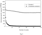
- Figure 3 shows a comparison diagram of the discharge cycle curves of batteries between Example 1 and Comparative example 2 of the present disclosure.
- Example 16 and Example 2 it can be found that the arrangement of a plurality of through-holes in the second coating layer can enable the product to exhibit better cycle stability, as well as excellent charge-discharge specific capacity and charge-discharge efficiency compared to the second coating layer without a through-hole structure, and thus allowing the product to take into account the better cycle stability, charge-discharge specific capacity and charge-discharge efficiency simultaneously.
- the weight ratio of the first carbon source to the second carbon source is preferably 4-8:1.
- the product can take into account the better cycle stability, charge-discharge specific capacity and charge-discharge efficiency simultaneously.
- the weight ratio of the first carbon source to the second carbon source is not within this range (such as in Example 15), the porosity of the product material is poor, and the charge-discharge specific capacity of the battery will be relatively low.
- the dosage of the oxide is preferably 30% to 80% by weight of the carbon source.
- the dosage of oxide is not within this range (such as Example 6), the cycle stability of the product is poor.
- the treatment temperature of the first heat treatment is preferably 350°C to 450°C, and the treatment temperature of the second heat treatment is 800°C to 900°C.
- the heat treatment temperature is not within this range (such as Example 7 and Example 8), the cycle stability of the product is poor.
- the dosage of the carbon source is preferably 30% to 45% by weight of the ferro-silicon alloy layer.
- the amount of carbon source is not within this range (such as Example 9), the cycle stability of the product is poor.
Landscapes
- Chemical & Material Sciences (AREA)
- Engineering & Computer Science (AREA)
- Chemical Kinetics & Catalysis (AREA)
- General Chemical & Material Sciences (AREA)
- Electrochemistry (AREA)
- Materials Engineering (AREA)
- Manufacturing & Machinery (AREA)
- Mechanical Engineering (AREA)
- Metallurgy (AREA)
- Organic Chemistry (AREA)
- Composite Materials (AREA)
- Inorganic Chemistry (AREA)
- Battery Electrode And Active Subsutance (AREA)
Applications Claiming Priority (1)
| Application Number | Priority Date | Filing Date | Title |
|---|---|---|---|
| PCT/CN2022/123606 WO2024065818A1 (fr) | 2022-09-30 | 2022-09-30 | Matériau composite à base de silicium et son procédé de préparation, matériau d'électrode négative et batterie au lithium-ion |
Publications (2)
| Publication Number | Publication Date |
|---|---|
| EP4439733A1 true EP4439733A1 (fr) | 2024-10-02 |
| EP4439733A4 EP4439733A4 (fr) | 2025-09-17 |
Family
ID=90475585
Family Applications (1)
| Application Number | Title | Priority Date | Filing Date |
|---|---|---|---|
| EP22960426.9A Pending EP4439733A4 (fr) | 2022-09-30 | 2022-09-30 | Matériau composite à base de silicium et son procédé de préparation, matériau d'électrode négative et batterie au lithium-ion |
Country Status (2)
| Country | Link |
|---|---|
| EP (1) | EP4439733A4 (fr) |
| WO (1) | WO2024065818A1 (fr) |
Family Cites Families (4)
| Publication number | Priority date | Publication date | Assignee | Title |
|---|---|---|---|---|
| US8585935B2 (en) * | 2009-06-03 | 2013-11-19 | Farasis Energy, Inc. | Composite for Li-ion cells and the preparation process thereof |
| KR20180027022A (ko) * | 2016-09-05 | 2018-03-14 | 지에스에너지 주식회사 | 이차전지용 음극활물질 및 이의 제조방법 |
| CN108346788B (zh) * | 2018-01-31 | 2021-01-15 | 广东省稀有金属研究所 | 一种碳包覆硅铁合金复合负极材料的制备方法 |
| CN111564611A (zh) * | 2020-04-07 | 2020-08-21 | 河南电池研究院有限公司 | 硅氧碳复合材料、制备方法及锂电池材料 |
-
2022
- 2022-09-30 EP EP22960426.9A patent/EP4439733A4/fr active Pending
- 2022-09-30 WO PCT/CN2022/123606 patent/WO2024065818A1/fr not_active Ceased
Also Published As
| Publication number | Publication date |
|---|---|
| WO2024065818A1 (fr) | 2024-04-04 |
| EP4439733A4 (fr) | 2025-09-17 |
Similar Documents
| Publication | Publication Date | Title |
|---|---|---|
| JP7288059B2 (ja) | シリコン酸素複合負極材料、その調製方法及びリチウムイオン電池 | |
| EP3496189B1 (fr) | Composé et son procédé de préparation, et utilisation dans une batterie rechargeable lithium-ion | |
| CN116682946A (zh) | 一种掺杂改性磷酸焦磷酸铁钠正极材料及制备方法 | |
| CN112271280B (zh) | 复合正极材料及其制备方法和锂离子电池 | |
| JP2022537501A (ja) | シリコン酸素複合負極材料、その製造方法及びリチウムイオン電池 | |
| CN105514432B (zh) | 一种磷酸铁锂复合正极材料及其制备方法 | |
| KR20220155344A (ko) | 산화 규소 복합 음극재 및 이의 제조 방법, 리튬 이온 전지 | |
| CN111477849B (zh) | 一种多孔Si/SiC/C材料的制备方法及负极材料 | |
| KR20230036949A (ko) | 리튬 함유 실리콘 산화물 복합 음극재 및 그 제조 방법과 리튬 이온 배터리 | |
| CN107706392B (zh) | 一种碳氮共包覆磷酸钒钠钠离子电池正极材料的制备方法 | |
| CN108346791A (zh) | 锂离子电池用硅/氮掺杂石墨烯复合材料制备方法及应用 | |
| CN106784833A (zh) | 硅碳负极材料及其制备方法 | |
| CN112242504B (zh) | 一种碳化硅包覆的空心硅材料、其制备方法以及使用该材料的电极和电化学装置 | |
| CN111244400A (zh) | 一种硅氧碳复合材料、锂离子电池及其制备方法、应用 | |
| CN115692644B (zh) | 一种pSi@CaO复合材料的制备方法及其在锂离子电池负极上的应用 | |
| CN116443841A (zh) | 一种铁基磷酸盐复合材料的制备方法、铁基磷酸盐复合材料及其应用 | |
| CN102339999B (zh) | 一种聚阴离子复合材料及其制备方法和用途 | |
| CN103618065B (zh) | 磷酸铁锂材料及其制备方法 | |
| CN117374257A (zh) | 磷酸焦磷酸铁钠碳复合正极材料及其制备方法与应用 | |
| CN115440982B (zh) | 一种锂电池用高性能硅碳负极材料及其制备方法 | |
| CN114843479A (zh) | 一种硅锡纳米材料及其制备方法和应用 | |
| EP4439733A1 (fr) | Matériau composite à base de silicium et son procédé de préparation, matériau d'électrode négative et batterie au lithium-ion | |
| CN115548302B (zh) | 硅基复合材料及其制备方法、负极材料、锂离子电池 | |
| CN118213510B (zh) | 铁基多孔碳钠离子电池复合负极材料及其制备方法 | |
| CN118431442A (zh) | 一种碳掺杂的多孔中熵合金锂离子电池负极材料及其制备方法 |
Legal Events
| Date | Code | Title | Description |
|---|---|---|---|
| STAA | Information on the status of an ep patent application or granted ep patent |
Free format text: STATUS: THE INTERNATIONAL PUBLICATION HAS BEEN MADE |
|
| PUAI | Public reference made under article 153(3) epc to a published international application that has entered the european phase |
Free format text: ORIGINAL CODE: 0009012 |
|
| STAA | Information on the status of an ep patent application or granted ep patent |
Free format text: STATUS: REQUEST FOR EXAMINATION WAS MADE |
|
| 17P | Request for examination filed |
Effective date: 20240626 |
|
| AK | Designated contracting states |
Kind code of ref document: A1 Designated state(s): AL AT BE BG CH CY CZ DE DK EE ES FI FR GB GR HR HU IE IS IT LI LT LU LV MC MK MT NL NO PL PT RO RS SE SI SK SM TR |
|
| REG | Reference to a national code |
Ref country code: DE Ref legal event code: R079 Free format text: PREVIOUS MAIN CLASS: H01M0004620000 Ipc: H01M0004360000 |
|
| A4 | Supplementary search report drawn up and despatched |
Effective date: 20250814 |
|
| RIC1 | Information provided on ipc code assigned before grant |
Ipc: H01M 4/36 20060101AFI20250808BHEP Ipc: H01M 4/62 20060101ALI20250808BHEP Ipc: H01M 4/38 20060101ALI20250808BHEP Ipc: C22C 38/02 20060101ALI20250808BHEP Ipc: C23C 28/04 20060101ALI20250808BHEP Ipc: H01M 4/1395 20100101ALI20250808BHEP Ipc: H01M 10/0525 20100101ALI20250808BHEP Ipc: H01M 4/02 20060101ALN20250808BHEP |
|
| DAX | Request for extension of the european patent (deleted) | ||
| RAV | Requested validation state of the european patent: fee paid |
Extension state: MA Effective date: 20240626 |