EP4438902A1 - Rotoranordnung einer elektronischen wasserpumpe und elektronische wasserpumpe - Google Patents
Rotoranordnung einer elektronischen wasserpumpe und elektronische wasserpumpe Download PDFInfo
- Publication number
- EP4438902A1 EP4438902A1 EP22895004.4A EP22895004A EP4438902A1 EP 4438902 A1 EP4438902 A1 EP 4438902A1 EP 22895004 A EP22895004 A EP 22895004A EP 4438902 A1 EP4438902 A1 EP 4438902A1
- Authority
- EP
- European Patent Office
- Prior art keywords
- bearing
- assembly
- rotor assembly
- cover plate
- bearing assembly
- Prior art date
- Legal status (The legal status is an assumption and is not a legal conclusion. Google has not performed a legal analysis and makes no representation as to the accuracy of the status listed.)
- Withdrawn
Links
Images



Classifications
-
- F—MECHANICAL ENGINEERING; LIGHTING; HEATING; WEAPONS; BLASTING
- F04—POSITIVE - DISPLACEMENT MACHINES FOR LIQUIDS; PUMPS FOR LIQUIDS OR ELASTIC FLUIDS
- F04D—NON-POSITIVE-DISPLACEMENT PUMPS
- F04D29/00—Details, component parts, or accessories
- F04D29/04—Shafts or bearings, or assemblies thereof
- F04D29/046—Bearings
-
- F—MECHANICAL ENGINEERING; LIGHTING; HEATING; WEAPONS; BLASTING
- F04—POSITIVE - DISPLACEMENT MACHINES FOR LIQUIDS; PUMPS FOR LIQUIDS OR ELASTIC FLUIDS
- F04D—NON-POSITIVE-DISPLACEMENT PUMPS
- F04D13/00—Pumping installations or systems
- F04D13/02—Units comprising pumps and their driving means
- F04D13/06—Units comprising pumps and their driving means the pump being electrically driven
-
- F—MECHANICAL ENGINEERING; LIGHTING; HEATING; WEAPONS; BLASTING
- F04—POSITIVE - DISPLACEMENT MACHINES FOR LIQUIDS; PUMPS FOR LIQUIDS OR ELASTIC FLUIDS
- F04D—NON-POSITIVE-DISPLACEMENT PUMPS
- F04D13/00—Pumping installations or systems
- F04D13/02—Units comprising pumps and their driving means
- F04D13/06—Units comprising pumps and their driving means the pump being electrically driven
- F04D13/0606—Canned motor pumps
- F04D13/0633—Details of the bearings
-
- F—MECHANICAL ENGINEERING; LIGHTING; HEATING; WEAPONS; BLASTING
- F04—POSITIVE - DISPLACEMENT MACHINES FOR LIQUIDS; PUMPS FOR LIQUIDS OR ELASTIC FLUIDS
- F04D—NON-POSITIVE-DISPLACEMENT PUMPS
- F04D29/00—Details, component parts, or accessories
-
- F—MECHANICAL ENGINEERING; LIGHTING; HEATING; WEAPONS; BLASTING
- F04—POSITIVE - DISPLACEMENT MACHINES FOR LIQUIDS; PUMPS FOR LIQUIDS OR ELASTIC FLUIDS
- F04D—NON-POSITIVE-DISPLACEMENT PUMPS
- F04D29/00—Details, component parts, or accessories
- F04D29/02—Selection of particular materials
- F04D29/026—Selection of particular materials especially adapted for liquid pumps
-
- F—MECHANICAL ENGINEERING; LIGHTING; HEATING; WEAPONS; BLASTING
- F04—POSITIVE - DISPLACEMENT MACHINES FOR LIQUIDS; PUMPS FOR LIQUIDS OR ELASTIC FLUIDS
- F04D—NON-POSITIVE-DISPLACEMENT PUMPS
- F04D29/00—Details, component parts, or accessories
- F04D29/04—Shafts or bearings, or assemblies thereof
- F04D29/043—Shafts
- F04D29/044—Arrangements for joining or assembling shafts
-
- F—MECHANICAL ENGINEERING; LIGHTING; HEATING; WEAPONS; BLASTING
- F04—POSITIVE - DISPLACEMENT MACHINES FOR LIQUIDS; PUMPS FOR LIQUIDS OR ELASTIC FLUIDS
- F04D—NON-POSITIVE-DISPLACEMENT PUMPS
- F04D29/00—Details, component parts, or accessories
- F04D29/04—Shafts or bearings, or assemblies thereof
- F04D29/046—Bearings
- F04D29/047—Bearings hydrostatic; hydrodynamic
- F04D29/0473—Bearings hydrostatic; hydrodynamic for radial pumps
-
- F—MECHANICAL ENGINEERING; LIGHTING; HEATING; WEAPONS; BLASTING
- F04—POSITIVE - DISPLACEMENT MACHINES FOR LIQUIDS; PUMPS FOR LIQUIDS OR ELASTIC FLUIDS
- F04D—NON-POSITIVE-DISPLACEMENT PUMPS
- F04D29/00—Details, component parts, or accessories
- F04D29/18—Rotors
- F04D29/22—Rotors specially for centrifugal pumps
- F04D29/24—Vanes
-
- F—MECHANICAL ENGINEERING; LIGHTING; HEATING; WEAPONS; BLASTING
- F04—POSITIVE - DISPLACEMENT MACHINES FOR LIQUIDS; PUMPS FOR LIQUIDS OR ELASTIC FLUIDS
- F04D—NON-POSITIVE-DISPLACEMENT PUMPS
- F04D29/00—Details, component parts, or accessories
- F04D29/40—Casings; Connections of working fluid
- F04D29/42—Casings; Connections of working fluid for radial or helico-centrifugal pumps
-
- F—MECHANICAL ENGINEERING; LIGHTING; HEATING; WEAPONS; BLASTING
- F04—POSITIVE - DISPLACEMENT MACHINES FOR LIQUIDS; PUMPS FOR LIQUIDS OR ELASTIC FLUIDS
- F04D—NON-POSITIVE-DISPLACEMENT PUMPS
- F04D29/00—Details, component parts, or accessories
- F04D29/60—Mounting; Assembling; Disassembling
- F04D29/62—Mounting; Assembling; Disassembling of radial or helico-centrifugal pumps
-
- F—MECHANICAL ENGINEERING; LIGHTING; HEATING; WEAPONS; BLASTING
- F04—POSITIVE - DISPLACEMENT MACHINES FOR LIQUIDS; PUMPS FOR LIQUIDS OR ELASTIC FLUIDS
- F04D—NON-POSITIVE-DISPLACEMENT PUMPS
- F04D29/00—Details, component parts, or accessories
- F04D29/60—Mounting; Assembling; Disassembling
- F04D29/62—Mounting; Assembling; Disassembling of radial or helico-centrifugal pumps
- F04D29/628—Mounting; Assembling; Disassembling of radial or helico-centrifugal pumps especially adapted for liquid pumps
-
- F—MECHANICAL ENGINEERING; LIGHTING; HEATING; WEAPONS; BLASTING
- F05—INDEXING SCHEMES RELATING TO ENGINES OR PUMPS IN VARIOUS SUBCLASSES OF CLASSES F01-F04
- F05D—INDEXING SCHEME FOR ASPECTS RELATING TO NON-POSITIVE-DISPLACEMENT MACHINES OR ENGINES, GAS-TURBINES OR JET-PROPULSION PLANTS
- F05D2240/00—Components
- F05D2240/50—Bearings
Definitions
- the rotor assembly is the core component of the electronic water pump.
- the rotor assembly When the electronic water pump is in operation, the rotor assembly is energized and converts its own mechanical energy into the kinetic energy of the fluid.
- the quality of the rotor assembly seriously affects the efficiency of the electronic water pump. For example, if the dynamic balance accuracy of the rotor assembly is poor, it will cause vibration of the electronic water pump, reduce the service life of the electronic water pump, and cause greater noise and environmental pollution.
- a rotor assembly of an electronic water pump including:
- the bearing assembly includes a shaft sleeve, and the impeller seat has a bushing extending along the axial direction of the shaft sleeve and fitting with a hole wall of the first central through hole.
- a material of the impeller seat includes polyphenylene sulfide.
- the bearing assembly includes a shaft sleeve and a bearing
- the bearing is a graphite bearing.
- one of an outer wall of the bearing and an inner wall of the shaft sleeve has a groove, and the other has a protrusion limited in the groove.
- At least one of an outer wall of the bearing and an outer wall of the shaft sleeve has the first limiting part.
- a side wall of the end of the bearing assembly has a plurality of first limiting parts in a circumferential direction
- the impeller seat has an embedded groove accommodating a first end of the bearing assembly
- a groove wall of the embedded groove has a plurality of second limiting parts in the circumferential direction
- the plurality of second limiting parts are respectively limited within the plurality of the first limiting parts.
- the magnetic ring assembly includes an iron core assembly, a first cover plate, a second cover plate and a sleeve;
- an electronic water pump including a housing and the rotor assembly according to the above aspect; the housing has an inner cavity and a rotation shaft located in the inner cavity, and the rotor assembly is accommodated in the inner cavity and is rotatably sleeved on the rotation shaft.
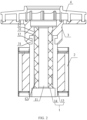
- the coaxiality between the magnetic ring assembly and the bearing assembly is ensured by the interference-fit between the magnetic ring assembly and the bearing assembly, and then the magnetic ring assembly and the bearing assembly which are interference-fitted are connected to the impeller seat. Therefore, in the embodiments of the present disclosure, the number of insert injection molding processes is reduced when manufacturing the rotor assembly, thereby ensuring the dynamic balancing accuracy of the rotor assembly, avoiding vibration of the electronic water pump with the rotor assembly during operation, prolonging the service life of the electronic water pump, and at the same time avoiding the generation of noise that causes pollution to the environment.
- the impeller seat 3 wraps the end of the bearing assembly 1, and the impeller seat 3 has a second limiting part 31 in limiting fit with the first limiting part 12 for limiting purpose.
- the impeller cover 4 is fixedly connected to a side of the impeller seat 3 away from the bearing assembly 1.
- the coaxiality between the magnetic ring assembly 2 and the bearing assembly 1 is ensured through the interference-fit between the magnetic ring assembly 2 and the bearing assembly 1, and then the magnetic ring assembly 2 and the bearing assembly 1 which are interference-fitted are connected to the impeller seat 3. Therefore, in the embodiment of the present disclosure, the number of insert injection molding processes can be reduced when the rotor assembly is produced, thereby ensuring the dynamic balance accuracy of the rotor assembly, avoiding vibration of the electronic water pump with the rotor assembly during operation, and extending the service life of the electronic water pump while avoiding noise pollution to the environment.
- the relative rotation between the bearing assembly 1 and the impeller seat 3 can be limited by the cooperation of the first limiting part 12 and the second limiting part 31, thereby avoiding the phenomenon of slipping between the bearing assembly 1 and the impeller seat 3, and ensuring the efficiency of the rotor assembly.
- the first limiting part 12 is a limiting groove
- the second limiting part 31 is a limiting block; or, the first limiting part 12 is a limiting block, and the second limiting part 31 is a limiting groove, as long as a limit fit of the first limiting part 12 and the second limiting part 31 can be realized, and the embodiment of the present disclosure is not limited to this.
- the first end of the bearing assembly 1 extends out of the magnetic ring assembly 2, and the second end of the bearing assembly 1 extends out of the magnetic ring assembly 2 or is flush with the end surface of the magnetic ring assembly 2.
- the impeller cover 4 and the impeller seat 3 are welded and fixed. Specifically, the impeller cover 4 and the impeller seat 3 are fixed by ultrasonic welding. Of course, other connection methods are also possible, as long as the fixed connection between the impeller cover and the impeller seat can be achieved, and the embodiment of the present disclosure is not limited to this.
- the magnetic ring assembly 2 mainly includes an iron core assembly 21.
- the iron core assembly 21 has a second central through hole.
- the iron core assembly 21 is sleeved on the bearing assembly 1 based on the second central through hole.
- the iron core assembly 21 is interference-fitted with the bearing assembly 1 to ensure the coaxiality between the iron core assembly 21 and the bearing assembly 1.
- the iron core assembly 21 includes the above-mentioned iron core and magnetic steel.
- the iron core and the magnetic steel can be produced in advance through an one-piece molding process to ensure the coaxiality of the iron core and the magnetic steel.
- the one-piece molding process of the iron core and the magnetic steel can refer to the related art.
- the iron core and the magnetic steel can also be obtained through other processes, as long as the coaxiality of the iron core and the magnetic field can be ensured, and the embodiment of the present disclosure is not limited to this.
- a sealing cavity for accommodating the iron core assembly 21 can be formed, so as to achieve the sealing protection of the iron core assembly 21.
- connection between the first cover plate 22 the bearing assembly 1, the connection between the second cover plate 23 and the bearing assembly 1, the connection between the first cover plate 22 and the sleeve 24, and the connection between the second cover plate 23 and the sleeve 24 can be welded. Specifically, laser welding can be used. Of course, other connection methods are also possible, as long as the sealing protection of the iron core assembly 21 can be achieved, and the embodiment of the present disclosure is not limited to this.
- the bearing assembly 1 includes a shaft sleeve 13.
- the shaft sleeve 13 has a first central through hole 11, and the end of the shaft sleeve 13 has a first limiting part 12.
- the shaft sleeve 13 is configured to be rotatably sleeved on the rotating shaft.
- the shaft sleeve 13 can be configured as an embedded part, and the impeller seat 3 is formed on the end of the shaft sleeve 13 through an insert injection molding process.
- the impeller seat 3 can also be obtained by pre-injection molding, and then the impeller seat 3 is connected to the end of the shaft sleeve 13 while ensuring the limiting fit of the first limiting part 12 and the second limiting part 31.
- a bushing 32 is also formed on the inner wall of the first central through hole 11. That is to say, the impeller seat 3 has a bushing 32 extending along the axial direction of the shaft sleeve 13 and fitting with the hole wall of the first central through hole 11. In this way, when the rotor assembly rotates, the bushing 32 is in direct contact with the rotating shaft and rotates relatively, thereby avoiding contact between the shaft sleeve 13 and the rotating shaft.
- the material of the impeller seat 3 includes PPS (Polyphenylene sulphide).
- the bearing assembly 1 includes a shaft sleeve 13 and a bearing 14.
- the bearing 14 has a first central through hole 11.
- the shaft sleeve 13 is sleeved on the bearing 14 and interference-fitted with the bearing 14.
- the impeller seat 3 wraps at least one of the end of the bearing 14 and the end of the shaft sleeve 13.
- the interference-fit between the shaft sleeve 13 and the bearing 14 can ensure the coaxiality of the shaft sleeve 13 and the bearing 14 to ensure the dynamic balance accuracy of the rotor assembly.
- the bearing 14 is configured to be rotatable limited on the rotating shaft.
- the first end of the bearing 14 and/or the first end of the shaft sleeve 13 can be injection molded as an embedded part to obtain the impeller seat 3.
- At least one of the outer wall of the bearing 14 and the outer wall of the shaft sleeve 13 has a first limiting part 12.
- the outer wall of the bearing 14 and the outer wall of the shaft sleeve 13 can be specifically determined according to the positional relationship between the bearing 14 and the shaft sleeve 13.
- the first end of the bearing 14 extends out of the first end of the shaft sleeve 13. At this time, the first end of the bearing 14 is wrapped by the impeller seat 3, and the first end of the bearing 14 has a first limiting part 12, so that the first limiting part 12 of the bearing 14 cooperates with the second limiting part 31 on the impeller seat 3 for limiting purpose.
- the first limiting part 12 of the bearing 14 cooperates with the second limiting part 31 on the impeller seat 3 for limiting purpose.
- the first end of the bearing 14 and the first end of the shaft sleeve 13 are both wrapped by the impeller seat 3, and the first end of the bearing 14 and the first end of the shaft sleeve 13 both have a first limiting part 12, so that the first limiting part 12 on the shaft sleeve 13 and the first limiting part 12 on the bearing 14 cooperate with the second limiting part 31 on the impeller seat 3 for limiting purpose.
- the first end of the bearing 14 does not extend out of the first end of the shaft sleeve 13.
- the first end of the shaft sleeve 13 is wrapped by the impeller seat 3, and the first end of the shaft sleeve 13 has a first limiting part 12, so that the first limiting part 12 at the first end of the shaft sleeve 13 cooperates with the second limiting part 31 on the impeller seat 3 for limiting purpose.
- first limiting parts 12 are provided on the outer side walls of the bearing 14 near both ends to prevent reverse mounting when the bearing 14 is assembled with the shaft sleeve 13, thus improving the assembly efficiency.
- the material of the bearing 14 is graphite, that is, the bearing 14 is a graphite bearing.
- one of the outer wall of the bearing 14 and the inner wall of the shaft sleeve 13 has a groove, and the other has a protrusion limited in the groove. In this way, through the cooperation of the groove and the protrusion, the contact area between the shaft sleeve 13 and the bearing 14 is increased, and at the same time, the relative rotation of the shaft sleeve 13 and the bearing 14 is further prevented.
- the side wall of the end of the bearing assembly 1 has a plurality of first limiting parts 12 in the circumferential direction, and the impeller seat 3 has an embedded groove that accommodates the first end of the bearing assembly 1.
- the side wall of the end of the bearing assembly 1 has a plurality of first limiting parts 12 along the axial direction, and the groove wall of the embedded groove has a plurality of second limiting parts 31 in the axial direction, as long as it does not affect the formation of the impeller seat 3 with the bearing assembly 1 as an embedded part, and the embodiment of the present disclosure is not limited to this.
Landscapes
- Engineering & Computer Science (AREA)
- Mechanical Engineering (AREA)
- General Engineering & Computer Science (AREA)
- Physics & Mathematics (AREA)
- Fluid Mechanics (AREA)
- Structures Of Non-Positive Displacement Pumps (AREA)
Applications Claiming Priority (2)
| Application Number | Priority Date | Filing Date | Title |
|---|---|---|---|
| CN202122906945.8U CN216278538U (zh) | 2021-11-22 | 2021-11-22 | 电子水泵的转子组件及电子水泵 |
| PCT/CN2022/133383 WO2023088475A1 (zh) | 2021-11-22 | 2022-11-22 | 电子水泵的转子组件及电子水泵 |
Publications (1)
| Publication Number | Publication Date |
|---|---|
| EP4438902A1 true EP4438902A1 (de) | 2024-10-02 |
Family
ID=81037372
Family Applications (1)
| Application Number | Title | Priority Date | Filing Date |
|---|---|---|---|
| EP22895004.4A Withdrawn EP4438902A1 (de) | 2021-11-22 | 2022-11-22 | Rotoranordnung einer elektronischen wasserpumpe und elektronische wasserpumpe |
Country Status (5)
| Country | Link |
|---|---|
| EP (1) | EP4438902A1 (de) |
| JP (1) | JP2024538995A (de) |
| KR (1) | KR20240090698A (de) |
| CN (1) | CN216278538U (de) |
| WO (1) | WO2023088475A1 (de) |
Families Citing this family (1)
| Publication number | Priority date | Publication date | Assignee | Title |
|---|---|---|---|---|
| CN216278538U (zh) * | 2021-11-22 | 2022-04-12 | 盾安汽车热管理科技有限公司 | 电子水泵的转子组件及电子水泵 |
Family Cites Families (19)
| Publication number | Priority date | Publication date | Assignee | Title |
|---|---|---|---|---|
| JP3151639B2 (ja) * | 1992-10-08 | 2001-04-03 | アイシン精機株式会社 | 自動車ウォータポンプ関連部品用樹脂組成物およびそれからなる自動車ウォータポンプ関連部品 |
| JPH10108436A (ja) * | 1996-09-27 | 1998-04-24 | Hitachi Ltd | ブラシレスモータおよびブラシレスキャンドモータポンプ |
| DE10152497A1 (de) * | 2001-10-24 | 2003-05-15 | Pierburg Gmbh | Nassläuferpumpe |
| GB2418072B (en) * | 2004-09-14 | 2008-05-07 | Dana Automotive Ltd | Pump assembly |
| JP5750360B2 (ja) * | 2011-11-07 | 2015-07-22 | アスモ株式会社 | 電動ポンプの製造方法 |
| JP5750359B2 (ja) * | 2011-11-07 | 2015-07-22 | アスモ株式会社 | 電動ポンプ |
| JP6022185B2 (ja) * | 2012-03-30 | 2016-11-09 | 株式会社クボタ | 軸受装置およびポンプならびに軸受装置の組立方法および排油溝位置調整方法 |
| CN111306071B (zh) * | 2015-07-24 | 2021-06-15 | 浙江三花汽车零部件有限公司 | 转子组件以及电子泵 |
| CN106555765A (zh) * | 2015-09-30 | 2017-04-05 | 杭州三花研究院有限公司 | 电驱动泵 |
| CN205779911U (zh) * | 2016-05-27 | 2016-12-07 | 合肥新沪屏蔽泵有限公司 | 一种轻量化泵组件 |
| JP2018162744A (ja) * | 2017-03-27 | 2018-10-18 | ケーピーエス工業株式会社 | ポンプ |
| CN110971032A (zh) * | 2018-09-30 | 2020-04-07 | 杭州三花研究院有限公司 | 转子组件以及电动泵 |
| CN114930031B (zh) * | 2020-01-09 | 2025-03-11 | 盖茨公司 | 用于轴向磁通马达的永磁体转子 |
| JP7249305B2 (ja) * | 2020-03-31 | 2023-03-30 | 日立Astemo株式会社 | 電動送液ポンプ |
| CN113595337A (zh) * | 2020-04-30 | 2021-11-02 | 杭州三花研究院有限公司 | 一种转子组件的制造方法 |
| CN213331654U (zh) * | 2020-09-01 | 2021-06-01 | 瑞立集团瑞安汽车零部件有限公司 | 一种转子转轴及转子组件 |
| CN213870317U (zh) * | 2020-11-02 | 2021-08-03 | 江苏朗信电气有限公司 | 一种大功率无刷电子水泵的转子总成及其安装结构 |
| CN112268004B (zh) * | 2020-11-02 | 2025-03-14 | 江苏朗信电气股份有限公司 | 一种大功率无刷电子水泵 |
| CN216278538U (zh) * | 2021-11-22 | 2022-04-12 | 盾安汽车热管理科技有限公司 | 电子水泵的转子组件及电子水泵 |
-
2021
- 2021-11-22 CN CN202122906945.8U patent/CN216278538U/zh active Active
-
2022
- 2022-11-22 EP EP22895004.4A patent/EP4438902A1/de not_active Withdrawn
- 2022-11-22 JP JP2024522039A patent/JP2024538995A/ja active Pending
- 2022-11-22 WO PCT/CN2022/133383 patent/WO2023088475A1/zh not_active Ceased
- 2022-11-22 KR KR1020247016870A patent/KR20240090698A/ko active Pending
Also Published As
| Publication number | Publication date |
|---|---|
| CN216278538U (zh) | 2022-04-12 |
| KR20240090698A (ko) | 2024-06-21 |
| JP2024538995A (ja) | 2024-10-28 |
| WO2023088475A1 (zh) | 2023-05-25 |
Similar Documents
| Publication | Publication Date | Title |
|---|---|---|
| CN210196043U (zh) | 水泵 | |
| JP7492078B2 (ja) | ロータアセンブリ及び電動ウォーターポンプ | |
| CN104184248B (zh) | 电机及其端盖轴承连接结构 | |
| EP4438902A1 (de) | Rotoranordnung einer elektronischen wasserpumpe und elektronische wasserpumpe | |
| KR101527529B1 (ko) | 워터 펌프 | |
| CN221400961U (zh) | 一种磁力泵 | |
| CN219948534U (zh) | 一种中间转子轴向磁通电机驱动的无轴推进器 | |
| KR20030011713A (ko) | 연료 펌프 | |
| CN219948535U (zh) | 一种中间定子轴向磁通电机驱动的无轴推进器 | |
| CN1644929B (zh) | 容纳在箱体中的油泵 | |
| CN217522720U (zh) | 一种空心杯式无刷有传感器电机 | |
| KR101198612B1 (ko) | 스핀들 모터 | |
| CN224149797U (zh) | 转子组件和电子水泵 | |
| CN219717963U (zh) | 一种氢气循环泵轴向电机防氢脆转子结构 | |
| CN222863670U (zh) | 轴芯、应用该轴芯的泵腔结构及电子水泵 | |
| CN219139452U (zh) | 一种转子组件及离心泵 | |
| CN221400955U (zh) | 泵装置 | |
| CN205331003U (zh) | 一种屏蔽式电子水泵用转子组件 | |
| CN216216137U (zh) | 一种内置轴承的转子及离心泵 | |
| CN219974618U (zh) | 电子水泵、热管理系统和车辆 | |
| CN221575025U (zh) | 水下无刷电机 | |
| JP5204718B2 (ja) | 燃料ポンプ | |
| CN223724941U (zh) | 泵盖组件及应用其的电子水泵 | |
| CN221857006U (zh) | 隔水型离心水泵 | |
| CN220850051U (zh) | 电动水泵 |
Legal Events
| Date | Code | Title | Description |
|---|---|---|---|
| STAA | Information on the status of an ep patent application or granted ep patent |
Free format text: STATUS: THE INTERNATIONAL PUBLICATION HAS BEEN MADE |
|
| PUAI | Public reference made under article 153(3) epc to a published international application that has entered the european phase |
Free format text: ORIGINAL CODE: 0009012 |
|
| STAA | Information on the status of an ep patent application or granted ep patent |
Free format text: STATUS: REQUEST FOR EXAMINATION WAS MADE |
|
| 17P | Request for examination filed |
Effective date: 20240621 |
|
| AK | Designated contracting states |
Kind code of ref document: A1 Designated state(s): AL AT BE BG CH CY CZ DE DK EE ES FI FR GB GR HR HU IE IS IT LI LT LU LV MC ME MK MT NL NO PL PT RO RS SE SI SK SM TR |
|
| STAA | Information on the status of an ep patent application or granted ep patent |
Free format text: STATUS: THE APPLICATION HAS BEEN WITHDRAWN |
|
| 18W | Application withdrawn |
Effective date: 20241120 |