EP4435331A1 - Abzugshaube für kochdünsten - Google Patents
Abzugshaube für kochdünsten Download PDFInfo
- Publication number
- EP4435331A1 EP4435331A1 EP24165027.4A EP24165027A EP4435331A1 EP 4435331 A1 EP4435331 A1 EP 4435331A1 EP 24165027 A EP24165027 A EP 24165027A EP 4435331 A1 EP4435331 A1 EP 4435331A1
- Authority
- EP
- European Patent Office
- Prior art keywords
- configuration
- hood
- box
- shaped body
- arm
- Prior art date
- Legal status (The legal status is an assumption and is not a legal conclusion. Google has not performed a legal analysis and makes no representation as to the accuracy of the status listed.)
- Granted
Links
Images

Classifications
-
- F—MECHANICAL ENGINEERING; LIGHTING; HEATING; WEAPONS; BLASTING
- F24—HEATING; RANGES; VENTILATING
- F24C—DOMESTIC STOVES OR RANGES ; DETAILS OF DOMESTIC STOVES OR RANGES, OF GENERAL APPLICATION
- F24C15/00—Details
- F24C15/20—Removing cooking fumes
- F24C15/2078—Removing cooking fumes movable
- F24C15/2092—Removing cooking fumes movable extendable or pivotable
-
- E—FIXED CONSTRUCTIONS
- E05—LOCKS; KEYS; WINDOW OR DOOR FITTINGS; SAFES
- E05C—BOLTS OR FASTENING DEVICES FOR WINGS, SPECIALLY FOR DOORS OR WINDOWS
- E05C17/00—Devices for holding wings open; Devices for limiting opening of wings or for holding wings open by a movable member extending between frame and wing; Braking devices, stops or buffers, combined therewith
- E05C17/02—Devices for holding wings open; Devices for limiting opening of wings or for holding wings open by a movable member extending between frame and wing; Braking devices, stops or buffers, combined therewith by mechanical means
- E05C17/025—Means acting between hinged edge and frame
-
- E—FIXED CONSTRUCTIONS
- E05—LOCKS; KEYS; WINDOW OR DOOR FITTINGS; SAFES
- E05C—BOLTS OR FASTENING DEVICES FOR WINGS, SPECIALLY FOR DOORS OR WINDOWS
- E05C17/00—Devices for holding wings open; Devices for limiting opening of wings or for holding wings open by a movable member extending between frame and wing; Braking devices, stops or buffers, combined therewith
- E05C17/02—Devices for holding wings open; Devices for limiting opening of wings or for holding wings open by a movable member extending between frame and wing; Braking devices, stops or buffers, combined therewith by mechanical means
- E05C17/46—Devices for holding wings open; Devices for limiting opening of wings or for holding wings open by a movable member extending between frame and wing; Braking devices, stops or buffers, combined therewith by mechanical means in which the wing or a member fixed thereon is engaged by a movable fastening member in a fixed position; in which a movable fastening member mounted on the wing engages a stationary member
- E05C17/50—Devices for holding wings open; Devices for limiting opening of wings or for holding wings open by a movable member extending between frame and wing; Braking devices, stops or buffers, combined therewith by mechanical means in which the wing or a member fixed thereon is engaged by a movable fastening member in a fixed position; in which a movable fastening member mounted on the wing engages a stationary member comprising a single pivoted securing member
Definitions
- the present invention relates to a vertical hood for extracting cooking fumes, having an openable cover panel.
- This hood is used in domestic or work environments, such as, for example, restaurants.
- hoods for extracting cooking fumes comprise a box-shaped body having a rear wall, arranged to be fixed to a wall, and an opposite front wall, which has an opening adapted to allow extracting fumes.
- the known vertical hoods also comprise a cover panel positioned outside the box-shaped body and adapted to cover at least in part the opening.
- said cover panel is connected to the box-shaped body at the respective upper ends.
- the panel can be rotated with respect to the end of the box-shaped body to which it is hinged, so as to bring it into an open configuration to allow, for example, the cleaning of the inside of the box-shaped body or routine maintenance.
- the object of the invention in question is to propose a hood for extracting cooking fumes that overcomes the drawbacks of the aforementioned prior art.
- the hood comprises a box-shaped body, having an opening for extracting cooking fumes, and a cover panel, positioned externally to the box-shaped body.
- the cover panel is switchable between a closed configuration, in which it faces the opening, and an open configuration, in which an environment internal to the box-shaped body is accessible by means of the opening.
- the hood comprises a hinge comprising a fixed element, fixed to a box-shaped body of the hood, and a movable element rotatably connected to the fixed element and to the cover panel.
- the movable element comprises a main arm, having a first end fixed to the cover panel and a second end rotatably connected to the fixed element and rotatable with respect to a first rotation axis.
- the movable element also comprises an anchoring arm, rotatably connected to the main arm and rotatable with respect to a second rotation axis.
- the anchoring arm has a first end reversibly couplable with the fixed element to lock the cover panel in the open configuration.
- the rotation between the anchoring arm and the main arm allows to simplify the action of locking and unlocking the rotation of the cover panel.
- the anchoring arm locks the rotation of the cover panel by reversibly coupling with the fixed element. This action is carried out through a simple rotation of the anchoring arm.
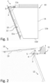
- the present invention relates to a hood 10 for extracting cooking fumes, comprising a box-shaped body 11, preferably arranged to be installed on a wall.
- the box-shaped body 11 can be recessed or partially recessed inside the wall.
- the box-shaped body 11 has a rear side 1 1b, directly facing the wall and opposite the front side 11a.
- the box-shaped body 11 has an upper side 11c, preferably facing a ceiling perpendicular to the wall on which the hood 10 is installed.
- the box-shaped body has a lower side 11d, facing a hob.
- the hood 10 comprises suction means, not illustrated, positioned internally to the box-shaped body 11 for extracting the cooking fumes through the opening 12. Still preferably, the hood 10 comprises a filter, not illustrated, positioned at the opening 12 and adapted to separate the box-shaped body 11 from an external environment on which the hood 10 faces.
- the opening 12 is inclined downwards, i.e. towards the hob, in such a way as to be turned towards the cooking fumes.
- the cover panel 13 may be semi-transparent or opaque. Still optionally, the cover panel 13 may be made of glass and/or of polymeric material and/or of metal.
- the hood 10 comprises at least one hinge 1.
- the hood 10 comprises two hinges 1 spaced apart along a horizontal direction parallel to the upper side 11c.
- the hinge 1 comprises a fixed element 2 fixed to the box-shaped body 11, shown in the attached figures 1-7 .
- the upper side 11c of the box-shaped body 11 comprises a seat 6 adapted to receive the fixed element 2, which is precisely inserted in said seat 6.
- the hinge 1 further comprises a movable element 3 rotatably connected to the fixed element 2 and fixed to the cover panel 13.
- the movable element 3 comprises a main arm 4, which has a first end 41 fixed to the cover panel 13 and a second end 42 rotatably connected to the fixed element 2 and rotatable with respect to a first rotation axis Ri.
- the rotation axis Ri is parallel to the horizontal direction.
- connection means 21 such as, by way of example only, threaded members.
- connection means 21 make it possible to disconnect the fixed element 2 of the hinge 11 from the box-shaped body 11 of the hood 10 and, consequently, the cover panel 13 from the box-shaped body 11.
- the movable element 3 further comprises an anchoring arm 5 rotatably connected to the main arm 4 and rotatable with respect to a second rotation axis R 2 , parallel to the first rotation axis Ri.
- the anchoring arm 5 has a first end 51 reversibly couplable with the fixed element 2 to lock the cover panel 13 in the open configuration.
- the anchoring arm 5 has a second free end 52, i.e. not connected to any further element of the hood 10 or of the hinge 1.
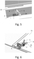
- the hinge 1 is switchable between at least two operating configurations, i.e. between a first configuration, shown in figure 3 , and a second configuration, shown in figure 4 .
- the first end 41 of the main arm 4 is positioned in front of the opening 12 of the box-shaped body 11 for positioning the cover panel 13 in the closed configuration.
- the first end 41 of the main arm 4 is raised with respect to the opening 12 for positioning the cover panel 13 in the open configuration.
- the hinge 1 is configured to switch the cover panel 13 between the closed configuration and the open configuration when the hinge 1 itself switches between the first configuration and the second configuration, respectively.
- “raised” means that the first end 41 of the main arm 4 is spaced from the opening 12 along a plane parallel to the rear side 11b of the hood 10, and faces away from the lower side 11d.
- the hinge 1 of the present invention can be switched into a plurality of intermediate configurations, comprised between the first configuration and the second configuration.
- the main arm 4 in the intermediate configurations identifies an angle with respect to the upper side 11c of the box-shaped body 11 comprised between the angle identified with respect to the upper side 11c in the first configuration and the angle identified with respect to the upper side 11c in the second configuration.
- the anchoring arm 5 is switchable between at least two operating configurations, i.e. between an unlocking configuration, visible, for example, in figures 3 and 6 , and a locking configuration, shown in figure 4 . It is worth noting that the anchoring arm 5 in the locking configuration fixes the cover panel 13 in the open configuration.
- the first end 51 of the anchoring arm 5 is movable with respect to the fixed element 2.
- the first end 51 of the anchoring arm 5 is reversibly coupled to the fixed element 2.
- anchoring arm 5 is switchable between the unlocking configuration and the locking configuration when the hinge 1 is in the second configuration.
- it is useful to lock the cover panel 13 in this configuration to prevent it from rotating again into the closed configuration due to its weight.
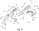
- the hinge 1 comprises first rotation members 1a adapted to connect the main arm 4 to the fixed element 2.
- the first rotation members 1a are configured to make the main arm 4 rotatable with respect to the first rotation axis R 1 in order to switch the hinge 1 between the first configuration and the second configuration.
- the first rotation members 1a comprise a first hole 22 and a first pin 44 insertable into the first hole 22.
- the first pin 44 is configured to rotate with respect to the first rotation axis Ri inside the first hole 22.
- the fixed element 2 comprises the first hole 22 while the main arm 4 comprises the first pin 44, which protrudes from the second end 42 of the main arm 4, in approach to the fixed element 2.
- the hinge 1 comprises second rotation members 1b adapted to connect the main arm 4 to the anchoring arm 5.
- the second rotation members 1b are configured to make the anchoring arm 5 rotatable with respect to the second rotation axis R 2 in order to switch the anchoring arm 5 between the unlocking configuration and the locking configuration.
- the second rotation members 1 1b comprise a second hole 53 and a second pin 43 insertable into the second hole 43.
- the second pin 43 is configured to rotate with respect to the second rotation axis R 2 inside the second hole 53.
- the anchoring arm 5 comprises the second hole 53 while the main arm 4 comprises the second pin 43, which protrudes from a central portion of the main arm 4, away from the fixed element 4.
- the second pin 43 protrudes from the main arm 4 in the opposite direction with respect to the first pin 44.
- the placement of the first hole 22 and/or of the second hole 53 can be exchanged, respectively, with that of the first pin 44 and/or of the second pin 43.
- the main arm 4 is defined by a first pair of rods 4a, 4b, wherein each rod comprises a respective end of the main arm 4.
- the anchoring arm 5 is defined by a second pair of rods 5a, 5b, wherein each rod comprises a respective end of the anchoring arm 5.
- the rod 5b of the second pair of rods which comprises the second end 52 of the anchoring arm 5, is in turn defined by a further pair of rods 5b 1 , 5b 2 .
- the fixed element 2 comprises a base 25 connectable to the box-shaped body 11, on which the first hole 22 is preferably made.
- the base 25 is parallel to the upper side 11c of the box-shaped body 11.
- the fixed element 2 comprises a coupling portion 23 and the first end 51 of the anchoring arm 5 is at least partly fixable to the coupling portion 23.
- the first end 51 of the anchoring arm 5 is at least partly counter-shaped to the coupling portion 23 and is adapted to engage said coupling portion 23.
- the coupling portion 23 has a coupling profile 24 engageable by the first end 51 of the anchoring arm 5, in detail, in the locking configuration of the anchoring arm 5.
- the coupling portion 23 protrudes from the base 25, internally to the box-shaped body 11, and defines the coupling profile 24.
- the coupling portion 23 is located between the base 25 of the fixed element 2 and the upper side 11c of the box-shaped body 11, preferably inside the seat 6.
- the first end 51 of the anchoring arm 5 is inserted internally to the seat 6, between the base 25 of the fixed element 2 and the upper side 11c of the box-shaped body 11.
- the coupling portion 23 is placed near a lateral edge 25a of the base 25 of the fixed element 2, and protrudes from the fixed element 2 away from the upper side 11c of the box-shaped body 11.
- the coupling portion 23 comprises a pair of parallel walls 23a, which are spaced from each other by the coupling profile 24 placed perpendicularly to the two walls 23a and internally to the two walls 23a.
- the first end 51 of the anchoring arm 5 has a hook shape, counter-shaped to the coupling profile 24, insertable at least in part between the two parallel walls 23a of the coupling portion 23.
- the anchoring arm 5 may comprise a gripping portion 54 positioned at the second end 52 of the anchoring arm 5, as shown in figure 5 .
- this gripping portion 54 is graspable by a user to allow gripping the anchoring arm 5 in order to uncouple the anchoring arm 5 from the fixed element 2 and, consequently, bring the anchoring arm 5 into the unlocking configuration. Still consequently, in this way it is possible to bring the cover panel 13 into the closed configuration.
- the gripping portion 54 comprises a plate parallel to the front side 11a.
Landscapes
- Engineering & Computer Science (AREA)
- Chemical & Material Sciences (AREA)
- Combustion & Propulsion (AREA)
- Mechanical Engineering (AREA)
- General Engineering & Computer Science (AREA)
- Ventilation (AREA)
- Hinges (AREA)
Applications Claiming Priority (1)
| Application Number | Priority Date | Filing Date | Title |
|---|---|---|---|
| IT102023000005673A IT202300005673A1 (it) | 2023-03-24 | 2023-03-24 | Cappa per l’aspirazione di fumi di cottura |
Publications (3)
| Publication Number | Publication Date |
|---|---|
| EP4435331A1 true EP4435331A1 (de) | 2024-09-25 |
| EP4435331B1 EP4435331B1 (de) | 2025-10-22 |
| EP4435331C0 EP4435331C0 (de) | 2025-10-22 |
Family
ID=86657495
Family Applications (1)
| Application Number | Title | Priority Date | Filing Date |
|---|---|---|---|
| EP24165027.4A Active EP4435331B1 (de) | 2023-03-24 | 2024-03-21 | Abzugshaube für kochdünsten |
Country Status (2)
| Country | Link |
|---|---|
| EP (1) | EP4435331B1 (de) |
| IT (1) | IT202300005673A1 (de) |
Citations (4)
| Publication number | Priority date | Publication date | Assignee | Title |
|---|---|---|---|---|
| CN106839045A (zh) * | 2017-04-10 | 2017-06-13 | 珠海格力电器股份有限公司 | 吸油烟机的面板开合结构及吸油烟机 |
| WO2021019397A1 (en) | 2019-08-01 | 2021-02-04 | Elica S.P.A. | Vertical hood |
| EP3922914A1 (de) * | 2020-06-09 | 2021-12-15 | ELICA S.p.A. | Dunstabzugshaube mit abdeckung |
| CN113898982A (zh) * | 2020-06-22 | 2022-01-07 | 佛山市顺德区美的洗涤电器制造有限公司 | 吸油烟机 |
-
2023
- 2023-03-24 IT IT102023000005673A patent/IT202300005673A1/it unknown
-
2024
- 2024-03-21 EP EP24165027.4A patent/EP4435331B1/de active Active
Patent Citations (4)
| Publication number | Priority date | Publication date | Assignee | Title |
|---|---|---|---|---|
| CN106839045A (zh) * | 2017-04-10 | 2017-06-13 | 珠海格力电器股份有限公司 | 吸油烟机的面板开合结构及吸油烟机 |
| WO2021019397A1 (en) | 2019-08-01 | 2021-02-04 | Elica S.P.A. | Vertical hood |
| EP3922914A1 (de) * | 2020-06-09 | 2021-12-15 | ELICA S.p.A. | Dunstabzugshaube mit abdeckung |
| CN113898982A (zh) * | 2020-06-22 | 2022-01-07 | 佛山市顺德区美的洗涤电器制造有限公司 | 吸油烟机 |
Also Published As
| Publication number | Publication date |
|---|---|
| EP4435331B1 (de) | 2025-10-22 |
| EP4435331C0 (de) | 2025-10-22 |
| IT202300005673A1 (it) | 2024-09-24 |
Similar Documents
| Publication | Publication Date | Title |
|---|---|---|
| CN107109864B (zh) | 可直接驱动可调节锁舌到碰簧销间距的互联锁 | |
| US5083822A (en) | Median housing for multipoint antipanic lock and antipanic lock fitted with such a housing | |
| KR101012498B1 (ko) | 레버의 방향전환이 가능한 슬라이딩 도어 잠금장치용 손잡이 | |
| JP2018509972A (ja) | 洗浄機 | |
| EP4007870B1 (de) | Vertikale haube | |
| EP4435331A1 (de) | Abzugshaube für kochdünsten | |
| KR102654720B1 (ko) | 자동잠금 작동 및 해제의 스위칭이 가능한 슬라이딩 창호의 핸들 조립체 | |
| KR100432810B1 (ko) | 도어 록킹장치 | |
| EP1470309B1 (de) | Gelenkkonstruktion | |
| US4059924A (en) | Operating mechanism for doors and windows | |
| KR102141548B1 (ko) | 푸쉬/풀 양방향작동이 가능한 푸쉬풀형 도어록 | |
| CA3064591C (en) | Side action flush lock for casement window and method of operating the same | |
| JP4052796B2 (ja) | 水平作動式閉鎖装置 | |
| JP4953397B2 (ja) | 車両用ドアロック装置 | |
| EP4446537A1 (de) | Scharnier für eine vertikale haube | |
| CN101255781B (zh) | 门窗结构 | |
| EP2279318B1 (de) | Nach aussen öffnende fenster- oder türanordnung | |
| JP4014798B2 (ja) | 着脱自在な開閉扉用ヒンジ | |
| JP7317508B2 (ja) | 建具 | |
| CN223286950U (zh) | 驱动组件及具有其的烹饪器具 | |
| KR200252596Y1 (ko) | 도어 록킹장치 | |
| JPH0729273U (ja) | すべり出し窓 | |
| US4713911A (en) | Auxiliary window lock | |
| KR100763452B1 (ko) | 도어 락 장치 | |
| CN113027247B (zh) | 一种门锁及家用器具 |
Legal Events
| Date | Code | Title | Description |
|---|---|---|---|
| PUAI | Public reference made under article 153(3) epc to a published international application that has entered the european phase |
Free format text: ORIGINAL CODE: 0009012 |
|
| STAA | Information on the status of an ep patent application or granted ep patent |
Free format text: STATUS: THE APPLICATION HAS BEEN PUBLISHED |
|
| AK | Designated contracting states |
Kind code of ref document: A1 Designated state(s): AL AT BE BG CH CY CZ DE DK EE ES FI FR GB GR HR HU IE IS IT LI LT LU LV MC ME MK MT NL NO PL PT RO RS SE SI SK SM TR |
|
| STAA | Information on the status of an ep patent application or granted ep patent |
Free format text: STATUS: REQUEST FOR EXAMINATION WAS MADE |
|
| 17P | Request for examination filed |
Effective date: 20250311 |
|
| GRAP | Despatch of communication of intention to grant a patent |
Free format text: ORIGINAL CODE: EPIDOSNIGR1 |
|
| STAA | Information on the status of an ep patent application or granted ep patent |
Free format text: STATUS: GRANT OF PATENT IS INTENDED |
|
| RIC1 | Information provided on ipc code assigned before grant |
Ipc: E05C 17/50 20060101ALI20250501BHEP Ipc: E05C 17/00 20060101ALI20250501BHEP Ipc: F24C 15/20 20060101AFI20250501BHEP |
|
| INTG | Intention to grant announced |
Effective date: 20250523 |
|
| GRAS | Grant fee paid |
Free format text: ORIGINAL CODE: EPIDOSNIGR3 |
|
| GRAA | (expected) grant |
Free format text: ORIGINAL CODE: 0009210 |
|
| STAA | Information on the status of an ep patent application or granted ep patent |
Free format text: STATUS: THE PATENT HAS BEEN GRANTED |
|
| AK | Designated contracting states |
Kind code of ref document: B1 Designated state(s): AL AT BE BG CH CY CZ DE DK EE ES FI FR GB GR HR HU IE IS IT LI LT LU LV MC ME MK MT NL NO PL PT RO RS SE SI SK SM TR |
|
| REG | Reference to a national code |
Ref country code: CH Ref legal event code: F10 Free format text: ST27 STATUS EVENT CODE: U-0-0-F10-F00 (AS PROVIDED BY THE NATIONAL OFFICE) Effective date: 20251022 Ref country code: GB Ref legal event code: FG4D |
|
| REG | Reference to a national code |
Ref country code: DE Ref legal event code: R096 Ref document number: 602024000988 Country of ref document: DE |
|
| REG | Reference to a national code |
Ref country code: IE Ref legal event code: FG4D |
|
| U01 | Request for unitary effect filed |
Effective date: 20251120 |
|
| U07 | Unitary effect registered |
Designated state(s): AT BE BG DE DK EE FI FR IT LT LU LV MT NL PT RO SE SI Effective date: 20251127 |