EP4435286A1 - Bremsvorrichtung mit verstellbarer parallelität für bremsbeläge - Google Patents
Bremsvorrichtung mit verstellbarer parallelität für bremsbeläge Download PDFInfo
- Publication number
- EP4435286A1 EP4435286A1 EP23204076.6A EP23204076A EP4435286A1 EP 4435286 A1 EP4435286 A1 EP 4435286A1 EP 23204076 A EP23204076 A EP 23204076A EP 4435286 A1 EP4435286 A1 EP 4435286A1
- Authority
- EP
- European Patent Office
- Prior art keywords
- adjustable
- main body
- friction pad
- flat
- driving disc
- Prior art date
- Legal status (The legal status is an assumption and is not a legal conclusion. Google has not performed a legal analysis and makes no representation as to the accuracy of the status listed.)
- Withdrawn
Links
Images
Classifications
-
- F—MECHANICAL ENGINEERING; LIGHTING; HEATING; WEAPONS; BLASTING
- F16—ENGINEERING ELEMENTS AND UNITS; GENERAL MEASURES FOR PRODUCING AND MAINTAINING EFFECTIVE FUNCTIONING OF MACHINES OR INSTALLATIONS; THERMAL INSULATION IN GENERAL
- F16D—COUPLINGS FOR TRANSMITTING ROTATION; CLUTCHES; BRAKES
- F16D65/00—Parts or details
- F16D65/14—Actuating mechanisms for brakes; Means for initiating operation at a predetermined position
- F16D65/16—Actuating mechanisms for brakes; Means for initiating operation at a predetermined position arranged in or on the brake
- F16D65/18—Actuating mechanisms for brakes; Means for initiating operation at a predetermined position arranged in or on the brake adapted for drawing members together, e.g. for disc brakes
-
- F—MECHANICAL ENGINEERING; LIGHTING; HEATING; WEAPONS; BLASTING
- F16—ENGINEERING ELEMENTS AND UNITS; GENERAL MEASURES FOR PRODUCING AND MAINTAINING EFFECTIVE FUNCTIONING OF MACHINES OR INSTALLATIONS; THERMAL INSULATION IN GENERAL
- F16D—COUPLINGS FOR TRANSMITTING ROTATION; CLUTCHES; BRAKES
- F16D65/00—Parts or details
- F16D65/38—Slack adjusters
- F16D65/40—Slack adjusters mechanical
- F16D65/42—Slack adjusters mechanical non-automatic
- F16D65/46—Slack adjusters mechanical non-automatic with screw-thread and nut
-
- B—PERFORMING OPERATIONS; TRANSPORTING
- B62—LAND VEHICLES FOR TRAVELLING OTHERWISE THAN ON RAILS
- B62K—CYCLES; CYCLE FRAMES; CYCLE STEERING DEVICES; RIDER-OPERATED TERMINAL CONTROLS SPECIALLY ADAPTED FOR CYCLES; CYCLE AXLE SUSPENSIONS; CYCLE SIDE-CARS, FORECARS, OR THE LIKE
- B62K23/00—Rider-operated controls specially adapted for cycles, i.e. means for initiating control operations, e.g. levers, grips
- B62K23/02—Rider-operated controls specially adapted for cycles, i.e. means for initiating control operations, e.g. levers, grips hand actuated
- B62K23/06—Levers
-
- B—PERFORMING OPERATIONS; TRANSPORTING
- B62—LAND VEHICLES FOR TRAVELLING OTHERWISE THAN ON RAILS
- B62L—BRAKES SPECIALLY ADAPTED FOR CYCLES
- B62L3/00—Brake-actuating mechanisms; Arrangements thereof
- B62L3/02—Brake-actuating mechanisms; Arrangements thereof for control by a hand lever
- B62L3/023—Brake-actuating mechanisms; Arrangements thereof for control by a hand lever acting on fluid pressure systems
-
- F—MECHANICAL ENGINEERING; LIGHTING; HEATING; WEAPONS; BLASTING
- F16—ENGINEERING ELEMENTS AND UNITS; GENERAL MEASURES FOR PRODUCING AND MAINTAINING EFFECTIVE FUNCTIONING OF MACHINES OR INSTALLATIONS; THERMAL INSULATION IN GENERAL
- F16D—COUPLINGS FOR TRANSMITTING ROTATION; CLUTCHES; BRAKES
- F16D55/00—Brakes with substantially-radial braking surfaces pressed together in axial direction, e.g. disc brakes
- F16D55/02—Brakes with substantially-radial braking surfaces pressed together in axial direction, e.g. disc brakes with axially-movable discs or pads pressed against axially-located rotating members
- F16D55/22—Brakes with substantially-radial braking surfaces pressed together in axial direction, e.g. disc brakes with axially-movable discs or pads pressed against axially-located rotating members by clamping an axially-located rotating disc between movable braking members, e.g. movable brake discs or brake pads
- F16D55/224—Brakes with substantially-radial braking surfaces pressed together in axial direction, e.g. disc brakes with axially-movable discs or pads pressed against axially-located rotating members by clamping an axially-located rotating disc between movable braking members, e.g. movable brake discs or brake pads with a common actuating member for the braking members
- F16D55/225—Brakes with substantially-radial braking surfaces pressed together in axial direction, e.g. disc brakes with axially-movable discs or pads pressed against axially-located rotating members by clamping an axially-located rotating disc between movable braking members, e.g. movable brake discs or brake pads with a common actuating member for the braking members the braking members being brake pads
- F16D55/2255—Brakes with substantially-radial braking surfaces pressed together in axial direction, e.g. disc brakes with axially-movable discs or pads pressed against axially-located rotating members by clamping an axially-located rotating disc between movable braking members, e.g. movable brake discs or brake pads with a common actuating member for the braking members the braking members being brake pads in which the common actuating member is pivoted
-
- F—MECHANICAL ENGINEERING; LIGHTING; HEATING; WEAPONS; BLASTING
- F16—ENGINEERING ELEMENTS AND UNITS; GENERAL MEASURES FOR PRODUCING AND MAINTAINING EFFECTIVE FUNCTIONING OF MACHINES OR INSTALLATIONS; THERMAL INSULATION IN GENERAL
- F16D—COUPLINGS FOR TRANSMITTING ROTATION; CLUTCHES; BRAKES
- F16D65/00—Parts or details
- F16D65/02—Braking members; Mounting thereof
- F16D65/04—Bands, shoes or pads; Pivots or supporting members therefor
- F16D65/092—Bands, shoes or pads; Pivots or supporting members therefor for axially-engaging brakes, e.g. disc brakes
-
- B—PERFORMING OPERATIONS; TRANSPORTING
- B62—LAND VEHICLES FOR TRAVELLING OTHERWISE THAN ON RAILS
- B62L—BRAKES SPECIALLY ADAPTED FOR CYCLES
- B62L1/00—Brakes; Arrangements thereof
- B62L1/005—Brakes; Arrangements thereof constructional features of brake elements, e.g. fastening of brake blocks in their holders
-
- F—MECHANICAL ENGINEERING; LIGHTING; HEATING; WEAPONS; BLASTING
- F16—ENGINEERING ELEMENTS AND UNITS; GENERAL MEASURES FOR PRODUCING AND MAINTAINING EFFECTIVE FUNCTIONING OF MACHINES OR INSTALLATIONS; THERMAL INSULATION IN GENERAL
- F16D—COUPLINGS FOR TRANSMITTING ROTATION; CLUTCHES; BRAKES
- F16D55/00—Brakes with substantially-radial braking surfaces pressed together in axial direction, e.g. disc brakes
- F16D2055/0004—Parts or details of disc brakes
- F16D2055/007—Pins holding the braking members
-
- F—MECHANICAL ENGINEERING; LIGHTING; HEATING; WEAPONS; BLASTING
- F16—ENGINEERING ELEMENTS AND UNITS; GENERAL MEASURES FOR PRODUCING AND MAINTAINING EFFECTIVE FUNCTIONING OF MACHINES OR INSTALLATIONS; THERMAL INSULATION IN GENERAL
- F16D—COUPLINGS FOR TRANSMITTING ROTATION; CLUTCHES; BRAKES
- F16D2121/00—Type of actuator operation force
- F16D2121/14—Mechanical
-
- F—MECHANICAL ENGINEERING; LIGHTING; HEATING; WEAPONS; BLASTING
- F16—ENGINEERING ELEMENTS AND UNITS; GENERAL MEASURES FOR PRODUCING AND MAINTAINING EFFECTIVE FUNCTIONING OF MACHINES OR INSTALLATIONS; THERMAL INSULATION IN GENERAL
- F16D—COUPLINGS FOR TRANSMITTING ROTATION; CLUTCHES; BRAKES
- F16D2127/00—Auxiliary mechanisms
- F16D2127/02—Release mechanisms
Definitions
- the present invention relates to a brake device, and more particularly, to an adjustable parallelism brake device for brake pads.
- Bicycles and electric power-assisted bicycles are increasingly becoming exercise tools for cycling enthusiasts.
- Braking devices are frequently used in their operation.
- Conventional mechanical disc brake devices often experience the issue of the brake pads pressing unevenly against the friction surface, causing deformation of the backing plate of the brake pad due to prolonged use. This results in reduced pressure, leading to a decrease in braking force and friction.
- the deformation of the brake pads becomes particularly noticeable after extended periods of use.
- the present invention is to provide an adjustable parallelism brake device for brake pads. This is achieved through the use of adjustable screws and flat bolts to adjust the angles of the brake pads and the clamping angle between the two brake pads.
- the present invention relates to an adjustable parallelism brake device for brake pads, and comprises a pivotal arm, a main body connected to the pivotal arm, a driving disc, and an attached body.
- the main body is fixedly connected to the attached body by multiple connecting screws.
- the pivotal arm is connected between the main body and the driving disc.
- the pivotal arm is connected to a cable.
- the driving disc has a flat bearing and a flat washer mounted thereto. The driving disc contacts against the main body through the flat washer and the flat bearing.
- a directional drive disc is located below the driving disc.
- Multiple adjustable screws threadedly extend through threaded holes on both sides of the directional drive disc, and each adjustable screw has a head which supports a first friction pad by a first V-shaped spring.
- the attached body includes multiple flat threaded columns, and each flat threaded column includes a distal end which supports a second friction pad by a second V-shaped spring.
- the first friction pad and the second friction pad each have a hole defined in one side thereof.
- a pin passes through the hole of each of the first and second friction pads and is secured to the attached body.
- the directional drive disc includes at least two holes to which the adjustable screws are connected.
- each of the adjustable screws has a compression spring mounted thereto which is located corresponding to a hole in the main body.
- a washer and a locking ring are respectively mounted to each of the adjustable screws.
- the compression spring on each adjustable screw contacts the washer corresponding thereto.
- the adjustable screws extend into the main body and each include a hexagonal recess defined in the head thereof.
- each of the driving disc and the directional drive disc has multiple grooves defined in a facing end surface thereof.
- Each groove is an arc-teardrop shaped groove with varying depths.
- the grooves of the driving disc and the directional drive disc are in pairs.
- a ball is movably accommodated in each pair of the grooves of the driving disc and the directional drive disc.
- the flat threaded columns are threadedly connected to the inside the attached body, and the distal end of each of the flat threaded columns supports the second friction pad by the V-shaped spring.
- the first V-shaped spring provides an expansive force to bias the head of the adjustable screws to contact the first pad.
- the second V-shaped spring provides another expansive force to bias the distal ends of the flat threaded columns to contact the second friction pad.
- the pins are open-ended pins which are inserted into holes in both first friction pad and the second friction pad.
- the main body has a guide member for passage of the cable.
- the present invention includes the following advantages.
- the two adjustable screws on the main body can be adjusted by using a wrench to modify their positions. This facilitates the adjustment of the distance between the friction pads and allows to adjust the gaps between two ends of the friction pads and the brake disc. This ensures the friction pads and brake disc are perfectly parallel.
- the two flat threaded columns on the attached body can also be adjusted to change the gaps between the two ends of the corresponding friction pads and the brake disc. This ensures that the friction pads and brake disc remain consistently parallel. This increases the contact surface during braking, reduces the gap between the friction pads and the brake disc, thereby obtaining stronger braking effectiveness and improved braking feel. Additionally, it prevents deformation of the friction pads due to prolonged pressure on their center.
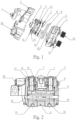
- the adjustable parallelism brake device for brake pads of the present invention comprises a pivotal arm 1, a main body 2 connected to the pivotal arm 1, a driving disc 3, and an attached body 4.
- the main body 2 is fixedly connected to the attached body 4 through multiple connecting screws 9.
- the pivotal arm 1 has one of two ends thereof connected to the main body 2 via screws and a cable is connected to the pivotal arm 1.
- Another one of the two ends of the pivotal arm 1 is fixedly connected to the driving disc 3 via screws.
- the driving disc 3 has a flat bearing 17 and a flat washer 5 mounted thereto. The driving disc 3 contacts against the main body 2 through the flat washer 5 and the flat bearing 17.
- a directional drive disc 6 is located below the driving disc 3.
- each adjustable screw 7 threadedly extend through threaded holes on both sides of the directional drive disc 6, and each adjustable screw 7 has a head which supports a first friction pad 8 by a first V-shaped spring 10.
- the attached body 4 includes multiple flat threaded columns 16, and the distal end of each flat threaded column 16 supports a second friction pad 11 by a second V-shaped spring 100.
- the first friction pad 8 and the second friction pad 11 each have a hole defined in one side thereof, and a pin 12 passes through the hole of each of the first and second friction pads 8, 11, and is secured to the attached body 4.
- the pins 12 are open-ended pins.
- the cable that is connected to the pivotal arm 1 is then connected to the brake lever (not shown).
- the cable pivots the pivotal lever 1 which rotates the driving disc 3.
- Each of the driving disc 3 and the directional drive disc 6 has multiple grooves 18 defined in their facing end surface.
- the grooves 18 of the driving disc 3 and the directional drive disc 6 are in pairs.
- a ball 19 is movably accommodated in each pair of the grooves 18 of the driving disc 3 and the directional drive disc 6.
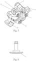
- the directional drive disc 6 has threaded holes throughout which the adjustable screws 7 threadedly extend. Therefore, the rotation of the directional drive disc 6 causes the balls 9 to move in the grooves 18.
- Each groove 18 is an arc-teardrop shaped groove with varying depths, so that when the balls 19 moves from the deep area to the shallow area of the grooves 18, the gap between the driving disc 3 and the directional drive disc 6 is increased.
- the directional drive disc 6 and the adjustable screws 7 then move downward. Because each adjustable screw 7 has the first V-shaped spring 10 to support the first friction pad 8, so that the first friction pad 8 performs a braking action.
- each flat threaded column 16 has the second V-shaped spring 100 to support the second friction pad 11, so that the flat threaded columns 16 adjust the position of the second friction pad 11, and the adjustable screws 7 adjust the position of the first friction pad 8.
- the distance between the first and second friction pads 8, 11 can be adjusted according to practical needs such as the braking distance and force.
- the directional drive disc 6 includes at least two holes to which the adjustable screws 7 are threadedly connected to ensure the movement stability of the directional drive disc 6.
- each of the adjustable screws 7 has a compression spring 13 mounted thereto which is located corresponding to a hole in the main body 2.
- a washer 14 and a locking ring 15 are respectively mounted to each of the adjustable screws 7.
- the compression spring 13 on each adjustable screw 7 contacts the washer 14 corresponding thereto.
- the adjustable screws 7 extend into the main body 2, and each adjustable screw 7 includes a hexagonal recess defined in the head thereof.
- the top of the compression spring 13 is in contact with the washer 14.
- pressure is applied to the compression spring 13, and releasing the lever 1 causes the compression spring 13 to restore the adjustable screw 7 to its initial position.
- the head of the adjustable screw 7 is designed with the hexagonal slot mentioned above, allowing for adjustment BY using a hex wrench to modify the height position of the adjustable screw 7 during adjustments.
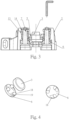
- the flat threaded columns 16 are threadedly connected to the inside of the attached body 4, and the distal end of each of the flat threaded columns 16 supports the second friction pad 11 by the second V-shaped spring 100.
- the flat threaded column 16 is threaded inside the attached body 4.
- the end of the flat threaded column 16 has a magnet to mount the second friction pad 11.
- the flat threaded column 16 can be rotated by using a wrench to adjust its position, allowing for the adjustment of the position of the second friction pad 11. This enables the adjustment of the gap and parallelism between the first friction pad 8 and the second friction pad 11. This adjustment can be made based on the force applied to the brake lever or the tension of the cable when manually operated.
- the first V-shaped spring 10 provides an expansive force to bias the head of the adjustable screws 7 to contact the first pad 8.
- the second V-shaped spring 100 provides another expansive force to bias the distal ends of the flat threaded columns 16 to contact the second friction pad 11.
- the pins 12 are open-ended pins which are inserted into holes in both first friction pad 8 and the second friction pad 11.
- the first friction pad 8 and the second friction pad 11 move along the pin 12.
- the pin 12 is connected to the attached body 4, serving for the installation and positioning of the first friction pad 8 and the second friction pad 11.
- the main body 2 and the attached body 4 are securely connected through connecting screws 9 to ensure the stability and integrity of the entire brake device.
- the main body 2 has a guide member 20 so that the cable passes through the guide member 20 and is connected to the pivotal arm 1.
Landscapes
- Engineering & Computer Science (AREA)
- General Engineering & Computer Science (AREA)
- Mechanical Engineering (AREA)
- Physics & Mathematics (AREA)
- Fluid Mechanics (AREA)
- Braking Arrangements (AREA)
- Transmission Of Braking Force In Braking Systems (AREA)
Applications Claiming Priority (1)
| Application Number | Priority Date | Filing Date | Title |
|---|---|---|---|
| TW112202584U TWM650641U (zh) | 2023-03-22 | 2023-03-22 | 一種摩擦塊平行度可調的制動組件 |
Publications (1)
| Publication Number | Publication Date |
|---|---|
| EP4435286A1 true EP4435286A1 (de) | 2024-09-25 |
Family
ID=90456094
Family Applications (2)
| Application Number | Title | Priority Date | Filing Date |
|---|---|---|---|
| EP23204076.6A Withdrawn EP4435286A1 (de) | 2023-03-22 | 2023-10-17 | Bremsvorrichtung mit verstellbarer parallelität für bremsbeläge |
| EP23204085.7A Pending EP4434867A1 (de) | 2023-03-22 | 2023-10-17 | Bremsanlage mit geschlossenem hydraulikzylinder |
Family Applications After (1)
| Application Number | Title | Priority Date | Filing Date |
|---|---|---|---|
| EP23204085.7A Pending EP4434867A1 (de) | 2023-03-22 | 2023-10-17 | Bremsanlage mit geschlossenem hydraulikzylinder |
Country Status (3)
| Country | Link |
|---|---|
| US (1) | US20240318699A1 (de) |
| EP (2) | EP4435286A1 (de) |
| TW (1) | TWM650641U (de) |
Citations (3)
| Publication number | Priority date | Publication date | Assignee | Title |
|---|---|---|---|---|
| GB840392A (en) * | 1956-06-21 | 1960-07-06 | Bendix Aviat Corp | Improvements in disc brakes |
| CN113464591A (zh) * | 2021-07-27 | 2021-10-01 | 兰溪市捷克运动器材制造有限公司 | 一种刹车片平行度可调的机械碟刹 |
| CN216045128U (zh) * | 2021-07-27 | 2022-03-15 | 兰溪市捷克运动器材制造有限公司 | 一种刹车片平行度可调的机械碟刹 |
Family Cites Families (18)
| Publication number | Priority date | Publication date | Assignee | Title |
|---|---|---|---|---|
| DE1600120B2 (de) * | 1966-04-05 | 1972-03-02 | Alfred Teves Gmbh, 6000 Frankfurt | Federnde halte und rueckstellvorrichtung fuer die brems backen einer teilbelagscheibenbremse |
| FR2041002A1 (de) * | 1969-04-22 | 1971-01-29 | Dba | |
| US3670853A (en) * | 1971-01-26 | 1972-06-20 | Gen Motors Corp | Disc brake with parking brake |
| CA2001267A1 (en) * | 1988-10-24 | 1990-04-24 | Anthony C. Evans | Automatic disc brake |
| JP2873772B2 (ja) * | 1993-08-09 | 1999-03-24 | トキコ株式会社 | ディスクブレーキ |
| DE4334914A1 (de) * | 1993-10-13 | 1995-04-20 | Knorr Bremse Systeme | Druckluftbetätigte Scheibenbremse |
| ITFI20030242A1 (it) * | 2003-09-15 | 2005-03-16 | Formula Srl | Dispositivo per il comando di freni idraulici in cicli, |
| US7516616B2 (en) * | 2006-06-09 | 2009-04-14 | Shimano Inc. | Bicycle hydraulic brake actuation device |
| CN201818678U (zh) * | 2010-08-05 | 2011-05-04 | 利奇机械工业股份有限公司 | 机械式碟刹卡钳 |
| DE102012006097A1 (de) * | 2012-03-26 | 2013-09-26 | Knorr-Bremse Systeme für Nutzfahrzeuge GmbH | Zuspannvorrichtung für eine drehhebelbetätigte Scheibenbremse |
| DE102012108676B3 (de) * | 2012-09-17 | 2014-02-06 | Knorr-Bremse Systeme für Nutzfahrzeuge GmbH | Scheibenbremse mit einer Verschleißnachstellvorrichtung |
| DE102012108672B3 (de) * | 2012-09-17 | 2014-02-06 | Knorr-Bremse Systeme für Nutzfahrzeuge GmbH | Nachstelleinrichtung einer Scheibenbremse, eine entsprechende Scheibenbremse und Verfahren zum Betreiben einer Verschleißnachstellvorrichtung einer Scheibenbremse |
| TW201418595A (zh) * | 2012-11-14 | 2014-05-16 | Sirius Disc Brake Technology Ltd | 機械式碟煞機構 |
| TWM463230U (zh) * | 2013-02-08 | 2013-10-11 | Tektro Technology Corp | 自行車碟刹結構 |
| US9168974B2 (en) * | 2013-04-12 | 2015-10-27 | Jonathan K. Harris | Cable-actuated disc brake for a bicycle |
| US9290232B2 (en) * | 2014-03-24 | 2016-03-22 | Sram, Llc | Variable rate assembly for a brake system for bicycle |
| US11221027B2 (en) * | 2020-05-19 | 2022-01-11 | Shimano Inc. | Hydraulic device |
| TWI814125B (zh) * | 2021-11-03 | 2023-09-01 | 阿米瑟工業股份有限公司 | 自行車剎車裝置 |
-
2023
- 2023-03-22 TW TW112202584U patent/TWM650641U/zh unknown
- 2023-09-29 US US18/477,925 patent/US20240318699A1/en active Pending
- 2023-10-17 EP EP23204076.6A patent/EP4435286A1/de not_active Withdrawn
- 2023-10-17 EP EP23204085.7A patent/EP4434867A1/de active Pending
Patent Citations (3)
| Publication number | Priority date | Publication date | Assignee | Title |
|---|---|---|---|---|
| GB840392A (en) * | 1956-06-21 | 1960-07-06 | Bendix Aviat Corp | Improvements in disc brakes |
| CN113464591A (zh) * | 2021-07-27 | 2021-10-01 | 兰溪市捷克运动器材制造有限公司 | 一种刹车片平行度可调的机械碟刹 |
| CN216045128U (zh) * | 2021-07-27 | 2022-03-15 | 兰溪市捷克运动器材制造有限公司 | 一种刹车片平行度可调的机械碟刹 |
Also Published As
| Publication number | Publication date |
|---|---|
| US20240318699A1 (en) | 2024-09-26 |
| EP4434867A1 (de) | 2024-09-25 |
| TWM650641U (zh) | 2024-01-21 |
Similar Documents
| Publication | Publication Date | Title |
|---|---|---|
| KR100463860B1 (ko) | 바이스의 파악력 설정장치 | |
| CN106659050A (zh) | 楔形锁紧装置及使用该锁紧装置的电气模块组件、机柜 | |
| US10119584B2 (en) | Disk brake device with disk pad guiding structure | |
| EP4435286A1 (de) | Bremsvorrichtung mit verstellbarer parallelität für bremsbeläge | |
| JP2006052035A (ja) | エレベーター用巻上機の制動装置 | |
| CN216045128U (zh) | 一种刹车片平行度可调的机械碟刹 | |
| KR200469416Y1 (ko) | 바이스 압력 증강장치 | |
| US9771125B1 (en) | Dual actuated mechanical disk brake device | |
| CN210476676U (zh) | 一种鼓式刹车片粘接夹具 | |
| CN113464591A (zh) | 一种刹车片平行度可调的机械碟刹 | |
| GB2583179A (en) | Ball clamping mechanism and bicycle carrier including the same | |
| JP4260077B2 (ja) | クランプ機構 | |
| JP7576328B2 (ja) | プレスブレーキのダイホルダー | |
| CN223136782U (zh) | 一种制动器调节器 | |
| CN209364381U (zh) | 磨床夹具 | |
| JPH05192872A (ja) | 緊定駆動装置 | |
| CN113911247B (zh) | 碟刹器、碟刹机构及自行车 | |
| CN219263044U (zh) | 一种可调节刹车片间隙的双驱动碟刹装置 | |
| US7334507B2 (en) | Teethless adjustable spanner | |
| CN2425843Y (zh) | 自行车碟式刹车的刹车片自动定位夹持装置 | |
| CN221145898U (zh) | 一种应用于公路养护作业区的监控设备 | |
| CN212022884U (zh) | 单动机械碟刹改良结构 | |
| CN223691684U (zh) | 一种用于测试工件受压面不平行的测试设备 | |
| JP4321866B2 (ja) | 雲台 | |
| CN213226495U (zh) | 一种保护膜去料带装置 |
Legal Events
| Date | Code | Title | Description |
|---|---|---|---|
| PUAI | Public reference made under article 153(3) epc to a published international application that has entered the european phase |
Free format text: ORIGINAL CODE: 0009012 |
|
| STAA | Information on the status of an ep patent application or granted ep patent |
Free format text: STATUS: THE APPLICATION HAS BEEN PUBLISHED |
|
| AK | Designated contracting states |
Kind code of ref document: A1 Designated state(s): AL AT BE BG CH CY CZ DE DK EE ES FI FR GB GR HR HU IE IS IT LI LT LU LV MC ME MK MT NL NO PL PT RO RS SE SI SK SM TR |
|
| STAA | Information on the status of an ep patent application or granted ep patent |
Free format text: STATUS: THE APPLICATION IS DEEMED TO BE WITHDRAWN |
|
| 18D | Application deemed to be withdrawn |
Effective date: 20250326 |