EP4434871A1 - Schwimmkörper und verfahren zum abführen von inertgas aus einem schwimmkörper - Google Patents
Schwimmkörper und verfahren zum abführen von inertgas aus einem schwimmkörper Download PDFInfo
- Publication number
- EP4434871A1 EP4434871A1 EP22910749.5A EP22910749A EP4434871A1 EP 4434871 A1 EP4434871 A1 EP 4434871A1 EP 22910749 A EP22910749 A EP 22910749A EP 4434871 A1 EP4434871 A1 EP 4434871A1
- Authority
- EP
- European Patent Office
- Prior art keywords
- ammonia
- mixed gas
- inert gas
- tank
- gas
- Prior art date
- Legal status (The legal status is an assumption and is not a legal conclusion. Google has not performed a legal analysis and makes no representation as to the accuracy of the status listed.)
- Pending
Links
Images


Classifications
-
- B—PERFORMING OPERATIONS; TRANSPORTING
- B63—SHIPS OR OTHER WATERBORNE VESSELS; RELATED EQUIPMENT
- B63B—SHIPS OR OTHER WATERBORNE VESSELS; EQUIPMENT FOR SHIPPING
- B63B25/00—Load-accommodating arrangements, e.g. stowing, trimming; Vessels characterised thereby
- B63B25/02—Load-accommodating arrangements, e.g. stowing, trimming; Vessels characterised thereby for bulk goods
- B63B25/08—Load-accommodating arrangements, e.g. stowing, trimming; Vessels characterised thereby for bulk goods fluid
- B63B25/12—Load-accommodating arrangements, e.g. stowing, trimming; Vessels characterised thereby for bulk goods fluid closed
- B63B25/16—Load-accommodating arrangements, e.g. stowing, trimming; Vessels characterised thereby for bulk goods fluid closed heat-insulated
-
- B—PERFORMING OPERATIONS; TRANSPORTING
- B01—PHYSICAL OR CHEMICAL PROCESSES OR APPARATUS IN GENERAL
- B01D—SEPARATION
- B01D53/00—Separation of gases or vapours; Recovering vapours of volatile solvents from gases; Chemical or biological purification of waste gases, e.g. engine exhaust gases, smoke, fumes, flue gases, aerosols
- B01D53/002—Separation of gases or vapours; Recovering vapours of volatile solvents from gases; Chemical or biological purification of waste gases, e.g. engine exhaust gases, smoke, fumes, flue gases, aerosols by condensation
-
- B—PERFORMING OPERATIONS; TRANSPORTING
- B63—SHIPS OR OTHER WATERBORNE VESSELS; RELATED EQUIPMENT
- B63J—AUXILIARIES ON VESSELS
- B63J2/00—Arrangements of ventilation, heating, cooling, or air-conditioning
- B63J2/12—Heating; Cooling
- B63J2/14—Heating; Cooling of liquid-freight-carrying tanks
-
- F—MECHANICAL ENGINEERING; LIGHTING; HEATING; WEAPONS; BLASTING
- F17—STORING OR DISTRIBUTING GASES OR LIQUIDS
- F17C—VESSELS FOR CONTAINING OR STORING COMPRESSED, LIQUEFIED OR SOLIDIFIED GASES; FIXED-CAPACITY GAS-HOLDERS; FILLING VESSELS WITH, OR DISCHARGING FROM VESSELS, COMPRESSED, LIQUEFIED, OR SOLIDIFIED GASES
- F17C13/00—Details of vessels or of the filling or discharging of vessels
- F17C13/004—Details of vessels or of the filling or discharging of vessels for large storage vessels not under pressure
-
- F—MECHANICAL ENGINEERING; LIGHTING; HEATING; WEAPONS; BLASTING
- F17—STORING OR DISTRIBUTING GASES OR LIQUIDS
- F17C—VESSELS FOR CONTAINING OR STORING COMPRESSED, LIQUEFIED OR SOLIDIFIED GASES; FIXED-CAPACITY GAS-HOLDERS; FILLING VESSELS WITH, OR DISCHARGING FROM VESSELS, COMPRESSED, LIQUEFIED, OR SOLIDIFIED GASES
- F17C13/00—Details of vessels or of the filling or discharging of vessels
- F17C13/005—Details of vessels or of the filling or discharging of vessels for medium-size and small storage vessels not under pressure
-
- F—MECHANICAL ENGINEERING; LIGHTING; HEATING; WEAPONS; BLASTING
- F17—STORING OR DISTRIBUTING GASES OR LIQUIDS
- F17C—VESSELS FOR CONTAINING OR STORING COMPRESSED, LIQUEFIED OR SOLIDIFIED GASES; FIXED-CAPACITY GAS-HOLDERS; FILLING VESSELS WITH, OR DISCHARGING FROM VESSELS, COMPRESSED, LIQUEFIED, OR SOLIDIFIED GASES
- F17C13/00—Details of vessels or of the filling or discharging of vessels
- F17C13/02—Special adaptations of indicating, measuring, or monitoring equipment
- F17C13/025—Special adaptations of indicating, measuring, or monitoring equipment having the pressure as the parameter
-
- F—MECHANICAL ENGINEERING; LIGHTING; HEATING; WEAPONS; BLASTING
- F17—STORING OR DISTRIBUTING GASES OR LIQUIDS
- F17C—VESSELS FOR CONTAINING OR STORING COMPRESSED, LIQUEFIED OR SOLIDIFIED GASES; FIXED-CAPACITY GAS-HOLDERS; FILLING VESSELS WITH, OR DISCHARGING FROM VESSELS, COMPRESSED, LIQUEFIED, OR SOLIDIFIED GASES
- F17C13/00—Details of vessels or of the filling or discharging of vessels
- F17C13/04—Arrangement or mounting of valves
-
- F—MECHANICAL ENGINEERING; LIGHTING; HEATING; WEAPONS; BLASTING
- F17—STORING OR DISTRIBUTING GASES OR LIQUIDS
- F17C—VESSELS FOR CONTAINING OR STORING COMPRESSED, LIQUEFIED OR SOLIDIFIED GASES; FIXED-CAPACITY GAS-HOLDERS; FILLING VESSELS WITH, OR DISCHARGING FROM VESSELS, COMPRESSED, LIQUEFIED, OR SOLIDIFIED GASES
- F17C9/00—Methods or apparatus for discharging liquefied or solidified gases from vessels not under pressure
-
- B—PERFORMING OPERATIONS; TRANSPORTING
- B01—PHYSICAL OR CHEMICAL PROCESSES OR APPARATUS IN GENERAL
- B01D—SEPARATION
- B01D2257/00—Components to be removed
- B01D2257/40—Nitrogen compounds
- B01D2257/406—Ammonia
-
- B—PERFORMING OPERATIONS; TRANSPORTING
- B01—PHYSICAL OR CHEMICAL PROCESSES OR APPARATUS IN GENERAL
- B01D—SEPARATION
- B01D2259/00—Type of treatment
- B01D2259/45—Gas separation or purification devices adapted for specific applications
- B01D2259/4525—Gas separation or purification devices adapted for specific applications for storage and dispensing systems
-
- B—PERFORMING OPERATIONS; TRANSPORTING
- B63—SHIPS OR OTHER WATERBORNE VESSELS; RELATED EQUIPMENT
- B63B—SHIPS OR OTHER WATERBORNE VESSELS; EQUIPMENT FOR SHIPPING
- B63B17/00—Vessels parts, details, or accessories, not otherwise provided for
- B63B17/0027—Tanks for fuel or the like ; Accessories therefor, e.g. tank filler caps
-
- F—MECHANICAL ENGINEERING; LIGHTING; HEATING; WEAPONS; BLASTING
- F17—STORING OR DISTRIBUTING GASES OR LIQUIDS
- F17C—VESSELS FOR CONTAINING OR STORING COMPRESSED, LIQUEFIED OR SOLIDIFIED GASES; FIXED-CAPACITY GAS-HOLDERS; FILLING VESSELS WITH, OR DISCHARGING FROM VESSELS, COMPRESSED, LIQUEFIED, OR SOLIDIFIED GASES
- F17C2205/00—Vessel construction, in particular mounting arrangements, attachments or identifications means
- F17C2205/03—Fluid connections, filters, valves, closure means or other attachments
- F17C2205/0302—Fittings, valves, filters, or components in connection with the gas storage device
- F17C2205/0323—Valves
- F17C2205/0332—Safety valves or pressure relief valves
-
- F—MECHANICAL ENGINEERING; LIGHTING; HEATING; WEAPONS; BLASTING
- F17—STORING OR DISTRIBUTING GASES OR LIQUIDS
- F17C—VESSELS FOR CONTAINING OR STORING COMPRESSED, LIQUEFIED OR SOLIDIFIED GASES; FIXED-CAPACITY GAS-HOLDERS; FILLING VESSELS WITH, OR DISCHARGING FROM VESSELS, COMPRESSED, LIQUEFIED, OR SOLIDIFIED GASES
- F17C2205/00—Vessel construction, in particular mounting arrangements, attachments or identifications means
- F17C2205/03—Fluid connections, filters, valves, closure means or other attachments
- F17C2205/0302—Fittings, valves, filters, or components in connection with the gas storage device
- F17C2205/0341—Filters
-
- F—MECHANICAL ENGINEERING; LIGHTING; HEATING; WEAPONS; BLASTING
- F17—STORING OR DISTRIBUTING GASES OR LIQUIDS
- F17C—VESSELS FOR CONTAINING OR STORING COMPRESSED, LIQUEFIED OR SOLIDIFIED GASES; FIXED-CAPACITY GAS-HOLDERS; FILLING VESSELS WITH, OR DISCHARGING FROM VESSELS, COMPRESSED, LIQUEFIED, OR SOLIDIFIED GASES
- F17C2205/00—Vessel construction, in particular mounting arrangements, attachments or identifications means
- F17C2205/03—Fluid connections, filters, valves, closure means or other attachments
- F17C2205/0302—Fittings, valves, filters, or components in connection with the gas storage device
- F17C2205/0352—Pipes
- F17C2205/0367—Arrangements in parallel
-
- F—MECHANICAL ENGINEERING; LIGHTING; HEATING; WEAPONS; BLASTING
- F17—STORING OR DISTRIBUTING GASES OR LIQUIDS
- F17C—VESSELS FOR CONTAINING OR STORING COMPRESSED, LIQUEFIED OR SOLIDIFIED GASES; FIXED-CAPACITY GAS-HOLDERS; FILLING VESSELS WITH, OR DISCHARGING FROM VESSELS, COMPRESSED, LIQUEFIED, OR SOLIDIFIED GASES
- F17C2221/00—Handled fluid, in particular type of fluid
- F17C2221/01—Pure fluids
-
- F—MECHANICAL ENGINEERING; LIGHTING; HEATING; WEAPONS; BLASTING
- F17—STORING OR DISTRIBUTING GASES OR LIQUIDS
- F17C—VESSELS FOR CONTAINING OR STORING COMPRESSED, LIQUEFIED OR SOLIDIFIED GASES; FIXED-CAPACITY GAS-HOLDERS; FILLING VESSELS WITH, OR DISCHARGING FROM VESSELS, COMPRESSED, LIQUEFIED, OR SOLIDIFIED GASES
- F17C2223/00—Handled fluid before transfer, i.e. state of fluid when stored in the vessel or before transfer from the vessel
- F17C2223/01—Handled fluid before transfer, i.e. state of fluid when stored in the vessel or before transfer from the vessel characterised by the phase
- F17C2223/0146—Two-phase
- F17C2223/0153—Liquefied gas, e.g. LPG, GPL
-
- F—MECHANICAL ENGINEERING; LIGHTING; HEATING; WEAPONS; BLASTING
- F17—STORING OR DISTRIBUTING GASES OR LIQUIDS
- F17C—VESSELS FOR CONTAINING OR STORING COMPRESSED, LIQUEFIED OR SOLIDIFIED GASES; FIXED-CAPACITY GAS-HOLDERS; FILLING VESSELS WITH, OR DISCHARGING FROM VESSELS, COMPRESSED, LIQUEFIED, OR SOLIDIFIED GASES
- F17C2223/00—Handled fluid before transfer, i.e. state of fluid when stored in the vessel or before transfer from the vessel
- F17C2223/03—Handled fluid before transfer, i.e. state of fluid when stored in the vessel or before transfer from the vessel characterised by the pressure level
- F17C2223/033—Small pressure, e.g. for liquefied gas
-
- F—MECHANICAL ENGINEERING; LIGHTING; HEATING; WEAPONS; BLASTING
- F17—STORING OR DISTRIBUTING GASES OR LIQUIDS
- F17C—VESSELS FOR CONTAINING OR STORING COMPRESSED, LIQUEFIED OR SOLIDIFIED GASES; FIXED-CAPACITY GAS-HOLDERS; FILLING VESSELS WITH, OR DISCHARGING FROM VESSELS, COMPRESSED, LIQUEFIED, OR SOLIDIFIED GASES
- F17C2227/00—Transfer of fluids, i.e. method or means for transferring the fluid; Heat exchange with the fluid
- F17C2227/04—Methods for emptying or filling
- F17C2227/044—Methods for emptying or filling by purging
-
- F—MECHANICAL ENGINEERING; LIGHTING; HEATING; WEAPONS; BLASTING
- F17—STORING OR DISTRIBUTING GASES OR LIQUIDS
- F17C—VESSELS FOR CONTAINING OR STORING COMPRESSED, LIQUEFIED OR SOLIDIFIED GASES; FIXED-CAPACITY GAS-HOLDERS; FILLING VESSELS WITH, OR DISCHARGING FROM VESSELS, COMPRESSED, LIQUEFIED, OR SOLIDIFIED GASES
- F17C2250/00—Accessories; Control means; Indicating, measuring or monitoring of parameters
- F17C2250/04—Indicating or measuring of parameters as input values
- F17C2250/0404—Parameters indicated or measured
- F17C2250/043—Pressure
-
- F—MECHANICAL ENGINEERING; LIGHTING; HEATING; WEAPONS; BLASTING
- F17—STORING OR DISTRIBUTING GASES OR LIQUIDS
- F17C—VESSELS FOR CONTAINING OR STORING COMPRESSED, LIQUEFIED OR SOLIDIFIED GASES; FIXED-CAPACITY GAS-HOLDERS; FILLING VESSELS WITH, OR DISCHARGING FROM VESSELS, COMPRESSED, LIQUEFIED, OR SOLIDIFIED GASES
- F17C2260/00—Purposes of gas storage and gas handling
- F17C2260/05—Improving chemical properties
- F17C2260/056—Improving fluid characteristics
-
- F—MECHANICAL ENGINEERING; LIGHTING; HEATING; WEAPONS; BLASTING
- F17—STORING OR DISTRIBUTING GASES OR LIQUIDS
- F17C—VESSELS FOR CONTAINING OR STORING COMPRESSED, LIQUEFIED OR SOLIDIFIED GASES; FIXED-CAPACITY GAS-HOLDERS; FILLING VESSELS WITH, OR DISCHARGING FROM VESSELS, COMPRESSED, LIQUEFIED, OR SOLIDIFIED GASES
- F17C2265/00—Effects achieved by gas storage or gas handling
- F17C2265/01—Purifying the fluid
- F17C2265/015—Purifying the fluid by separating
-
- F—MECHANICAL ENGINEERING; LIGHTING; HEATING; WEAPONS; BLASTING
- F17—STORING OR DISTRIBUTING GASES OR LIQUIDS
- F17C—VESSELS FOR CONTAINING OR STORING COMPRESSED, LIQUEFIED OR SOLIDIFIED GASES; FIXED-CAPACITY GAS-HOLDERS; FILLING VESSELS WITH, OR DISCHARGING FROM VESSELS, COMPRESSED, LIQUEFIED, OR SOLIDIFIED GASES
- F17C2265/00—Effects achieved by gas storage or gas handling
- F17C2265/03—Treating the boil-off
- F17C2265/032—Treating the boil-off by recovery
- F17C2265/033—Treating the boil-off by recovery with cooling
- F17C2265/034—Treating the boil-off by recovery with cooling with condensing the gas phase
-
- F—MECHANICAL ENGINEERING; LIGHTING; HEATING; WEAPONS; BLASTING
- F17—STORING OR DISTRIBUTING GASES OR LIQUIDS
- F17C—VESSELS FOR CONTAINING OR STORING COMPRESSED, LIQUEFIED OR SOLIDIFIED GASES; FIXED-CAPACITY GAS-HOLDERS; FILLING VESSELS WITH, OR DISCHARGING FROM VESSELS, COMPRESSED, LIQUEFIED, OR SOLIDIFIED GASES
- F17C2265/00—Effects achieved by gas storage or gas handling
- F17C2265/03—Treating the boil-off
- F17C2265/032—Treating the boil-off by recovery
- F17C2265/037—Treating the boil-off by recovery with pressurising
-
- F—MECHANICAL ENGINEERING; LIGHTING; HEATING; WEAPONS; BLASTING
- F17—STORING OR DISTRIBUTING GASES OR LIQUIDS
- F17C—VESSELS FOR CONTAINING OR STORING COMPRESSED, LIQUEFIED OR SOLIDIFIED GASES; FIXED-CAPACITY GAS-HOLDERS; FILLING VESSELS WITH, OR DISCHARGING FROM VESSELS, COMPRESSED, LIQUEFIED, OR SOLIDIFIED GASES
- F17C2265/00—Effects achieved by gas storage or gas handling
- F17C2265/06—Fluid distribution
- F17C2265/066—Fluid distribution for feeding engines for propulsion
-
- F—MECHANICAL ENGINEERING; LIGHTING; HEATING; WEAPONS; BLASTING
- F17—STORING OR DISTRIBUTING GASES OR LIQUIDS
- F17C—VESSELS FOR CONTAINING OR STORING COMPRESSED, LIQUEFIED OR SOLIDIFIED GASES; FIXED-CAPACITY GAS-HOLDERS; FILLING VESSELS WITH, OR DISCHARGING FROM VESSELS, COMPRESSED, LIQUEFIED, OR SOLIDIFIED GASES
- F17C2270/00—Applications
- F17C2270/01—Applications for fluid transport or storage
- F17C2270/0102—Applications for fluid transport or storage on or in the water
- F17C2270/0105—Ships
-
- Y—GENERAL TAGGING OF NEW TECHNOLOGICAL DEVELOPMENTS; GENERAL TAGGING OF CROSS-SECTIONAL TECHNOLOGIES SPANNING OVER SEVERAL SECTIONS OF THE IPC; TECHNICAL SUBJECTS COVERED BY FORMER USPC CROSS-REFERENCE ART COLLECTIONS [XRACs] AND DIGESTS
- Y02—TECHNOLOGIES OR APPLICATIONS FOR MITIGATION OR ADAPTATION AGAINST CLIMATE CHANGE
- Y02T—CLIMATE CHANGE MITIGATION TECHNOLOGIES RELATED TO TRANSPORTATION
- Y02T70/00—Maritime or waterways transport
- Y02T70/50—Measures to reduce greenhouse gas emissions related to the propulsion system
Definitions
- the present disclosure relates to a floating structure and a method for discharging an inert gas from the floating structure.
- PTL 1 discloses a technique for liquefying and separating ammonia gas from a raw syngas obtained by causing a mixed gas of nitrogen and hydrogen to react with each other in a pressurized state.
- a method for synthesizing ammonia by an electrolysis method and separating and recovering ammonia by using an ammonia separation membrane is proposed.
- ammonia which is a decarbonized fuel
- a combustion device such as a main engine
- ammonia is used as a fuel of the combustion device
- boil off gas BOG
- an inert gas such as a seal gas used in a device such as a pump or a purge gas used for replacement of a pipe internal atmosphere may be mixed into the BOG.
- the mixing of the inert gas into the BOG causes a decrease in reliquefaction efficiency of the BOG or a decrease in calorific value in a case where the BOG is used as fuel. Then, since the amount of the inert gas mixed into the BOG gradually increases, it is necessary to remove the inert gas.
- the worker needs to be skilled or the ammonia gas needs to be absorbed in water and then subjected to stripping or the like.
- the present disclosure has been made in view of the above circumstances, and an object thereof is to provide a floating structure and a method for discharging an inert gas from the floating structure, in which an inert gas can be easily discharged.
- a floating structure including a floating main structure that floats on water; a tank in which ammonia is stored together with an inert gas; a mixed gas introduction unit into which a mixed gas of the inert gas and the ammonia is introduced; a cooling unit that cools the mixed gas in the mixed gas introduction unit at a temperature at which only the ammonia of the mixed gas is condensable; an atmosphere releasing line through which the inert gas in the mixed gas introduction unit is capable of being released to an atmosphere; and a pressure adjustment valve that adjusts a pressure in the mixed gas introduction unit when the inert gas is released to the atmosphere to a pressure at which the ammonia is capable of being maintained in a liquid phase.
- a method for discharging an inert gas from a floating structure in which ammonia is stored together with the inert gas including cooling a mixed gas of the inert gas and the ammonia inside a mixed gas introduction unit into which the mixed gas is introduced to condense only the ammonia and release the inert gas into an atmosphere; and adjusting a pressure inside the mixed gas introduction unit to a pressure that is capable of maintaining the condensed ammonia in a liquid phase when the inert gas is released into the atmosphere.
- the inert gas can be easily discharged.
- a floating structure 1 of a first embodiment includes a floating main structure 2, a superstructure 4, a combustion device 8, an ammonia tank 10, a fuel supply system 20, a gas supply system 30, a purge system 40, an ammonia recovery system 50, and a BOG treatment system 60.
- a ship using ammonia as fuel will be described as an example.
- the type of ship of the floating structure 1 is not limited to a specific type. Examples of the ship type of the floating structure 1 include a liquefied gas carrier, a ferry, a RORO ship, a car carrier, and a passenger ship.
- the floating main structure 2 includes a pair of broadsides 5A and 5B and a bottom 6 forming an outer shell of the floating main structure 2.
- the broadsides 5A and 5B include a pair of broadside skins respectively forming right and left broadsides.
- the bottom 6 includes a bottom skin connecting the broadsides 5A and 5B.
- the pair of broadsides 5A and 5B and the bottom 6 form the outer shell of the floating main structure 2 to have a U-shape in a cross section orthogonal to a bow-stern direction FA.
- the floating main structure 2 further includes an upper deck 7 which is a through deck which is disposed in the uppermost layer.
- the superstructure 4 is formed on the upper deck 7.
- An accommodation space and the like are provided inside the superstructure 4.
- a cargo space (not shown) for loading cargo is provided closer to a bow 3a side than the superstructure 4 in the bow-stern direction FA.
- the combustion device 8 is a device that generates thermal energy by combusting a fuel and is provided inside the floating main structure 2.
- Examples of the combustion device 8 include an internal combustion engine used in a main engine for propulsion of the floating structure 1, an internal combustion engine used in a power generation facility that supplies power into the ship, and a boiler that generates steam as a working fluid.
- as a fuel ammonia and another fuel such as light oil different from ammonia can be used by switching.
- the ammonia tank 10 is a tank that stores liquid ammonia (in other words, liquefied ammonia).
- the ammonia tank 10 is installed on the upper deck 7 closer to a stern 3b side than the superstructure 4. Disposition of the ammonia tank 10 is an example and is not limited to the disposition on the upper deck 7 closer to the stern 3b side than the superstructure 4.
- the ammonia tank 10 of the present embodiment stores liquefied ammonia as a fuel for the combustion device 8.
- the fuel supply system 20 connects the combustion device 8 and the ammonia tank 10 and is configured to supply at least the ammonia stored in the ammonia tank 10 to the combustion device 8.
- the fuel supply system 20 includes a supply line 21 and a return line 22.
- the supply line 21 is a pipe that connects the ammonia tank 10 and the combustion device 8.
- the ammonia as the fuel flows from the ammonia tank 10 toward the combustion device 8 in the supply line 21. That is, the ammonia stored in the ammonia tank 10 is introduced into the combustion device 8 via the supply line 21.
- the supply line 21 is provided with a pump (not shown) for pumping ammonia from the ammonia tank 10 to the combustion device 8, a heat exchanger (not shown) for adjusting the temperature of the ammonia in the supply line 21 guided to the combustion device 8 by the pump, and the like.
- the return line 22 is a pipe that connects the combustion device 8 and the ammonia tank 10. One end of the return line 22 is connected to the combustion device 8, and the other end is connected to the ammonia tank 10. The return line 22 returns the surplus ammonia remaining unburned in the combustion device 8 to the ammonia tank 10.
- the gas supply system 30 is a system that supplies an inert gas (purge gas) for performing replacing, so-called purging, the ammonia in the flow channel R through which the ammonia as the fuel of the combustion device 8 flows with an inert gas such as nitrogen.
- the gas supply system 30 includes an inert gas supply unit 34, an inert gas supply pipe 35, and an inert gas supply valve 36.
- an inert gas generated inside the floating main structure 2 by an inert gas generating device (not shown) or an inert gas stored in an inert gas tank (not shown) provided in the floating main structure 2 in advance can be used as the inert gas.
- the inert gas may be any gas that does not chemically react when in contact with the ammonia, and in the present embodiment, nitrogen is used as the inert gas.
- the inert gas supply unit 34 supplies the inert gas to the inert gas supply pipe 35.
- the inert gas supply pipe 35 connects the inert gas supply unit 34 and the flow channel R. More specifically, the inert gas supply pipe 35 connects the inert gas supply unit 34 and a purging target region of the flow channel R through which the ammonia as the fuel flows.
- the purging target regions exemplified in the present embodiment are the supply line 21, the return line 22, and the flow channel R formed in the combustion device 8.
- the inert gas supply pipe 35 exemplified in the present embodiment is connected to the purging target region of the supply line 21 in the purging target region.
- the inert gas supply valve 36 is provided in the inert gas supply pipe 35.
- the inert gas supply valve 36 is brought into a closed state at a normal time to shut off supply of an inert gas from the inert gas supply unit 34 to the purging target region.
- the normal time refers to a time when ammonia can be supplied to the combustion device 8, such as a time when the combustion device 8 is in operation.
- the ammonia can be supplied from the ammonia tank 10 to the combustion device 8 through the supply line 21, and the surplus ammonia is returned from the combustion device 8 to the ammonia tank 10 via the return line 22.
- the inert gas supply valve 36 is switched from a closed state to an open state at a time of an emergency stop or a long-term stop of the combustion device 8. In other words, when purging ammonia remaining in the purging target region, an operation is performed to switch the closed state to the open state. At this time, the supply of the ammonia from the ammonia tank 10 to the combustion device 8 is stopped. Then, when the inert gas supply valve 36 is switched from the closed state to the open state, the inert gas can be supplied from the inert gas supply unit 34 to the purging target region.
- the purge system 40 is a system that guides the ammonia remaining in the flow channel R of the supply line 21, the combustion device 8, and the return line 22 to the ammonia tank 10.
- the purge system 40 in the present embodiment includes a purge line 37 and a purge valve 38.
- a first purge line 37a connected to the supply line 21 and a second purge line 37b connected to the return line 22 are provided as the purge line 37.
- the purge lines 37 guide the fluid discharged by purging from the supply line 21 and the return line 22 to the ammonia recovery system 50.
- the fluid discharged by the purge line 37 is introduced into the temporary storage unit 51 of the ammonia recovery system 50.
- One purge valve 38 is provided for each of the purge lines 37.
- the purge valve 38 is normally in a closed state.
- the purge valve 38 is opened at the timing of the start of the supply of the inert gas by the gas supply system 30 or at a predetermined timing after the start of the supply of the inert gas by the gas supply system 30.
- the purge valve 38 is in an open state, the mixed fluid of the inert gas and the ammonia is introduced into the temporary storage unit 51 via the purge line 37. Then, the ammonia remaining in the flow channel R of the supply line 21, the combustion device 8, and the return line 22 is replaced with the inert gas.
- the ammonia recovery system 50 is a system that returns the ammonia discharged together with the inert gas from the fuel supply system 20 to the ammonia tank 10 via the purge system 40.
- the ammonia recovery system 50 includes a temporary storage unit 51 and a recovery line 52.
- the temporary storage unit 51 is a container that temporarily stores the fluid discharged from the fuel supply system 20 by the purge system 40.
- the ammonia of the liquid stored in the temporary storage unit 51 may be vaporized.
- the recovery line 52 is a pipe that guides the mixed fluid containing the ammonia from the temporary storage unit 51 to the ammonia tank 10.
- the recovery line 52 allows the internal space of the temporary storage unit 51 and the gas phase of the ammonia tank 10 to communicate with each other.
- the mixed fluid of the inert gas and the ammonia stored in the temporary storage unit 51 is introduced from the recovery line 52 into the ammonia tank 10 by using the pressure of the fluid discharged by the purge system 40, a differential pressure between the ammonia tank 10 and the temporary storage unit 51, or the like.
- the mixed fluid may be introduced into the ammonia tank 10 by using a pump, a blower, or the like.
- the ammonia recovery system 50 may include an oil catch tank for recovering oil stored inside the temporary storage unit 51 by taking the oil to the outside of the temporary storage unit 51, and an oil mist separator for recovering mist-like oil flowing inside the recovery line 52 together with the ammonia and the other gas to the oil catch tank.
- the BOG treatment system 60 is a system that treats a mixed gas of an inert gas and ammonia.
- the mixed gas in the present embodiment is a gas present in a gas phase of the ammonia tank 10, and mainly includes a boil off gas (BOG) generated by vaporization of the liquefied ammonia in the ammonia tank 10, and a gas of a mixed fluid flowing in from the ammonia recovery system 50.
- BOG boil off gas
- a gas in which the ammonia gas present in the gas phase of the ammonia tank 10 and the inert gas are mixed is simply referred to as a mixed gas.
- the BOG treatment system 60 includes a first treatment line 61, a mist separator 62, a second treatment line 63, a compressor 64, a third treatment line 65, a condenser 66, a reliquefying line 67, an expansion valve 68, an atmosphere releasing line 69, a pressure adjustment valve 70, a shutoff valve 71, a pressure detecting unit 72, and an ammonia detecting unit 73.
- the first treatment line 61 is a pipe that guides the mixed gas in the ammonia tank 10 to the mist separator 62.
- the mist separator 62 removes droplets from the mixed gas introduced into the first treatment line 61.
- the mixed gas from which the droplets are removed by the mist separator 62 is substantially only the gas.
- the droplets removed by the mist separator 62 are returned to a tank such as the ammonia tank 10 in which the liquefied ammonia is stored via the pipe (not shown).
- the mist separator 62 may be omitted.
- the second treatment line 63 is a pipe that guides the mixed gas from which the droplets are removed by the mist separator 62 to the compressor 64.
- the compressor 64 compresses the mixed gas introduced by the second treatment line 63.
- the mixed gas compressed by the compressor 64 is increased in temperature to become a high-temperature and high-pressure mixed gas.
- a compressor used in an engine or the like different from the combustion device 8 (main engine) or a gas compressor of a reliquefaction device can be given as an example.
- the third treatment line 65 is a pipe that guides the mixed gas compressed by the compressor 64 to the condenser 66.
- the condenser 66 cools the high-pressure mixed gas compressed by the compressor 64 to condense only the ammonia. In other words, only the ammonia gas is condensed (liquefied) without condensing the inert gas in the mixed gas.
- the condenser 66 includes a casing (mixed gas introduction unit) 75 and a heat exchanger (cooling unit) 76.
- the casing 75 defines a cooling space 77 for cooling the mixed gas introduced from the first treatment line 61.
- the reliquefying line 67 is connected to the casing 75.
- the heat exchanger 76 is installed in the cooling space 77 of the casing 75, and cools the mixed gas by exchanging heat between the mixed gas introduced into the cooling space 77 and the refrigerant supplied from the outside of the condenser 66.
- the heat exchanger 76 cools the mixed gas in the casing 75 at a temperature at which only the ammonia in the mixed gas can be condensed. More specifically, the heat exchanger 76 cools the mixed gas at a temperature at which only the ammonia can be condensed under the pressure of the mixed gas introduced into the cooling space 77 of the casing 75.
- Examples of the refrigerant supplied to the heat exchanger 76 of the present embodiment include water (for example, seawater) around the floating structure 1 floating on the water and fresh water stored in a fresh water tank in the floating structure 1.
- the atmosphere releasing line 69 is connected to the upper portion of the casing 75.
- the atmosphere releasing line 69 is capable of releasing the gas in the casing 75 to the atmosphere. More specifically, one end of the atmosphere releasing line 69 is connected to the uppermost position of the cooling space 77 formed in the casing 75, which is a place where the non-condensed gas is accumulated.
- the other end of the atmosphere releasing line 69 can be connected to, for example, a vent post (not shown) or the like.
- the casing 75 of the embodiment includes a casing main body portion 78 that covers the heat exchanger 76, and a condenser tower portion 80 that protrudes upward from the casing main body portion 78 and forms a tower space (storage space) 79 that forms a part of the cooling space 77 inside thereof.
- the casing 75 of the present embodiment is intentionally provided with a place where the gas (gas substantially consisting only of the inert gas) which is not condensed even though it is cooled by the heat exchanger 76 is accumulated by the condenser tower portion 80. Accordingly, the inert gas remaining without being condensed in the casing 75 can be released into the atmosphere via the atmosphere releasing line 69.
- the condenser tower portion 80 of the present embodiment is formed to have a larger diameter than the atmosphere releasing line 69.
- the height of the condenser tower portion 80 may be any height as long as the position of the upper end of the tower space 79 is higher than the uppermost portion of the space in the casing 75.
- the pressure detecting unit 72 detects the pressure in the casing 75.
- the pressure detecting unit 72 of the present embodiment detects the internal pressure of the tower space 79, in other words, the gas phase pressure of the tower space 79.
- the pressure detecting unit 72 of the present embodiment outputs the detection result to the pressure adjustment valve 70.
- the pressure adjustment valve 70 is provided in the atmosphere releasing line 69, and is capable of adjusting the pressure in the casing 75 when the inert gas is released to the atmosphere to a pressure capable of maintaining the ammonia in a liquid phase.
- the pressure adjustment valve 70 of the present embodiment automatically adjusts the valve opening degree, based on the detection result of the pressure detecting unit 72, such that the pressure inside the casing 75 falls within a pressure range which is capable of maintaining the ammonia in the liquid phase. That is, the pressure in the cooling space 77 and the tower space 79 is adjusted by the pressure adjustment valve 70 such that the pressure in the casing 75 does not excessively decrease and the condensed ammonia is not vaporized again.
- Fig. 3 is a Mollier chart of ammonia in which a vertical axis represents a pressure and a horizontal axis represents a specific enthalpy.
- the condenser 66 of the present embodiment condenses the ammonia by cooling the mixed gas in a state where the pressure in the casing 75 is set to 23 bar (hereinafter, simply referred to as a high-pressure state) as an example.
- the pressure adjustment valve 70 adjusts the valve opening degree such that the pressure in the casing 75 does not fall below 21 bar (hereinafter, simply referred to as a low-pressure state) when the inert gas is released to the atmosphere via the atmosphere releasing line 69, for example. Accordingly, when the inert gas is released to the atmosphere, the range of reducing the specific enthalpy in the high-pressure state (the range of supercooling in Fig. 3 ) can be minimized, and in the low-pressure state, since the liquefied ammonia is not vaporized again, only the inert gas can be released to the atmosphere.
- the ammonia detecting unit 73 is capable of detecting the concentration of the gas-phase ammonia inside the casing 75.
- the ammonia detecting unit 73 of the present embodiment detects the concentration of the gas-phase ammonia in the tower space 79.
- the ammonia detecting unit 73 of the present embodiment outputs the detection result to the shutoff valve 71.
- the ammonia detecting unit 73 is not limited to the unit that detects the ammonia concentration, and for example, a density meter capable of measuring the density of ammonia may be used.
- the shutoff valve 71 shuts off the atmosphere releasing line 69 in a case where the concentration of the gas-phase ammonia inside the casing 75 is higher than a predetermined upper limit value. On the other hand, the shutoff valve 71 opens the atmosphere releasing line 69 in a case where the concentration of the gas-phase ammonia inside the casing 75 is lower than a predetermined lower limit threshold value.
- the shutoff valve 71 of the present embodiment automatically shuts off the atmosphere releasing line 69 in a case where the concentration of the ammonia is higher than a predetermined upper limit value, based on the detection result of the ammonia detecting unit 73, and automatically opens the atmosphere releasing line 69 in a case where the concentration of the ammonia is lower than a predetermined lower limit threshold value. That is, in a case where the uncondensed ammonia gas is remained in the gas phase inside the casing 75, the shutoff valve 71 suppresses the release of the ammonia gas to the atmosphere together with the inert gas.
- the reliquefying line 67 is a pipe that returns the ammonia (liquid) condensed by the condenser 66 to the ammonia tank 10 via the expansion valve 68.
- the expansion valve 68 reduces the pressure of the ammonia condensed by the condenser 66 to adiabatically expand the ammonia and lower the temperature of the ammonia.
- the liquid ammonia of which the temperature is lowered is returned to the ammonia tank 10 via the reliquefying line 67.
- a reliquefaction device that reliquefies the BOG is configured by the compressor 64, the condenser 66, and the expansion valve 68 described above.
- the casing 75 further includes the casing main body portion 78, and the condenser tower portion 80 that protrudes upward from the upper portion of the casing main body portion 78 and forms the tower space 79 capable of storing the inert gas. Then, the atmosphere releasing line 69 is connected to the condenser tower portion 80.
- the inert gas can be discharged from the tower space 79 disposed higher in the space in the casing 75.
- the casing 75 further includes the pressure detecting unit 72 that detects the pressure in the tower space 79, and the pressure adjustment valve 70 adjusts the valve opening degree such that the internal pressure of the casing 75 is within a pressure range which is capable of maintaining the ammonia in the liquid phase, based on the detection result of the pressure detecting unit 72.
- the internal pressure of the casing 75 is reduced, so that the condensed ammonia can be prevented from being vaporized or the ammonia can be prevented from being condensed even when the ammonia is cooled.
- the ammonia detecting unit 73 capable of detecting the ammonia concentration in the tower space 79 and the shutoff valve 71 capable of opening and closing the atmosphere releasing line 69 are further provided. Then, the shutoff valve 71 shuts off the atmosphere releasing line 69 in a case where the ammonia concentration is higher than a predetermined upper limit value, based on the detection result of the ammonia detecting unit 73, and opens the atmosphere releasing line 69 in a case where the ammonia concentration is lower than a predetermined lower limit threshold value.
- the ammonia concentration in the tower space 79 is high, it is possible to prevent the gas containing the ammonia from being released to the atmosphere via the atmosphere releasing line 69.
- the inert gas contained in the gas phase inside the casing 75 can be removed by releasing the inert gas to the atmosphere via the atmosphere releasing line 69.
- the mixed gas is cooled inside the casing 75 of the condenser 66 into which the mixed gas of the inert gas and the ammonia is introduced, only the ammonia is condensed, the inert gas is released into the atmosphere, and when the inert gas is released into the atmosphere, the pressure inside the casing 75 of the condenser 66 is adjusted to a pressure at which the condensed ammonia can be maintained in a liquid phase.
- Fig. 4 is a diagram showing a configuration of a BOG treatment system in a modification example of the first embodiment of the present disclosure.
- the present invention is not limited to this configuration.
- a cooling device 81 that cools the gas in the tower space 79 may be provided separately from the heat exchanger 76.
- the mixed gas present in the tower space 79 separated upward from the liquid phase in the ammonia tank 10 can be cooled and the ammonia gas contained in the gas can be condensed to move downward from the tower space 79 by its self-weight.
- the ammonia contained in the gas released to the atmosphere from the atmosphere releasing line 69 can be further reduced.
- the floating structure of the second embodiment is different from the floating structure of the first embodiment only in that the inert gas separator is provided at a position separated from the above of the condenser. Therefore, the same parts as those of the first embodiment described above will be assigned by the same reference numerals with reference to Fig. 1 , and the description thereof will be omitted.
- Fig. 5 is a diagram showing a configuration of a BOG treatment system according to a second embodiment of the present disclosure.
- the floating structure of the second embodiment includes the floating main structure 2, the superstructure 4, the combustion device 8, the ammonia tank 10, the fuel supply system 20, the gas supply system 30, the purge system 40, the ammonia recovery system 50, and the BOG treatment system 260.
- the BOG treatment system 260 includes a first treatment line (mixed gas delivery line) 61, a mist separator 62, a second treatment line 63, a compressor 64, a third treatment line 65, a condenser 266, a reliquefying line 67, an expansion valve 68, an inert gas separator (mixed gas introduction unit) 280, a condenser communication line 82, an atmosphere releasing line 69, a pressure adjustment valve 70, a shutoff valve 71, a pressure detecting unit 72, and an ammonia detecting unit 73.
- the inert gas separator 280 is disposed above the condenser 266 to form a storage space 279 capable of storing the mixed gas.
- the inert gas separator 280 of the present embodiment has a shape elongated in the vertical direction.
- the volume of the storage space 279 in the inert gas separator 280 is smaller than the volume of the gas phase in the casing 75.
- the inert gas separator 280 of the present embodiment includes a cylindrical separator main body portion 83 and a mirror plate portion 84 that closes an upper edge and a lower edge of the separator main body portion 83.
- the atmosphere releasing line 69 of the present embodiment is connected to the mirror plate portion 84 of the upper portion of the inert gas separator 280.
- the condenser communication line 82 is a pipe that allows the gas phase in the casing 75 of the condenser 266 and the storage space 279 of the inert gas separator 280 to communicate with each other.
- One end of the condenser communication line 82 of the present embodiment is connected to the upper wall of the casing 75, and the other end of the condenser communication line 82 is connected to the mirror plate portion 84 of the lower portion of the inert gas separator 280.
- the condenser communication line 82 of the present embodiment has a diameter smaller than the outer shape of the separator main body portion 83 of the inert gas separator 280 in the horizontal cross section. A plurality of the condenser communication lines 82 may be provided in parallel.
- the pressure detecting unit 72 detects the pressure in the inert gas separator 280.
- the pressure detecting unit 72 of the present embodiment detects the pressure in the storage space 279 of the inert gas separator 280.
- the pressure detecting unit 72 outputs the detection result to the pressure adjustment valve 70, similarly to the pressure detecting unit 72 of the first embodiment.
- the pressure adjustment valve 70 is provided in the atmosphere releasing line 69, and is capable of adjusting the pressure in the inert gas separator 280 when the inert gas is released to the atmosphere to a pressure capable of maintaining the ammonia in a liquid phase.
- the pressure adjustment valve 70 of the present embodiment automatically adjusts the valve opening degree based on the detection result of the pressure detecting unit 72 such that the pressure in the storage space 279 falls within a pressure range which is capable of maintaining the ammonia in the liquid phase. That is, the pressure adjustment valve 70 prevents the pressure in the casing 75 from being excessively reduced so that the condensed ammonia does not vaporize again.
- the ammonia detecting unit 73 is capable of detecting the concentration of the gas-phase ammonia inside the inert gas separator 280.
- the ammonia detecting unit 73 of the present embodiment detects the concentration of the gas-phase ammonia in the storage space 279.
- the ammonia detecting unit 73 outputs the detection result to the shutoff valve 71.
- the ammonia detecting unit 73 is not limited to the unit that detects the ammonia concentration, and for example, a density meter capable of measuring the density of ammonia may be used.
- the shutoff valve 71 shuts off the atmosphere releasing line 69 in a case where the concentration of the gas-phase ammonia inside the inert gas separator 280 is higher than a predetermined upper limit value. On the other hand, the shutoff valve 71 opens the atmosphere releasing line 69 in a case where the concentration of the gas-phase ammonia inside the inert gas separator 280 is lower than a predetermined lower limit threshold value.
- the shutoff valve 71 of the present embodiment shuts off the atmosphere releasing line 69 in a case where the ammonia concentration is higher than a predetermined upper limit value, based on the detection result of the ammonia detecting unit 73, and opens the atmosphere releasing line 69 in a case where the ammonia concentration is lower than a predetermined lower limit threshold value. That is, the shutoff valve 71 prevents the ammonia gas from being released to the atmosphere together with the inert gas in a case where the uncondensed ammonia gas remains in the gas phase inside the inert gas separator 280.
- the inert gas separator 280 is provided at a position separated from the above of the condenser 266, and the gas phase in the casing 75 of the condenser 266 and the storage space 279 of the inert gas separator 280 are communicated with each other by the condenser communication line 82.
- the uncondensed inert gas in the gas phase in the casing 75 of the condenser 266 can be guided to the storage space 279 of the inert gas separator 280 via the condenser communication line 82, and can be released to the atmosphere from the storage space 279 of the inert gas separator 280 via the atmosphere releasing line 69.
- the ammonia can be condensed in the storage space 279 of the inert gas separator 280 by the inert gas cooled by the condenser 266. Then, the ammonia condensed in the storage space 279 can be moved into the casing 75 of the condenser 266 by its self-weight via the condenser communication line 82.
- the condenser 266 and the atmosphere releasing line 69 are separated from each other and the discharge of the ammonia via the atmosphere releasing line 69 can be further suppressed, the inert gas remaining in the gas phase of the ammonia tank 10 can be efficiently removed.
- inert gas separator 280 may be connected to the casing 75 via the condenser communication line 82, it is possible to easily increase the storage space 279 even in the casing 75 of the existing condenser.
- the mixed gas is cooled inside the inert gas separator 280 into which the mixed gas of the inert gas and the ammonia is introduced, only the ammonia is condensed, the inert gas is released into the atmosphere, and when the inert gas is released into the atmosphere, the pressure inside the inert gas separator 280 is adjusted to the pressure at which the condensed ammonia can be maintained in a liquid phase.
- the inert gas separator 280 can be liquefied to allow only the inert gas to remain in the gas phase in the inert gas separator 280. Then, the inert gas remaining in the gas phase can be released to the atmosphere, and thus only the inert gas contained in the mixed gas can be removed.
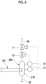
- Fig. 6 is a diagram showing an inert gas separator and a cooling device in a first modification example of the second embodiment of the present disclosure.
- a cooling device 281 that cools the mixed gas in the storage space 279 of the inert gas separator 280 may be provided separately from the heat exchanger 76 of the condenser 266.
- the cooling device 281 cools the mixed gas at the same temperature as the heat exchanger 76 of the condenser 266.
- the gas present in the storage space 279 of the inert gas separator 280 can be positively cooled and therefore, the ammonia gas contained in the gas can be condensed and can be moved into the casing 75 of the condenser 266 via the condenser communication line 82 by the self-weight.
- the ammonia contained in the gas released to the atmosphere from the atmosphere releasing line 69 can be further reduced.
- Fig. 7 is a diagram showing a configuration of a BOG treatment system according to a second modification example of the second embodiment of the present disclosure.
- a liquefied gas merging line 85 that merges the ammonia condensed in the storage space 279 of the inert gas separator 280 with the reliquefying line 67 may be provided separately from the condenser communication line 82.
- the end portion, which is connected to the inert gas separator 280, of both ends of the condenser communication line 82 is connected to the lower portion of the separator main body portion 83 of the inert gas separator 280. Further, an upper end of the liquefied gas merging line 85 is connected to the mirror plate portion 84 of the lower portion of the inert gas separator 280, and a lower end of the liquefied gas merging line 85 is merged and connected to the reliquefying line 67.
- the cooling device 281 may be provided as in the first modification example.
- the mixed gas can be smoothly introduced from the gas phase of the condenser 266 into the storage space 279 of the inert gas separator 280 via the condenser communication line 82, and the ammonia condensed in the storage space 279 of the inert gas separator 280 can be smoothly merged to the reliquefying line 67 via the liquefied gas merging line 85 by the self-weight and stored in the ammonia tank 10.
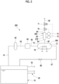
- Fig. 8 is a diagram showing a configuration of a BOG treatment system according to a third embodiment of the present disclosure.
- the floating structure 1 of the third embodiment includes the floating main structure 2, the superstructure 4, the combustion device 8, the ammonia tank 310, the fuel supply system 20, the gas supply system 30, the purge system 40, the ammonia recovery system 50, and the BOG treatment system 360. That is, the configuration is adopted in which the inert gas flows into the gas phase of the ammonia tank 310 of the third embodiment as in the first embodiment.
- the BOG treatment system 360 includes a tank tower portion (mixed gas introduction unit) 90, a cooling unit 95, an atmosphere releasing line 69, a pressure adjustment valve 70, a shutoff valve 71, a pressure detecting unit 72, and an ammonia detecting unit 73.
- the tank tower portion 90 is formed to protrude upward from the upper wall 91 of the ammonia tank 310.
- the tank tower portion 90 forms a tower space (storage space) 92 that communicates with the gas phase inside the ammonia tank 310. That is, the mixed gas present in the gas phase of the ammonia tank 310 can be stored in the tower space 92 of the tank tower portion 90.
- the tank tower portion 90 exemplified in the third embodiment includes a tower main body portion 93 that extends upward in a cylindrical shape from the upper wall of the ammonia tank 310, and a mirror plate portion 94 that closes an upper edge of the tower main body portion 93.
- the tower main body portion 93 of the present embodiment is formed to have a larger diameter than the atmosphere releasing line 69.
- the height of the tank tower portion 90 may be any height as long as the position of the upper end of the tower space 92 is higher than the uppermost portion of the gas phase of the ammonia tank 310.
- a case where the tank tower portion 90 is disposed in the central portion of the upper wall 91 of the ammonia tank 310 has been described as an example.
- the disposition of the tank tower portion 90 is not limited to the central portion of the upper wall 91.
- the cooling unit 95 cools the mixed gas in the tower space 92 in the tank tower portion 90 to liquefy the ammonia contained in the mixed gas.
- the pressure in the tower space 92 in the tank tower portion 90 is a pressure lower than the pressure in the casing 75 of the condenser 66 (for example, a pressure slightly higher than the atmospheric pressure) of the first embodiment. Therefore, the cooling unit 95 of the third embodiment has higher cooling performance than each of the cooling devices 81 of the modification example of the first embodiment described above and the first modification example of the second embodiment. In other words, the cooling unit 95 has cooling performance capable of cooling the mixed gas to a temperature at which the ammonia contained in the mixed gas can be condensed under the pressure of the gas phase of the ammonia tank 310.
- Examples of the cooling unit 95 of the third embodiment include an absorption chiller and a steam compression chiller.
- the atmosphere releasing line 69 is capable of releasing the gas in the tower space 92 to the atmosphere.
- the atmosphere releasing line 69 of the present embodiment is connected to the cooling space 77 formed in the tower space 92 at the uppermost position. Accordingly, the gas (composed substantially only of the inert gas) that is not condensed in the tower space 92 can be released to the atmosphere from the uppermost portion of the tower space 92 via the atmosphere releasing line 69.
- the pressure detecting unit 72 detects the pressure in the tank tower portion 90.
- the pressure detecting unit 72 of the present embodiment detects the internal pressure of the tower space 92.
- the internal pressure of the tower space 92 in the present embodiment is substantially the same as the pressure of the gas phase of the ammonia tank 310.
- the pressure detecting unit 72 of the present embodiment outputs the detection result to the pressure adjustment valve 70.
- the pressure adjustment valve 70 is provided in the atmosphere releasing line 69, and is capable of adjusting the pressure in the tank tower portion 90 when the inert gas is released to the atmosphere to a pressure at which the ammonia can be maintained in a liquid phase.
- the pressure adjustment valve 70 of the present embodiment automatically adjusts the valve opening degree based on the detection result of the pressure detecting unit 72 such that the pressure of the tower space 92 falls within a pressure range which is capable of maintaining the ammonia in the liquid phase. That is, by the pressure adjustment valve 70, the pressure in the tower space 92 prevents the pressure in the tower space 92 from being excessively reduced so that the ammonia condensed by the cooling unit 95 does not vaporize again in the tower space 92.
- the mixed gas in the gas phase inside the ammonia tank 310 can be introduced into the tower space 92 of the tank tower portion 90, and the mixed gas in the tower space 92 can be cooled by the cooling unit 95. Therefore, only the ammonia contained in the mixed gas can be condensed in the tower space 92, and the condensed ammonia can be moved to the ammonia tank 310 by its self-weight. In addition, since only the inert gas can remain in the tower space 92, the inert gas remained in the tower space 92 can be released into the atmosphere via the atmosphere releasing line 69.
- the inert gas present in the gas phase of the ammonia tank 310 can be easily discharged without requiring the skill of the worker. Then, by discharging the inert gas from the gas phase of the ammonia tank 310, it is possible to suppress a decrease in the reliquefaction efficiency of the BOG and a decrease in calorific value in a case where the BOG is used as fuel.
- the atmosphere releasing line 69 is connected to the tank tower portion 90. Therefore, the inert gas can be discharged from higher position. Therefore, it is possible to prevent the BOG generated from the liquid phase of the ammonia tank 310 from mixing with the gas discharged via the atmosphere releasing line 69.
- the pressure adjustment valve 70 further includes the pressure detecting unit 72 that detects the pressure in the tower space 92, and the pressure adjustment valve 70 adjusts the valve opening degree such that the pressure in the tower space 92 is within a pressure range which is capable of maintaining the ammonia in the liquid phase, based on the detection result of the pressure detecting unit 72.
- the ammonia detecting unit 73 capable of detecting the ammonia concentration in the tower space 92 and the shutoff valve 71 capable of opening and closing the atmosphere releasing line 69 are further provided. Then, the shutoff valve 71 shuts off the atmosphere releasing line 69 in a case where the ammonia concentration is higher than a predetermined upper limit value, based on the detection result of the ammonia detecting unit 73, and opens the atmosphere releasing line 69 in a case where the ammonia concentration is lower than a predetermined lower limit threshold value.
- the ammonia concentration in the tower space 92 is high, it is possible to prevent the gas containing the ammonia from being released to the atmosphere via the atmosphere releasing line 69.
- the inert gas contained in the gas phase inside the casing 75 can be removed by releasing the inert gas to the atmosphere via the atmosphere releasing line 69.
- the mixed gas is cooled inside the tank tower portion 90 into which the mixed gas of the inert gas and the ammonia is introduced, only the ammonia is condensed, and the inert gas is released into the atmosphere, and when the inert gas is released into the atmosphere, the pressure inside the tank tower portion 90 is adjusted to the pressure at which the condensed ammonia can be maintained in the liquid phase.
- the ammonia present in the gas phase in the tank tower portion 90 can be liquefied to remain only the inert gas in the gas phase in the tank tower portion 90. Then, the inert gas remaining in the gas phase can be released to the atmosphere, and thus only the inert gas contained in the mixed gas can be removed.
- the floating structure of the fourth embodiment is different from the floating structure of the third embodiment only in that the inert gas separator is provided at a position separated from the above of the ammonia tank instead of the above of the ammonia tank tower portion of the third embodiment. Therefore, the same parts as those in the third embodiment described above will be assigned by the same reference numerals, and redundant description will be omitted.
- Fig. 9 is a diagram corresponding to Fig. 8 in the fourth embodiment of the present disclosure.
- the BOG treatment system 460 includes a tank communication line 97, an inert gas separator (mixed gas introduction unit) 490, a cooling unit 95, an atmosphere releasing line 69, a pressure adjustment valve 70, a shutoff valve 71, a pressure detecting unit 72, and an ammonia detecting unit 73.
- the inert gas separator 490 is disposed above the ammonia tank 10 to form a storage space 492 capable of storing the mixed gas.
- the inert gas separator 490 of the present embodiment also has a shape elongated in the vertical direction, as in the inert gas separator 280 of the second embodiment.
- the volume of the storage space 492 in the inert gas separator 490 is smaller than the volume of the gas phase of the ammonia tank 10.
- the inert gas separator 490 of the present embodiment includes a cylindrical separator main body portion 493 and a mirror plate portion 494 that closes an upper edge and a lower edge of the separator main body portion 493.
- the atmosphere releasing line 69 of the present embodiment is connected to the mirror plate portion 494 of the upper portion of the inert gas separator 490.
- the tank communication line 97 is a pipe that allows the gas phase of the ammonia tank 310 and the storage space 492 of the inert gas separator 490 to communicate with each other.
- One end of the tank communication line 97 of the present embodiment is connected to the upper wall 91 of the ammonia tank 310, and the other end of the tank communication line 97 is connected to the mirror plate portion 494 of the lower portion of the inert gas separator 490.
- the tank communication line 97 of the present embodiment has a diameter smaller than the outer shape of the separator main body portion 493 of the inert gas separator 490 in the horizontal cross section. Since the atmosphere releasing line 69, the pressure adjustment valve 70, the shutoff valve 71, the pressure detecting unit 72, and the ammonia detecting unit 73 have the same configuration as those of the second embodiment described above, detailed description thereof will be omitted.
- the inert gas separator 490 is provided at a position separated from the above of the ammonia tank 310, and the gas phase of the ammonia tank 310 and the storage space 492 of the inert gas separator 490 are communicated with each other by the tank communication line 97.
- the mixed gas present in the gas phase of the ammonia tank 310 is guided to the storage space 492 of the inert gas separator 490 via the tank communication line 97, and the ammonia contained in the mixed gas can be condensed by the cooling unit 95 in the storage space 492 of the inert gas separator 490. Therefore, only the inert gas remaining without being condensed in the storage space 492 of the inert gas separator 490 can be discharged via the atmosphere releasing line 69.
- the ammonia condensed in the storage space 492 can be moved to the ammonia tank 310 by its self-weight via the tank communication line 97.
- the inert gas separator 490 may be connected to the ammonia tank 310 via the tank communication line 97, it is possible to easily increase the storage space 492 even in the existing ammonia tank.
- the mixed gas is cooled inside the inert gas separator 490 into which the mixed gas of the inert gas and the ammonia is introduced, only the ammonia is condensed, the inert gas is released into the atmosphere, and when the inert gas is released into the atmosphere, the pressure inside the inert gas separator 490 is adjusted to the pressure at which the condensed ammonia can be maintained in a liquid phase.
- the floating structure of the fifth embodiment is different from the floating structure of the third embodiment only in that the ammonia tank of the third embodiment described above is used as the pressure tank, and the liquefied ammonia stored in the storage tank serving as the other ammonia tank is used as the refrigerant of the cooling unit 95. Therefore, the same parts as those of the third embodiment described above will be assigned by the same reference numerals with reference to Fig. 1 , and the description thereof will be omitted.
- Fig. 10 is a diagram corresponding to Fig. 9 in the fifth embodiment of the present disclosure.
- the floating structure 1 of the fifth embodiment includes the floating main structure 2, the superstructure 4, the combustion device 8, the ammonia tank 510, the storage tank 101, the fuel supply system 20, the gas supply system 30, the purge system 40, the ammonia recovery system 50, and the BOG treatment system 560.
- the tank that stores the ammonia the ammonia tank (high-pressure tank) 510 that stores the ammonia at a pressure higher than the atmospheric pressure, and the storage tank (low-pressure tank) 101 that stores the ammonia at a lower temperature and a lower pressure than the ammonia tank 510 are provided.
- the ammonia tank 510 is a so-called pressure tank capable of storing the liquefied ammonia in a state of a pressure higher than an atmospheric pressure and a temperature higher than that of the storage tank 101 (for example, a room temperature).
- Examples of the ammonia tank 510 include a service tank and a mixing chamber.
- at least the ammonia tank 510 is configured to allow the mixed fluid of the inert gas and the ammonia discharged by the purge system 40 of the first embodiment described above to flow in via the recovery line 52.
- the storage tank 101 is, for example, a cargo tank or the like, and examples thereof include a tank that stores liquefied ammonia in a predetermined pressure range close to an atmospheric pressure.
- the storage tank 101 is covered with a heat insulating material that suppresses heat input from the outside, and the ammonia stored in the storage tank 101 is held at a temperature (low temperature) at which the liquid phase can be maintained at the predetermined pressure.
- the ammonia tank 10 capable of reliquefying the BOG by the BOG treatment system 60 of the first embodiment may be used as the storage tank 101.
- the BOG treatment system 560 of the fifth embodiment includes the tank tower portion (mixed gas introduction unit) 90, the cooling unit 595, the atmosphere releasing line 69, the pressure adjustment valve 70, the shutoff valve 71, the pressure detecting unit 72, and the ammonia detecting unit 73. Since the atmosphere releasing line 69, the pressure adjustment valve 70, the shutoff valve 71, the pressure detecting unit 72, and the ammonia detecting unit 73 have the same configuration as those in the third embodiment, detailed description thereof will be omitted.
- the tank tower portion 90 protrudes upward from the upper wall 591 of the ammonia tank 510.
- the tank tower portion 90 forms a tower space (storage space) 92 that communicates with the gas phase inside the ammonia tank 10. That is, the mixed gas present in the gas phase of the ammonia tank 510 can be stored in the tower space 92 of the tank tower portion 90.
- the tank tower portion 90 exemplified in the fifth embodiment has the same configuration as the tank tower portion 90 of the third embodiment, and includes the tower main body portion 93 that extends upward in a cylindrical shape from the ammonia tank 510, and the mirror plate portion 94 that closes the upper edge of the tower main body portion 93.
- the cooling unit 595 cools the mixed gas in the tank tower portion 90 to a temperature at which only the ammonia in the mixed gas can be condensed.
- the cooling unit 595 includes the refrigerant pump 102, the refrigerant supply line 103, the cooling unit main body 104, and the refrigerant introduction line 105.
- the refrigerant pump 102 pumps the low-temperature ammonia stored in the storage tank 101 toward the cooling unit main body 104.
- the refrigerant supply line 103 is a pipe that guides the low-temperature ammonia ejected from the refrigerant pump 102.
- the refrigerant supply line 103 supplies the low-temperature ammonia ejected from the refrigerant pump 102 to the cooling unit main body 104.
- the cooling unit main body 104 is a so-called heat exchanger and is disposed in the tower space 92.
- the cooling unit main body 104 exchanges heat between the low-temperature ammonia supplied via the refrigerant supply line 103 and the mixed gas in the tower space 92. As a result, only the ammonia contained in the mixed gas in the tower space 92 is condensed.
- the refrigerant introduction line 105 supplies the ammonia as a refrigerant, which is heat-exchanged with the mixed gas by the cooling unit main body 104, into the ammonia tank 510.
- the mixed gas in the tower space 92 of the tank tower portion 90 can be cooled by using the low-temperature ammonia stored in the storage tank 101 as a refrigerant, and only the ammonia can be condensed.
- the ammonia used as the refrigerant can be stored in the liquid phase of the ammonia tank 510, it is also possible to suppress a temperature rise in the liquid phase of the ammonia tank 510.
- Fig. 11 is a diagram corresponding to Fig. 10 in a modification example of the fifth embodiment of the present disclosure.
- the cooling unit 595 of the fifth embodiment can also be applied to a configuration including the inert gas separator 490 as in the fourth embodiment.
- the cooling unit main body 104 of the cooling unit 595 may be installed in the storage space 492 of the inert gas separator 490 provided at a position separated from the above of the ammonia tank 510.
- the shape of the condenser tower portion 80, the tank tower portion 90, and the inert gas separator 280 and 490 is not limited to the shapes of the above-described respective embodiments and modification examples as long as the tower space 79 and 92 and the storage space 279 and 492 can be formed.
- the casing 75 has the condenser tower portion 80 has been described.
- the space may be used as the tower space 79, and the condenser tower portion 80 may be omitted.
- shutoff valve 71 In each of the above-described embodiments and modification examples, a case where the closed shutoff valve 71 is opened in a case where the ammonia concentration is reduced to equal to or lower than the lower limit threshold value has been described. However, the shutoff valve 71 may be gradually opened.
- the atmosphere releasing line 69 of each of the embodiments and the modification examples may be provided with a sensor that detects the flow of the inert gas on the downstream side of the shutoff valve 71.
- the floating structure 1 is a ship that can navigate by a main engine or the like.
- the floating structure is not limited to a ship as long as the floating structure is capable of storing ammonia.
- the inert gas mixed in the gas phase of the ammonia tank is removed by the fuel purging.
- the inert gas mixed in the gas phase of the ammonia tank is not limited to the inert gas mixed by the fuel purging.
- the gas may be a seal gas of a compressor.
- the pressure adjustment valve 70 and the shutoff valve 71 provided in the atmosphere releasing line 69 are automatically controlled based on the detection results of the pressure detecting unit 72 and the ammonia detecting unit 73.
- the pressure adjustment valve 70 and the shutoff valve 71 may be manually operated by the worker, respectively, based on the detection results of the pressure detecting unit 72 and the ammonia detecting unit 73.
- the inert gas is released into the atmosphere via the atmosphere releasing line 69.
- the inert gas may be released into the atmosphere via a removal device (not shown) capable of removing ammonia.
- the floating structure described in the embodiment is ascertained as follows.
- Examples of the floating structure 1 include a ship.
- Examples of the inert gas include a nitrogen gas.
- the inert gas can be easily discharged.
Landscapes
- Engineering & Computer Science (AREA)
- Mechanical Engineering (AREA)
- Chemical & Material Sciences (AREA)
- General Engineering & Computer Science (AREA)
- Combustion & Propulsion (AREA)
- Ocean & Marine Engineering (AREA)
- Analytical Chemistry (AREA)
- General Chemical & Material Sciences (AREA)
- Oil, Petroleum & Natural Gas (AREA)
- Chemical Kinetics & Catalysis (AREA)
- Filling Or Discharging Of Gas Storage Vessels (AREA)
Applications Claiming Priority (2)
| Application Number | Priority Date | Filing Date | Title |
|---|---|---|---|
| JP2021207357A JP2023092231A (ja) | 2021-12-21 | 2021-12-21 | 浮体及び浮体の不活性ガス排出方法 |
| PCT/JP2022/043530 WO2023120031A1 (ja) | 2021-12-21 | 2022-11-25 | 浮体及び浮体の不活性ガス排出方法 |
Publications (2)
| Publication Number | Publication Date |
|---|---|
| EP4434871A1 true EP4434871A1 (de) | 2024-09-25 |
| EP4434871A4 EP4434871A4 (de) | 2025-09-03 |
Family
ID=86902342
Family Applications (1)
| Application Number | Title | Priority Date | Filing Date |
|---|---|---|---|
| EP22910749.5A Pending EP4434871A4 (de) | 2021-12-21 | 2022-11-25 | Schwimmkörper und verfahren zum abführen von inertgas aus einem schwimmkörper |
Country Status (5)
| Country | Link |
|---|---|
| EP (1) | EP4434871A4 (de) |
| JP (1) | JP2023092231A (de) |
| KR (1) | KR20240107332A (de) |
| CN (1) | CN118401433A (de) |
| WO (1) | WO2023120031A1 (de) |
Families Citing this family (4)
| Publication number | Priority date | Publication date | Assignee | Title |
|---|---|---|---|---|
| CN112696289B (zh) * | 2020-12-28 | 2024-07-26 | 大连船舶重工集团有限公司 | 一种船用液氨燃料供给及燃料回收利用系统 |
| WO2025034068A1 (ko) | 2023-08-10 | 2025-02-13 | 주식회사 엘지에너지솔루션 | 전고체 전지용 양극 및 이를 포함하는 전고체 전지 |
| WO2025190761A1 (en) * | 2024-03-13 | 2025-09-18 | Lge Ip Management Company Ltd | Method and system for recovering fuel from an engine |
| WO2025253864A1 (ja) * | 2024-06-04 | 2025-12-11 | 株式会社Ihi | 回収装置 |
Family Cites Families (16)
| Publication number | Priority date | Publication date | Assignee | Title |
|---|---|---|---|---|
| KR100638925B1 (ko) * | 2005-01-18 | 2006-10-26 | 대우조선해양 주식회사 | 엘엔지선의 증발가스 과냉액화 운전시스템 |
| US20060156758A1 (en) * | 2005-01-18 | 2006-07-20 | Hyung-Su An | Operating system of liquefied natural gas ship for sub-cooling and liquefying boil-off gas |
| WO2012118317A2 (ko) * | 2011-02-28 | 2012-09-07 | 한국과학기술원 | Lng주유시스템 및 증발가스 처리방법 |
| WO2015048420A1 (en) * | 2013-09-27 | 2015-04-02 | Excelerate Energy Limited Partnership | Apparatus, system and method for the capture, utilization and sendout of latent heat in boil off gas onboard a cryogenic storage vessel |
| JP6694645B2 (ja) * | 2016-03-01 | 2020-05-20 | 国立研究開発法人産業技術総合研究所 | 塩基性ガス吸収剤及び塩基性ガス分離回収方法 |
| JPWO2017149718A1 (ja) | 2016-03-03 | 2018-12-27 | 日揮株式会社 | アンモニアの製造方法 |
| KR102265257B1 (ko) * | 2016-03-07 | 2021-06-16 | 현대중공업 주식회사 | 증발가스 재액화 시스템 및 선박 |
| KR20200049933A (ko) * | 2018-10-29 | 2020-05-11 | 삼성중공업 주식회사 | 부유식 플랫폼 |
| KR102377799B1 (ko) * | 2020-02-17 | 2022-03-23 | 한국조선해양 주식회사 | 가스 처리 시스템 및 이를 포함하는 선박 |
| KR102776645B1 (ko) * | 2020-05-07 | 2025-03-10 | 삼성중공업 주식회사 | 암모니아 연료 공급 장치 |
| KR102755885B1 (ko) * | 2020-05-22 | 2025-01-20 | 한화오션 주식회사 | 선박용 연료 공급 시스템 |
| JP6859475B1 (ja) * | 2020-08-06 | 2021-04-14 | 三菱造船株式会社 | 船舶 |
| JP6934555B1 (ja) * | 2020-08-25 | 2021-09-15 | 三菱造船株式会社 | 船舶 |
| CN112696289B (zh) * | 2020-12-28 | 2024-07-26 | 大连船舶重工集团有限公司 | 一种船用液氨燃料供给及燃料回收利用系统 |
| JP7661127B2 (ja) * | 2021-05-24 | 2025-04-14 | 三菱造船株式会社 | 船舶 |
| CN113719385B (zh) * | 2021-09-09 | 2024-11-12 | 大连船舶重工集团有限公司 | 一种船用管线液氨回收系统 |
-
2021
- 2021-12-21 JP JP2021207357A patent/JP2023092231A/ja active Pending
-
2022
- 2022-11-25 KR KR1020247020060A patent/KR20240107332A/ko active Pending
- 2022-11-25 EP EP22910749.5A patent/EP4434871A4/de active Pending
- 2022-11-25 WO PCT/JP2022/043530 patent/WO2023120031A1/ja not_active Ceased
- 2022-11-25 CN CN202280083412.9A patent/CN118401433A/zh active Pending
Also Published As
| Publication number | Publication date |
|---|---|
| CN118401433A (zh) | 2024-07-26 |
| EP4434871A4 (de) | 2025-09-03 |
| WO2023120031A1 (ja) | 2023-06-29 |
| KR20240107332A (ko) | 2024-07-09 |
| JP2023092231A (ja) | 2023-07-03 |
Similar Documents
| Publication | Publication Date | Title |
|---|---|---|
| EP4434871A1 (de) | Schwimmkörper und verfahren zum abführen von inertgas aus einem schwimmkörper | |
| KR102802044B1 (ko) | 가스 처리 시스템 및 이를 포함하는 선박 | |
| EP4353584A1 (de) | Schiff | |
| CN112437738A (zh) | 气体处理系统以及包括气体处理系统的船舶 | |
| KR20100099441A (ko) | 재액화 기능을 가지는 전기추진 lng 운반선의 증발가스 처리장치 및 방법 | |
| JP7684322B2 (ja) | ガス処理システム及びそれを含む船舶 | |
| KR100912169B1 (ko) | 응축액 순환장치 및 순환방법 | |
| EP4538169A1 (de) | Schwimmkörper | |
| EP4357234A1 (de) | Schwimmkörper | |
| KR102019271B1 (ko) | 선박 연료가스 공급 시스템의 부분 재액화 시스템용 열교환기 세정 장치 및 방법 | |
| KR100839771B1 (ko) | 해상 구조물에 구비되는 질소 생산장치 및 상기 질소생산장치를 이용한 해상 구조물에서의 질소 생산방법 | |
| KR20230168626A (ko) | 선박의 암모니아 연료공급시스템 | |
| KR102808422B1 (ko) | 선박의 연료전지용 암모니아 연료 공급 시스템 | |
| EP4524026A1 (de) | Schwimmende struktur | |
| KR20240106574A (ko) | 연료전지용 암모니아 회수 시스템 및 방법 | |
| KR20250110416A (ko) | 암모니아연료추진선박 | |
| KR20230165990A (ko) | 선박의 암모니아 연료공급시스템 | |
| KR20220139754A (ko) | 연료 공급 시스템 | |
| KR20140084833A (ko) | 연료가스를 이용한 퍼징 시스템 |
Legal Events
| Date | Code | Title | Description |
|---|---|---|---|
| STAA | Information on the status of an ep patent application or granted ep patent |
Free format text: STATUS: THE INTERNATIONAL PUBLICATION HAS BEEN MADE |
|
| PUAI | Public reference made under article 153(3) epc to a published international application that has entered the european phase |
Free format text: ORIGINAL CODE: 0009012 |
|
| STAA | Information on the status of an ep patent application or granted ep patent |
Free format text: STATUS: REQUEST FOR EXAMINATION WAS MADE |
|
| 17P | Request for examination filed |
Effective date: 20240617 |
|
| AK | Designated contracting states |
Kind code of ref document: A1 Designated state(s): AL AT BE BG CH CY CZ DE DK EE ES FI FR GB GR HR HU IE IS IT LI LT LU LV MC ME MK MT NL NO PL PT RO RS SE SI SK SM TR |
|
| DAV | Request for validation of the european patent (deleted) | ||
| DAX | Request for extension of the european patent (deleted) | ||
| A4 | Supplementary search report drawn up and despatched |
Effective date: 20250806 |
|
| RIC1 | Information provided on ipc code assigned before grant |
Ipc: B63B 25/08 20060101AFI20250731BHEP Ipc: B63B 25/16 20060101ALI20250731BHEP Ipc: B63J 2/14 20060101ALI20250731BHEP Ipc: F17C 13/00 20060101ALI20250731BHEP Ipc: B01D 53/00 20060101ALI20250731BHEP Ipc: F17C 9/00 20060101ALI20250731BHEP Ipc: B63B 17/00 20060101ALI20250731BHEP Ipc: F17C 13/02 20060101ALI20250731BHEP |