EP4433397B1 - Dispositif de levage pour plateaux à oeufs - Google Patents
Dispositif de levage pour plateaux à oeufs Download PDFInfo
- Publication number
- EP4433397B1 EP4433397B1 EP23723674.0A EP23723674A EP4433397B1 EP 4433397 B1 EP4433397 B1 EP 4433397B1 EP 23723674 A EP23723674 A EP 23723674A EP 4433397 B1 EP4433397 B1 EP 4433397B1
- Authority
- EP
- European Patent Office
- Prior art keywords
- platform
- egg
- egg tray
- lifting device
- tray
- Prior art date
- Legal status (The legal status is an assumption and is not a legal conclusion. Google has not performed a legal analysis and makes no representation as to the accuracy of the status listed.)
- Active
Links
Images


Classifications
-
- B—PERFORMING OPERATIONS; TRANSPORTING
- B65—CONVEYING; PACKING; STORING; HANDLING THIN OR FILAMENTARY MATERIAL
- B65G—TRANSPORT OR STORAGE DEVICES, e.g. CONVEYORS FOR LOADING OR TIPPING, SHOP CONVEYOR SYSTEMS OR PNEUMATIC TUBE CONVEYORS
- B65G57/00—Stacking of articles
- B65G57/30—Stacking of articles by adding to the bottom of the stack
- B65G57/301—Stacking of articles by adding to the bottom of the stack by means of reciprocatory or oscillatory lifting and holding or gripping devices
- B65G57/302—Stacking of articles by adding to the bottom of the stack by means of reciprocatory or oscillatory lifting and holding or gripping devices added articles being lifted to substantially stationary grippers or holders
-
- B—PERFORMING OPERATIONS; TRANSPORTING
- B65—CONVEYING; PACKING; STORING; HANDLING THIN OR FILAMENTARY MATERIAL
- B65G—TRANSPORT OR STORAGE DEVICES, e.g. CONVEYORS FOR LOADING OR TIPPING, SHOP CONVEYOR SYSTEMS OR PNEUMATIC TUBE CONVEYORS
- B65G2201/00—Indexing codes relating to handling devices, e.g. conveyors, characterised by the type of product or load being conveyed or handled
- B65G2201/02—Articles
- B65G2201/0202—Agricultural and processed food products
- B65G2201/0208—Eggs
Definitions
- the present invention relates to a lifting device for the gripping on the underside and carrying of egg trays.
- Egg trays are available in various types and sizes.
- a widely used form is an egg tray in which eggs are, or at least should be, packed in a matrix pattern of five rows and six columns.
- Thirty cups in which the eggs are, or at least should be, placed are formed as cups with a shape that is midway between an inverted truncated pyramid and an inverted dome.
- the device according to the present invention has been developed in particular for an egg tray of this kind. It ought to be clear, however, that other shapes of egg trays, for example with a matrix of four by five columns, may also be processed with a device according to the invention, as also occurs with known devices. That is possible because the orientation and the distance apart of the eggs in most cases, even with egg trays that are not square but are for example rectangular, coincides with that in the familiar square five by six egg tray.
- the present invention relates to the last-mentioned method.
- Filled egg trays to be stacked are usually transported on a supply conveyor, such as an endless belt, to a receiving device positioned under a stacking location of a stacking device.
- the egg tray is raised from the receiving device by a platform.
- the platform is provided with a profile with upward-projecting projections, which fit into raised portions of the egg trays. In this way it is possible to ensure that the projections of the egg tray are aligned well relative to the cups of an upper egg tray.
- the projections of the egg tray engage with cups of a superjacent egg tray and the stack is optionally turned by a defined amount and put back again at the stacking location.
- KR 101 951 299 B1 discloses a lifting device according to the preamble of claim 1.
- the present invention aims to provide a lifting device wherein a more regular pattern of movements and/or fewer movements are necessary than with the known lifting devices. This is achieved according to the present invention by configuring a lifting device according to claim 1.
- platforms a) with upward-projecting projections and b) with holes extending through the platform or blind holes, work per se in the same way.
- the conical shape of platforms according to alternative a) provides, between the projections, a suitable receiving space for cups of an egg tray to be carried.
- platforms according to alternative b) the cups of the egg trays are received with sufficient support in the holes of the platform.
- the projections engage on the ribs of an egg tray that are positioned between the cups of the egg tray, but also between the raised portions. However, on account of the patterns of the projections and the holes, the projections and holes are located at the same place when one of the two is turned 90 degrees every time about a vertical. Since a platform according to the invention is turned exactly 90 degrees between two lifting movements, the action of the two alternatives is identical.
- Egg trays are available in various types and sizes.
- a widely used form is a square egg tray in which eggs are, or at least should be, packed in a matrix pattern of five rows and six columns.
- the cups in which the eggs are, or at least should be, placed are formed as cups with a shape that is midway between an inverted truncated cone and an inverted dome.
- the device according to the present invention has been developed in particular for an egg tray of this kind. It should, however, be clear that other shapes of egg trays may also be processed with a device according to the invention, which also occurs with known devices. That is possible because the orientation and the distance apart of the eggs in most cases, even with egg trays that are not square but are for example rectangular, coincides with that in the known square five by six egg tray.
- a platform according to the present invention is suitable for engaging on an egg tray from below in two orientations turned 90 degrees relative to each other, wherein always half of the projections engage on the underside of the egg tray, or wherein always half of the holes engage on a recess of the egg tray.
- the platform with an egg tray can be raised, and between the engagement of the egg tray on the upper egg tray and the depositing of the stack of egg trays at the stacking location they are turned 90 degrees about a (virtual) vertical rotation axis, wherein the platform does not need to be turned back to the original orientation to engage a subsequently supplied egg tray and raise it.
- the projections do not come into contact with a recess of an egg tray that is placed on the platform; it is a number of bridges or ribs, but not all bridges/ribs, between two adjacent cups of an egg tray, that rest on a projection during use. In the two positions of an egg tray turned 90 degrees relative to each other, it is thus always other projections that engage on bridges/ribs on the underside of an egg tray. This will be explained in more detail later in the description of the invention, referring to the drawing.
- the lifting device is configured for rotating the platform about a vertical axis, in particular through 90 degrees.
- the platform can turn a further 90 degrees every time in two successive cycles, or turn to and fro.
- a stack of eggs with a supplied lower egg tray can be turned to make it suitable for engaging with a following egg tray from below, as already discussed above.
- the length and/or width of the platform is less than the length and the width of an egg tray; an edge of an egg tray located on the platform will project beyond the platform, so that the respective edge is free to be able to engage with it from below, for example on a carrying element on which the egg tray or a stack of egg trays is to be deposited by means of the lifting device.
- the length and/or the width of the platform is preferably less than 250 mm, and more preferably less than 220 mm.
- the platform When the platform is provided, on an upper side thereof, with upward-projecting projections, which are configured for being able to engage, in two positions turned 90 degrees about a vertical axis, with an underside of an egg tray that is to be carried, the platform does not need to turn back to an original position every time after it has turned 90 degrees in order to place an egg platform, turned a quarter turn, under an egg platform located above.
- the platform when the platform is provided with holes extending through the platform or with blind holes, said holes extending through the platform or blind holes being configured for being able to receive, in two positions turned 90 degrees about a vertical axis, cups of an egg tray to be carried, the platform does not need to turn back to an initial position every time after it has turned 90 degrees in order to place an egg platform, turned a quarter turn, under an egg platform located above.
- the platform is rectangular, preferably square, it can extend parallel to the edges of an egg tray to be supported.
- other shapes such as octagonal or round, are also conceivable for the platform and may be functional.
- the projections or holes always form a pattern of the five of a dice.
- the distance apart of the outermost points is equal to that of the center distance of an egg tray to be engaged, to which reference is made in claim 1.
- the distance between two adjacent vertexes of said five of the dice is between 40 and 60 mm, preferably between 42 and 55 mm, and in particular is 48.3 mm.
- the center distance is admittedly related to the cups of a specific (five by six) egg tray, but it should be clear that said center distance in this document may be projected onto the platform, i.e. the platform is configured to receive an egg tray with said pattern.
- a projection preferably all projections, has/have a flat top surface that is horizontal during use.
- the base of a projection has a diameter from 20 to 40 mm, preferably from 25 to 35 mm, and more preferably of 28-32 mm.
- the base of the projection has an oval shape.
- a platform may be used for egg trays with relatively large and relatively small cups.
- the oval shape at the underside of the projections, which may become round toward the top, may be used for engaging with the relatively wide sides of cups of the relatively small egg trays, and engaging with the relatively narrow side and centering of relatively large egg trays.
- the height of a projection is between 7.5 and 15 mm, preferably between 10 and 14 mm, and in particular 13.75 mm.
- the holes have a round cross section, or are at least point-symmetric relative to a center of the respective hole. Said shape provides a suitable receiving space for cups of an egg tray to be carried, So that the cups of the egg trays are received with sufficient support in the holes of the platform, it is preferred that the holes have a diameter of more than 25 mm, more preferably more than 30 or 35 mm.
- the lifting device For transmitting a drive to the platform of a lifting and optionally rotating motion, the lifting device preferably comprises an elongated lifting element extending vertically, provided on the underside of the platform.
- the invention relates to a lifting device with an egg tray thereon with a matrix pattern of X rows and Y cups, in each of which an egg is placed.
- X is 3, 4 or 5.
- Y is 4, 5, or 6.
- a recess is formed as a depression with substantially a shape of an inverted truncated pyramid, as a depression with substantially a shape of an inverted dome or an intermediate form thereof.
- Egg trays are generally known and the shape thereof is easily deduced.
- cups of the egg tray when used on a base surface of the platform located between the projections of the platform, are supported on the platform.
- the base surface of the platform is flat, and more preferably extends horizontally.
- the present invention is usable as the lifting device in a stacking device that is suitable for stacking substantially square egg trays, supplied, or at least to be supplied, by means of a supply conveyor in a supply transport direction under a stacking location, and to be discharged via a discharge conveyor in a discharge transport direction from the stacking location, comprising:
- Known stacking devices of the type described above have, as second carrying elements, four strips defining a rectangle, each hinged about a horizontal axis.
- Two second carrying elements are fitted to, and rest on horizontal edges of the stacking location.
- the other two second carrying elements extend at right angles to the discharge transport direction and rest with their ends on the second carrying elements mentioned in the previous sentence.
- a disadvantage of the known device is that the action of the second carrying elements is fault-prone and it is able to support an egg tray better.
- the second carrying elements arranged at right angles to the discharge transport direction cannot drop downward earlier than the second carrying elements that are carried by and rest on the edges of the stacking location, because otherwise they tilt downward completely.
- the known second carrying elements can only carry an egg tray over a narrow bottom edge of an egg tray.
- Egg trays are often made of bulk material, which is very fragile, and becomes very weak if it gets just a bit wet. This has a considerable effect on the carrying capacity of the thin bottom edge of the egg tray. When a stack of egg trays drops downward in the device this produces a lot of rubbish. The device must remain clean, since foodstuffs are being packed by it.
- the stacking device can carry a stack of egg trays in a more reliable manner and is not very fault-prone, because the second carrying elements extend at least substantially horizontally and at right angles to the discharge transport direction and are configured to move in a horizontal plane in the transport direction away from each other and toward each other.
- the motion of the second carrying elements may be motor-controlled and is therefore less fault-prone than in the known device, wherein the motion of the second carrying elements depends on contact with egg trays, and on gravity.
- the invention offers the possibility of positioning the second carrying elements better and the design freedom thereof is greater, so that they can be designed better according to their function,
- a further advantageous effect is that the passage, in the direction at right angles to the discharge transport direction, only needs to be minimally wider than the corresponding dimension of an egg tray, and that in addition it can remain free from parts moving uncontrollably.
- Another advantageous effect is that the tray only needs to extend minimally above the horizontal plane of the upper transit space, because the carrying elements move a small distance from each other in the same horizontal plane.
- the second carrying elements are elongated, they can carry an egg tray over a relatively large length, substantially the whole length or width thereof, without needing to be bulkier.
- cups of the egg tray between the projections rest on the platform, preferably on a plane from which the projections extend upward.
- the projections themselves thus do not need to engage with their upper sides directly on an egg tray.
- the second carrying elements have a longitudinal direction that extends at right angles to the discharge transport direction and a transverse direction, seen from bottom to top, extending slanting toward each other.
- the slant angle preferably corresponds substantially to the slant angle of a corresponding edge of an egg tray to be carried, so that the second carrying elements can engage on the egg tray reliably over a part of or almost the whole height of the corresponding edge of the egg tray.
- the second carrying elements may comprise a strip extending, in use, transversely to the discharge transport direction, on which there are for example six lips extending slanting upward.
- first carrying elements extend in the supply transport direction.
- the respective two first carrying elements may be mounted in the extension of the supply transport device, so that an egg tray can be pushed as it were by the supply conveyor belt with the lateral edges on the respective two first carrying elements.
- the platform has a rectangular, preferably square perimeter.
- Said shape corresponds to the shape of the most used five by six egg tray and can thus support it well.
- other shapes are also possible, such as a rectangular shape wherein the length differs from the width, or an octagonal or round shape.
- the perimeter of the platform has a length and a width that are in each case smaller than the length and width, respectively, of a five by six tray [length width tray], wherein the length and/or width are preferably less than 250 mm, more preferably less than 220 mm.
- the platform is provided, on an upper side thereof, with upward-projecting projections, which are configured for being able to engage, in two positions turned 90 degrees about a vertical axis, with an underside of an egg tray that is to be carried.
- an egg tray carried on the platform can be carried, aligned more reliably and possibly better relative to an egg tray at the stacking location, and moved to the stacking location.
- the carrying device comprises an elongated lifting element extending vertically, provided on the underside of the platform. Accordingly, by means of a lifting drive known per se, an upward and downward motion can be transmitted to the platform easily, and the weight to be transferred can be limited.
- the carrying device is configured for rotating the platform about a vertical axis, the platform can rotate an egg tray through an angle of 90 degrees. This is advantageous, since egg platforms should always be stacked turned 90 degrees relative to each other.
- the discharge transport device comprises an endless belt, on which stacked egg trays are placed. If the stack is up to height, i.e. if the desired number of egg trays has been stacked, the rear carrier remains open and the front holder drops down with it. The stacks are led away like this.
- the receiving device and/or the stacking location extend at least substantially in a horizontal plane. However, for example when a supply or discharge transport device is oriented slanting relative to the horizontal, the receiving device and/or the stacking location may extend at an angle relative to the horizontal.
- the lifting device according to the present invention may be used in a method for stacking egg trays, comprising the steps of:
- the egg trays are stacked by means of a stacking device according to the first aspect of the invention.
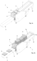
- Figs. 1a and 1b show, respectively, a perspective view of an empty stacking device 1 for egg trays, in which a device according to the present invention is incorporated, and a perspective view of the stacking device 1, filled with egg trays stacked and to be stacked 8, 9.
- the stacking device comprises a conveyor belt 2 as supply conveyor that forms part of a supply transport device in which, in a manner known per se, eggs are packed in egg trays.
- egg trays to be stacked 8 in this case filled with five rows and six columns of eggs, are supplied via conveyor belt 2.
- the egg trays come into a receiving device 3, where they are brought upward by a lifting device 4 toward stacked egg trays 9 carried by second carrying elements in the form of a front and a rear carrier 5, 6.
- Egg trays 9 stacked to a desired height are deposited by the lifting device 4 on the conveyor belt 2, with which the separate egg trays are supplied, and the conveyor belt 2 transports the stacked egg trays to a discharge conveyor in the form of a conveyor belt 7, via which the stacked egg trays 9 are led away.
- the discharge conveyor forms part of a discharge transport device that drives the conveyor belt 7 and by which the stacked egg trays 9 may be fed for example to a palletizing device.
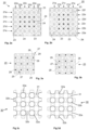
- Figs. 2a and 2b show a bottom view of an egg tray 20.
- This egg tray has a matrix pattern of five rows 21a-21e and six columns 22a-22f with cups 23, in which eggs are placed during use. Note that, because the underside of an egg tray 20 is shown here, the eggs are located on the side of the figures turned away from the side in view.
- the egg tray from Fig. 2b is shown turned through 90 degrees anticlockwise relative to the egg tray from Fig. 2a . Between the cups 23 there are raised portions 24 (in these figures, away from the viewer) which in the case of stacked egg trays 9, carry cups 23 of egg tray 20 stacked thereon.
- Figs. 3a and 3b show a top view of platform 25 for carrying and for raising and lowering egg trays.
- the flat base surface 26, and the projections 27 with their base 28 and flat upper surface 29 of the platform 25 can be seen in the top view.
- the platform 25 is shown in Figs. 3a and 3b in the same orientation with supporting points shown for an egg tray 20 that is turned 90 degrees.
- the egg trays 20 are always supplied oriented identically and it is the platform 25 that, turned 90 degrees every time, engages on the next egg trays 20.
- the platform 25 may of course also be used with stacking devices wherein egg trays 20 are supplied turned 90 degrees every time.
- Figs. 3c and 3d show a top view of platform 30 for carrying and for raising and lowering egg trays.
- the flat base surface 31 and the through holes 32 in the platform 30 can be seen in the top view.
- the holes 32a in the base surface, which in use receive cups 23 of an egg tray 20, are marked with black lines.
- the holes 32b in the base surface, which in use receive cups 23 of an egg tray 20, are marked with black lines.
- the platform 30 is shown in Figs. 3c and 3d in the same orientation with supporting points shown for an egg tray 20 that is turned 90 degrees.
- successive egg trays 20 are always supplied oriented identically and it is the platform 30 that, turned 90 degrees every time, engages on the next egg trays 20.
- the platform 30 may of course also be used with stacking devices wherein egg trays 20 are supplied turned 90 degrees every time.
- blind holes may also be provided in platform 30, which are at least formed so that cups of egg trays can be received therein.
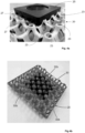
- Fig. 4a shows a perspective bottom view (rotated 180 degrees) of the platform 25 that supports an egg tray 20 (because the arrangement is photographed upside down, the bottom ends of the eggs do not come into contact with the cups. It should be clear, however, that if the arrangement is reversed and the egg tray 20 is located on platform 25, the eggs rest in the cups 23). It can be seen in this figure that some cups 23 of the egg tray 20 rest on the flat base surface 26 of the platform 25. On their side, the projections 27 of the egg tray 20 relative to the platform 25 help centering (or vice versa), not only in the state in which the egg tray 20 rests completely on the platform 25, but certainly also while bringing the platform 25 under the egg tray 20. The upper surfaces of the projections 27 do not come into contact with the egg tray 20.
- Fig. 4b shows a perspective bottom view of a platform 30 with holes 32a, 32b extending through the platform 30 that supports an egg tray 20. It can be seen in this figure that some cups 23 of the egg tray 20 rest on the edges of holes 32a of the platform 30. The holes 32a center the cups 23 of the egg tray 20 relative to the platform 30, not only in the state in which the egg tray 20 rests completely on the platform 30, but certainly also while bringing the platform 30 under the egg tray 23.
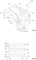
- Fig. 5 shows a perspective view of a lifting device 40.
- the lifting device 40 has a driven guide wheel 41 rotating, or at least rotatable, about a rotation axis 50.
- the guide wheel 41 is of solid configuration in this embodiment example.
- In the side surface 44 of the guide wheel 41 there is an oval groove 45.
- a platform 25 is carried by a lifting element in the form of a rod 46. Underneath the rod 46 there is a cam wheel 47 extending at right angles to the rod 46, with cams 48, which project outwards in the plane of the cam wheel 47. Next to the side of the guide wheel 41 there is a rocker arm 49 with an axis 50 that extends at right angles to the plane of the guide wheel 41 into the oval groove 45. The rocker arm 49 is connected to a transmitting device 51 that carries the rod 46 with the cam wheel 47.
- the rocker arm 49 When guide wheel 41 rotates, the rocker arm 49 performs a rocking motion, which is converted via transmitting device 51 to a vertical up and down motion of the rod 46 with the platform 25 and the cam wheel 47.
- the slot 43 of the guide wheel 41 engages on one of the cams 48 of the cam wheel 47.
- the deflection 43b moves the respective cam 47 sideways, so that rod 46 with platform 25 is turned through 90 degrees. Then the guide wheel 41 turns further again, so that the rocker arm 49 moves the rod 46 down again via the transmitting device 51.
- Fig. 6a shows stacked egg trays 9 in side view. It can be seen in Fig. 6 that the egg trays 20 stacked on one another are oriented relative to each other turned a quarter turn, i.e. 90 degrees every time. Of the upper egg tray 20, only the outermost row 21e of eggs can be seen. In the egg tray 20 located thereunder, the outermost column 22a of eggs can be seen. In the egg tray 20 located thereunder, the outermost row (21a, not visible in Fig. 6a ) of eggs is obstructed behind the superjacent egg tray 20. In the egg tray 20 located thereunder, again an outermost column 22f of eggs is visible. The bottom egg tray is carried by a front carrier 5 and rear carrier 6, which are shown in more detail in Fig. 6b .
- Fig. 6b shows a perspective view of a carrying device 60 for carrying egg trays 20.
- the carrying device 60 has a frame 61 that supports a carrier 5. During the steps for the stacking of egg trays 20, the frame 61 moves to and fro horizontally relative to the stacked egg trays 9, as will be explained in more detail later.
- the front carrier 5 comprises a transverse beam 62 and lips 63 slanting upward, extending from the transverse beam 62.
- the lips 63 correspond in shape substantially with the raised portions (24, not shown in Fig. 6b ) on the edge of an egg tray 20.
- the slanting form of the lips 63 corresponds substantially to the angle of projections (24, not shown in Fig. 6b ) of an egg tray 20.
- the shape of the lips may be adapted to the egg trays to be carried.
- the transverse beam 62 and the outer lip 63 of front and rear carriers 5, 6 are visible.
- the lips 63 engage on inner sides of raised portions 24 of the bottom egg tray 20, so that the egg tray 20 can be carried reliably by the lips 63 over a relatively large area thereof, at least in comparison with a known device wherein the bottom egg tray 20 only rests with the underside of the edge of the egg tray 20 on a horizontal strip
- Fig. 6c shows a perspective view of a part of the packaging device 1, in which the platform 25 and the carriers 5, 6 are visible.
- the platform 25 has a smaller area than a passage that is defined by the carriers 5, 6 and by lateral edges 52, 53 of the discharge transport device 54.
- the shape of the lips 63 of carriers 5, 6 can also be seen in Fig. 6c .
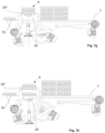
- Figs. 7a-h show a side view of a packaging device 1 for eggs in successive steps during the stacking of egg trays 20. In particular, it follows the movement of egg tray 20* during the successive steps.
- Fig. 7a shows an initial state of the packaging device 1.
- the egg tray filled with eggs 20* is brought via conveyor belt (not shown in Fig. 7 ) and a first 7a and second 7b conveyor into the receiving device 3.
- the egg tray 20* just like the "next" egg tray 20 to be stacked after egg tray 20*, is oriented with the rows 21 of eggs in the longitudinal direction or transport direction of the conveyor belt.
- the platform 25 of the lifting device 40 is located at a distance directly under the egg tray 20*.
- Egg tray 20* is located directly under stacked egg trays 9.
- the orientation of the bottom egg tray 20 of the stacked egg trays is turned 90 degrees relative to egg platform 20*.
- Fig. 7b shows the next step.
- Egg tray 20* is gripped by the platform 25 on the underside and brought upward, so that the egg tray 20* engages with the upper side on the "previous" egg tray 20, stacked one cycle earlier.
- the cups 23 of the previous egg tray are supported on the raised portions 24 of egg tray 20*.
- the front 5 and rear 6 carrier under the previous egg tray 20 can now be removed, because egg tray 20* and the egg trays stacked above that are carried by the platform 25.
- Fig. 7f the platform 25 is rotated 90 degrees relative to Fig. 7d .
- Egg tray 20* is located at the bottom and is now oriented with the rows 21 of eggs at right angles to the original orientation and so also to the transport direction.
- Egg tray 20* now has the same orientation as the egg tray 20 which in Fig. 7a was located at the bottom of the stacked egg trays 9.
- the next egg tray 20 with the rows in the transport direction can be stacked under egg tray 20*.
- Fig. 7g the carriers 5,6 are moved again to their starting position and platform 25 moves downward, wherein the carriers 5, 6 engage in raised portions 24 of egg tray 20*, so that the stacked egg trays 9 are again carried reliably.
- Fig. 7h the state of the packaging device corresponds to the state that is shown in Fig. 7a , but the stack of egg trays is now stacked one layer higher, because egg tray 20* now forms the lowest egg tray.
- the cycle can now be repeated, until the desired number of egg trays 20 is stacked.
- Each cycle of steps 7a-7g is the same, at least with regard to the movements of the lifting device.
- the transverse beams 62 remain in an open state, so that the lips 63 thereof do not engage on the lowest egg tray.
- the platform 25 still rotates of course through 90 degrees after the last egg tray is placed under the already stacked egg trays 9.
- the lifting device 4 with the stacked egg trays 9 drops downward and deposits the stacked egg trays 9 on the conveyor belt, in this case the partial conveyors 7a, 7b which supplied the last (lowest) egg tray.
- the partial conveyors transport the stacked egg trays 9 further in the transport direction under the stacking device thereof, so that a new cycle can begin.
- Figs. 8a and 8b show a schematic front view of the lifting device with stacked egg trays 9, supplying an egg tray 8, or discharging stacked egg trays 9, wherein the action of the vertical elements, in this case in the form of cams 55, blocks the passage for an egg tray 8, and keeps it open for stacked egg trays 9.
- Fig. 8a shows an egg tray 8 supplied by partial conveyors 7a, 7b.
- Cams 55 extend above the partial conveyors 7a, 7b, so that they are located in the conveyor track of the egg tray 8.
- the cams 55 block egg tray 8 because they are located in the path of respective cups 23 of the egg tray.
- the partial conveyors 7a, 7b run continuously, the egg tray 8 is stationary and then, as described above, is gripped by platform 25 and is brought upward.
- platform 25 carries the stacked egg trays 9 downward in order to deposit the stacked egg trays 9 on the partial conveyors 7a, 7b, see Fig. 8b .
- the lowest egg tray is rotated 90 degrees every time after it has engaged with the egg tray located above it, the lowest egg tray is, when deposited on the partial conveyors 7a, 7b, in another orientation than during feed of said egg tray. This is clearly visible in Fig. 8b , wherein the cams 55, which are still in the same place, are positioned just between the cups 23 of the lowest egg tray. Because the partial conveyors 7a, 7b are still running, they engage on the stacked egg trays 9 and move them in the transport direction further.
Landscapes
- Engineering & Computer Science (AREA)
- Mechanical Engineering (AREA)
- Wrapping Of Specific Fragile Articles (AREA)
Claims (16)
- Dispositif de levage (4) configuré pour le transport et le déplacement vers le haut d'un plateau à œufs carré (20) ayant une longueur de plateau et une largeur de plateau et pourvu d'un motif matriciel de plateau de coupelles (23) agencées en cinq rangées (21a-e) et six colonnes (22a-f) pour recevoir un œuf séparé dans chaque évidement, dans lequel une distance inter-centres de deux coupelles adjacentes (23) dans une rangée (21a-e) est égale à une distance inter-centres de deux coupelles adjacentes (23) dans une colonne (22a-f),le dispositif comprenant une plateforme (25) s'étendant sensiblement horizontalement avec une longueur de plateforme inférieure à une longueur et une largeur de plateforme inférieure à une largeur d'un plateau à œufs (20) qui est transporté ou au moins doit être transporté,caractérisé en ce que ladite plateforme (25) soita) sur un côté supérieur de celle-ci, est pourvue de saillies vers le haut (27) qui sont configurées pour s'engager entre les coupelles (23) du plateau à œufs sur un côté inférieur d'un plateau à œufs (20) qui est transporté ou au moins doit être transporté, où une saillie (27) a une forme de cône tronqué ou de pyramide tronquée, soitb) est pourvue de trous ayant un diamètre de plus de 17 mm s'étendant à travers la plateforme (25) ou de trous borgnes, lesdits trous s'étendant à travers la plateforme (25) ou trous borgnes étant chacun configurés pour recevoir un évidement d'un plateau à œufs (20) qui est transporté ou au moins doit être transporté,dans lequel les saillies (27), ou les trous, sont prévu(e)s selon un motif matriciel de plateforme, dans lequel les saillies (27) ou les trous sont prévu(e)s selon une partie dudit plateau à œufs (20) à transporter correspondant aux dimensions dudit motif de coupelles (23) dudit plateau à œufs à transporter, dans lequel à mi-chemin entre chaque paire de rangées adjacentes (21a-e) de saillies (27) ou de trous du motif matriciel de plateau, une rangée supplémentaire (21a-e) de saillies (27) ou de trous est prévue sur, ou dans la plateforme (25), qui est décalée par rapport à la paire de rangées adjacentes (21a-e) de la moitié de ladite distance inter-centres.
- Dispositif de levage (4) tel que revendiqué dans la revendication 1, dans lequel le dispositif de levage (4) est configuré pour faire tourner la plateforme autour d'un axe vertical.
- Dispositif de levage (4) tel que revendiqué dans la revendication 1, dans lequel les coupelles (23) du plateau à œufs reposent en utilisation entre les saillies (27) sur la plateforme (25), de préférence sur un plan à partir duquel les saillies (27) s'étendent vers le haut.
- Dispositif de levage (4) tel que revendiqué dans la revendication 1, 2 ou 3, dans lequel le périmètre de la plateforme (25) a une longueur et une largeur, chacune étant inférieure à 400 mm, dans lequel la longueur et/ou la largeur de la plateforme (25) est de préférence inférieure à 250 mm, et plus préférablement est inférieure à 220 mm.
- Dispositif de levage (4) tel que revendiqué dans une ou plusieurs des revendications précédentes, dans lequel la plateforme (25) est pourvue, sur un côté supérieur de celle-ci, de saillies dépassant vers le haut (27) ou de trous s'étendant à travers la plateforme (25) ou de trous borgnes, qui sont configuré(e)s pour pouvoir s'engager, dans deux positions tournées à 90 degrés autour d'un axe vertical, avec un côté inférieur d'un plateau à œufs (20) qui doit être transporté, et/ou dans lequel la plateforme est rectangulaire, de préférence carrée.
- Dispositif de levage (4) à saillies (27) tel que revendiqué dans une ou plusieurs des revendications précédentes, dans lequel la distance inter-centres est comprise entre 40 et 60 mm, de préférence entre 42 et 55 mm, de manière particulièrement préférée est de 48,3 mm et/ou dans lequel une saillie (27) a une surface supérieure plate qui est horizontale pendant l'utilisation.
- Dispositif de levage (4) à saillies (27) tel que revendiqué dans une ou plusieurs des revendications précédentes, dans lequel une saillie (27) a une base à partir de laquelle elle dépasse au-dessus de la plateforme (25), dans lequel la base d'une saillie (27) a un diamètre de 20 à 40 mm, de préférence de 25 à 35 mm, en particulier de 28 à 32 mm, dans lequel de préférence la base de la saillie a une forme ovale.
- Dispositif de levage (4) à saillies (27) tel que revendiqué dans la revendication 7, dans lequel une saillie (27) s'étend à partir de la base sur une hauteur, dans lequel la hauteur d'une saillie (27) est comprise entre 7,5 et 15 mm, de préférence entre 10 et 14 mm, de manière particulièrement préférée est de 13,75 mm.
- Dispositif de levage (4) à trous tel que revendiqué dans une ou plusieurs des revendications précédentes, dans lequel les trous ont une section transversale ronde, ou présentent au moins une symétrie centrale par rapport à un centre du trou respectif, et/ou dans lequel les trous ont un diamètre supérieur à 25 mm, de préférence supérieur à 30 ou 35 mm.
- Dispositif de levage (4) tel que revendiqué dans une ou plusieurs des revendications précédentes, dans lequel le dispositif de levage (4) comprend un élément de levage allongé s'étendant verticalement, agencé sur le côté inférieur de la plateforme (25).
- Combinaison du dispositif de levage (4) tel que revendiqué dans une ou plusieurs des revendications précédentes et d'un plateau à œufs (20), le plateau à œufs (20) étant sur le dispositif de levage (4) avec un motif matriciel de X rangées (21a-e) et de Y coupelles (23), dans chacune desquelles est placé un œuf, dans laquelle X est de préférence 3, 4 ou 5 et Y est de préférence 4, 5 ou 6.
- Combinaison telle que revendiquée dans la revendication 11, dans laquelle un évidement se présente sous la forme d'une dépression ayant sensiblement la forme d'une pyramide tronquée inversée ou d'un dôme inversé.
- Combinaison telle que revendiquée dans une ou plusieurs des revendications précédentes 11 et 12, dans laquelle des saillies (27) de la plateforme (25) sont en contact avec des coupelles (23) du plateau à œufs.
- Combinaison telle que revendiquée dans une ou plusieurs des revendications 11 ou 13 précédentes, dans laquelle les coupelles (23) du plateau à œufs sont supportées sur la plateforme (25) lors de l'utilisation sur une surface de base de la plateforme (25) située entre les saillies (27) de la plateforme (25), ou dans laquelle le matériau entre les coupelles (23) du plateau à œufs lors de l'utilisation est supporté sur le matériau de la plateforme (25) entre les trous.
- Dispositif de levage (4) tel que revendiqué dans une ou plusieurs des revendications 1 à 10 précédentes, dans lequel la surface de base de la plateforme (25) est plate, et de préférence s'étend horizontalement.
- Dispositif d'empilage (1) pour empiler des plateaux à œufs sensiblement carrés, le dispositif d'empilage (1) comprenant un dispositif de levage selon la revendication 1.
Applications Claiming Priority (2)
| Application Number | Priority Date | Filing Date | Title |
|---|---|---|---|
| NL2031794A NL2031794B1 (nl) | 2022-05-06 | 2022-05-06 | Hefinrichting voor eiertrays |
| PCT/NL2023/050246 WO2023214879A1 (fr) | 2022-05-06 | 2023-05-08 | Dispositif de levage pour plateaux à œufs |
Publications (3)
| Publication Number | Publication Date |
|---|---|
| EP4433397A1 EP4433397A1 (fr) | 2024-09-25 |
| EP4433397C0 EP4433397C0 (fr) | 2025-03-26 |
| EP4433397B1 true EP4433397B1 (fr) | 2025-03-26 |
Family
ID=83506390
Family Applications (1)
| Application Number | Title | Priority Date | Filing Date |
|---|---|---|---|
| EP23723674.0A Active EP4433397B1 (fr) | 2022-05-06 | 2023-05-08 | Dispositif de levage pour plateaux à oeufs |
Country Status (3)
| Country | Link |
|---|---|
| EP (1) | EP4433397B1 (fr) |
| NL (1) | NL2031794B1 (fr) |
| WO (1) | WO2023214879A1 (fr) |
Family Cites Families (2)
| Publication number | Priority date | Publication date | Assignee | Title |
|---|---|---|---|---|
| US6702272B2 (en) * | 2000-11-02 | 2004-03-09 | Airline Hydraulics Corp. | Compliant locking support fixture |
| KR101951299B1 (ko) * | 2018-08-02 | 2019-02-22 | 정광천 | 계란판 스태커 |
-
2022
- 2022-05-06 NL NL2031794A patent/NL2031794B1/nl active
-
2023
- 2023-05-08 WO PCT/NL2023/050246 patent/WO2023214879A1/fr not_active Ceased
- 2023-05-08 EP EP23723674.0A patent/EP4433397B1/fr active Active
Also Published As
| Publication number | Publication date |
|---|---|
| EP4433397C0 (fr) | 2025-03-26 |
| WO2023214879A1 (fr) | 2023-11-09 |
| NL2031794B1 (nl) | 2023-11-14 |
| EP4433397A1 (fr) | 2024-09-25 |
Similar Documents
| Publication | Publication Date | Title |
|---|---|---|
| EP2773564B1 (fr) | Dispositif pour faire avancer des tasses | |
| EP4520689A2 (fr) | Conteneur de stockage pour système automatisé de stockage et de récupération | |
| EP2397428B1 (fr) | Appareil et procédé pour empiler des unités d' emballage | |
| EP2393735A1 (fr) | Système de collecte de différents produits sur une palette de capture | |
| JP2002080016A (ja) | グループ形成装置ならびにその駆動方法 | |
| US5007785A (en) | Method and apparatus for unloading stacks of trays | |
| EP4433396B1 (fr) | Dispositif d'empilage pour plateaux à oeufs | |
| EP4433397B1 (fr) | Dispositif de levage pour plateaux à oeufs | |
| JP2025063258A (ja) | 荷下ろし構成体および荷下ろしステーション、ならびに、保管コンテナからアイテムを降ろす方法 | |
| NL1010468C2 (nl) | Inrichting en werkwijze voor het automatisch stapelen van producten op een pallet. | |
| EP0755882B1 (fr) | Appareil pour le chargement et/ou le déchargement d'un conteneur rempli de paquets empilés tels que des cartons d'oeufs | |
| WO2003106316A1 (fr) | Plaque de separation profilee pour palettiseur | |
| EP2172398B1 (fr) | Dispositif d'empilement de plusieurs produits en forme de disque | |
| CA3117120A1 (fr) | Conteneur de stockage pour systeme automatise de stockage et de recuperation | |
| WO2025037984A1 (fr) | Procédé et système de transfert de casiers à œufs | |
| US5819502A (en) | Shifting apparatus for objects such as eggs | |
| JP3952151B2 (ja) | 小物品用落下シュート | |
| EP4349722A1 (fr) | Procédé et système pour placer des produits dans des boîtes | |
| KR20010024182A (ko) | 카톤적재장치 및 방법 | |
| JP3758716B2 (ja) | 円錐台形状容器の集積・段積方法 | |
| HK40118634A (en) | Storage container for automated storage and retrieval system | |
| JP2007186241A (ja) | 箱詰め装置 | |
| WO2007039511A1 (fr) | Procédé de levage de barquettes contenant des produits horticoles à partir de plateaux de transport correspondants | |
| JPH09309585A (ja) | 缶瓶類等の収納ホッパ | |
| JP2007297103A (ja) | 農産物箱詰め用の供給装置 |
Legal Events
| Date | Code | Title | Description |
|---|---|---|---|
| STAA | Information on the status of an ep patent application or granted ep patent |
Free format text: STATUS: UNKNOWN |
|
| STAA | Information on the status of an ep patent application or granted ep patent |
Free format text: STATUS: THE INTERNATIONAL PUBLICATION HAS BEEN MADE |
|
| PUAI | Public reference made under article 153(3) epc to a published international application that has entered the european phase |
Free format text: ORIGINAL CODE: 0009012 |
|
| STAA | Information on the status of an ep patent application or granted ep patent |
Free format text: STATUS: REQUEST FOR EXAMINATION WAS MADE |
|
| 17P | Request for examination filed |
Effective date: 20240617 |
|
| AK | Designated contracting states |
Kind code of ref document: A1 Designated state(s): AL AT BE BG CH CY CZ DE DK EE ES FI FR GB GR HR HU IE IS IT LI LT LU LV MC ME MK MT NL NO PL PT RO RS SE SI SK SM TR |
|
| STAA | Information on the status of an ep patent application or granted ep patent |
Free format text: STATUS: EXAMINATION IS IN PROGRESS |
|
| 17Q | First examination report despatched |
Effective date: 20241024 |
|
| GRAP | Despatch of communication of intention to grant a patent |
Free format text: ORIGINAL CODE: EPIDOSNIGR1 |
|
| STAA | Information on the status of an ep patent application or granted ep patent |
Free format text: STATUS: GRANT OF PATENT IS INTENDED |
|
| INTG | Intention to grant announced |
Effective date: 20250103 |
|
| GRAS | Grant fee paid |
Free format text: ORIGINAL CODE: EPIDOSNIGR3 |
|
| GRAA | (expected) grant |
Free format text: ORIGINAL CODE: 0009210 |
|
| STAA | Information on the status of an ep patent application or granted ep patent |
Free format text: STATUS: THE PATENT HAS BEEN GRANTED |
|
| AK | Designated contracting states |
Kind code of ref document: B1 Designated state(s): AL AT BE BG CH CY CZ DE DK EE ES FI FR GB GR HR HU IE IS IT LI LT LU LV MC ME MK MT NL NO PL PT RO RS SE SI SK SM TR |
|
| DAV | Request for validation of the european patent (deleted) | ||
| DAX | Request for extension of the european patent (deleted) | ||
| REG | Reference to a national code |
Ref country code: GB Ref legal event code: FG4D |
|
| REG | Reference to a national code |
Ref country code: CH Ref legal event code: EP |
|
| REG | Reference to a national code |
Ref country code: DE Ref legal event code: R096 Ref document number: 602023002622 Country of ref document: DE |
|
| REG | Reference to a national code |
Ref country code: IE Ref legal event code: FG4D |
|
| U01 | Request for unitary effect filed |
Effective date: 20250425 |
|
| U07 | Unitary effect registered |
Designated state(s): AT BE BG DE DK EE FI FR IT LT LU LV MT NL PT RO SE SI Effective date: 20250512 |
|
| U20 | Renewal fee for the european patent with unitary effect paid |
Year of fee payment: 3 Effective date: 20250528 |
|
| PG25 | Lapsed in a contracting state [announced via postgrant information from national office to epo] |
Ref country code: RS Free format text: LAPSE BECAUSE OF FAILURE TO SUBMIT A TRANSLATION OF THE DESCRIPTION OR TO PAY THE FEE WITHIN THE PRESCRIBED TIME-LIMIT Effective date: 20250626 |
|
| PG25 | Lapsed in a contracting state [announced via postgrant information from national office to epo] |
Ref country code: NO Free format text: LAPSE BECAUSE OF FAILURE TO SUBMIT A TRANSLATION OF THE DESCRIPTION OR TO PAY THE FEE WITHIN THE PRESCRIBED TIME-LIMIT Effective date: 20250626 |
|
| PG25 | Lapsed in a contracting state [announced via postgrant information from national office to epo] |
Ref country code: HR Free format text: LAPSE BECAUSE OF FAILURE TO SUBMIT A TRANSLATION OF THE DESCRIPTION OR TO PAY THE FEE WITHIN THE PRESCRIBED TIME-LIMIT Effective date: 20250326 |
|
| PG25 | Lapsed in a contracting state [announced via postgrant information from national office to epo] |
Ref country code: GR Free format text: LAPSE BECAUSE OF FAILURE TO SUBMIT A TRANSLATION OF THE DESCRIPTION OR TO PAY THE FEE WITHIN THE PRESCRIBED TIME-LIMIT Effective date: 20250627 |
|
| PGFP | Annual fee paid to national office [announced via postgrant information from national office to epo] |
Ref country code: TR Payment date: 20250613 Year of fee payment: 3 |
|
| PG25 | Lapsed in a contracting state [announced via postgrant information from national office to epo] |
Ref country code: SM Free format text: LAPSE BECAUSE OF FAILURE TO SUBMIT A TRANSLATION OF THE DESCRIPTION OR TO PAY THE FEE WITHIN THE PRESCRIBED TIME-LIMIT Effective date: 20250326 |
|
| PG25 | Lapsed in a contracting state [announced via postgrant information from national office to epo] |
Ref country code: ES Free format text: LAPSE BECAUSE OF FAILURE TO SUBMIT A TRANSLATION OF THE DESCRIPTION OR TO PAY THE FEE WITHIN THE PRESCRIBED TIME-LIMIT Effective date: 20250326 |
|
| PG25 | Lapsed in a contracting state [announced via postgrant information from national office to epo] |
Ref country code: PL Free format text: LAPSE BECAUSE OF FAILURE TO SUBMIT A TRANSLATION OF THE DESCRIPTION OR TO PAY THE FEE WITHIN THE PRESCRIBED TIME-LIMIT Effective date: 20250326 |
|
| PG25 | Lapsed in a contracting state [announced via postgrant information from national office to epo] |
Ref country code: SK Free format text: LAPSE BECAUSE OF FAILURE TO SUBMIT A TRANSLATION OF THE DESCRIPTION OR TO PAY THE FEE WITHIN THE PRESCRIBED TIME-LIMIT Effective date: 20250326 |
|
| PG25 | Lapsed in a contracting state [announced via postgrant information from national office to epo] |
Ref country code: IS Free format text: LAPSE BECAUSE OF FAILURE TO SUBMIT A TRANSLATION OF THE DESCRIPTION OR TO PAY THE FEE WITHIN THE PRESCRIBED TIME-LIMIT Effective date: 20250726 |
|
| PG25 | Lapsed in a contracting state [announced via postgrant information from national office to epo] |
Ref country code: CZ Free format text: LAPSE BECAUSE OF FAILURE TO SUBMIT A TRANSLATION OF THE DESCRIPTION OR TO PAY THE FEE WITHIN THE PRESCRIBED TIME-LIMIT Effective date: 20250326 |
|
| PG25 | Lapsed in a contracting state [announced via postgrant information from national office to epo] |
Ref country code: MC Free format text: LAPSE BECAUSE OF FAILURE TO SUBMIT A TRANSLATION OF THE DESCRIPTION OR TO PAY THE FEE WITHIN THE PRESCRIBED TIME-LIMIT Effective date: 20250326 |
|
| PLBE | No opposition filed within time limit |
Free format text: ORIGINAL CODE: 0009261 |
|
| STAA | Information on the status of an ep patent application or granted ep patent |
Free format text: STATUS: NO OPPOSITION FILED WITHIN TIME LIMIT |
|
| REG | Reference to a national code |
Ref country code: CH Ref legal event code: L10 Free format text: ST27 STATUS EVENT CODE: U-0-0-L10-L00 (AS PROVIDED BY THE NATIONAL OFFICE) Effective date: 20260211 |
|
| 26N | No opposition filed |
Effective date: 20260105 |
|
| PG25 | Lapsed in a contracting state [announced via postgrant information from national office to epo] |
Ref country code: IE Free format text: LAPSE BECAUSE OF NON-PAYMENT OF DUE FEES Effective date: 20250508 |