EP4428283A1 - Lasermaschine zur behandlung von textilien - Google Patents
Lasermaschine zur behandlung von textilien Download PDFInfo
- Publication number
- EP4428283A1 EP4428283A1 EP23382219.6A EP23382219A EP4428283A1 EP 4428283 A1 EP4428283 A1 EP 4428283A1 EP 23382219 A EP23382219 A EP 23382219A EP 4428283 A1 EP4428283 A1 EP 4428283A1
- Authority
- EP
- European Patent Office
- Prior art keywords
- textile
- treated
- machine according
- laser
- image processing
- Prior art date
- Legal status (The legal status is an assumption and is not a legal conclusion. Google has not performed a legal analysis and makes no representation as to the accuracy of the status listed.)
- Withdrawn
Links
Images



Classifications
-
- D—TEXTILES; PAPER
- D06—TREATMENT OF TEXTILES OR THE LIKE; LAUNDERING; FLEXIBLE MATERIALS NOT OTHERWISE PROVIDED FOR
- D06B—TREATING TEXTILE MATERIALS USING LIQUIDS, GASES OR VAPOURS
- D06B11/00—Treatment of selected parts of textile materials, e.g. partial dyeing
- D06B11/0093—Treatments carried out during or after a regular application of treating materials, in order to get differentiated effects on the textile material
- D06B11/0096—Treatments carried out during or after a regular application of treating materials, in order to get differentiated effects on the textile material to get a faded look
-
- D—TEXTILES; PAPER
- D06—TREATMENT OF TEXTILES OR THE LIKE; LAUNDERING; FLEXIBLE MATERIALS NOT OTHERWISE PROVIDED FOR
- D06B—TREATING TEXTILE MATERIALS USING LIQUIDS, GASES OR VAPOURS
- D06B11/00—Treatment of selected parts of textile materials, e.g. partial dyeing
- D06B11/0093—Treatments carried out during or after a regular application of treating materials, in order to get differentiated effects on the textile material
-
- D—TEXTILES; PAPER
- D06—TREATMENT OF TEXTILES OR THE LIKE; LAUNDERING; FLEXIBLE MATERIALS NOT OTHERWISE PROVIDED FOR
- D06P—DYEING OR PRINTING TEXTILES; DYEING LEATHER, FURS OR SOLID MACROMOLECULAR SUBSTANCES IN ANY FORM
- D06P5/00—Other features in dyeing or printing textiles, or dyeing leather, furs, or solid macromolecular substances in any form
- D06P5/20—Physical treatments affecting dyeing, e.g. ultrasonic or electric
- D06P5/2005—Treatments with alpha, beta, gamma or other rays, e.g. stimulated rays
Definitions
- the present invention relates to a laser machine for treating textiles, whether cloth and/or garments.
- Said machines comprise a surface for placing the textile to be treated and a laser device placed above and with the capacity to mark the surface.
- the textile to be marked is placed on the surface and, subsequently, the laser device causes the laser to strike the garment, such that the laser produces a marked and/or bleached and/or worn and/or burnt and/or cut effect, obtained depending on the material of the garment, the power of the laser and the time of exposure to the laser. Therefore, the textile must be placed correctly since, otherwise, the laser will not strike it in the right areas.
- the present invention discloses a machine for treating textiles which comprises a placement surface for a textile to be treated, a laser device arranged for marking over said surface and a control device for said laser device.
- Said laser device comprises a series of stored instructions corresponding to the path to be followed by the laser for the textile to be treated.
- the machine further comprises at least one camera arranged so as to take an image of the placement surface and an image processing module.
- Said module is configured to identify the textile to be treated on said surface and its size, and to calculate the position and angle of said textile with respect to a stored position of said textile.
- Said module is connected to the control device, in such a way that the control device is configured to modify the series of instructions on the basis of the aforementioned position and angle data determined by said module.
- the presence of at least one camera arranged so as to take an image of the placement surface together with an image processing module make it possible to recognize the garment to be marked by the laser. Said recognition is performed, for example, by means of image recognition software, which identifies the model of textile to be marked and its size. For each model and/or size, the machine has a database or memory containing reference marking instructions which it accesses after identifying the garment. This means that the laser can mark different garments on the same production line without the need for the user to change the parameters, or the type of specific marking of each garment.
- the machine carries out the appropriate instructions for each garment automatically, therefore allowing a mix of garments to be supplied to the machine, without having to adjust the parameters for each garment or work with sets of identical garments in order to avoid having to change said parameters frequently.
- the machine also detects the position of the garment and, on the basis of this position, changes the reference instructions for the laser, so that the marking is adapted to the position detected. This feature also helps to automate the marking process and in particular facilitates or speeds up the process of placing the garment, which does not need to be placed so precisely to obtain the desired marking.
- the machine comprises means for measuring the focal distance.
- the focal distance means the distance between the laser device and the work surface. Knowing the exact focal distance is advantageous when working or making marks with a laser, since this makes it possible to better focus the energy of the laser on the points necessary.
- the means for measuring the focal distance comprise said at least one camera and the image processing module.
- the ability to measure the focal distance using the camera which captures the image and the image processing module, makes it possible to perform the necessary operations to make the mark with the laser without the need to add more elements to the machine.
- the measuring means comprise a laser distance sensor.
- Having a laser distance sensor makes it possible to determine with great precision the focal distance, or any other distance which it is necessary to determine in the marking process.
- the use of said laser sensor may also serve as a method for checking or confirming the distance measured by means of other sensors or the at least one camera.
- the image processing module identifies the textile to be treated using image recognition.
- the ability to identify the garment to be marked, by means of image recognition software, means that it is not necessary to depend on the visibility of any code, or other identification element, on the surface of said garment. It is thus possible to determine all the necessary information regarding the garment by means of the hardware already present in the machine, and the analysis, using the image processing module, of what is captured by the at least one camera.
- the image recognition is performed on the basis of artificial intelligence algorithms.
- Identifying the garment by recognition of the garment through an image by means of artificial intelligence helps obtain control over production, the treatment process and quality control that is more versatile. This can be achieved using neural network structures, feeding the latter with databases of images, various examples and information and thus providing them with prior training, such that they can learn to identify the various textiles in any kind of situation. As the volume of examples and production increases, the better and more versatile the identification of any type of textile becomes, and the same applies to the subsequent quality control. In addition, all this learning can be used, in turn, to feed into and improve various artificial intelligence models and algorithms for use in Industry 4.0.
- the image recognition is performed on the basis of identification and calculation of parameters and physical characteristics of the garment.
- the image processing module may extract certain parameters that facilitate identification of the textile. Some of the parameters may be, for example, the length or width of the textile, the ratio between said length and said height, angles between lines of intersection of the textile, the presence of elements, such as buttons or seams, etc.
- the identification and calculation of these parameters may also help to position and orient the garment in relation to its reference coordinate centre and axes of the machine. The calculation of these parameters facilitates identification of the garment.
- the capacity of the image processing module to calculate these parameters, or any other parameter necessary, also makes it possible to take various measurements that can be applied to various functions for production, such as quality control of the textiles or as described above, correct positioning thereof for marking.
- the image processing module identifies the surface of the textile to be treated.
- the machine through the image processing module, is able to identify which surface of the textile is facing the laser. This makes it possible to identify, for example, if the textile is face up or face down, and therefore if the surface to be treated is the front or back of the textile.
- This feature is advantageous would be in the treatment of trousers, as it can identify which leg, left or right, is facing the laser and which part, front or back. Depending on the reference provided, it is even possible to make this distinction with the trousers folded in half lengthwise.
- the machine performs quality control after treatment by means of the image processing module.
- the image processing module it is possible to determine whether the end result of the treatment complies with the quality parameters established.
- This process speeds up production and allows fast and rapid dual quality control, on the one hand by the machine after treatment and on the other hand by the operator.
- This quality control can be performed, for example, by comparing the final image obtained with a stored reference image.
- OCR optical character recognition
- the machine identifies the size of the textile to be treated and adjusts the treatment to said size.
- control module identifies the textile to be treated by automatic identification and data capture (AIDC), such as optical character recognition (OCR).
- AIDC automatic identification and data capture
- OCR optical character recognition
- the machine comprises an illumination system for illuminating the placement surface for the garments to be treated.
- the camera In order for the camera to have an optimal view of the textile, it is advantageous to have a system for illuminating the surface on which the garments are placed.
- the camera can capture the clearest image possible, and illumination can be controlled on the textiles and on the surface, achieving illumination which is uniform and constant over time. This facilitates and simplifies image recognition by the image processing module.
- having good illumination also makes it possible for the operator to see, just by looking, any flaws on the placement surface or on the actual garment when placed.
- the machine comprises a system for 3D scanning of the textile.
- Another possible application is the ability to measure the distance from the laser at any point on the textile, making it possible to correct the laser control instructions suitably for more precise marking, which in turn can greatly facilitate the marking of any textile with a clearly three-dimensional surface, such as a cap, hat or footwear.
- the machine comprises at least two cameras with different optics.
- Having more than one camera with different optics makes it possible to capture the textile from different points of view, which is advantageous with a view to performing better analysis of the image and identifying the garment more accurately.
- having different optics also helps to obtain stronger or weaker focus and/or detail of the image, which can be useful with a view to performing more or less rapid calculations for cases in which stronger or weaker resolution or precision is required, adapting said parameters to production needs.
- Figure 1 shows a laser machine 1 for treating textiles according to the present invention.
- the machine 1 comprises a laser device 100, a surface 20 for the placement of textiles and a user interface 30.
- the laser device 100 in turn comprises a control device 50 and a scanning head 105.
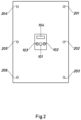
- Figure 2 shows the internal surface of the roof of the machine 1, viewed from the surface 20. in this figure, other components of the machine 1 can be seen. More particularly, it shows an opening 101 through which the laser beam exits. Said laser beam is modulated and controlled by the scanning head 105, which is in turn controlled by the control device 50 of the laser. Said control device 50 has the task of modifying the direction, focus and/or power of the laser as required for each mark by actuating the relevant elements, such as mirrors and lenses, to redirect and focus the laser.
- This figure also shows two cameras 102 and 103, which have the task of capturing the image of the textile placed on the surface 20. Said two cameras 102 and 103 may be used individually or together.
- FIG. 2 also shows an illumination system 200 which comprises a set of lights 201, 202, 203, 204, 205 and 206 for appropriate illumination of the work surface where the textiles are placed and the textile itself, in such a way as to aid optimum capture of images by the cameras 102 and 103.
- an illumination system 200 which comprises a set of lights 201, 202, 203, 204, 205 and 206 for appropriate illumination of the work surface where the textiles are placed and the textile itself, in such a way as to aid optimum capture of images by the cameras 102 and 103.
- a 3D scanning system 104 Said system makes it possible to capture the textile in three dimensions, such that the laser device can determine the distance to all points on the surface of the textile to be marked, allowing it to adjust the marking instructions accordingly, or detect unwanted wrinkles or positions of the textile which are incorrect for good marking.
- Figure 3 shows the machine 1 in front elevation, making it possible to delimit a focal distance f between the laser device 100, more specifically the opening 101, and the surface 20 where the textiles are placed. It also shows the scanning head 105 of the laser 100, from the front and, in profile, the user interface 30 and the control device 50.
- Figure 4a shows an example of the capture and analysis of an image of a textile by the image processing module.
- Said figure depicts a textile 40 which is captured by at least one camera 102 or 103.
- Said at least one camera 102 or 103 sends information, as a digital image, to the image processing module.
- Said module interprets the image, in such a way as to allow identification of the outline of the textile, which in turn makes it possible to frame the textile 40 in a rectangle 41 delimiting said textile 40, said rectangle 41 having a coordinate centre d 1 of said textile.
- Said coordinate centre d 1 is positioned at a point (x 1 ,y 1 ) of a reference coordinate centre 0 and axes (X,Y) of the machine.
- the image processing module calculates appropriate correction factors to modify the instructions to be received by the control device in such a way that marking is matched to the actual position and orientation of the textile.
- Figure 4b shows an example of the capture and analysis of an image of a textile in which the image processing module is capable of detecting, for the same model and size of textile 40, the surface to be marked.
- the top drawing shows an image captured by one of the cameras 102 or 103 of a type and model of textile, in which the visible surface is the front part of the right leg of a pair of trousers, whereas, in the bottom drawing, the visible surface, and therefore the surface captured by one of the cameras 102 or 103, is the front part of the left leg of the pair of trousers.
- the module will delimit the textile 40 using a rectangle 41 and will determine a coordinate centre d 2 and axes (d x2 ,d y2 ) relating to said textile and a centre d 3 and axes (d x3 ,d y3 ) respectively for each surface of the textile captured.
- the image processing module will analyse and identify this surface, for which purpose it will access one series of saved reference instructions or another according to the surface identified by the image processing module. Subsequently, said series of reference instructions will be modified to adapt the marking to the actual position and orientation of the textile.
- Figure 5 shows some of the key parameters which make it possible to identify the type, model and size of a textile 40 captured by one of the cameras 102 or 103.
- the image processing module of the image captured, it is possible to extract certain parameters which facilitate the identification of the textile.
- some of these parameters may be, for example, the width p of the leg at the hem, the length I of the trousers, the width c of the waist, the crotch depth t or distance between the crotch and the waist.
- the calculation of these parameters also helps to position and orient the garment in relation to the reference coordinate centre 0 and axes (X,Y) of the machine, and therefore an angle ⁇ of orientation of the garment can in turn also be obtained.
- the calculation of these parameters facilitates identification of the garment.
- the capacity of the image processing module to calculate these parameters, or any other parameter necessary, also makes it possible to take various measurements that can be applied to various functions for production, such as quality control of the textiles or as described above, correct positioning thereof for marking.
- Figure 6a shows an example of obtaining a 3D map 42 of a garment 40.
- a 3D map 42 of topographical type is obtained, in which each point on the surface of the textile 40 is represented by a colour or value, depending on the distance to the height at which it is located with respect to the surface 20 where the textile 40 is situated.
- This type of 3D map is advantageous for various applications such as identifying the textile to be marked, detecting unwanted wrinkles, detecting the position and orientation of the textile, quality control of the textile, or even recalibrating the power or incision of the laser according to the actual distance of each point with respect to said laser.
- Figure 6b shows another example of obtaining a 3D map 42 of the same garment 40. in this case, said figure shows how said 3D map may be used for detecting wrinkles and incorrect positioning of the textile 40.
- FIG. 7 shows a schematic diagram of the interaction between various elements of an embodiment of a machine for treating textiles. Said diagram shows the communication and exchange of information between said elements making it possible to achieve the operation of the machine described above.
- Optical sensors 1100 such as a camera 102 or 103, capture images, and have the task of sending this information to a first processing unit 31 of programmable type (FGPA) and/or to another graphics processing unit 32 (GPU).
- the two units 31 and 32 are also connected such that they can work together, if necessary, when obtaining and computing the information received by the sensors 1100.
- the graphics processing unit 32 (GPU) is also connected to a first central processing unit 33 (CPU) which has the task of coordinating and processing the image information.
- CPU central processing unit
- this first central processing unit 33 is connected to a second central processing unit 51 (CPU), such that they can exchange information and send orders to one another when required.
- the unit 51 is also in turn in communication with a digital signal processor 52 (DSP), which in turn is connected to a second processing unit 53 of programmable type (FGPA).
- DSP digital signal processor
- FGPA programmable type
- the digital signal processor 52 and the unit 53 have the task of interpreting the instructions in the form of a digital signal from the unit 51 and translating same into instructions suitable for controllers, sensors or actuators.
- the processor 52 has the task of performing the calculations to give the necessary orders to the second unit 53, which in turn translates and sends said orders as control parameters for the various devices to which it is connected.
- Said second unit 53 is connected to a programmable logic controller 54 (PLC), which has the task of general mechanical control of the machine 1, to the scanning head 105, to the laser 100 and to sensors and/or actuators 110, such as safety sensors of the type which stop or restart operation of the machine automatically.
- PLC programmable logic controller 54
Landscapes
- Engineering & Computer Science (AREA)
- Textile Engineering (AREA)
- Chemical & Material Sciences (AREA)
- Materials Engineering (AREA)
- Treatment Of Fiber Materials (AREA)
Priority Applications (2)
| Application Number | Priority Date | Filing Date | Title |
|---|---|---|---|
| EP23382219.6A EP4428283A1 (de) | 2023-03-08 | 2023-03-08 | Lasermaschine zur behandlung von textilien |
| PCT/ES2024/070133 WO2024184567A1 (es) | 2023-03-08 | 2024-03-05 | Máquina láser de tratamiento de textiles |
Applications Claiming Priority (1)
| Application Number | Priority Date | Filing Date | Title |
|---|---|---|---|
| EP23382219.6A EP4428283A1 (de) | 2023-03-08 | 2023-03-08 | Lasermaschine zur behandlung von textilien |
Publications (1)
| Publication Number | Publication Date |
|---|---|
| EP4428283A1 true EP4428283A1 (de) | 2024-09-11 |
Family
ID=85781702
Family Applications (1)
| Application Number | Title | Priority Date | Filing Date |
|---|---|---|---|
| EP23382219.6A Withdrawn EP4428283A1 (de) | 2023-03-08 | 2023-03-08 | Lasermaschine zur behandlung von textilien |
Country Status (2)
| Country | Link |
|---|---|
| EP (1) | EP4428283A1 (de) |
| WO (1) | WO2024184567A1 (de) |
Citations (4)
| Publication number | Priority date | Publication date | Assignee | Title |
|---|---|---|---|---|
| WO1997049062A1 (en) * | 1996-06-18 | 1997-12-24 | Levi Strauss & Co. | Method and apparatus for the optical determination of the orientation of a garment workpiece |
| US6090158A (en) * | 1998-09-08 | 2000-07-18 | Levi Strauss & Co. | Localized finishing of garment workpieces |
| WO2001025824A2 (en) * | 1999-10-05 | 2001-04-12 | Technolines, Llc | A scanned modulated laser for processing material surfaces |
| EP3561489A1 (de) * | 2018-04-27 | 2019-10-30 | Jeanología, S.L. | System und verfahren zur charakterisierung von auf einem gewebe markierten mustern |
-
2023
- 2023-03-08 EP EP23382219.6A patent/EP4428283A1/de not_active Withdrawn
-
2024
- 2024-03-05 WO PCT/ES2024/070133 patent/WO2024184567A1/es not_active Ceased
Patent Citations (5)
| Publication number | Priority date | Publication date | Assignee | Title |
|---|---|---|---|---|
| WO1997049062A1 (en) * | 1996-06-18 | 1997-12-24 | Levi Strauss & Co. | Method and apparatus for the optical determination of the orientation of a garment workpiece |
| US5790687A (en) * | 1996-06-18 | 1998-08-04 | Levi Strauss & Co. | Method and apparatus for the optical determination of the orientation of a garment workpiece |
| US6090158A (en) * | 1998-09-08 | 2000-07-18 | Levi Strauss & Co. | Localized finishing of garment workpieces |
| WO2001025824A2 (en) * | 1999-10-05 | 2001-04-12 | Technolines, Llc | A scanned modulated laser for processing material surfaces |
| EP3561489A1 (de) * | 2018-04-27 | 2019-10-30 | Jeanología, S.L. | System und verfahren zur charakterisierung von auf einem gewebe markierten mustern |
Also Published As
| Publication number | Publication date |
|---|---|
| WO2024184567A1 (es) | 2024-09-12 |
Similar Documents
| Publication | Publication Date | Title |
|---|---|---|
| US4901359A (en) | Method and apparatus for automatically cutting material in standard patterns | |
| KR100816602B1 (ko) | 사칭 검출 장치 및 사칭 검출 방법 | |
| CN108898634B (zh) | 基于双目相机视差对绣花机目标针眼进行精确定位的方法 | |
| CN101274432B (zh) | 目标物取出装置 | |
| US20180194008A1 (en) | Calibration device, calibration method, and computer readable medium for visual sensor | |
| JP2012215394A (ja) | 三次元計測装置および三次元計測方法 | |
| JP4792521B2 (ja) | 布製品識別装置および布製品把持システム | |
| WO2004011876A1 (en) | Apparatus and method for automatically arranging three dimensional scan data using optical marker | |
| JP5584832B2 (ja) | 円柱状物体の直径測定装置及び測定方法、測定プログラム | |
| US10223577B2 (en) | Face image processing apparatus | |
| KR20170068071A (ko) | 형상측정장치와 이를 이용한 형상측정방법 | |
| KR100502560B1 (ko) | 광학식 마커를 이용한 3차원 측정 데이터 자동 정렬장치및 그 방법 | |
| JP2025530115A (ja) | 生地の縫製およびしわ伸ばしのためのシステムおよび方法 | |
| ITUB20155547A1 (it) | Procedimento per la calibrazione di un sistema combinato di taglio e incisione laser e di ricamo e un relativo sistema combinato di taglio e incisione laser e di ricamo | |
| CN107979983A (zh) | 用于确定眼睛的位置和/或取向的方法和设备 | |
| JP2017173142A (ja) | 画像処理装置、画像処理方法およびミクロジョイント切断システム | |
| KR102597704B1 (ko) | 의류 원단 핸들링 자동화 장치 및 방법 | |
| WO2024184567A1 (es) | Máquina láser de tratamiento de textiles | |
| CN115516274B (zh) | 用于测量对象物的位置以及姿势的标记、装置、系统以及测量方法 | |
| CN119998622A (zh) | 包括边缘识别装置的用于对金属板材或金属片材进行加工和/或移动的机器和方法 | |
| JP2017007026A (ja) | 位置補正システム | |
| JPH03268818A (ja) | 折曲機の角度計測装置 | |
| JP2014182115A (ja) | 三次元計測装置、制御方法、プログラム、及び記憶媒体 | |
| MXPA05010335A (es) | Metodo para inspeccionar los criterios de calidad de estructuras textiles planas incorporadas en una forma de varias capas segun un contorno. | |
| CN117222862A (zh) | 衣物的汽蒸定形机及汽蒸定形方法 |
Legal Events
| Date | Code | Title | Description |
|---|---|---|---|
| PUAI | Public reference made under article 153(3) epc to a published international application that has entered the european phase |
Free format text: ORIGINAL CODE: 0009012 |
|
| STAA | Information on the status of an ep patent application or granted ep patent |
Free format text: STATUS: THE APPLICATION HAS BEEN PUBLISHED |
|
| AK | Designated contracting states |
Kind code of ref document: A1 Designated state(s): AL AT BE BG CH CY CZ DE DK EE ES FI FR GB GR HR HU IE IS IT LI LT LU LV MC ME MK MT NL NO PL PT RO RS SE SI SK SM TR |
|
| STAA | Information on the status of an ep patent application or granted ep patent |
Free format text: STATUS: REQUEST FOR EXAMINATION WAS MADE |
|
| P01 | Opt-out of the competence of the unified patent court (upc) registered |
Free format text: CASE NUMBER: APP_51481/2024 Effective date: 20240912 |
|
| 17P | Request for examination filed |
Effective date: 20240926 |
|
| RBV | Designated contracting states (corrected) |
Designated state(s): AL AT BE BG CH CY CZ DE DK EE ES FI FR GB GR HR HU IE IS IT LI LT LU LV MC ME MK MT NL NO PL PT RO RS SE SI SK SM TR |
|
| STAA | Information on the status of an ep patent application or granted ep patent |
Free format text: STATUS: EXAMINATION IS IN PROGRESS |
|
| 17Q | First examination report despatched |
Effective date: 20250801 |
|
| STAA | Information on the status of an ep patent application or granted ep patent |
Free format text: STATUS: THE APPLICATION IS DEEMED TO BE WITHDRAWN |
|
| 18D | Application deemed to be withdrawn |
Effective date: 20251202 |