EP4427631A1 - Schiebestruktur, montageverfahren und aktuator - Google Patents
Schiebestruktur, montageverfahren und aktuator Download PDFInfo
- Publication number
- EP4427631A1 EP4427631A1 EP22894223.1A EP22894223A EP4427631A1 EP 4427631 A1 EP4427631 A1 EP 4427631A1 EP 22894223 A EP22894223 A EP 22894223A EP 4427631 A1 EP4427631 A1 EP 4427631A1
- Authority
- EP
- European Patent Office
- Prior art keywords
- pipe body
- sliding part
- sliding
- wall
- structure according
- Prior art date
- Legal status (The legal status is an assumption and is not a legal conclusion. Google has not performed a legal analysis and makes no representation as to the accuracy of the status listed.)
- Pending
Links
Images






Classifications
-
- F—MECHANICAL ENGINEERING; LIGHTING; HEATING; WEAPONS; BLASTING
- F16—ENGINEERING ELEMENTS AND UNITS; GENERAL MEASURES FOR PRODUCING AND MAINTAINING EFFECTIVE FUNCTIONING OF MACHINES OR INSTALLATIONS; THERMAL INSULATION IN GENERAL
- F16B—DEVICES FOR FASTENING OR SECURING CONSTRUCTIONAL ELEMENTS OR MACHINE PARTS TOGETHER, e.g. NAILS, BOLTS, CIRCLIPS, CLAMPS, CLIPS OR WEDGES; JOINTS OR JOINTING
- F16B7/00—Connections of rods or tubes, e.g. of non-circular section, mutually, including resilient connections
- F16B7/10—Telescoping systems
- F16B7/105—Telescoping systems locking in discrete positions, e.g. in extreme extended position
-
- A—HUMAN NECESSITIES
- A47—FURNITURE; DOMESTIC ARTICLES OR APPLIANCES; COFFEE MILLS; SPICE MILLS; SUCTION CLEANERS IN GENERAL
- A47B—TABLES; DESKS; OFFICE FURNITURE; CABINETS; DRAWERS; GENERAL DETAILS OF FURNITURE
- A47B9/00—Tables with tops of variable height
- A47B9/20—Telescopic guides
-
- A—HUMAN NECESSITIES
- A47—FURNITURE; DOMESTIC ARTICLES OR APPLIANCES; COFFEE MILLS; SPICE MILLS; SUCTION CLEANERS IN GENERAL
- A47C—CHAIRS; SOFAS; BEDS
- A47C19/00—Bedsteads
- A47C19/02—Parts or details of bedsteads not fully covered in a single one of the following subgroups, e.g. bed rails, post rails
- A47C19/021—Bedstead frames
- A47C19/024—Legs
-
- A—HUMAN NECESSITIES
- A47—FURNITURE; DOMESTIC ARTICLES OR APPLIANCES; COFFEE MILLS; SPICE MILLS; SUCTION CLEANERS IN GENERAL
- A47C—CHAIRS; SOFAS; BEDS
- A47C19/00—Bedsteads
- A47C19/04—Extensible bedsteads, e.g. with adjustment of length, width, height
- A47C19/045—Extensible bedsteads, e.g. with adjustment of length, width, height with entire frame height or inclination adjustments
-
- A—HUMAN NECESSITIES
- A47—FURNITURE; DOMESTIC ARTICLES OR APPLIANCES; COFFEE MILLS; SPICE MILLS; SUCTION CLEANERS IN GENERAL
- A47C—CHAIRS; SOFAS; BEDS
- A47C3/00—Chairs characterised by structural features; Chairs or stools with rotatable or vertically-adjustable seats
- A47C3/20—Chairs or stools with vertically-adjustable seats
- A47C3/24—Chairs or stools with vertically-adjustable seats with vertical spindle
-
- A—HUMAN NECESSITIES
- A47—FURNITURE; DOMESTIC ARTICLES OR APPLIANCES; COFFEE MILLS; SPICE MILLS; SUCTION CLEANERS IN GENERAL
- A47C—CHAIRS; SOFAS; BEDS
- A47C3/00—Chairs characterised by structural features; Chairs or stools with rotatable or vertically-adjustable seats
- A47C3/20—Chairs or stools with vertically-adjustable seats
- A47C3/40—Telescopic guides
-
- F—MECHANICAL ENGINEERING; LIGHTING; HEATING; WEAPONS; BLASTING
- F16—ENGINEERING ELEMENTS AND UNITS; GENERAL MEASURES FOR PRODUCING AND MAINTAINING EFFECTIVE FUNCTIONING OF MACHINES OR INSTALLATIONS; THERMAL INSULATION IN GENERAL
- F16H—GEARING
- F16H25/00—Gearings comprising primarily only cams, cam-followers and screw-and-nut mechanisms
- F16H25/18—Gearings comprising primarily only cams, cam-followers and screw-and-nut mechanisms for conveying or interconverting oscillating or reciprocating motions
- F16H25/20—Screw mechanisms
-
- F—MECHANICAL ENGINEERING; LIGHTING; HEATING; WEAPONS; BLASTING
- F16—ENGINEERING ELEMENTS AND UNITS; GENERAL MEASURES FOR PRODUCING AND MAINTAINING EFFECTIVE FUNCTIONING OF MACHINES OR INSTALLATIONS; THERMAL INSULATION IN GENERAL
- F16M—FRAMES, CASINGS OR BEDS OF ENGINES, MACHINES OR APPARATUS, NOT SPECIFIC TO ENGINES, MACHINES OR APPARATUS PROVIDED FOR ELSEWHERE; STANDS; SUPPORTS
- F16M11/00—Stands or trestles as supports for apparatus or articles placed thereon ; Stands for scientific apparatus such as gravitational force meters
- F16M11/20—Undercarriages with or without wheels
- F16M11/24—Undercarriages with or without wheels changeable in height or length of legs, also for transport only, e.g. by means of tubes screwed into each other
- F16M11/26—Undercarriages with or without wheels changeable in height or length of legs, also for transport only, e.g. by means of tubes screwed into each other by telescoping, with or without folding
-
- A—HUMAN NECESSITIES
- A47—FURNITURE; DOMESTIC ARTICLES OR APPLIANCES; COFFEE MILLS; SPICE MILLS; SUCTION CLEANERS IN GENERAL
- A47B—TABLES; DESKS; OFFICE FURNITURE; CABINETS; DRAWERS; GENERAL DETAILS OF FURNITURE
- A47B9/00—Tables with tops of variable height
- A47B9/04—Tables with tops of variable height with vertical spindle
-
- F—MECHANICAL ENGINEERING; LIGHTING; HEATING; WEAPONS; BLASTING
- F16—ENGINEERING ELEMENTS AND UNITS; GENERAL MEASURES FOR PRODUCING AND MAINTAINING EFFECTIVE FUNCTIONING OF MACHINES OR INSTALLATIONS; THERMAL INSULATION IN GENERAL
- F16H—GEARING
- F16H25/00—Gearings comprising primarily only cams, cam-followers and screw-and-nut mechanisms
- F16H25/18—Gearings comprising primarily only cams, cam-followers and screw-and-nut mechanisms for conveying or interconverting oscillating or reciprocating motions
- F16H25/20—Screw mechanisms
- F16H2025/2062—Arrangements for driving the actuator
- F16H2025/2075—Coaxial drive motors
- F16H2025/2078—Coaxial drive motors the rotor being integrated with the nut or screw body
-
- F—MECHANICAL ENGINEERING; LIGHTING; HEATING; WEAPONS; BLASTING
- F16—ENGINEERING ELEMENTS AND UNITS; GENERAL MEASURES FOR PRODUCING AND MAINTAINING EFFECTIVE FUNCTIONING OF MACHINES OR INSTALLATIONS; THERMAL INSULATION IN GENERAL
- F16H—GEARING
- F16H25/00—Gearings comprising primarily only cams, cam-followers and screw-and-nut mechanisms
- F16H25/18—Gearings comprising primarily only cams, cam-followers and screw-and-nut mechanisms for conveying or interconverting oscillating or reciprocating motions
- F16H25/20—Screw mechanisms
- F16H2025/2062—Arrangements for driving the actuator
- F16H2025/2084—Perpendicular arrangement of drive motor to screw axis
Definitions
- the present invention relates to the technical field of sliding structures, particularly to a sliding structure, a mounting method, and an actuator.
- Actuators are widely used in furniture or electrical appliances with adjustable positions, such as beds, chairs and tables.
- the main function of actuators is to drive a target object to adjust its position, and its movement is intuitively represented as the linear reciprocating movement on the part of retractable pipe fittings.
- Sliding structures such as sliders, sliding blades, sliding sleeves are usually disposed between the relatively moving pipes fittings to support components, reduce friction and eliminate clearance.
- holes are usually processed on side walls of the pipe fittings, and parts of the sliding structures are embedded in the holes.
- the present invention aims at solving at least one of the technical problems existing in the prior art.
- the present invention proposes a sliding structure, a mounting method, and an actuator, where the sliding structure has the advantages of removing the technological grooves which are disposed on the inner and outer pipe walls to assist mounting, firmly clamping the sliding part on the relatively retractable pipe fittings to prevent the sliding part from easily coming out or being pulled out, and at the same time improving the mounting speed and convenience.
- the sliding structure includes a first pipe body; a second pipe body slidable disposed inside the first pipe body; a second sliding part, one side of which is clamped on an outer wall of the second pipe body, and the other side of which is slidable connected to an inner wall of the first pipe body; a first sliding part, a part of which extends beyond the end of the second pipe body when not mounted into the first pipe body, and which is directly clamped on the second pipe body or indirectly clamped on the second pipe body by the second sliding part; when mounted into the first pipe body, the first sliding part is detached from the end of the second pipe body, one side of the first sliding part clamped on the inner wall of the first pipe body, and the other side of the first sliding part slidable connected to the outer wall of the second pipe body.
- the present invention has the beneficial effects that the pocket holes required for mounting the first sliding part are reduced in quantity, which reduces the production cost, improves the service strength of the pipe wall, and avoid the deformation of the pipe wall; by directly or indirectly clamping the first sliding part on the second pipe body, part of the first sliding part extends beyond the end of the second pipe body; no additional positioning tool is required to fix the first sliding part, thus reducing the cost and improving the assembly efficiency.
- the first sliding part includes a connecting part, which is disposed between the second pipe body and the first pipe body; a flange edge, which is disposed at one end of the connecting part, and abuts against an end face of the first pipe body; and multiple first sliders, which are arranged between the second pipe body and the first pipe body, and are connected to the other end of the connecting part.
- an end of the outer wall of the second pipe body is equipped with multiple second slotted holes, and the second sliding part includes second bosses which areclamped in the multiple second slotted holes; and second sliders which are connected to the second bosses, and are slidable connected to the first pipe body.
- the first sliding part when not mounted into the first pipe body, the first sliding part is directly clamped on the second pipe body, the first sliding part is inclined towards the inner side of the second pipe body, and each first slider extends beyond the end of the second pipe body, and the first sliding part is clamped on the end of the second pipe body.
- a clamping part is disposed between each first slider and the connecting part to face towards the second pipe body.
- the clamping part is clamped against the end of the second pipe body.
- the clamping part is a transition surface, one end of which is connected to the first slider, and the other end of which is connected to the connecting part.
- the first sliding part when not mounted into the first pipe body, the first sliding part is indirectly clamped on the second pipe body, the first sliding part is clamped with the second sliding part, and the first sliding part extends beyond the end of the second pipe body.
- the second sliding part is equipped with a clamping tooth
- the first sliding part is equipped with a bayonet matching the clamping tooth
- the clamping tooth is clamped with the bayonet
- the bayonet includes a stop wall and an escape wall, which are connected to each other, the stop wall is located at a side of the bayonet close to the flange edge, an acute angle is formed between the stop wall and the escape wall, and the clamping tooth is a rod-shaped protrusion inclined towards the bayonet.
- a sliding gap exists between the second pipe body and the first pipe body, a thickness of the connecting part is less than a dimension of the sliding gap, and a thickness of the first sliding part is more than or equal to the dimension of the sliding gap.
- a sliding gap exists between the second pipe body and the first pipe body, interference fit is realized between the first slider and the sliding gap, and clearance fit is realized between the connecting part and the second pipe body.
- a first boss is disposed on a side of the first slider facing towards the first pipe body, and multiple first slotted holes for accommodating the first bosses are disposed on an end of the inner wall of the first pipe body.
- a gap exists between the first boss and the inner wall opposite to the first boss of the first pipe body.
- the first slotted holes do not penetrate the inner wall of the first pipe body.
- a side of each first slotted hole facing away from the flange edge is provided with a chamfered surface, and a side of the first slotted hole close to the flange edge abuts against the first boss.
- a side of the first boss facing away from the flange edge has a guide slope, and the guide slope is configured for guiding the first pipe body when the first sliding part is not mounted into the first pipe body.
- multiple the first sliders is arranged along a circumferential direction of the second pipe body.
- multiple the second sliders is arranged along a circumferential direction of the second pipe body.
- the first sliding part is an annular structure, an unclosed C-shaped annular structure, or is formed by splicing two opposite half rings.
- a mounting method includes the following steps: step 1, vertically placing the second pipe body on an operating platform, so that an end of the second pipe body equipped with second slotted holes faces upwards; step 2, sleeving the first sliding part on the second pipe body from top to bottom, so that the clamping part abuts against an upper end of the second pipe body, and meanwhile the first sliders are inclined towards an inside of the second pipe body, so that the first sliding part is clamped on the end of the second pipe body; step 3, placing the second sliding part inside the second slotted holes; step 4: sleeving the first pipe body on an outer surface of the first slider from top to bottom, and a lower end of the first pipe body abuts against the flange edge during the downward movement of the first pipe body and drives the first sliding part to move downwards, so that the first sliding part enters the gap between the first pipe body and the second pipe body, and meanwhile the first bosses snap into the first slotted holes.
- a mounting method of the sliding structure includes the following steps: step 1, sleeving the first sliding part on the second pipe body, and fixing the second sliding part on the second pipe body; step 2, moving the first sliding part until the first sliding part is engaged with the second sliding part, so that the first sliding part is fixed on the second pipe body; step 3, sleeving the first pipe body on an outer surface of the first sliding part to make the first pipe body press the first sliding part to bend and deform towards the inside of the second pipe body, so that the first pipe body is sleeved on the first sliding part conveniently; step 4: pushing the first pipe body to the second pipe body.
- An actuator including the sliding structure as described above; a box body, where a driving part is disposed inside and which is fixedly connected to one end of the sliding structure; a screw rod assembly, disposed in the sliding structure and containing a hollow transmission rod, a screw rod and a nut.
- One end of the hollow transmission rod is connected to a rotating end of the driving part; the other end of the hollow transmission rod is fixedly connected to the nut; the screw rod is disposed inside the hollow transmission rod; an outer peripheral surface of the screw rod is engaged with the nut through threads; an end of the screw rod far from the box body is connected to the other end of the sliding structure; and the driving part is configured to drive the sliding structure to perform retractable motion by the screw rod assembly.
- the end of the screw rod facing away from the box body is directly connected to a bottom plate, an outer peripheral surface of the bottom plate is fixedly connected to an inner wall of the second pipe body, and the box body is fixedly connected to the first pipe body.
- the end of the screw rod facing away from the box body is directly connected to a bottom plate, an outer peripheral surface of the bottom plate is fixedly connected to the inner wall of the first pipe body, and the box body is fixedly connected to the second pipe body.
- the sliding structure further includes a third pipe body which is slidable sleeved on the first pipe body, and structures between the third pipe body and the first pipe body is the same as those between the first pipe body and the second pipe body.
- Driving part 1 box body 2, screw rod assembly 3, second pipe body 4, first pipe body 5, first sliding part 6, second sliding part 7, second slotted hole 8, bottom plate 9, first slotted hole 10, chamfered surface 11, third pipe body 12, hollow transmission rod 31, screw rod 32, nut 33, flange edge 61, first slider 62, first boss 63, bayonet 64, clamping part 64a, connecting part 65, second slider 71, second boss 72, and clamping tooth 73.
- the terms “mounted” and “connected” should be understood in a broad sense. For example, they can be fixedly connected, dismountable connected or integrally connected; they can be mechanically connected or electrically connected; they can be directly connected or indirectly connected through an intermediate medium, or internally connected.
- the specific meanings of the above terms in the present invention can be understood according to specific situations.
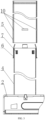
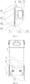
- the present invention discloses a sliding structure, which comprises a first pipe body 5, a second pipe body 4, a second sliding part 7 and a first sliding part 6, where the second pipe body 4 is slidably arranged in the first pipe body 5; one side of the second sliding part 7 is clamped on an outer wall of the second pipe body 4, and the other side of the second sliding part 7 is slidably connected with the inner wall of the first pipe body 5.
- first sliding part 6 When the first sliding part 6 is not mounted into the first pipe body 5, a part of the first sliding part 6 extends beyond the end of the second pipe body 4, and the first sliding part 6 is directly clamped on the second pipe body 4.
- first sliding part 6 When the first sliding part 6 is mounted into the first pipe body 5, the first sliding part 6 is detached from the end of the second pipe body 4, one side of the first sliding part 6 is clamped on the inner wall of the first pipe body 5, and the other side of the first sliding part 6 is slidable connected with the outer wall of the second pipe body 4.
- the first pipe body 5 is slidable applied on the second pipe body 4, and the first sliding part 6 and the second sliding part 7 are arranged between the first pipe body 5 and the second pipe body 4, so that the contact-free sliding between the first pipe body 5 and the second pipe body 4 can be achieved.
- the first sliding part 6 and the first pipe body 5 are relatively fixed, and the second sliding part 7 and the second pipe body 4 are relatively fixed.
- the distance between the first sliding part 6 and the second sliding part 7 becomes shorter.
- the first pipe body 5 and the second pipe body 4 contract, the distance between the first sliding part 6 and the second sliding part 7 becomes longer.
- the cross sections of the first pipe body 5 and the second pipe body 4 are rectangular shapes, or other shapes, such as round, square and oval shapes.
- the pocket holes required for mounting the first sliding part 6 are reduced in quantity, which reduces the production cost, improves the service strength of the pipe wall, and avoids the deformation of the pipe wall.
- a part of the first sliding part 6 is inclined inwards (it can be directly formed or inclined inward by external force), so that an outer diameterof the first sliding part 6 is smaller than a diameter of the inner wall of the opposite first pipe body 5, thus being smoothly mounted into the first pipe body 5, reducing the processing and assembly costs and improving the assembly efficiency.
- the first sliding part 6 includes a connecting part 65, a flange edge 61 and multiple first sliders 62, and the connecting part 65 is disposed between the second pipe body 4 and the first pipe body 5.
- the flange edge 61 is disposed at one end of the connecting part 65, and abuts against an end face of the first pipe body 5.
- Multiple first sliders 62 are connected to the other end of the connecting part 65.
- the flange edge 61 and the first slider 62 are connected by the connecting part 65, the first slider 62 is located between the second pipe body 4 and the first pipe body 5 for sliding guidance, the flange edge 61 is located at the end of the first pipe body 5, and the plane of the flange 61 is perpendicular to the axis of the first pipe body 5, which is convenient for the first pipe body 5 to push the flange 61, thus driving the first sliding part 6 to do motion.
- the first slider 62 is inclined towards the inside of the second pipe body 4, and the first slider 62 extends beyond the end of the second pipe body 4, so that the first sliding part 6 is clamped on the end of the second pipe body 4.
- the first sliding part 6 when the first sliding part 6 is in a natural state, the first slider 62 is inclined inwards, and when the first slider 6 is mounted on the second pipe body 4, the connecting part 65 is applied on the second pipe body 4, and the inner circumference of the first slider 62 formed after the inclination is less than the outer circumference of the second pipe body 4, so that the first slider 62 extends beyond the end of the second pipe body 4, and then the first sliding part 6 is clamped on the end of the second pipe body 4.
- a clamping part 64a is disposed between the first slider 62 and the connecting part 65, and the clamping part 64a faces the second pipe body 4.
- the clamping part 64a is a transition surface, one end of which is connected to the first slider 62, and the other end of which is connected to the connecting part 65. That is, the clamping part 64a can be any structure that can be clamped on the end of the second pipe body 4, preferably a transition surface, and the transition surface can be a curved surface or an inclined surface, thus facilitating the first slider 62 to enter the sliding gap.
- one end of the outer wall of the second pipe body 4 is provided with multiple second slotted holes 8, the second sliding part 7 includes second bosses 72 and second sliders 71, and the second boss 72 is clamped in the second slotted holes 8.
- the second slider 71 is connected to the second boss 72, and the second slider 71 is slidable connected to the first pipe body 5. By the snap fit between the second boss 72 and the second slotted hole 8, the second sliding part 7 can be conveniently mounted on the second pipe body 4.
- first sliders 62 are arranged in the circumferential direction of the second pipe body 4, and multiple second sliders 71 are arranged in the circumferential direction of the second pipe body 4. That is, the first slider 62 and the second slider 71 are arranged around the second pipe body 4 at the same time to ensure that the gap between the second pipe body 4 and the first pipe body 5 in the circumferential direction is uniform during sliding, so that the sliding process is smoother.
- a sliding gap exists between the second pipe body 4 and the first pipe body 5, the thickness of the connecting part 65 is less than a dimension of the sliding gap, and the thickness of the first slider 62 is more than or equal to the dimension of the sliding gap. Furthermore, interference fit is realized between the first slider 62 and the sliding gap, and clearance fit is realized between the connecting part 65 and the second pipe body 4.
- the second pipe body 4 and the first pipe body 5 are slidable connected by the first slider 62 and the second slider 71, and the thickness of the first slider 62 and the second slider 71 is more than or equal to the dimension of the sliding gap between the second pipe body 4 and the first pipe body 5.
- the thickness of the first slider 62 and the second slider 71 is slightly more than the dimension of the sliding gap, so that interference fit can be realized between the first slider 62 and the second slider 71 with the sliding gap during sliding, thus the second pipe body 4 and the first pipe body 5 do not shake when sliding.
- the thickness of the connecting part 65 is less than the dimension of the sliding gap, and a gap exists between the connecting part 65 and the second pipe body 4, so the connecting part 65 is thinner, and a movable space exists between the connecting part 65 and the second pipe body 4.
- the connecting part 65 can be deformed. Because of the small thickness and the movable space between the first pipe body 5 and the second pipe body 4, the connecting part 65 is easily deformed inwards to dodge the first pipe body 5 during mounting, thus facilitating the first pipe body 5 to be applied on the second pipe body 4.
- the first slider 62 is equipped with a first boss 63 on the side facing the first pipe body 5, and one end of the inner wall of the first pipe body 5 is provided with multiple first slotted holes 10 for accommodating the first bosses 63. Furthermore, the side of the first slotted hole 10 facing away from the flange edge 61 forms a chamfered surface 11, and the side of the first slotted hole 10 close to the flange edge 61 abuts against the first boss 63. In other words, the flange edge 61 abuts against the first pipe body 5, thus forming the first limit point, and the first boss 63 is clamped in the first slotted hole 10, thus forming the second limit point.
- the first sliding part 6 passes through the upper limit point and the lower limit point in the sliding gap, the first sliding part 6 is always fixed at the end of the first pipe body 5 during sliding, thus preventing the first sliding part 6 from naturally falling off or being pulled out from the second pipe body after working for a long time.
- the first sliding part 6 when the first sliding part 6 is not mounted into the first pipe body 5, a gap exists between the first boss 63 and the inner wall opposite to the first boss 63 of the first pipe body 5. That is, when the first slider 62 is inclined towards the inside of the second pipe body 4, the first boss 63 is inclined towards the inside of the second pipe body 4, so that a certain distance exists between the inner wall of the first pipe body 5 and the first boss 63 during mounting, which makes it easier for the first pipe body 5 to be applied on the first sliding part 6.
- the first slotted hole 10 does not penetrate the inner wall of the first pipe body 5, and after the mounting, the exposed surface of the first pipe body 5 remains intact, which improves the aesthetic feeling of use.
- the first sliding part 6 is an annular structure, an unclosed C-shaped annular structure, or is formed by splicing two opposite half rings.
- the first sliding part 6 can be designed according to the actual needs, so as to improve the adaptability. It is suitable to use wear-resistant plastic to make the first sliding part 6 and the second sliding part 7, which can be directly injection molded.
- the side of the first slotted hole 10 facing away from the flange edge 61 forms a chamfered surface 11, and the side of the first slotted hole 10 close to the flange edge 61 abuts against the first boss 63. In this way, even if the first slotted hole 10 extends widthwise to the area of the second sliding part 7, the chamfered surface 11 will not scratch the surface of the second slider 71 during assembly.
- the present invention also provides a mounting method according to the sliding structure, which includes the following steps: step 1, vertically placing the second pipe body 4 on the operating platform, so that the end of the second pipe body 4 with the second slotted hole 8 faces upwards; step 2: sleeving the first sliding part 6 on the second pipe body 4 from top to bottom, so that the clamping part 64a abuts against the upper end of the second pipe body 4, and the first slider 62 is inclined towards the inside of the second pipe body 4, so that the first sliding part 6 is clamped on the end of the second pipe body 4; step 3, placing the second sliding part 7 in the second slotted hole 8; step 4: sleeving the first pipe body 5 on the outer surface of the first sliding part 6 from top to bottom.
- the first sliding part 6 is driven to move downwards, so that the first slider 62 enters the gap between the first pipe body 5 and the second pipe body 4, and meanwhile the first boss 63 snaps into the first slotted hole 10. That is, the second sliding part 7 is mounted and positioned by using the second slotted hole 8, and the first sliding part 6 makes use of its elastic deformability, and the clamping part 64a abuts against the upper end of the second pipe body 4, while the first slider 62 is inclined inwards, so that there will be no interference when mounting the first pipe body 5.
- the first sliding part 6 achieves self-positioning, and the lower end of the first pipe body 5 abuts against the flange edge 61, and then directly moves downwards, so that the first slider 62 automatically aligns and enters the gap between the first pipe body 5 and the second pipe body 4, and the mounting process is convenient and quick.
- the present invention discloses a sliding structure, which includes a first pipe body 5, a second pipe body 4, a second sliding part 7 and a first sliding part 6, where the second pipe body 4 is slidable disposed in the first pipe body 5.
- One side of the second sliding part 7 is clamped on the outer wall of the second pipe body 4, and the other side of the second sliding part 7 is slidable connected to the inner wall of the first pipe body 5.
- the first pipe body 5 is slidable applied on the second pipe body 4, and the first sliding part 6 and the second sliding part 7 are arranged between the first pipe body 5 and the second pipe body 4, so that the contact-free sliding between the first pipe body 5 and the second pipe body 4 can be achieved.
- the first sliding part 6 and the first pipe body 5 are relatively fixed, and the second sliding part 7 and the second pipe body 4 are relatively fixed.
- the distance between the first sliding part 6 and the second sliding part 7 becomes shorter.
- the first pipe body 5 and the second pipe body 4 contract, the distance between the first sliding part 6 and the second sliding part 7 becomes longer.
- the cross sections of the first pipe body 5 and the second pipe body 4 are rectangular shapes, or other shapes, such as round, square and oval shapes.
- the pocket holes required for mounting the first sliding part 6 are reduced in quantity, which reduces the production cost, improves the service strength of the pipe wall, and avoids the deformation of the pipe wall.
- the inner space outside the end of the second pipe body 4 is used to make part of the first sliding part 6 be inclined inwards (it can be directly formed or inclined inward by external force), so that it is smaller than the inner wall of the opposite first pipe body 5, thus being smoothly mounted in the first pipe body 5, reducing the processing and assembly costs and improving the assembly efficiency.
- the first sliding part 6 includes a connecting part 65, a flange edge 61 and multiple first sliders 62, and the connecting part 65 is disposed between the second pipe body 4 and the first pipe body 5.
- the flange edge 61 is disposed at one end of the connecting part 65, and abuts against the end face of the first pipe body 5.
- Multiple first sliders 62 are connected to the other end of the connecting part 65.
- the flange edge 61 and the first slider 62 are connected by the connecting part 65, the first slider 62 is located between the second pipe body 4 and the first pipe body 5 for sliding guidance, the flange edge 61 is located at the end of the first pipe body 5, and the plane of the flange edge 61 is perpendicular to the axis of the first pipe body 5, which is convenient for the first pipe body 5 to push the flange 61, thus driving the first sliding part 6 to move.
- the second sliding part 7 includes a second bosses 72 and second sliders71, and the second bosses 72 are clamped in the second slotted holes 8.
- the second sliders 71 are connected to the second bosses 72, and the second slider 71 is slidable connected to the first pipe body 5.
- the connecting part 65 is engaged with the second sliding part 7, and the first slider 62 extends beyond the end of the second pipe body 4.
- the connecting part 65 of the first sliding part 6 is engaged with the second sliding part 7, and the first slider 62 is disposed outside the end of the second pipe body 4, so that the first slider 62 can dodge inwards when the first pipe body 5 is being mounted.
- the second sliding part 7 is equipped with a clamping tooth 73/clamping teeth 73
- the connecting part 65 is equipped with a bayonet 64/bayonets 64 matching the clamping tooth 73/ clamping teeth 73.
- the cross section of the bayonet 64 is a L-shaped structure, and the bayonet 64 includes a stop wall and an escape wall, which are connected to form a L-shaped structure.
- the stop wall is located at the side of the bayonet 64 close to the flange edge 61, an acute angle is formed between the stop wall and the escape wall.
- the clamping tooth 73 is a rod-shaped protrusion inclined to the bayonet 64.
- the bayonet 64 is equipped with a stop wall and an escape wall, and the clamping tooth 73 is an inclined rod-shaped protrusion. After the bottom surface of the rod-shaped protrusion abuts against the stop wall, it can stop the first sliding part 6 from moving along the axial direction of the second pipe body 4, while the escape wall abuts against the side surface of the rod-shaped protrusion.
- the two abutting surfaces are inclined planes and form an acute angle with the axial direction of the second pipe body 4.
- first sliders 62 are arranged along the circumferential direction of the second pipe body 4
- multiple second sliders 71 are arranged along the circumferential direction of the second pipe body 4. That is, the first slider 62 and the second slider 71 are arranged around the second pipe body 4 at the same time to ensure that the gap between the second pipe body 4 and the first pipe body 5 in the circumferential direction is uniform during sliding, so that the sliding process is smoother.
- a sliding gap exists between the second pipe body 4 and the first pipe body 5, a thickness of the connecting part 65 is less than a dimension of the sliding gap, and a thickness of the first slider 62 is more than or equal to the dimension of the sliding gap. Furthermore, interference fit can be realized between the first slider 62 and the sliding gap, and clearance fit can be realized between the connecting part 65 and the second pipe body 4.
- the second pipe body 4 and the first pipe body 5 are slidable connected by the first slider 62 and the second slider 71, and the thickness of the first slider 62 and the second slider 71 is more than or equal to the dimension of the sliding gap between the second pipe body 4 and the first pipe body 5.
- the thickness of the first slider 62 and the second slider 71 is slightly more than the dimension of the sliding gap, so that interference fit can be realized between the first slider 62 and the second slider 71 with the sliding gap during sliding, thus the second pipe body 4 and the first pipe body 5 do not shake when sliding.
- the thickness of the connecting part 65 is less than the dimension of the sliding gap, and a gap exists between the connecting part 65 and the second pipe body 4, so the connecting part 65 is thinner, and a movable space exists between the connecting part 65 and the second pipe body 4. to facilitate the first sliding part 6 to be easily applied on the second pipe body 4 on the one hand; on the other hand, when the first sliding part 6 is mounted into the first pipe body 5, the connecting part 65 can be deformed. Because of its small thickness and the movable space between the connecting part 65 and the second pipe body 4, when the first pipe body 5 is mounted, the connecting part 65 is easily deformed inwards to avoid it, thus facilitating the first pipe body 5 to be applied on the second pipe body 4.
- the first slider 62 is provided with a first boss 63 on the side facing towards the first pipe body 5, and the end of the inner wall of the first pipe body 5 is provided with multiple first slotted holes 10 for accommodating the first bosses 63. Furthermore, the side of the first slotted hole 10 facing away from the flange edge 61 forms a chamfered surface 11, and the side of the first slotted hole 10 close to the flange edge 61 abuts against the first boss 63. In other words, the flange edge 61 abuts against the first pipe body 5, thus forming the first limit point, and the first boss 63 is clamped in the first slotted hole 10, thus forming the second limit point.
- the first sliding part 6 passes through the upper limit point and the lower limit point in the sliding gap, the first sliding part 6 is always fixed on the end of the first pipe body 5 during sliding, thus preventing the first sliding part 6 from naturally falling off or being pulled out from the second pipe body after working for a long time.
- the side of the first boss 63 away from the flange 61 has a guide slope, which is used to guide the first pipe body 5 when the first sliding part 6 is not mounted into the first pipe body 5. That is, when the first pipe body 5 is applied, the first boss 63 partially coincide with the first pipe body 5 in the sliding direction, and the guide slope is disposed to facilitate the end of the first pipe body 5 to be applied on the first sliding part 6 along the guide slope, thus improving the mounting convenience.
- the first slider 62 can be inclined to the inner space other than the end of the second pipe body 4 by direct shaping or external force, so that a gap exists between the first boss 63 and the inner wall opposite to the first boss 63 of the first pipe body 5. That is, when the first slider 62 is inclined towards the inside of the second pipe body 4, the first boss 63 is inclined to the inside of the second pipe body 4, so that a certain distance exists between the inner wall opposite to the first boss 63 of the first pipe body 5 and the first boss 63 during mounting, which makes it easier for the first pipe body 5 to be applied on the first sliding part 6.
- the scheme of directly shaping the first slider 62 to be inclined inwards please refer to Embodiment 1.
- the method of tilting the first slider 62 to the side by external force can be directly pressed manually, or the first slider 62 can be pressed inwards by using a small tool, so that the first slider 62 can keep the inward tilting/slow recovery state in a short period of time (for example, tens of seconds to minutes). This can be achieved by selecting plastic materials or structural design with slow recovery features, which will not go into details here.
- the first slotted hole 10 does not penetrate the inner wall of the first pipe body 5, and after the mounting, the exposed surface of the first pipe body 5 remains intact, which improves the aesthetic feeling.
- the first sliding part 6 has a ring structure, or an unclosed C-shaped ring structure, or is formed by splicing two opposite half rings.
- the first sliding part 6 can be designed according to the actual needs, so as to improve the adaptability. It is suitable to use wear-resistant plastic to make the first sliding part 6 and the second sliding part 7, which can be directly injection molded.
- the side of the first slotted hole 10 facing away from the flange edge 61 forms a chamfered surface 11, and the side of the first slotted hole 10 close to the flange edge 61 abuts against the first boss 63. In this way, even if the first slotted hole 10 extends widthwise to the area of the second sliding part 7, the chamfered surface 11 will not scratch the surface of the second slider 71 during assembly.
- the present invention also provides an assembly method according to the above sliding structure, which includes the following steps: step 1, sleeving the first sliding part 6 on the second pipe body 4, and fixing the second boss 72 on the second sliding part 7 in the second slotted hole 8; step 2; moving the first sliding part 6 until the clamping tooth 73 is engaged with the bayonet 64, so that the first sliding part 6 is fixed on the second pipe body 4; step 3: sleeving the first pipe body 5 on the outer surface of the first sliding part 6, and the first pipe body 5 is guided by the guide slope of the first boss 63, which presses the first boss 63 and the first slider 62 to bend and deform towards the inside of the second pipe body 4, so that the first pipe body 5 can be applied on the first sliding part 6; step 4: pushing the first pipe body 5 to the second pipe body 4.
- the present invention also provides an actuator, which includes the sliding structure as described above; a box body 2, inside which the driving part 1 is disposed, and the box body 2 is fixedly connected with one end of the sliding structure; a screw rod assembly 3 which is arranged in the sliding structure.
- the screw rod assembly 3 includes a hollow transmission rod 31, a screw rod 32 and a nut 33.
- One end of the hollow transmission rod 31 is coaxially connected to the rotating end of the driving part 1, and the other end of the hollow transmission rod 31 is fixedly connected with the nut 33.
- the screw rod 32 is disposed inside the hollow transmission rod 31, and the outer peripheral surface of the screw rod 32 is engaged with the nut 33 by threads.
- the end of the screw rod 32 facing away from the box body 2 is connected to the other end of the sliding structure, and the driving part 1 drives the sliding structure to do retractable motion by the screw rod assembly 3.
- the end of the screw rod 32 far from the box body 2 is directly connected to the bottom plate 9, the outer peripheral surface of the bottom plate 9 is fixedly connected to the inner wall of the second pipe body 4, and the box body 2 is fixedly connected to the first pipe body 5, preferably by welding.
- the end of the screw rod 32 far from the box body 2 is directly connected to the bottom plate 9, the outer peripheral surface of the bottom plate 9 is fixedly connected to the inner wall of the first pipe body 5, preferably by welding, and the box body 2 is fixedly connected to the second pipe body 4.
- the screw rod assembly 3 of the actuator shown in FIG. 1 and FIG. 2 can be mounted upside down. That is, one end of the screw rod 32 is coaxially connected to the rotating end of the driving part 1, one end of the hollow transmission rod 31 is fixed to the base plate 9, and the nut 33 fixed on the hollow transmission rod 31 is engaged with the screw rod 32 by threads.
- the screw rod 32 is driven to rotate, but the hollow transmission rod 31 and the nut 33 do not rotate, only linearly expanding and contracting along the axis of the screw rod 32.
- the sliding structure further includes a third pipe body 12 which is slidable applied outside the first pipe body 5, and the structures (i.e., a first sliding part and a second sliding part) between the third pipe body 12 and the first pipe body 5 is the same as those (i.e., the first sliding part 6 and the second sliding part 7) between the first pipe body 5 and the second pipe body 4.
- the sliding structure of this application can be that the first pipe body 5 is connected with the box body 2, or the second pipe body 4 is connected with the box body 2.
- the first pipe body 5 and the second pipe body 4 are driven by the screw rod assembly 3 to generate relative sliding.
- the sliding structure is not limited to the sliding between the two pipes, but also can include the third pipe body 12 or more pipe bodies to form a multi-stage sliding structure, thus increasing the application range.
- the actuator can be widely used in lifting furniture, providing stable and reliable lifting function.
Landscapes
- Engineering & Computer Science (AREA)
- General Engineering & Computer Science (AREA)
- Mechanical Engineering (AREA)
- Mutual Connection Of Rods And Tubes (AREA)
Applications Claiming Priority (2)
| Application Number | Priority Date | Filing Date | Title |
|---|---|---|---|
| CN202111354229.1A CN113790198B (zh) | 2021-11-16 | 2021-11-16 | 滑动结构、安装方法和致动器 |
| PCT/CN2022/098156 WO2023087680A1 (zh) | 2021-11-16 | 2022-06-10 | 滑动结构、安装方法和致动器 |
Publications (2)
| Publication Number | Publication Date |
|---|---|
| EP4427631A1 true EP4427631A1 (de) | 2024-09-11 |
| EP4427631A4 EP4427631A4 (de) | 2025-02-26 |
Family
ID=78955227
Family Applications (1)
| Application Number | Title | Priority Date | Filing Date |
|---|---|---|---|
| EP22894223.1A Pending EP4427631A4 (de) | 2021-11-16 | 2022-06-10 | Schiebestruktur, montageverfahren und aktuator |
Country Status (5)
| Country | Link |
|---|---|
| US (1) | US20250012345A1 (de) |
| EP (1) | EP4427631A4 (de) |
| CN (1) | CN113790198B (de) |
| CA (1) | CA3238196A1 (de) |
| WO (1) | WO2023087680A1 (de) |
Families Citing this family (1)
| Publication number | Priority date | Publication date | Assignee | Title |
|---|---|---|---|---|
| CN113790198B (zh) * | 2021-11-16 | 2022-02-18 | 常州市凯迪电器股份有限公司 | 滑动结构、安装方法和致动器 |
Family Cites Families (34)
| Publication number | Priority date | Publication date | Assignee | Title |
|---|---|---|---|---|
| JPS6034877Y2 (ja) * | 1981-03-17 | 1985-10-17 | ケンロツク株式会社 | 丸管型三脚の締付装置 |
| US4667605A (en) * | 1986-09-22 | 1987-05-26 | Hamilton Industries, Inc. | Adjustable table leg assembly |
| DK200101808A (da) * | 2001-12-05 | 2003-06-06 | Linak As | En løftesøjle, fortrinsvis til højdejusterbare borde samt fremgangsmåde til fremstilling heraf |
| AU2005237138A1 (en) * | 2004-11-25 | 2006-06-08 | Thinking Ergonomix Pty Limited | A furniture leg assembly |
| US20060118682A1 (en) * | 2004-11-25 | 2006-06-08 | Thinking Ergonomix Pty Limited. | Furniture leg assembly |
| JP2012154445A (ja) * | 2011-01-27 | 2012-08-16 | Kawajun Co Ltd | 伸縮パイプ |
| CN204284116U (zh) * | 2014-11-19 | 2015-04-22 | 浙江捷昌线性驱动科技股份有限公司 | 一种伸缩管的滑块安装结构 |
| CN104863937B (zh) * | 2015-04-21 | 2017-10-24 | 浙江捷昌线性驱动科技股份有限公司 | 套管组装结构及升降立柱 |
| US9629452B1 (en) * | 2016-05-12 | 2017-04-25 | Su-Ming Chen | Elevation table structure |
| TWM531524U (zh) * | 2016-06-20 | 2016-11-01 | Zhao shi qin | 具有穩固定位效果的伸縮桿 |
| TWM543942U (zh) * | 2016-11-18 | 2017-06-21 | Tct Nanotec Co Ltd | 伸縮柱線性驅動裝置 |
| US11540624B2 (en) * | 2017-01-17 | 2023-01-03 | Timotion Technology Co., Ltd. | Retractable column structure |
| TWM539274U (zh) * | 2017-01-17 | 2017-04-11 | Timotion Technology Co Ltd | 伸縮式立柱結構 |
| US10568417B2 (en) * | 2017-04-19 | 2020-02-25 | Rapid-Line, Inc. | Telescopic leg and method of assembly |
| US10226119B1 (en) * | 2018-01-05 | 2019-03-12 | Wen-Shan Ko | Tabletop elevation adjustment mechanism |
| CN112074209A (zh) * | 2018-05-02 | 2020-12-11 | 利纳克有限公司 | 用于升降柱的滑块元件 |
| US10729233B2 (en) * | 2018-05-24 | 2020-08-04 | OMT-Veyhl USA Corporation | Length adjustable support and components of same |
| US10524564B1 (en) * | 2018-08-29 | 2020-01-07 | Tct Nanotec Co., Ltd. | Telescopic post for a table |
| US10758036B2 (en) * | 2018-09-19 | 2020-09-01 | Dong Guan Song Wei Electric Technology Co., Ltd. | Adjustable table leg |
| TWM573982U (zh) * | 2018-10-26 | 2019-02-11 | 東庚企業股份有限公司 | 較佳應用於升降桌之伸縮支柱 |
| CN209651842U (zh) * | 2019-01-04 | 2019-11-19 | 宁波海仕凯驱动科技有限公司 | 一种内磨的升降立柱 |
| TWM582339U (zh) * | 2019-05-03 | 2019-08-21 | 主興金屬有限公司 | Stable lifting structure of lifting table |
| CN209999145U (zh) * | 2019-05-17 | 2020-01-31 | 江井精密工业股份有限公司 | 升降装置 |
| US10702058B1 (en) * | 2019-07-15 | 2020-07-07 | Grand-Tek Technology Co., Ltd. | Stable lifting structure of lifting desk |
| WO2021041680A1 (en) * | 2019-08-27 | 2021-03-04 | Ergotron, Inc. | Workstation including simplified leg attachment |
| CN211882724U (zh) * | 2019-11-18 | 2020-11-10 | 常州市凯迪电器股份有限公司 | 具有装饰套的无孔套管结构及采用该结构的线性驱动器 |
| CN212014833U (zh) * | 2019-11-28 | 2020-11-27 | 浙江乐歌智能驱动科技有限公司 | 一种套管组件及应用其的升降立柱 |
| CN211666995U (zh) * | 2020-01-14 | 2020-10-13 | 金华市双星工具有限公司 | 伸缩杆 |
| TWM603923U (zh) * | 2020-08-06 | 2020-11-11 | 創陞動力股份有限公司 | 同步反向作動之連動機構 |
| CN113017314A (zh) * | 2021-03-09 | 2021-06-25 | 江苏慕林智能电器有限公司 | 一种多功能滑块及升降立柱 |
| CN112994346B (zh) * | 2021-05-17 | 2021-09-07 | 常州市凯迪电器股份有限公司 | 一种致动器 |
| CN113455816A (zh) * | 2021-08-06 | 2021-10-01 | 懿柏(上海)科技有限公司 | 一种升降桌腿的耐摩擦结构及其安装方法 |
| CN113790198B (zh) * | 2021-11-16 | 2022-02-18 | 常州市凯迪电器股份有限公司 | 滑动结构、安装方法和致动器 |
| DE102023203647B4 (de) * | 2023-04-20 | 2025-10-02 | Hawe Hydraulik Se | Hydraulische Hubsäule und medizinische Vorrichtung |
-
2021
- 2021-11-16 CN CN202111354229.1A patent/CN113790198B/zh active Active
-
2022
- 2022-06-10 WO PCT/CN2022/098156 patent/WO2023087680A1/zh not_active Ceased
- 2022-06-10 CA CA3238196A patent/CA3238196A1/en active Pending
- 2022-06-10 EP EP22894223.1A patent/EP4427631A4/de active Pending
- 2022-06-10 US US18/708,277 patent/US20250012345A1/en active Pending
Also Published As
| Publication number | Publication date |
|---|---|
| CN113790198A (zh) | 2021-12-14 |
| CA3238196A1 (en) | 2023-05-25 |
| US20250012345A1 (en) | 2025-01-09 |
| EP4427631A4 (de) | 2025-02-26 |
| CN113790198B (zh) | 2022-02-18 |
| WO2023087680A1 (zh) | 2023-05-25 |
Similar Documents
| Publication | Publication Date | Title |
|---|---|---|
| RU2764631C1 (ru) | Устройство для образования канавки на трубе | |
| CN104863937B (zh) | 套管组装结构及升降立柱 | |
| US9151370B2 (en) | Angle adjusting mechanism | |
| TW202116434A (zh) | 具有擴口杯之管件開槽裝置 | |
| US20250012345A1 (en) | Sliding Structure, Mounting Method and Actuator | |
| CN111168278A (zh) | 一种自动焊接机 | |
| JP6514984B2 (ja) | レンズユニット製造装置、およびレンズユニットの製造方法 | |
| US8561275B2 (en) | Setting device with a variable setting stroke adjustment | |
| CN120515877A (zh) | 一种高性能电极连续冲压成型设备及精准定位方法 | |
| CN209624873U (zh) | 一种镜筒装置 | |
| CN219944377U (zh) | 一种弯制直径可调的弯管工装 | |
| CN111644490B (zh) | 管端校形装置及管端校形方法 | |
| KR20210019563A (ko) | 원호상 부재의 위치 조정 방법 및 위치 조정 지그 | |
| CN209062058U (zh) | 红冲机自动调节定位抽芯组件 | |
| CN212623540U (zh) | 镜头支架驱动机构、调节装置以及投影机 | |
| CN222016363U (zh) | 折弯成形工装 | |
| CN223145796U (zh) | 成型装置和生产线 | |
| CN110893445B (zh) | 一种铝合金管扩口装置 | |
| CN210755499U (zh) | 一种带有防刮伤定心机构的内切管装置 | |
| CN203235847U (zh) | 管端自动缩口定径装置 | |
| CN222680715U (zh) | 一种三位一体轴承单元合套工装 | |
| CN115008399B (zh) | 挤压工具 | |
| CN114101458A (zh) | 微电机高精度定转子及冲片复合模具及其使用方法 | |
| CN222095964U (zh) | 一种软轴总成的装配工装 | |
| CN224154083U (zh) | 一种直行程驱动式电动执行机构 |
Legal Events
| Date | Code | Title | Description |
|---|---|---|---|
| STAA | Information on the status of an ep patent application or granted ep patent |
Free format text: STATUS: THE INTERNATIONAL PUBLICATION HAS BEEN MADE |
|
| PUAI | Public reference made under article 153(3) epc to a published international application that has entered the european phase |
Free format text: ORIGINAL CODE: 0009012 |
|
| STAA | Information on the status of an ep patent application or granted ep patent |
Free format text: STATUS: REQUEST FOR EXAMINATION WAS MADE |
|
| 17P | Request for examination filed |
Effective date: 20240603 |
|
| AK | Designated contracting states |
Kind code of ref document: A1 Designated state(s): AL AT BE BG CH CY CZ DE DK EE ES FI FR GB GR HR HU IE IS IT LI LT LU LV MC MK MT NL NO PL PT RO RS SE SI SK SM TR |
|
| DAV | Request for validation of the european patent (deleted) | ||
| DAX | Request for extension of the european patent (deleted) | ||
| A4 | Supplementary search report drawn up and despatched |
Effective date: 20250124 |
|
| RIC1 | Information provided on ipc code assigned before grant |
Ipc: A47B 9/04 20060101ALN20250120BHEP Ipc: F16B 7/10 20060101ALI20250120BHEP Ipc: A47B 13/02 20060101ALI20250120BHEP Ipc: A47B 91/02 20060101ALI20250120BHEP Ipc: A47C 3/40 20060101ALI20250120BHEP Ipc: A47B 9/20 20060101AFI20250120BHEP |
|
| STAA | Information on the status of an ep patent application or granted ep patent |
Free format text: STATUS: EXAMINATION IS IN PROGRESS |
|
| 17Q | First examination report despatched |
Effective date: 20260114 |
|
| RAP3 | Party data changed (applicant data changed or rights of an application transferred) |
Owner name: CHANGZHOU KAIDI ELECTRICAL INC. |