EP4424878A2 - Wasserstoffgenerator für gaschromatographieanwendungen - Google Patents
Wasserstoffgenerator für gaschromatographieanwendungen Download PDFInfo
- Publication number
- EP4424878A2 EP4424878A2 EP23217254.4A EP23217254A EP4424878A2 EP 4424878 A2 EP4424878 A2 EP 4424878A2 EP 23217254 A EP23217254 A EP 23217254A EP 4424878 A2 EP4424878 A2 EP 4424878A2
- Authority
- EP
- European Patent Office
- Prior art keywords
- hydrogen
- gas
- membrane
- palladium
- flow
- Prior art date
- Legal status (The legal status is an assumption and is not a legal conclusion. Google has not performed a legal analysis and makes no representation as to the accuracy of the status listed.)
- Pending
Links
Images

Classifications
-
- C—CHEMISTRY; METALLURGY
- C25—ELECTROLYTIC OR ELECTROPHORETIC PROCESSES; APPARATUS THEREFOR
- C25B—ELECTROLYTIC OR ELECTROPHORETIC PROCESSES FOR THE PRODUCTION OF COMPOUNDS OR NON-METALS; APPARATUS THEREFOR
- C25B9/00—Cells or assemblies of cells; Constructional parts of cells; Assemblies of constructional parts, e.g. electrode-diaphragm assemblies; Process-related cell features
- C25B9/17—Cells comprising dimensionally-stable non-movable electrodes; Assemblies of constructional parts thereof
- C25B9/19—Cells comprising dimensionally-stable non-movable electrodes; Assemblies of constructional parts thereof with diaphragms
- C25B9/23—Cells comprising dimensionally-stable non-movable electrodes; Assemblies of constructional parts thereof with diaphragms comprising ion-exchange membranes in or on which electrode material is embedded
-
- B—PERFORMING OPERATIONS; TRANSPORTING
- B01—PHYSICAL OR CHEMICAL PROCESSES OR APPARATUS IN GENERAL
- B01D—SEPARATION
- B01D53/00—Separation of gases or vapours; Recovering vapours of volatile solvents from gases; Chemical or biological purification of waste gases, e.g. engine exhaust gases, smoke, fumes, flue gases, aerosols
- B01D53/02—Separation of gases or vapours; Recovering vapours of volatile solvents from gases; Chemical or biological purification of waste gases, e.g. engine exhaust gases, smoke, fumes, flue gases, aerosols by adsorption, e.g. preparative gas chromatography
- B01D53/025—Separation of gases or vapours; Recovering vapours of volatile solvents from gases; Chemical or biological purification of waste gases, e.g. engine exhaust gases, smoke, fumes, flue gases, aerosols by adsorption, e.g. preparative gas chromatography with wetted adsorbents; Chromatography
-
- B—PERFORMING OPERATIONS; TRANSPORTING
- B01—PHYSICAL OR CHEMICAL PROCESSES OR APPARATUS IN GENERAL
- B01D—SEPARATION
- B01D53/00—Separation of gases or vapours; Recovering vapours of volatile solvents from gases; Chemical or biological purification of waste gases, e.g. engine exhaust gases, smoke, fumes, flue gases, aerosols
- B01D53/22—Separation of gases or vapours; Recovering vapours of volatile solvents from gases; Chemical or biological purification of waste gases, e.g. engine exhaust gases, smoke, fumes, flue gases, aerosols by diffusion
- B01D53/228—Separation of gases or vapours; Recovering vapours of volatile solvents from gases; Chemical or biological purification of waste gases, e.g. engine exhaust gases, smoke, fumes, flue gases, aerosols by diffusion characterised by specific membranes
-
- B—PERFORMING OPERATIONS; TRANSPORTING
- B01—PHYSICAL OR CHEMICAL PROCESSES OR APPARATUS IN GENERAL
- B01D—SEPARATION
- B01D53/00—Separation of gases or vapours; Recovering vapours of volatile solvents from gases; Chemical or biological purification of waste gases, e.g. engine exhaust gases, smoke, fumes, flue gases, aerosols
- B01D53/26—Drying gases or vapours
- B01D53/268—Drying gases or vapours by diffusion
-
- B—PERFORMING OPERATIONS; TRANSPORTING
- B01—PHYSICAL OR CHEMICAL PROCESSES OR APPARATUS IN GENERAL
- B01D—SEPARATION
- B01D71/00—Semi-permeable membranes for separation processes or apparatus characterised by the material; Manufacturing processes specially adapted therefor
- B01D71/02—Inorganic material
- B01D71/022—Metals
- B01D71/0223—Group 8, 9 or 10 metals
- B01D71/02231—Palladium
-
- C—CHEMISTRY; METALLURGY
- C01—INORGANIC CHEMISTRY
- C01B—NON-METALLIC ELEMENTS; COMPOUNDS THEREOF; METALLOIDS OR COMPOUNDS THEREOF NOT COVERED BY SUBCLASS C01C
- C01B3/00—Hydrogen; Gaseous mixtures containing hydrogen; Separation of hydrogen from mixtures containing it; Purification of hydrogen; Reversible storage of hydrogen
- C01B3/50—Separation of hydrogen or hydrogen-containing gases from gaseous mixtures, e.g. purification
- C01B3/501—Separation of hydrogen or hydrogen-containing gases from gaseous mixtures, e.g. purification by diffusion
- C01B3/503—Separation of hydrogen or hydrogen-containing gases from gaseous mixtures, e.g. purification by diffusion characterised by membranes
- C01B3/505—Membranes containing palladium
-
- C—CHEMISTRY; METALLURGY
- C02—TREATMENT OF WATER, WASTE WATER, SEWAGE, OR SLUDGE
- C02F—TREATMENT OF WATER, WASTE WATER, SEWAGE, OR SLUDGE
- C02F1/00—Treatment of water, waste water, or sewage
- C02F1/46—Treatment of water, waste water, or sewage by electrochemical methods
- C02F1/461—Treatment of water, waste water, or sewage by electrochemical methods by electrolysis
- C02F1/46104—Devices therefor; Their operating or servicing
- C02F1/46109—Electrodes
-
- C—CHEMISTRY; METALLURGY
- C25—ELECTROLYTIC OR ELECTROPHORETIC PROCESSES; APPARATUS THEREFOR
- C25B—ELECTROLYTIC OR ELECTROPHORETIC PROCESSES FOR THE PRODUCTION OF COMPOUNDS OR NON-METALS; APPARATUS THEREFOR
- C25B1/00—Electrolytic production of inorganic compounds or non-metals
- C25B1/01—Products
- C25B1/02—Hydrogen or oxygen
- C25B1/04—Hydrogen or oxygen by electrolysis of water
-
- C—CHEMISTRY; METALLURGY
- C25—ELECTROLYTIC OR ELECTROPHORETIC PROCESSES; APPARATUS THEREFOR
- C25B—ELECTROLYTIC OR ELECTROPHORETIC PROCESSES FOR THE PRODUCTION OF COMPOUNDS OR NON-METALS; APPARATUS THEREFOR
- C25B11/00—Electrodes; Manufacture thereof not otherwise provided for
- C25B11/04—Electrodes; Manufacture thereof not otherwise provided for characterised by the material
- C25B11/051—Electrodes formed of electrocatalysts on a substrate or carrier
- C25B11/073—Electrodes formed of electrocatalysts on a substrate or carrier characterised by the electrocatalyst material
- C25B11/091—Electrodes formed of electrocatalysts on a substrate or carrier characterised by the electrocatalyst material consisting of at least one catalytic element and at least one catalytic compound; consisting of two or more catalytic elements or catalytic compounds
- C25B11/093—Electrodes formed of electrocatalysts on a substrate or carrier characterised by the electrocatalyst material consisting of at least one catalytic element and at least one catalytic compound; consisting of two or more catalytic elements or catalytic compounds at least one noble metal or noble metal oxide and at least one non-noble metal oxide
-
- C—CHEMISTRY; METALLURGY
- C25—ELECTROLYTIC OR ELECTROPHORETIC PROCESSES; APPARATUS THEREFOR
- C25B—ELECTROLYTIC OR ELECTROPHORETIC PROCESSES FOR THE PRODUCTION OF COMPOUNDS OR NON-METALS; APPARATUS THEREFOR
- C25B15/00—Operating or servicing cells
- C25B15/08—Supplying or removing reactants or electrolytes; Regeneration of electrolytes
-
- C—CHEMISTRY; METALLURGY
- C25—ELECTROLYTIC OR ELECTROPHORETIC PROCESSES; APPARATUS THEREFOR
- C25B—ELECTROLYTIC OR ELECTROPHORETIC PROCESSES FOR THE PRODUCTION OF COMPOUNDS OR NON-METALS; APPARATUS THEREFOR
- C25B15/00—Operating or servicing cells
- C25B15/08—Supplying or removing reactants or electrolytes; Regeneration of electrolytes
- C25B15/083—Separating products
-
- C—CHEMISTRY; METALLURGY
- C25—ELECTROLYTIC OR ELECTROPHORETIC PROCESSES; APPARATUS THEREFOR
- C25B—ELECTROLYTIC OR ELECTROPHORETIC PROCESSES FOR THE PRODUCTION OF COMPOUNDS OR NON-METALS; APPARATUS THEREFOR
- C25B15/00—Operating or servicing cells
- C25B15/08—Supplying or removing reactants or electrolytes; Regeneration of electrolytes
- C25B15/085—Removing impurities
-
- C—CHEMISTRY; METALLURGY
- C25—ELECTROLYTIC OR ELECTROPHORETIC PROCESSES; APPARATUS THEREFOR
- C25B—ELECTROLYTIC OR ELECTROPHORETIC PROCESSES FOR THE PRODUCTION OF COMPOUNDS OR NON-METALS; APPARATUS THEREFOR
- C25B15/00—Operating or servicing cells
- C25B15/08—Supplying or removing reactants or electrolytes; Regeneration of electrolytes
- C25B15/087—Recycling of electrolyte to electrochemical cell
-
- C—CHEMISTRY; METALLURGY
- C25—ELECTROLYTIC OR ELECTROPHORETIC PROCESSES; APPARATUS THEREFOR
- C25B—ELECTROLYTIC OR ELECTROPHORETIC PROCESSES FOR THE PRODUCTION OF COMPOUNDS OR NON-METALS; APPARATUS THEREFOR
- C25B9/00—Cells or assemblies of cells; Constructional parts of cells; Assemblies of constructional parts, e.g. electrode-diaphragm assemblies; Process-related cell features
- C25B9/17—Cells comprising dimensionally-stable non-movable electrodes; Assemblies of constructional parts thereof
- C25B9/19—Cells comprising dimensionally-stable non-movable electrodes; Assemblies of constructional parts thereof with diaphragms
-
- G—PHYSICS
- G01—MEASURING; TESTING
- G01N—INVESTIGATING OR ANALYSING MATERIALS BY DETERMINING THEIR CHEMICAL OR PHYSICAL PROPERTIES
- G01N30/00—Investigating or analysing materials by separation into components using adsorption, absorption or similar phenomena or using ion-exchange, e.g. chromatography or field flow fractionation
- G01N30/02—Column chromatography
-
- G—PHYSICS
- G01—MEASURING; TESTING
- G01N—INVESTIGATING OR ANALYSING MATERIALS BY DETERMINING THEIR CHEMICAL OR PHYSICAL PROPERTIES
- G01N30/00—Investigating or analysing materials by separation into components using adsorption, absorption or similar phenomena or using ion-exchange, e.g. chromatography or field flow fractionation
- G01N30/02—Column chromatography
- G01N30/04—Preparation or injection of sample to be analysed
- G01N30/16—Injection
-
- G—PHYSICS
- G01—MEASURING; TESTING
- G01N—INVESTIGATING OR ANALYSING MATERIALS BY DETERMINING THEIR CHEMICAL OR PHYSICAL PROPERTIES
- G01N30/00—Investigating or analysing materials by separation into components using adsorption, absorption or similar phenomena or using ion-exchange, e.g. chromatography or field flow fractionation
- G01N30/02—Column chromatography
- G01N30/26—Conditioning of the fluid carrier; Flow patterns
- G01N30/28—Control of physical parameters of the fluid carrier
-
- B—PERFORMING OPERATIONS; TRANSPORTING
- B01—PHYSICAL OR CHEMICAL PROCESSES OR APPARATUS IN GENERAL
- B01D—SEPARATION
- B01D2256/00—Main component in the product gas stream after treatment
- B01D2256/16—Hydrogen
-
- B—PERFORMING OPERATIONS; TRANSPORTING
- B01—PHYSICAL OR CHEMICAL PROCESSES OR APPARATUS IN GENERAL
- B01D—SEPARATION
- B01D2257/00—Components to be removed
- B01D2257/80—Water
-
- B—PERFORMING OPERATIONS; TRANSPORTING
- B01—PHYSICAL OR CHEMICAL PROCESSES OR APPARATUS IN GENERAL
- B01D—SEPARATION
- B01D63/00—Apparatus in general for separation processes using semi-permeable membranes
- B01D63/06—Tubular membrane modules
-
- C—CHEMISTRY; METALLURGY
- C01—INORGANIC CHEMISTRY
- C01B—NON-METALLIC ELEMENTS; COMPOUNDS THEREOF; METALLOIDS OR COMPOUNDS THEREOF NOT COVERED BY SUBCLASS C01C
- C01B2203/00—Integrated processes for the production of hydrogen or synthesis gas
- C01B2203/04—Integrated processes for the production of hydrogen or synthesis gas containing a purification step for the hydrogen or the synthesis gas
- C01B2203/0465—Composition of the impurity
-
- C—CHEMISTRY; METALLURGY
- C01—INORGANIC CHEMISTRY
- C01B—NON-METALLIC ELEMENTS; COMPOUNDS THEREOF; METALLOIDS OR COMPOUNDS THEREOF NOT COVERED BY SUBCLASS C01C
- C01B2203/00—Integrated processes for the production of hydrogen or synthesis gas
- C01B2203/04—Integrated processes for the production of hydrogen or synthesis gas containing a purification step for the hydrogen or the synthesis gas
- C01B2203/0465—Composition of the impurity
- C01B2203/048—Composition of the impurity the impurity being an organic compound
-
- C—CHEMISTRY; METALLURGY
- C01—INORGANIC CHEMISTRY
- C01B—NON-METALLIC ELEMENTS; COMPOUNDS THEREOF; METALLOIDS OR COMPOUNDS THEREOF NOT COVERED BY SUBCLASS C01C
- C01B2203/00—Integrated processes for the production of hydrogen or synthesis gas
- C01B2203/04—Integrated processes for the production of hydrogen or synthesis gas containing a purification step for the hydrogen or the synthesis gas
- C01B2203/0465—Composition of the impurity
- C01B2203/0495—Composition of the impurity the impurity being water
-
- C—CHEMISTRY; METALLURGY
- C02—TREATMENT OF WATER, WASTE WATER, SEWAGE, OR SLUDGE
- C02F—TREATMENT OF WATER, WASTE WATER, SEWAGE, OR SLUDGE
- C02F1/00—Treatment of water, waste water, or sewage
- C02F1/46—Treatment of water, waste water, or sewage by electrochemical methods
- C02F1/461—Treatment of water, waste water, or sewage by electrochemical methods by electrolysis
- C02F1/46104—Devices therefor; Their operating or servicing
- C02F1/46109—Electrodes
- C02F2001/46133—Electrodes characterised by the material
-
- G—PHYSICS
- G01—MEASURING; TESTING
- G01N—INVESTIGATING OR ANALYSING MATERIALS BY DETERMINING THEIR CHEMICAL OR PHYSICAL PROPERTIES
- G01N30/00—Investigating or analysing materials by separation into components using adsorption, absorption or similar phenomena or using ion-exchange, e.g. chromatography or field flow fractionation
- G01N30/02—Column chromatography
- G01N2030/022—Column chromatography characterised by the kind of separation mechanism
- G01N2030/025—Gas chromatography
Definitions
- the present invention relates to hydrogen generation for use in gas chromatography applications.
- the present invention relates to hydrogen generators producing less than 100 standard cubic centimeters per minute of hydrogen and the use of said hydrogen generators in gas chromatography systems and applications.
- Gas chromatographs are well known devices used to separate chemical mixtures.
- an analytical column which generally comprises an elongate fused silica capillary tube coated internally with a cross bonded stationary phase.
- the column may be from a few tens to a few hundreds of micrometres in diameter and vary in length from a few meters to as many as a hundred meters or so.
- a carrier gas such as helium, nitrogen, argon, or hydrogen in order to allow transport of the separated analytes through the column and to a suitable detection system.
- the various gasses used as the carrier gas have differing viscosities, heat conductivities, diffusion rates and chemical activities amongst other properties.
- Hydrogen is often used as a carrier gas for GC (gas chromatography) despite the flammable nature of hydrogen over a wide concentration range.
- Hydrogen can be delivered from a high pressure gas cylinder, or by using a hydrogen generator having an electrolysis cell such as a solid phase electrolyte PEM cell (Polymer Electrolyte Membrane) or from a liquid phase electrolysis cell utilizing an acidic or basic electrolyte solution.
- a hydrogen generator having an electrolysis cell such as a solid phase electrolyte PEM cell (Polymer Electrolyte Membrane) or from a liquid phase electrolysis cell utilizing an acidic or basic electrolyte solution.
- the instantaneous volume of hydrogen is only one figure of merit regarding hydrogen safety.
- Another figure of merit concerning safety is the production rate capability of the device. For example, if there is a column break near the injection port of a gas chromatograph utilizing fore-pressure regulation, the flow of hydrogen into the oven can reach several hundred milliliters per minute. This presents a significant safety hazard unless the oven is equipped with a fast-acting hydrogen sensor which can both disable power to the heating element of the oven as well as shut down delivery of hydrogen from the gas generator.
- This type of hydrogen sensor is the Series 9000 hydrogen sensor from Brechbuhler AG Switzerland. While capable of mitigating hydrogen risk, this type of sensor adds cost, size, complexity, and power consumption to the overall system.
- US9632064 describes an injection port for a gas chromatograph whereby hydrogen carrier gas is used for the separation process, while a non-hydrogen auxiliary pressurization gas is used to pressurize the inlet as well as act to provide septum purge and split flow gas. Such an implementation will be referred to herein as a carrier gas-decoupled injection port.
- Such injection ports allow safer operation with hydrogen, since the flow of hydrogen delivered to the injection port can be limited to a value in which the lower explosive limit (LEL) of hydrogen can never be achieved in the oven even in the event of a column break.
- LEL lower explosive limit
- GC ovens are not hermetically sealed devices, and as such, low flows of hydrogen such as 10 standard cubic centimeters per minute (sccm) into the oven will diffuse out of the oven before LEL can be achieved. Additionally, the embodiments described in US9632064 will predominantly deliver inert pressurization gas in the event of a column break near the injection port. The inert pressurization gas will act to dilute the introduced hydrogen as well as act as a positive purge mechanism to displace hydrogen from the oven.
- sccm standard cubic centimeters per minute
- an effective and safe hydrogen gas generator system for use in gas chromatography can be provided by the provision of a hydrogen gas generator system, wherein the hydrogen generator system comprises an electrolysis cell and a palladium alloy purifier membrane having a surface area of not more than 10 square centimeters.
- the present invention provides a hydrogen gas generator system for a gas chromatograph having a carrier gas-decoupled injection port, wherein the hydrogen generator system comprises an electrolysis cell and a palladium alloy purifier membrane having a surface area of not more than 10 square centimeters.
- gas-decoupled injection port means an injection port as defined in US9632064 .
- This is an injection port which is configured to provide two key features differentiating itself from conventional injection ports.
- the first key feature is that the injection port allows for two different gas types to enter the injection port at the same time during analysis.
- One gas type is used to provide gas flow to the analytical column (carrier gas) while the second gas type is used to pressurize the injection port and provide the requirements of split flow and septum purge flow (auxiliary gas).
- auxiliary gas auxiliary gas
- the second key feature is the provision of a back diffusion barrier which serves to decouple the two gas types. The back diffusion barrier allows for the auxiliary gas to pressurize the inlet and control the flow of carrier gas through the column without intermixing with the carrier gas entering the column during analysis.
- gas-decoupled injection ports can be used in at least two significant ways. One way is to conserve carrier gas when an expensive or difficult to procure carrier gas is employed such as helium, and another way is to increase the margin of safety when a flammable carrier gas is used such as hydrogen. These key features are also described in US8371152 and US9632064 respectively.
- An electrolysis cell uses electrical energy to split water into its basic elements hydrogen and oxygen. Hydrogen gas is formed on an active hydrogen surface (cathode) within the electrolysis cell. Any electrolysis cell may be used in the system defined herein. However, it may be preferred that the electrolysis cell is a polymer electrolyte membrane (PEM).
- PEM polymer electrolyte membrane
- the core of the PEM electrolyzer technology is the proton conducting polymer membrane from which the name is derived. This membrane separates the reaction compartments for hydrogen and oxygen, and also provides the ionic contact between the electrodes, which is essential for the electrochemical process. Production of the hydrogen gas itself takes place on the surface of the respective precious metal electrode.
- the PEM may comprise a sulfonated fluoropolymer (such as a sulfonated tetrafluoroethylene based fluoropolymer-copolymer, i.e. Nafion).
- a sulfonated fluoropolymer such as a sulfonated tetrafluoroethylene based fluoropolymer-copolymer, i.e. Nafion.
- the sulfonated fluoropolymer may be coated with a catalyst in order for provide anode and cathode surfaces.
- the sulfonated fluoropolymer may be coated with iridium ruthenium oxide on the anode side and platinum black on the cathode side.
- iridium ruthenium oxide on the anode side
- platinum black on the cathode side.
- the active hydrogen surface of the electrolysis cell (such as the PEM) may be not more than 10 square centimeters, such as not more than 5 square centimeters, or not more than 3 square centimeters.
- the active hydrogen surface may be from about 1 square centimeter to about 5 square centimeters.
- the hydrogen generation current applied to the electrolysis cell (such as the PEM) may be not more than 14 amperes, such as not more than 7 amperes.
- the hydrogen generation current may be from about 1 ampere to about 14 amperes, such as about 7 amperes.
- the limitation of the active hydrogen production surface and/or the hydrogen generation current results in a decrease in the production rate of hydrogen gas.
- the hydrogen production rate of the electrolysis cell is limited by both physical and electrical means. That is the electrolysis cell may have an active hydrogen production surface area of the cell membrane of 5 square centimeters or less (for example, from about 1 square centimeter to about 5 square centimeters, or from about 2 square centimeters to about 3 square centimeters) and a hydrogen generation current of 14 amperes or less, such as from about 1 amperes to about 14 amperes, such as about 7 amperes applied to a single cell.
- an active hydrogen production surface area of the cell membrane of 5 square centimeters or less (for example, from about 1 square centimeter to about 5 square centimeters, or from about 2 square centimeters to about 3 square centimeters) and a hydrogen generation current of 14 amperes or less, such as from about 1 amperes to about 14 amperes, such as about 7 amperes applied to a single cell.
- the system of the invention may provide hydrogen gas production rates of not more than 100 standard cubic centimeters per minute (sccm), such as production rates of not more than 25 sccm.
- sccm standard cubic centimeters per minute
- the hydrogen gas production rates may be from about 1 sccm to about 100 sccm, or from about 5 sccm to about 50 sccm or from about 10 sccm to about 25 sccm.
- the palladium alloy purifier membrane may be a single linear tube of palladium alloy.
- the palladium alloy may be palladium silver alloy.
- the palladium silver alloy may comprise palladium:silver in a ratio of from about 1:99 to about 99:1, such as from about 10:90 to about 90:10 or from about 30:70 to about 70:30.
- the palladium:silver ratio may be from about 85:15 to about 70:30, such as 77:23, i.e. 77% palladium and 23% silver.
- the palladium purifier membrane may be separate from the electrolysis cell or may be integrated within the electrolysis cell.
- the palladium purifier membrane may act as the cathode in the electrolysis cell.
- the palladium purifier membrane has a surface area no greater than 10 square centimeters, such as no greater than 5 square centimeters.
- the palladium purifier membrane may be from about 1 square centimeter to about 10 square centimeters, such as from about 2 square centimeters to about 8 square centimeters or about 5 square centimeters.
- the electrolysis cell in the system of the invention may comprise a piezoelectric pump.
- the piezoelectric pump may have a volumetric flow capacity of no more than 20 milliliters per minute, such as from about 1 milliliter per minute to about 20 milliliters per minute, or from about 5 milliliter per minute to about 15 milliliter per minute.
- the system of the invention may comprise a backpressure regulator.
- the backpressure regulator may be combined with a capillary restrictor, sintered frit or orifice.
- the backpressure regulator is set to provide a limitation to the pressure of the hydrogen flow. For example, providing a pressure of from about 60 psig to about 150 psig, such as about 80 gauge pounds per square inch (psig).
- the system of the invention may comprise a polymer ionomer for removing water vapor from the hydrogen gas.
- the polymer ionomer may be a sulfonated fluoropolymer, such as a sulfonated tetrafluoroethylene based fluoropolymer-copolymer, also known as a Nafion TM , although other polymers may be used.
- a sulfonated fluoropolymer such as a sulfonated tetrafluoroethylene based fluoropolymer-copolymer, also known as a Nafion TM , although other polymers may be used.
- the system of the invention may comprise a polymer electrolyte membrane and a palladium silver purifier membrane having a surface area of not more than 10 square centimeters.
- system of the invention may comprise an electrolysis cell comprising a palladium alloy purifier membrane having a surface area of not more than 10 square centimeters.
- the present invention also provides a gas chromatography system comprising a hydrogen generator system, wherein the hydrogen generator system comprises an electrolysis cell and a palladium alloy purifier membrane having a surface area of not more than 10 square centimeters.
- the systems of the present invention provide safer and more efficient hydrogen generation in gas chromatography.
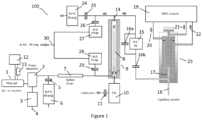
- FIG. 1 illustrates a hydrogen generator system 100 in accordance with the present teachings comprising a polymer electrolyte membrane (PEM) cell which may have an active hydrogen production surface area of the cell membrane of 5 square centimeters or less. For example, from about 1 square centimeter to about 5 square centimeters, or from about 2 square centimeters to about 3 square centimeters.
- the membrane of PEM cell 1 comprises a sulfonated fluoropolymer such as Nafion 115.
- the membrane is in the form of a catalyst coated membrane (CCM) which may have a coating of iridium ruthenium oxide applied to an anode side of the membrane while platinum black may be applied to a cathode side of the membrane.
- CCM catalyst coated membrane
- the membrane of PEM cell 1 should not be confused with the tubular Nafion membrane of Nafion drier 7 or the palladium-silver membrane of palladium purifier 9 described later.
- a secondary limitation may be applied to PEM cell 1 by limiting the hydrogen generation current to 14 amperes or less, such as from about 3 amperes to about 14 amperes, or from about 5 amperes to about 10 amperes applied to a single cell.
- fore-pressure regulated systems measure a pressure decrease in a system and open a valve upstream of the system in order to restore the target pressure.
- An example of this is a common pressure regulator used on a high pressure gas cylinder.
- a backpressure regulated system typically has a constant rate of gas introduction and responds to a pressure increase in the system by opening a pressure relief valve downstream of the system in order to restore the target pressure.
- Demand-based hydrogen generators deliver a variable amount of hydrogen based on demand. If demand increases, the current density of the hydrogen PEM cell or electrolyzer automatically increases to offset the increase in demand. Unfortunately, there is no way for the generator to determine if the increase in demand is related to an operational state of the chromatograph (such as the opening of a split valve) or if the demand increase is related to a leak in the system. This characteristic of demand regulation results in the generator blindly increasing hydrogen production and can translate into sizable leaks going un-noticed and un-checked for long periods of time increasing risk. In a low-flow backpressure regulated system, any leaks in the system do not change flow rate are more likely to be detected due to inadequate instrument performance. Low flow backpressure regulation also allows for steady-state operation of the hydrogen production and purification processes which may translate into lower component stress and prolonged lifetime.
- a constant current power supply (not shown) delivers approximately 1 ampere of current for each 7 sccm of desired flow for a single cell PEM arrangement.
- phase separator 2 may be of conventional design and may comprise a pressure vessel, a float and magnetic or optical switch.
- the float When water enters phase separator 2, the float may perturb or break a light beam between a light emitting diode and phototransistor. This information can trigger a current pulse to a solenoid valve in order to discharge the water while retaining the gas phase hydrogen at a pressure above atmospheric pressure.
- the phase separator 2 may alternatively comprise a Hall effect sensor, a magnetic reed switch, a mechanically operated float switch or other means known in the art.
- the float incorporated into phase separator 2 may comprise a low-density water-resistant solid polymer such as polymethylpentene otherwise known as TPX.
- Float switches for liquid level sensing utilizing TPX are described for example in US6557412 using a Hall Effect sensor for liquid level sensing, or as in Japanese patent JP7117411 using and infrared light beam interrupter.
- the phase separator 2 separates gaseous hydrogen from liquid water and can be configured to discharge water through a solenoid valve 3 and discharge port 4.
- the discharged water may return to a water reservoir 12 serving to feed the PEM cell after first passing through a mixed bed ion exchange resin cartridge (not shown) in a closed-loop arrangement as is conventionally employed in order to remove positively charged trace metallic ions formed from corrosion of metallic components as well as nonmetallic anions formed due to ingress of atmospheric carbon dioxide.
- a non-conventionally employed water pump such as a piezoelectric micropump 13 may be used.
- These types of pumps have very limited flow capacity but have higher reliability than brushless water pumps and lower cost than micro gear pumps. They also can be made much smaller.
- An example of this type of pump is model SDMP320 from Takasago Electric Inc. Japan. This pump has a volumetric flow capacity of 20 milliliters per minute and incorporates a single active moving part.
- the active component comprises a piezoelectric bimorph which acts under the influence of a high voltage low current alternating power supply.
- the size of this pump is a mere 5.5mm in thickness with a length and width of 33mm.
- Piezoelectric pumps are not only reliable, cost effective, small, and self-priming, they also draw less power than pumps used in conventional hydrogen generators.
- the low flow features of piezoelectric micropumps as described are impractical for use on conventional hydrogen generators since they do not have adequate flow rates to clear stagnant oxygen from the PEM cell anode. Stagnant oxygen pockets can result in diminished PEM cell capacity as well as shortened PEM cell lifetime.
- the piezoelectric micropump 13 may have a flowrate of 30 milliliters per minute or less.
- a back pressure regulator 6 in conjunction with a flow limiting element 5 such as a capillary restrictor, sintered frit or orifice can be set to deliver a target pressure upstream of flow limiting element 5 of from about 60 psig to about 150 psig, such as about 80 gauge pounds per square inch (psig).
- the target pressure is selected to be lower than the maximum continuous operational pressure of the PEM cell 1 as defined by the manufacturer, but a preferable pressure may be from about 60psig to about 150psig.
- Back pressure regulator 6 may be a fixed (non-adjustable) mechanically operated pressure relief valve, an adjustable mechanical back pressure regulator or a regulator comprising an electrically driven proportional valve in combination with a pressure transducer, microcontroller, and control firmware.
- a moisture removal device such as a sulfonated tetrafluoroethylene based fluoropolymer-copolymer, also known as a Nafion TM drier 7 can be in the hydrogen flow path upstream of a gas purifier 9.
- driers such as Nafion TM may be preferred, other moisture removal devices may be used. These include silica gel driers, molecular sieve driers and the like.
- An advantage in using Nafion TM is that it does not require periodic regeneration or replacement.
- Nafion TM is expensive, the low flow employed in PEM cell 1 allows for using a drier length of less than 15 centimeters in length.
- a small fan may also act to blow ambient air across the drier surface to improve efficiency.
- an externally applied dry purge gas such as zero air, nitrogen or argon may be applied along the length of a coaxial tube surrounding drier 7 (not shown).
- a vacuum source such as the roughing pump of a gas chromatograph mass spectrometer (GCMS) may be applied externally to drier 7.
- GCMS gas chromatograph mass spectrometer
- the purifier 9 preferably comprises a single linear tube of palladium-silver alloy.
- Prior art palladium purification devices employ a multiplicity of palladium alloy tubes, or a single long tube formed in a coiled configuration. Coiled tubes are compact but have the disadvantage of pressure induced deformation.
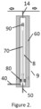
- Palladium purifier 9 may house a palladium alloy membrane 8 comprising an alloy of palladium and silver such as 77% Pd and 23% Ag. This ratio of palladium-to-silver content is preferred and is known to minimize the internal membrane stress when the membrane is exposed to hydrogen when less than about 310 degrees Celsius. Other alloy compositions known in the art may be utilized.
- the palladium alloy membrane 8 may comprise a 2-millimeter outer diameter tube having a wall thickness of 0.06 mm and a length of 60 millimeters. The preferred length of membrane 8 is from about 20mm to about 100mm.
- the preferred diameter of membrane 8 is from about 1mm to about 3mm and the preferred wall thickness of membrane 8 is from about 0.03mm to about 0.1mm.
- the composition of the alloy may be 75% palladium and 25% silver. Preferred ranges of the palladium-silver membrane are from about 15% to about 30% silver.
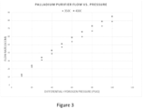
- a tube as described above (2mm outer diameter x 60mm length x 0.06mm wall thickness and composition of 75% Pd and 25% Ag) when heated to 350 degrees Celsius with a pressure drop of 15 psig of pure hydrogen will permeate hydrogen in excess of 10 sccm.
- the pressure-flow characteristics of such a tube is illustrated in Figure 3 .
- Lower amounts of palladium may be utilized than described above but will require higher PEM cell pressure, reduced membrane wall thickness or increased temperature. Operation at lower temperature and pressure facilitates safety, helps to eliminate potential PEM cell water or gas leakage, and results in less component stress which translates into higher reliability.
- the amount of palladium used is a lower amount than conventionally used in hydrogen generators with palladium purifiers because of the low flow demand of back diffusion barrier 17 which requires less than about 10sccm of hydrogen flow.
- the palladium purifier 9 may be heated during operation to a temperature above about 310 degrees Celsius such as 350 degrees Celsius. The preferred range from about 325 degrees Celsius to about 400 degrees Celsius. It is preferable to keep hydrogen from contacting the palladium alloy membrane 8 when the temperature of palladium purifier 9 is below about 310 degrees Celsius. This prevents undue stress fatigue of the membrane 8 which can occur due to temperature induced phase transitions within the alloy structure.
- Membrane terminal end structures 80 and 90 can comprise maraging steel, an alloy of steel or a stainless steel. Membrane terminal end structures 80 and 90 are further silver soldered, vacuum oven brazed, laser welded or otherwise secured in order to confine the impure hydrogen to one side of palladium alloy membrane 8.
- conduit 70 may comprise a short segment of hypodermic needle stock.
- the conduit 70 may be silver soldered, laser welded, vacuum oven brazed or otherwise secured to a larger diameter exit conduit 50.
- the uppermost end of conduit 70 in the illustration is open ended.
- an excess of hydrogen gas produced by PEM cell 1 will enter the palladium purifier 9.
- This excess hydrogen will clear accumulated contamination from palladium alloy membrane 8 by forcing it through pressure regulator 10 which is in series combination with flow restrictor 11.
- the setpoint pressure of the pressure regulator 10 as well as the degree of restriction of restrictor 11 are chosen such that a relatively constant flow is established through the regulator 10 irrespective of the input pressure.
- the flow through regulator 10 may be less than about 10 sccm, such as 5 sccm.
- the pressure regulator 10 may be adjusted such that the back pressure regulator 6 just begins to open.
- Ultra-high purity hydrogen gas exiting conduit 14 establishes a maximum pressure based on back pressure regulator 24.
- the hydrogen pressure upstream of regulator 24 is from about 50 psig to about 70 psig. This will allow sufficient flow of hydrogen to back diffusion barrier 17 when flow restrictor 16b is sized to allow a flow of from about 4sccm to about 10sccm of hydrogen.
- a series flow restrictor 25 may be used to stabilize oscillations in back pressure regulator 24 as well as limit volumetric flow rate. The setpoints of back pressure regulators 6 and 24 largely determine the pressure differential across palladium alloy membrane 8.
- Back pressure regulator 24 is preferably set such that it delivers a small non-zero flow of exit gas such as 0.5 sccm when the GC is in a non-injection state of operation.
- the nonzero flow allows three advantages. First, the non-zero flow allows for outgassed surface impurities of back pressure regulator 24 as well as restrictors 25 and 26 from diffusing into the gas stream feeding normally closed (N.C.) valve 15. (Normally closed and normally open (N.O.) are terms describing the un-powered state of the valve in question rather than the operational state of the valve.) Second, the low non-zero flow of back pressure regulator 24 ensures that high purity hydrogen gas is not wasted to the atmosphere.
- back pressure regulator 24 ensures that when valve 15 is closed, the subsequent pressure rise will result in an immediate flow response in back pressure regulator 24 thereby minimizing the change in differential pressure across palladium alloy membrane 8, since the output pressure will remain relatively unchanged.
- high purity hydrogen is wasted out of the exit of back pressure regulator 24 during injection, the injection interval is typically less than one minute in duration and the wasted flow is less than 10 sccm.
- Back diffusion barrier 17 of a carrier gas-decoupled injection port 23 receives hydrogen gas from valve 15 as well as a non-hydrogen pressurization gas 20 from a digital pressure and flow controller (DPFC) module 19 sometimes referred to as electronic pressure control (EPC).
- DPFC digital pressure and flow controller
- the DPFC module 19 utilizes conventional DPFC hardware but differs operationally in two respects.
- the hardware receives a gas type differing from hydrogen to be used for septum purge flow 21 and split vent flow 22.
- the algorithm used to control the column head pressure is based on the viscosity of hydrogen, while the algorithm used to control split and purge flows are based on the viscosity of the pressurization gas.
- Valve 15 of gas-decoupled injection port 23 has two states of operation. In the energized state, the valve is open and delivers a low flow of hydrogen determined by restrictor 16b to back diffusion barrier 17 such as a flow of from about 4 to about 10 sccm. The flow of hydrogen in the back diffusion barrier 17 occludes the non-hydrogen pressurization gas 20 from entering the GC column 18. In a second state, the valve 15 is de-energized and closed. In the closed state, a small residual hydrogen purge of a few tenths sccm passes through parallel restrictor 16a in order to eliminate solvent back diffusion during injection.
- the pressurization gas preferably comprises argon or nitrogen.
- valve 15 and restrictors 16a and 16b are not strictly necessary for a gas-decoupled injection port to operate. Rather than using a valve to stop or otherwise reduce the flow of hydrogen into back diffusion barrier 17, the DPFC module 19 can instead apply a pressure surge during the injection phase in order to transfer analytes to the column 18.
- a pair of electrically actuated solenoid valves 27 and 28 can receive a non-hydrogen inert purge gas such as argon or nitrogen from a gas entry point 30.
- the pressure of the non-hydrogen purge gas may be higher or lower than the setpoint pressure of back pressure regulators 6 and 24. Setting the pressure higher than the setpoints of back pressure regulators 6 and 24 will allow faster purging of hydrogen when the system is placed in a standby (non-hydrogen producing) condition, or during a power failure such that hydrogen can be rapidly vented through the normally open valves 27 and 28.
- the flow rate of purge gas entering entry point 30 can be governed by flow restrictors 26 and 29.
- Restrictor 29 may be chosen to offer more restriction than restrictor 26 such that the pressure on the input side of palladium alloy membrane 8 will remain higher than the pressure on the output side.
- a pneumatic check valve (not illustrated) can be placed across the input and output of palladium alloy membrane 8 in order to ensure the output pressure will remain in safe limits.
- Tubular metallic alloy membranes with thin wall structures are able to handle higher internal pressures than external pressures due to the tensile strength of the metallic alloy.
- Normally open valves 27 and 28 can remain open during a heat up phase of palladium purifier 9, and close when the purifier rises above a target temperature such as above 340 degrees Celsius.
- valves 27 and 28 can occur in concert with the delivery of power to the PEM cell 1.
- the opening of valves 27 and 28 can occur during a shutdown sequence of the hydrogen generator, during a low power standby condition or during a power failure.
- the opening and closing of valves 27 and 28 may be governed by a timer or in response to an instruction executed by a microprocessor monitoring pressure and/or temperature conditions of PEM cell 1.
- PEM cell 1 may be configured to produce more hydrogen that what is required for operation of the carrier gas decoupled inlet 23. This excess gas may branch off at a point following Nafion drier 7.
- the branched hydrogen may branch upstream of drier 7 and utilize a separate water removal device.
- the branched hydrogen may serve the needs of a flame ionization detector (FID) for the chromatograph which requires a lower level of hydrogen purity from the perspective of residual water vapor and oxygen as does the carrier gas supply.
- FID flame ionization detector
- a hydrogen system 200 comprises a carrier gas decoupled injection port 23 having a back diffusion barrier 17 which receives a low hydrogen flow such as less than 10 sccm hydrogen which passes through a palladium silver membrane 500.
- the palladium silver membrane (which may have the same features as defined above for the gas (palladium) purifier 9 ) is immersed in an electrolytic solution 300 which may comprise a solution of sodium or potassium hydroxide.
- the electrolytic solution 300 may be a 15% concentration in water held in a housing 400.
- the electrolytic solution 300 may alternatively comprise a dilute acid solution such as 5% sulfuric acid in deionized water.
- the palladium silver membrane 500 serves a dual purpose of also acting as a cathode of an electrolytic cell.
- the housing 400 may act as an anode and may comprise a caustic or acid resistant alloy such as Monel or a pure metal such as nickel. Alternatively, the housing 400 may comprise a chemically resistant polymer such as Teflon along with a separate anode.
- the separate anode may comprise platinum or a platinum plated material such as platinum plated titanium. Other electrode compositions may be used.
- EM F electromotive force
- a heating element 700 may surround or be in thermal contact with housing 400 in order to maintain a setpoint temperature from about 60 degree to about 100 degree Celsius, such as 80 degrees Celsius. This elevated temperature will increase the transport efficiency of hydrogen across membrane 500.
- a variable current power supply (not shown) can be controlled by a microcontroller (also not shown) receiving a signal from a pressure sensor 600 in order to supply the necessary current in closed-loop manner to achieve a target pressure on the input of valve 15.
- Valve 15 and other elements of carrier gas decoupled injection port 23 act in similar manner as described in Figure 1 .
- Potential advantages of the embodiment of Figure 4 include reduced size compared with Figure 1 .
- the hydrogen system 200 of Figure 4 does not require a phase separator, gas dryer, mixed bed ion exchange resin, water circulation pump, back pressure regulators or purge valves.
- Membrane 500 may have a surface area no greater than 10 square centimeters, such as no greater than 5 square centimeters.
- the membrane 500 may be from about 1 square centimeter to about 10 square centimeters, such as from about 2 square centimeters to about 8 square centimeters or about 5 square centimeters.
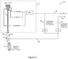
- FIG. 5 illustrates how the carrier gas-decoupled injection port defined herein may be used in a gas chromatograph system 50.
- hydrogen is delivered into tubing 88 that incorporates a fixed gas-flow restrictor 92 .
- a valve 90 allows blockage of hydrogen transport through restrictor 92 .
- an inert gas such as helium, nitrogen or argon, is delivered into a separate tubing 86 from which it serves to pressurize the EPC unit.
- the inert gas can also serve as a residual gas purge by diverting a portion of the inert gas flow through restrictor 94 (which can be enabled by opening of valve 98 ). It is preferred to use an inert gas as the residual purge since even low flows of hydrogen, e.g.
- sccm ⁇ 0.1 standard cubic centimetres per minute
- the purpose of the small residual purge is to prevent back diffusion of solvents and sample into the hydrogen deliver line during sample transfer, and to prevent peak tailing caused by void volume effects.
- hydrogen can be delivered at an upper flow of approximately 5 sccm when valve 90 is in the open state, and valve 98 is in the closed state, and a residual purge of approximately 0.1 sccm of inert gas when valve 90 is in the closed state and valve 98 is in the open state.
- the input pressures of inert gas and hydrogen gas as well as the dimensions of restrictors 92 and 98 can be selected in accordance with the Poiseuille equation such that sufficient hydrogen flow (for prevention of back diffusion of inert gas during analysis) and inert residual gas purge (for prevention of peak tailing) are adequate for the inlet pressure in use.
- a computer algorithm or look up table can be used to set these pressures according to the analytical column dimensions, flow rates and temperatures of the GC method in use.
- a capillary analytical column 23 passes through a tee-piece coupling junction 78, and terminates (i.e., at the column inlet end) within a heated back-diffusion prevention tube 76 whose inner diameter is slightly greater than the outer diameter of the analytical column.
- the entrance to the column 23 as well as the back diffusion prevention tube 76 and tee piece 78 can be heated within a thermal zone 80 which may be under thermal control that is independent of thermal control of the injection port 72 of injector.
- the tee piece 78, and back diffusion prevention tube 76 can alternatively be integrated into the lower portion of injection port 72 utilizing the temperature control of the injection port 72 itself rather than thermal zone 80. In this latter case, it is preferable that the entrance to the analytical column 23 terminates within one centimetre of the entrance to the back diffusion prevention tube 76, thereby providing minimum pressure drop and compactness.
- either hydrogen or an inert gas passes through the tubing 96 and into the tee piece coupler 78 within which it flows "upward" (more specifically, towards the top of the diagram as shown in FIG. 5 ) into an annular gap within the tube 76 that surrounds an inlet portion of the analytical column 23.
- the hydrogen delivered to the tee piece 78 is provided at a flow rate that is somewhat higher than the column flow. For example, 5 mL/min of hydrogen can be delivered for column flows of 1 mL/min. The excess hydrogen will simply be diverted "upwards" (more specifically, towards the top of the diagram as shown in FIG. 5 ) where it contributes to the bulk purge gas used for septum purge and split flow control.
- embodiments of the described invention provide a solution for hydrogen use in chromatographs that offer reduced chemical reactions, increased safety and reduced maintenance.
Landscapes
- Chemical & Material Sciences (AREA)
- Chemical Kinetics & Catalysis (AREA)
- Engineering & Computer Science (AREA)
- Organic Chemistry (AREA)
- Electrochemistry (AREA)
- Metallurgy (AREA)
- Materials Engineering (AREA)
- Analytical Chemistry (AREA)
- General Chemical & Material Sciences (AREA)
- Oil, Petroleum & Natural Gas (AREA)
- Life Sciences & Earth Sciences (AREA)
- Inorganic Chemistry (AREA)
- General Health & Medical Sciences (AREA)
- Health & Medical Sciences (AREA)
- Pathology (AREA)
- Biochemistry (AREA)
- Physics & Mathematics (AREA)
- Immunology (AREA)
- General Physics & Mathematics (AREA)
- Sustainable Development (AREA)
- Combustion & Propulsion (AREA)
- Water Supply & Treatment (AREA)
- Environmental & Geological Engineering (AREA)
- Hydrology & Water Resources (AREA)
- Separation Using Semi-Permeable Membranes (AREA)
- Hydrogen, Water And Hydrids (AREA)
- Electrolytic Production Of Non-Metals, Compounds, Apparatuses Therefor (AREA)
Applications Claiming Priority (1)
| Application Number | Priority Date | Filing Date | Title |
|---|---|---|---|
| US202263387953P | 2022-12-18 | 2022-12-18 |
Publications (2)
| Publication Number | Publication Date |
|---|---|
| EP4424878A2 true EP4424878A2 (de) | 2024-09-04 |
| EP4424878A3 EP4424878A3 (de) | 2025-03-05 |
Family
ID=89223545
Family Applications (1)
| Application Number | Title | Priority Date | Filing Date |
|---|---|---|---|
| EP23217254.4A Pending EP4424878A3 (de) | 2022-12-18 | 2023-12-15 | Wasserstoffgenerator für gaschromatographieanwendungen |
Country Status (3)
| Country | Link |
|---|---|
| US (1) | US20240200216A1 (de) |
| EP (1) | EP4424878A3 (de) |
| CN (1) | CN118207560A (de) |
Families Citing this family (1)
| Publication number | Priority date | Publication date | Assignee | Title |
|---|---|---|---|---|
| EP4715380A1 (de) * | 2024-09-23 | 2026-03-25 | Advanced Monitoring Solutions AS | System zur wasserstoffdetektion bei geringen volumenmischverhältnissen |
Citations (5)
| Publication number | Priority date | Publication date | Assignee | Title |
|---|---|---|---|---|
| US6557412B1 (en) | 2000-10-23 | 2003-05-06 | William J. Barbier | Non-fouling liquid level control |
| US8371152B2 (en) | 2010-10-27 | 2013-02-12 | Thermo Finnigan Llc | Helium conservation device for a gas chromatograph |
| US9632064B2 (en) | 2014-05-13 | 2017-04-25 | Thermo Finnigan Llc | Gas chromatograph system employing hydrogen carrier gas |
| US11255828B2 (en) | 2020-04-02 | 2022-02-22 | Thermo Finnigan Llc | Carrier gas reduction for gas chromatography |
| JP7117411B2 (ja) | 2016-08-19 | 2022-08-12 | 積水化学工業株式会社 | 粘着テープ |
Family Cites Families (2)
| Publication number | Priority date | Publication date | Assignee | Title |
|---|---|---|---|---|
| US20110233069A1 (en) * | 2010-03-24 | 2011-09-29 | Rasirc | Method and system for electrochemical hydrogen generation |
| CN204849043U (zh) * | 2014-12-04 | 2015-12-09 | 南京工业大学 | 一种超高纯氢气发生器 |
-
2023
- 2023-11-10 US US18/506,432 patent/US20240200216A1/en active Pending
- 2023-12-15 EP EP23217254.4A patent/EP4424878A3/de active Pending
- 2023-12-18 CN CN202311740819.7A patent/CN118207560A/zh active Pending
Patent Citations (5)
| Publication number | Priority date | Publication date | Assignee | Title |
|---|---|---|---|---|
| US6557412B1 (en) | 2000-10-23 | 2003-05-06 | William J. Barbier | Non-fouling liquid level control |
| US8371152B2 (en) | 2010-10-27 | 2013-02-12 | Thermo Finnigan Llc | Helium conservation device for a gas chromatograph |
| US9632064B2 (en) | 2014-05-13 | 2017-04-25 | Thermo Finnigan Llc | Gas chromatograph system employing hydrogen carrier gas |
| JP7117411B2 (ja) | 2016-08-19 | 2022-08-12 | 積水化学工業株式会社 | 粘着テープ |
| US11255828B2 (en) | 2020-04-02 | 2022-02-22 | Thermo Finnigan Llc | Carrier gas reduction for gas chromatography |
Non-Patent Citations (2)
| Title |
|---|
| A.S. DARLING: "Thermal and Electrolytic Palladium Alloy Diffusion Cells", PLATINUM METALS REV., vol. 7, 1963, pages 126 |
| J.K. JACOBSEN: "Ultrapure Hydrogen Generator for Gas Chromatography", ANAL. CHEM., vol. 37, no. 2, 1 February 1965 (1965-02-01), pages 319 - 320 |
Also Published As
| Publication number | Publication date |
|---|---|
| CN118207560A (zh) | 2024-06-18 |
| US20240200216A1 (en) | 2024-06-20 |
| EP4424878A3 (de) | 2025-03-05 |
Similar Documents
| Publication | Publication Date | Title |
|---|---|---|
| JP6523273B2 (ja) | 水素システム及び動作の方法 | |
| CN104620103B (zh) | 多组分洗脱液产生系统和方法 | |
| EP4424878A2 (de) | Wasserstoffgenerator für gaschromatographieanwendungen | |
| JP2019526446A (ja) | 水素同位体を濃縮する為の装置及び方法 | |
| CA2453523C (en) | Thin-channel electrospray emitter | |
| JP4627037B2 (ja) | 接触燃焼式ガスセンサ | |
| EP4339330A2 (de) | Elektrolysevorrichtung und verfahren zur steuerung der elektrolysevorrichtung | |
| GB2582049A (en) | Method for operating an electrolysis system and electrolysis system | |
| EP3776628B1 (de) | Imr-ms-vorrichtung | |
| JP6080223B2 (ja) | 空気呼吸式燃料電池、電池スタックおよび電池スタックのバッテリーとしての利用 | |
| US20250102479A1 (en) | Method of utilizing deuterium gas for chromatography applications, deuterium gas generator and devices for conservation thereof | |
| US8323850B2 (en) | Direct methanol fuel cell liquid fuel with water and methanol having specific electrical resistance and direct methanol fuel cell cartridge | |
| EP4206670B1 (de) | Neuartige konfiguration für ultrahochdruck-eluentgeneratoren | |
| JP2003510787A (ja) | 燃料電池の電解質中のアルコール濃度の測定方法と装置 | |
| JP2007035489A (ja) | 燃料電池システム及び燃料電池システムの制御方法 | |
| CN101377477A (zh) | 离子色谱淋洗液自动发生装置 | |
| CN116323500B (zh) | 电解池及臭氧水散布装置 | |
| CN113646629B (zh) | 离子色谱仪 | |
| CN115558949A (zh) | 分离供电式氢气富集提纯加压电化学氢泵系统 | |
| RU2229325C1 (ru) | Электродиализный генератор элюента для ионной хроматографии | |
| JP2026073734A (ja) | 水素供給システムおよび参照電極システム | |
| CN120629308A (zh) | 电极过电位测试系统及测试方法 | |
| JPWO2020054334A1 (ja) | 水素生成システム及び水素生成システムの運転方法 | |
| JP2016162644A (ja) | 燃料電池システム | |
| JP2001330585A (ja) | 一酸化炭素センサ |
Legal Events
| Date | Code | Title | Description |
|---|---|---|---|
| PUAI | Public reference made under article 153(3) epc to a published international application that has entered the european phase |
Free format text: ORIGINAL CODE: 0009012 |
|
| STAA | Information on the status of an ep patent application or granted ep patent |
Free format text: STATUS: THE APPLICATION HAS BEEN PUBLISHED |
|
| AK | Designated contracting states |
Kind code of ref document: A2 Designated state(s): AL AT BE BG CH CY CZ DE DK EE ES FI FR GB GR HR HU IE IS IT LI LT LU LV MC ME MK MT NL NO PL PT RO RS SE SI SK SM TR |
|
| PUAL | Search report despatched |
Free format text: ORIGINAL CODE: 0009013 |
|
| AK | Designated contracting states |
Kind code of ref document: A3 Designated state(s): AL AT BE BG CH CY CZ DE DK EE ES FI FR GB GR HR HU IE IS IT LI LT LU LV MC ME MK MT NL NO PL PT RO RS SE SI SK SM TR |
|
| RIC1 | Information provided on ipc code assigned before grant |
Ipc: G01N 30/02 20060101ALI20250130BHEP Ipc: B01D 53/26 20060101ALI20250130BHEP Ipc: B01D 53/22 20060101ALI20250130BHEP Ipc: B01D 53/02 20060101ALI20250130BHEP Ipc: B01D 63/06 20060101ALI20250130BHEP Ipc: G01N 30/28 20060101ALI20250130BHEP Ipc: C25B 15/08 20060101ALI20250130BHEP Ipc: C25B 1/04 20210101ALI20250130BHEP Ipc: C25B 11/093 20210101ALI20250130BHEP Ipc: C25B 9/23 20210101AFI20250130BHEP |
|
| STAA | Information on the status of an ep patent application or granted ep patent |
Free format text: STATUS: REQUEST FOR EXAMINATION WAS MADE |
|
| 17P | Request for examination filed |
Effective date: 20250729 |