EP4424459A1 - Vorrichtung und verfahren zum applizieren eines umlaufenden dichtungsprofils auf einem karosseriebauteil - Google Patents
Vorrichtung und verfahren zum applizieren eines umlaufenden dichtungsprofils auf einem karosseriebauteil Download PDFInfo
- Publication number
- EP4424459A1 EP4424459A1 EP24156056.4A EP24156056A EP4424459A1 EP 4424459 A1 EP4424459 A1 EP 4424459A1 EP 24156056 A EP24156056 A EP 24156056A EP 4424459 A1 EP4424459 A1 EP 4424459A1
- Authority
- EP
- European Patent Office
- Prior art keywords
- sealing profile
- guide element
- pressing unit
- body component
- free end
- Prior art date
- Legal status (The legal status is an assumption and is not a legal conclusion. Google has not performed a legal analysis and makes no representation as to the accuracy of the status listed.)
- Pending
Links
Images



Classifications
-
- B—PERFORMING OPERATIONS; TRANSPORTING
- B23—MACHINE TOOLS; METAL-WORKING NOT OTHERWISE PROVIDED FOR
- B23P—METAL-WORKING NOT OTHERWISE PROVIDED FOR; COMBINED OPERATIONS; UNIVERSAL MACHINE TOOLS
- B23P19/00—Machines for simply fitting together or separating metal parts or objects, or metal and non-metal parts, whether or not involving some deformation; Tools or devices therefor so far as not provided for in other classes
- B23P19/04—Machines for simply fitting together or separating metal parts or objects, or metal and non-metal parts, whether or not involving some deformation; Tools or devices therefor so far as not provided for in other classes for assembling or disassembling parts
- B23P19/047—Machines for simply fitting together or separating metal parts or objects, or metal and non-metal parts, whether or not involving some deformation; Tools or devices therefor so far as not provided for in other classes for assembling or disassembling parts for flexible profiles, e.g. sealing or decorating strips in grooves or on other profiles by devices moving along the flexible profile
-
- B—PERFORMING OPERATIONS; TRANSPORTING
- B29—WORKING OF PLASTICS; WORKING OF SUBSTANCES IN A PLASTIC STATE IN GENERAL
- B29C—SHAPING OR JOINING OF PLASTICS; SHAPING OF MATERIAL IN A PLASTIC STATE, NOT OTHERWISE PROVIDED FOR; AFTER-TREATMENT OF THE SHAPED PRODUCTS, e.g. REPAIRING
- B29C65/00—Joining or sealing of preformed parts, e.g. welding of plastics materials; Apparatus therefor
- B29C65/56—Joining or sealing of preformed parts, e.g. welding of plastics materials; Apparatus therefor using mechanical means or mechanical connections, e.g. form-fits
- B29C65/64—Joining a non-plastics element to a plastics element, e.g. by force
-
- B—PERFORMING OPERATIONS; TRANSPORTING
- B25—HAND TOOLS; PORTABLE POWER-DRIVEN TOOLS; MANIPULATORS
- B25B—TOOLS OR BENCH DEVICES NOT OTHERWISE PROVIDED FOR, FOR FASTENING, CONNECTING, DISENGAGING, OR HOLDING
- B25B27/00—Hand tools, specially adapted for fitting together or separating parts or objects whether or not involving some deformation, not otherwise provided for
- B25B27/0092—Tools moving along strips, e.g. decorating or sealing strips, to insert them in, or remove them from, grooves or profiles
-
- B—PERFORMING OPERATIONS; TRANSPORTING
- B29—WORKING OF PLASTICS; WORKING OF SUBSTANCES IN A PLASTIC STATE IN GENERAL
- B29C—SHAPING OR JOINING OF PLASTICS; SHAPING OF MATERIAL IN A PLASTIC STATE, NOT OTHERWISE PROVIDED FOR; AFTER-TREATMENT OF THE SHAPED PRODUCTS, e.g. REPAIRING
- B29C65/00—Joining or sealing of preformed parts, e.g. welding of plastics materials; Apparatus therefor
- B29C65/78—Means for handling the parts to be joined, e.g. for making containers or hollow articles, e.g. means for handling sheets, plates, web-like materials, tubular articles, hollow articles or elements to be joined therewith; Means for discharging the joined articles from the joining apparatus
- B29C65/7802—Positioning the parts to be joined, e.g. aligning, indexing or centring
-
- B—PERFORMING OPERATIONS; TRANSPORTING
- B29—WORKING OF PLASTICS; WORKING OF SUBSTANCES IN A PLASTIC STATE IN GENERAL
- B29C—SHAPING OR JOINING OF PLASTICS; SHAPING OF MATERIAL IN A PLASTIC STATE, NOT OTHERWISE PROVIDED FOR; AFTER-TREATMENT OF THE SHAPED PRODUCTS, e.g. REPAIRING
- B29C66/00—General aspects of processes or apparatus for joining preformed parts
- B29C66/70—General aspects of processes or apparatus for joining preformed parts characterised by the composition, physical properties or the structure of the material of the parts to be joined; Joining with non-plastics material
- B29C66/74—Joining plastics material to non-plastics material
- B29C66/742—Joining plastics material to non-plastics material to metals or their alloys
Definitions
- the invention relates to an application device for applying a circumferential sealing profile to a body component, comprising an application head, wherein the application head comprises a pressing unit and a feed unit, wherein the feed unit is designed to feed a sealing profile to be applied to the pressing unit via a sealing profile inlet of the pressing unit, and wherein the pressing unit is designed to apply a fed sealing profile to the body component via a sealing profile outlet of the pressing unit. Furthermore, the invention relates to a method for applying a circumferential sealing profile to a body component, wherein the sealing profile to be applied is fed to a pressing unit, the pressing unit is moved relative to the body component, and the sealing profile is applied to the body component by means of the pressing unit.
- An application device for applying a sealing profile to a body component used to close a body opening with a rolling head for applying the sealing profile is known, for example, from EN 10 2017 221 018 B3 known. From the DE 101 38 781 A1
- Another application device for applying a sealing profile using a robot is known, with which a sealing profile is successively pressed onto a surface of a vehicle door following a predetermined assembly line using pressure rollers and thus applied.
- an application device is described in the EN 10 2011 050 750 A1 an application device is described. With regard to the application device, it is shown that the sealing profile is guided up to the sealing profile inlet.
- the guide part also called the mouthpiece, which guides the sealing profile on the pressure roller and holds it in position holds, cannot be arranged directly near the application point for reasons of space, but has a certain distance from the application point, at the end of the application process the last sealing profile piece runs out of this guide part as the free end of the sealing profile.
- the pressure roller rolls over it, it can therefore happen that the sealing profile end is not glued in a sufficiently positioned position and for this reason there can be misalignments in the sealing joint area from the beginning of the sealing profile to the end of the sealing profile.
- the proposed solution provides an application device for applying a circumferential sealing profile to a body component, in particular a vehicle body or a part of the vehicle body, in particular a vehicle door.
- the application device comprises an application head, wherein the application head has a pressing unit, in particular a pressing roller, and a feed unit.
- the feed unit is designed to feed a sealing profile to be applied to the pressing unit via a sealing profile inlet of the pressing unit.
- the pressing unit is designed to apply a fed sealing profile to the body component via a sealing profile outlet of the pressing unit.
- the application head further comprises a guide element, wherein the guide element is designed in a working position to guide a free end of a sealing profile to be applied that has left the sealing profile inlet of the pressing unit.
- the guide element takes over the guidance of a sealing profile, especially when guidance cannot be provided, or at least no longer fully provided, by the pressing unit or by a mouthpiece associated with the pressing unit.
- the sealing profile inlet extends in particular to the pressing unit, in particular to the pressure roller.
- the application device can comprise at least one further guide element, which guides the sealing profile in particular to the sealing profile inlet.
- at least one first guide element of the application device then advantageously guides the sealing profile to the sealing profile inlet, for example as in Fig.1 the EN 10 2011 050 750 A1 shown.
- At least one second guide element of the application device guides a free end of the sealing profile when the free end has left the sealing profile inlet of the pressing unit and the at least one second guide element is in the working position.
- the mouthpiece is in particular a first guide element.
- guide element means the “at least one second guide element", i.e. the guide element which is designed in a working position to guide a free end of a sealing profile to be applied which has left the sealing profile inlet of the pressing unit.
- the guide element according to the invention advantageously provides additional guidance so that a free end of a sealing profile, in particular a sealing profile end piece, is also guided until it is applied to the body component.
- the free end is thus advantageously guided by the guide element even when it is applied to the body component.
- the guide element advantageously also counteracts any possible tendency of the free end of the sealing profile to adopt a different orientation than that intended for application due to the shape memory of the sealing profile. This is because the guide element advantageously holds the free sealing profile on the line intended for the application of the sealing profile. Thanks to the guide element, a free end of a sealing profile can therefore be positioned with high precision.
- the application head of the application device is an application head for applying a sealing profile in a roof opening of a vehicle body, in particular a roof opening for a sliding or panoramic roof.
- the guide element is designed such that a free end of a sealing profile is guided by the guide element at least from one side, with the guide element advantageously supporting the free end from at least one side.
- a guide element is also provided in particular in which a free end of a sealing profile is guided by the guide element on both long sides of the sealing profile, with the guide element in this case preferably being designed in several pieces.
- the guide element also advantageously has an inlet slope via which the free end of the sealing profile can easily reach the guide area of the guide element.
- the guide area of the guide element is in particular the area of the guide element in which the free end of a sealing profile is guided for correct alignment of the free end for subsequent application.
- the guide area of the guide element is therefore formed in particular by a section of the guide element facing a body component to which a sealing profile is to be applied.
- a further advantageous embodiment provides that the guide element is arranged in the working position in front of the sealing profile outlet in relation to a direction in which a sealing profile is applied to a body component.
- this allows a free end of a sealing profile, in particular a free end of a sealing profile that has already left the sealing profile inlet of the pressing unit and has moved from the guide area of the pressing unit to the body component in particular due to elastic restoring forces of the sealing profile, to be guided through the guide element and suitably positioned so that this free end can then be applied by the pressing unit along the intended line.
- This embodiment is particularly advantageous if the pressing unit is designed as a pressing roller.
- the guide element is also advantageously arranged in the working position in such a way that a free end of a sealing profile to be applied is at least partially supported by the guide element before reaching the sealing profile outlet, in particular supported against gravity.
- the guide element advantageously prevents the free end from leaving the intended application line due to gravity. This design thus advantageously contributes further to a high level of impact accuracy.
- the guide element has a support surface for supporting the free end. If the guide element also has an inlet slope, the The inlet slope as a surface advantageously merges into the support surface in the direction of the component to which the sealing profile is applied.
- the guide element is arranged on the application head in the working position in such a way that a guide region of the guide element extends parallel to a body component surface to which a sealing profile is applied.
- this embodiment provides that the guide region of the guide element extends parallel to a provided application line on a body component surface.
- the guide region is in particular the region of the guide element that takes over the guidance of a free end of a sealing profile to be applied for correct alignment of the free end for the subsequent application.
- at least part of the support surface can be encompassed by the guide region, wherein the support surface is advantageously aligned orthogonally to the surface of the body component to which the sealing profile is to be applied.
- the guide element in the working position is further advantageously arranged on the application head in such a way that the guide region of the guide element is aligned in a flush line with a guide of the pressing unit, and in this respect advantageously forms an extension of the guide through the pressing unit.
- a further advantageous embodiment of the application device provides that the application head has a mouthpiece associated with the sealing profile inlet of the pressing unit, wherein the mouthpiece is designed to guide the sealing profile fed to the pressing unit.
- the mouthpiece is a first guide element encompassed by the at least one first guide element.
- the distance between the guide element in the working position and the sealing profile outlet preferably corresponds at most to the distance between the mouthpiece and the sealing profile outlet.
- the distance between the guide element in the working position and the sealing profile outlet is less than or equal to 30 mm.
- the distance between the guide element in the working position and the sealing profile outlet should therefore advantageously not be greater than 30 mm.
- the distance is between 10 mm and 30 mm. This distance also advantageously ensures that a free end of a sealing profile to be applied, which loses guidance when it leaves the sealing profile inlet, can be guided almost seamlessly by the guide element. In this respect, maintaining this distance also helps to enable application with high precision along a specified application line for an entire remaining end piece of a sealing profile to be applied.
- the guide element is adjustable between the working position and a rest position. In the rest position, it is advantageously not possible to guide a sealing profile to be applied.
- the guide element is designed to be pivotable, wherein the guide element is adjustable by pivoting between the working position and the rest position.
- the application device advantageously comprises at least one sensor unit assigned to the guide element, which is designed to determine whether the guide element is in the rest position or in the working position.
- the guide element is also advantageously adjustable between the working position and the rest position by means of an actuator unit of the application device.
- the application device is advantageously set up in such a way that the guide element is only moved from the rest position to the working position when the free end of a sealing profile to be applied leaves the sealing profile inlet or shortly before the free end of a sealing profile to be applied leaves the sealing profile inlet, in particular when the free end of a sealing profile to be applied fed to the pressing unit reaches the sealing profile inlet.
- the application device is further set up in such a way that when an application process of a circumferential sealing profile on a body component is completed, the guide element is moved back from the working position to the rest position.
- the guide element is provided to remain in the working position until a free end of a starting piece of a sealing profile to be applied is The pressure unit is applied to a body component and only then is the guide element moved from the working position back to the rest position.
- the adjustability of the guide element from a working position to a rest position has the advantage that during application beyond the free ends, whereby sufficient guidance is realized by the pressing unit, the guide element can be in the rest position and thus advantageously no undesirable contact can occur between the guide element and the body component.
- the application head has a mouthpiece associated with the sealing profile inlet of the pressing unit, wherein the mouthpiece is designed to guide the sealing profile fed to the pressing unit, wherein the application device is designed to adjust the guide element from the rest position to the working position when a free end of a sealing profile to be applied has reached a predetermined position in relation to the mouthpiece.
- a design variant of the application device in which the application device is set up for applying a sunroof seal in a body opening, provides, however, that the guide element is fixed to the application head and the guide element is thus advantageously always in the working position.
- moving the guide element into a rest position is advantageously unnecessary because a collision is ruled out due to the application around the body opening.
- it can be advantageous for the guide element to remain in the working position because a sealing profile section that has just been applied can also be supported by the guide element and the result of the application process can thus be further improved.
- the method for applying a circumferential sealing profile to a body component, in particular for applying a circumferential sunroof sealing profile in a body opening which is further proposed to solve the problem mentioned at the outset, provides that the sealing profile to be applied is fed to a pressing unit, in particular a pressing roller, the pressing unit is moved relative to the body component, the sealing profile is applied to the body component by means of the pressing unit, and a free End of the sealing profile is guided by a guide element before being applied to the body component, in particular immediately before being applied to the body component, and advantageously also during application to the body component.
- the proposed method thus advantageously guides the free ends of a sealing profile that is being applied, in particular guides a starting piece of a sealing profile to be applied and guides an end piece of a sealing profile to be applied.
- This guidance advantageously ensures that no offset, or at least only an extremely small offset, which is in particular less than 0.5 mm, is formed between the start of the sealing profile and the sealing profile. This advantageously means that joints are not visually noticeable.
- the method is particularly advantageous when applying sunroof sealing profiles because these have the property of returning to their original shape without guidance, even more so than, for example, body door sealing profiles.
- the guide with the guide element is provided in particular in addition to a possible guide that begins before the sealing profile inlet and is particularly intended to correctly feed the sealing profile to the pressing unit.
- a first guide can be provided up to the sealing profile inlet, and a second guide can be provided downstream of the first guide in the direction of movement of the sealing profile, wherein the second guide guides a free end of the sealing profile, in particular exclusively a free end of the sealing profile, in particular until immediately before the free end is applied to the body component, i.e. in particular until the free end contacts the body component.
- the pressing unit is arranged on an application head, wherein the application head is arranged on a robot arm and is moved along the body component to apply the sealing profile.
- a stationary arrangement of the robot head can also be provided, in which the body component is moved along the application head or the pressing unit to apply the sealing profile.
- the application head is an application head for applying a sealing profile in a roof opening of a vehicle body, in particular a roof opening for a sliding and/or panoramic roof.
- the guide element advantageously guides the free end at least along one long side of the sealing profile.
- the guide element guides the free end on both sides.
- the guide element grips around the free end. This advantageously improves the guidance and thus ultimately the joint quality. improved.
- the guide element also advantageously supports the free end of the sealing profile to be applied, in particular against gravity, whereby the application result is advantageously further improved.
- this support of the sealing profile is also advantageous when applying a sunroof seal in a body opening, because this advantageously prevents the sealing profile that has just been applied from sagging even better.
- An advantageous embodiment of the method provides that the guide element for guiding the free end of the sealing profile is moved from a rest position, in which no guidance can take place, to a working position, in which guidance can take place.
- the guide element is pivoted from the rest position to the working position or from the working position to the rest position as required.
- the position that the guide element has assumed is advantageously monitored, in particular by sensors.
- the guide element remains in the rest position until a free end of a sealing profile that is applied to a body component has reached a predetermined distance in relation to the pressing unit, in particular a predetermined distance in relation to a mouthpiece assigned to the pressing unit. Until then, the sealing profile is guided in particular by the pressing unit itself or by the mouthpiece when it enters the pressing unit.
- the guide element When the predetermined position, which represents the predetermined distance, is reached, the guide element is advantageously moved from the rest position to the working position. If the free end now runs out of a sealing profile inlet of the pressing unit, in particular from the mouthpiece, this free end is advantageously guided by the guide element and held in position in order to be applied to a designated application line on the body component by the pressing unit. Once the sealing profile has been fully applied, the guide element can be returned to the rest position.
- the guide element for guiding and/or positioning a sealing profile start that has not yet reached the sealing profile end initially remains in the working position or is brought back into the working position for this purpose.
- the guide element is brought into the rest position at the latest when the starting piece of the sealing profile has been applied.
- a sealing profile is applied around a body opening, such as in particular when applying a sunroof seal, it can be provided that the guide element remains in the working position the entire time.
- the sealing profile is applied using an application device designed according to the invention.
- the application device has in particular the features described above individually or in a suitable combination.
- FIG.1 an embodiment of an application device 1 designed according to the invention is shown.
- the application device 1 comprises an application head 3, which in the embodiment shown is arranged stationary on a carrier 15.
- the application head 3 is arranged on a robot arm.
- the application head 3 comprises a pressing unit 4 designed as a pressure roller, a feed unit 5, a separating unit (not explicitly shown) and a guide element 8.
- a Fig.1 The endless sealing profile 2 provided on a supply roll (not shown) is thereby, in particular via a likewise Fig.1 buffer unit (not shown), to the application head 3.
- the feed unit 5 is designed to feed the sealing profile 2 to the pressing unit 4 for application to a body component, for which purpose the feed unit 5 comprises, in particular in a known manner, a plurality of rollers via which the sealing profile 2 is guided to the pressing unit 4.
- the pressing unit 4 is designed to apply a supplied sealing profile 2 to a body component.
- the separating unit separates the sealing profile 2 in such a way that the sealing profile 2 has the length required for the circumferential attachment to the body component.
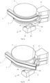
- the guide element 8 arranged on the application head 3 is now designed to guide such a free end 21, 22 of a sealing profile 2 to be applied in order to improve the joint quality of a sealing profile 2 applied all the way around a body component. Details for advantageous embodiments of an application head 3, in particular for advantageous embodiments of a pressing unit 4 designed as a pressure roller and a guide element 8 assigned to the pressing unit 4 are described below with reference to Fig. 2 , on Fig. 3a to Fig. 3c , on Fig. 4a and Fig. 4b as well as on Fig. 5a and Fig. 5b explained in more detail.
- Fig. 2 shows a section of an application head 3 with a pressing unit 4 designed as a pressure roller and a Guide element 8, whereby a sealing profile 2 is applied to a body component by means of the pressing unit 4. Since the body component would cover the application head 3, the body component is in Fig. 2 not shown.
- a sealing profile beginning 21, which is Fig. 2 is only shown as a section, and in reality the beginning of the leftmost part of Fig. 2
- the sealing profile 2 to be applied to the body component should be applied starting at the left end of the section shown and then continuing to the right in the application direction 50.
- the sealing profile 2 to be applied to the body component is Fig. 2 As shown in the illustration, the sealing profile 2 has already been almost completely applied to the body component by means of the pressing unit 4. This leaves only a small piece 40 of the body component surface intended for the application of the sealing profile, on which the sealing profile 2 has not yet been applied.
- the pressing unit 4 is arranged on the application head 3 in such a way that a sealing profile inlet 6 and a sealing profile outlet 7 are formed for the pressing unit 4.
- a Fig.2 A feed unit (not explicitly shown) feeds the sealing profile 2 to be applied to the sealing profile inlet 6 of the pressing unit 4.
- a mouthpiece 11 arranged on the application head 3 and assigned to the sealing profile inlet 6 of the pressing unit 4 guides the sealing profile 2 as a first guide element and threads the sealing profile 2 into the pressing unit 4 so that the sealing profile 2 can always be picked up by the pressing unit 4 for the subsequent application as long as a free end 22 of the sealing profile 2 to be applied has not yet been reached.
- the pressing unit 4 which is designed as a pressure roller, also provides a guide for the sealing profile 2 by means of an upper limit 41 and a lower limit 42. During application, the sealing profile 2 is pressed against the body component by the pressing unit 4 and applied to the body component via the sealing profile outlet 7 of the pressing unit 4.
- a sealing profile end 22 has now left the mouthpiece 11 and thus the sealing profile inlet 6, it can no longer be guided by the mouthpiece 11. Due to the so-called shape memory of the sealing profile 2, the sealing profile end 22 moves towards the body component. The guidance of this free end 22 of the sealing profile is now taken over by the guide element 8 located in the working position 9, which is arranged in the working position 9 in front of the sealing profile outlet 7 on the application head 3 with respect to the direction 50 in which the sealing profile 2 is currently being applied to the body component.
- the guide element 8 is in this respect in particular a second guide element, i.e. a further guide element in addition to the mouthpiece and/or a guide element upstream guide.
- the distance between the guide element 8 in the working position 9 and the sealing profile outlet 7 is approximately 3 cm (cm: centimetres) and is thus advantageously slightly smaller than the distance between the mouthpiece 11 and the sealing profile outlet 7.
- the assumption of the guidance of the free end 22 of the sealing profile 2 by the guide element 8 is described with reference to Fig. 3a to Fig. 3c explained in more detail.
- Fig. 3a represents the time of application as in Fig.2 , i.e. shortly before the end of the application process, at which the sealing profile end 22 has not yet left the mouthpiece 11 and thus the sealing profile inlet 6.
- the sealing profile 2 is thus still guided by the mouthpiece 11.
- the guide element 8 in this embodiment has a first guide area 81, an inlet slope 82 and a support surface 83, the function of which is explained below.
- the guide element 8 in this embodiment has a recess 86, the shape of which is designed to match the shape of the pressing unit 4 designed as a pressure roller, and serves to be able to arrange the guide element 8 close to the pressing unit 4 in a stable design without the guide element 8 restricting the function of the pressing unit 4. It can be provided that the guide element 8 can be pivoted about a rotation axis of the pressing unit 4 between a working position and a rest position.
- Fig. 3b now shows a subsequent time to the representation in Fig. 3a , wherein at this subsequent point in time the free end 22 of the sealing profile 2 has left the mouthpiece 11 and thus the sealing profile inlet 6 and the mouthpiece 11 can therefore no longer guide the free end 22. Since the sealing profile 2 is elastic, the free end 22 of the sealing profile moves towards the body component, wherein the inlet slope 82 of the guide element 8 ensures that the free end 2 reliably reaches the guide area 81 for the free end 22 and does not become jammed with the guide element 8 and get caught on the rear part of the guide element 8.
- the guide area 81 in particular the edge of the guide area facing the body component, extends essentially parallel to the body component surface to which the sealing profile 2 is to be applied, in particular parallel to a provided application line on the body component surface.
- the support surface 85 is essentially orthogonal to that of the body component surface so that a substantially right angle is formed between the body component surface to which the sealing profile 2 is to be applied and the support surface.
- Fig. 3c again shows a later point in time in relation to Fig. 3b .
- the free end 22 of the sealing profile 2 has moved over the run-in slope 82 into the guide area 81, where the free end 22 is supported by the support surface 83 of the guide element 8 before reaching the sealing profile outlet 7. Due to this support and the resulting guidance of the guide element 8, the free end 22 can be applied without offset to the already applied sealing profile start 21, as is particularly the case with the embodiment in Fig. 5a shown.
- Fig. 4a shows an advantageous design variant to the Fig. 3a to Fig. 3c shown embodiment.
- the guide element 8 has an upper guide part 89 in addition to a lower guide part 88, so that the free end 22 of the sealing profile 2 is guided along both long sides by the guide element 8.
- Fig. 4b is a further advantageous design variant to the Fig. 3a to Fig. 3c shown embodiment.
- the guide element 8 is adjustable between one of several possible working positions 9, 9 ⁇ and a rest position 10, in which no guidance of a sealing profile 2 to be applied can take place through the guide element 8.
- the guide element 8 is designed to be pivotable about a rotation axis, as shown by way of example in Fig. 4b Only for guiding a free end 21, 22, the guide element 8 is moved from the rest position 10, which is in Fig. 4b symbolically represented by a dot-dash line, into the respective working position 9, 9 ⁇ .
- the application device is designed to adjust the guide element 8 from the rest position 10 into a first working position 9 when a sealing profile end 22 of a sealing profile 2 to be applied has reached a predetermined position in relation to the mouthpiece 11.
- the guide element 8 then acts as described with reference to Fig. 3a to Fig. 3c
- the guide element 8 is slightly raised, as indicated by the double arrow in Fig. 4b symbolically shown, and thus moved to a second working position 9 ⁇ .
- a second guide area 84 of the guide element 8 with a second inlet slope 85 is then ready to guide a new sealing profile start 21 for a further application process after leaving the mouthpiece 11 and thus after leaving the sealing profile inlet 6 until reaching the sealing profile outlet 7.
- the sealing profile start 21 then meets the second Inlet slope 85 of the guide element 8 and is supported by the second guide area 84.
- the surface of the inlet slope 85 is advantageously specially treated to prevent adhesive from being removed from the sealing profile start or the sealing profile start from sticking.
- a film in particular a thin adhesive film, is applied to the inlet slope 85 so that a sealing profile start 21 can advantageously slide over the inlet slope 85.
- Fig. 5a and Fig. 5b show in a front view two possible designs that differ in the design of the guide element 8.
- a lower guide part 88 is provided, whereas the design according to Fig. 5b a lower guide part 88 and an upper guide part 89.
- the section 40 in turn represents the area of the intended application line to which the sealing profile 2 has not yet been applied and for which the guidance of the free end 22 is important in order to achieve a good joint quality in the circumferentially applied sealing profile 2.
- FIG.6 The flow chart shown explains an advantageous further embodiment of a method for applying a circumferential sealing profile 2 to a body component by means of an application head arranged on a robot arm.
- the method would apply accordingly to a stationary application head, in which case the body component would then be guided along the application head by a robot.
- the application head is moved to the body component and the pressing unit is moved to a starting position in a process step B, from which the application of a circumferential sealing profile to the body component can begin.
- the guide element is in the rest position.
- the rolling movement starts in a process step C, with which the sealing profile is applied to the body component.
- the sealing profile to be applied is fed to the pressing unit and the pressing unit arranged on the application head is moved by the robot arm along a predetermined line along the body component.
- the sealing profile is applied to the body component by means of the pressing unit. If the sealing profile is applied almost completely circumferentially, as for example in Fig.2 As shown, the application head is stopped in a pre-position in a process step D.
- a process step E the endless sealing profile is severed by means of a separating unit of the application head.
- the guide element is moved from the rest position to the working position.
- the remaining end of the sealing profile is applied by moving the application head with the pressing unit to an end position, with the free end of the sealing profile being guided by the pressing unit of the guide element before being applied to the body component.
- the guide element is moved from the working position back to the rest position.
- the application head then returns to the basic position A for the next application process.
- the guide element can remain in the working position for the entire application process. The steps of adjusting between the rest and working positions would therefore be omitted.
Landscapes
- Engineering & Computer Science (AREA)
- Mechanical Engineering (AREA)
- Seal Device For Vehicle (AREA)
Abstract
Die vorliegende Erfindung betrifft eine Applikationsvorrichtung (1) zum Applizieren eines umlaufenden Dichtungsprofils (2) auf einem Karosseriebauteil umfassend einen Applikationskopf (3), wobei der Applikationskopf (3) eine Andrückeinheit (4) und eine Zuführeinheit (5) umfasst, wobei die Zuführeinheit (5) ausgebildet ist, ein zu applizierendes Dichtungsprofil (2) der Andrückeinheit (4) über einen Dichtungsprofileinlauf (6) der Andrückeinheit (4) zuzuführen, und wobei die Andrückeinheit (4) ausgebildet ist, ein zugeführtes Dichtungsprofil (2) über einen Dichtungsprofilauslauf (7) der Andrückeinheit (4) auf das Karosseriebauteil aufzubringen. Des Weiteren umfasst der Applikationskopf (3) ein Führungselement (8), wobei das Führungselement (8) in einer Arbeitsposition (9) zur Führung eines freien Endes (21, 22) eines zu applizierenden Dichtungsprofils (2), das den Dichtungsprofileinlauf (6) verlassen hat, ausgebildet ist.
Ferner betrifft die Erfindung ein Verfahren zum Applizieren eines umlaufenden Dichtungsprofils (2) auf einem Karosseriebauteil, wobei das zu applizierende Dichtungsprofil (2) einer Andrückeinheit (4) zugeführt wird, die Andrückeinheit (4) relativ zu dem Karosseriebauteil bewegt wird, und mittels der Andrückeinheit (4) das Dichtungsprofil (2) auf das Karosseriebauteil aufgebracht wird, wobei ein freies Ende (21, 22) des Dichtungsprofils (2) vor dem Aufbringen auf das Karosseriebauteil von einem Führungselement (8) geführt wird.
Description
- Die Erfindung betrifft eine Applikationsvorrichtung zum Applizieren eines umlaufenden Dichtungsprofils auf einem Karosseriebauteil umfassend einen Applikationskopf, wobei der Applikationskopf eine Andrückeinheit und eine Zuführeinheit umfasst, wobei die Zuführeinheit ausgebildet ist, ein zu applizierendes Dichtungsprofil der Andrückeinheit über einen Dichtungsprofileinlauf der Andrückeinheit zuzuführen, und wobei die Andrückeinheit ausgebildet ist, ein zugeführtes Dichtungsprofil über einen Dichtungsprofilauslauf der Andrückeinheit auf das Karosseriebauteil aufzubringen. Des Weiteren betrifft die Erfindung ein Verfahren zum Applizieren eines umlaufenden Dichtungsprofils auf einem Karosseriebauteil, wobei das zu applizierende Dichtungsprofil einer Andrückeinheit zugeführt wird, die Andrückeinheit relativ zu dem Karosseriebauteil bewegt wird, und mittels der Andrückeinheit das Dichtungsprofil auf das Karosseriebauteil aufgebracht wird.
- Eine Applikationsvorrichtung zum Applizieren eines Dichtungsprofils auf einem dem Verschließen einer Karosserieöffnung dienenden Karosseriebauteil mit einem Anrollkopf zum Aufbringen des Dichtungsprofils ist beispielsweise aus der
DE 10 2017 221 018 B3 bekannt. Aus derDE 101 38 781 A1 ist eine weitere Applikationsvorrichtung zum Applizieren eines Dichtungsprofils unter Nutzung eines Roboters bekannt, mit der ein Dichtungsprofil mit Hilfe von Andrückrollen sukzessive an einer Fläche einer Fahrzeugtür einer vorgegebenen Montagelinie folgend angedrückt und so appliziert wird. Auch in derDE 10 2011 050 750 A1 wird eine Applikationsvorrichtung beschrieben. In Bezug auf die Applikationsvorrichtung wird gezeigt, dass bis zu dem Dichtungsprofileinlauf eine Führung des Dichtungsprofils realisiert ist. - Beim Applizieren eines Endlos-Dichtungsprofils auf ein Karosseriebauteil mittels einer solchen Applikationsvorrichtung, wie beispielsweise in den beiden vorstehend genannten Druckschriften beschrieben, entsteht immer eine Stoßstelle aus Dichtungsprofilanfang und Dichtungsprofilende. Diese Stoßstelle soll möglichst unauffällig aussehen, was durch einen möglichst kleinen Abstand der Stirnflächen und eine möglichst gute Fluchtung des Profilanfangs und Profilendes erreicht werden soll. Prozessbedingt ist die Führung des Endlosdichtungsprofils in der Andrückrolle beim Ansetzen auf das Karosseriebauteil und insbesondere beim Applizieren des letzten Abschnitts des Dichtungsprofilendes auf das Karosseriebauteil, also dann, wenn ein freies Ende des Dichtungsprofils appliziert werden muss, nur bedingt möglich. Dadurch, dass das Führungsteil, auch Mundstück genannt, welches das Dichtungsprofil auf der Andrückrolle führt und in Position hält, aus Platzgründen nicht unmittelbar in der Nähe der Applikationsstelle angeordnet werden kann, sondern einen bestimmten Abstand zur Applikationsstelle aufweist, läuft am Ende des Applikationsprozesses das letzte Dichtungsprofilstück als freies Ende des Dichtungsprofils aus diesem Führungsteil heraus. Beim anschließenden Überrollen durch die Andrückrolle kann es daher vorkommen, dass das Dichtungsprofilende nicht ausreichend genug positioniert angeklebt wird und es aus diesem Grund im Dichtungsstoßbereich zu Fluchtungsfehlern von Dichtungsprofilanfang zu Dichtungsprofilende kommen kann.
- Vor diesem Hintergrund ist es eine Aufgabe der vorliegenden Erfindung, eine Vorrichtung und ein Verfahren zum Applizieren eines umlaufenden Dichtungsprofils auf einem Karosseriebauteil zu verbessern, insbesondere derart, dass mit hoher Zuverlässigkeit und Wiederholbarkeit beim Applizieren eines umlaufenden Dichtungsprofils eine gute Dichtungsstoßqualität beim Applizieren erreicht wird.
- Zur Lösung dieser Aufgabe werden eine Applikationsvorrichtung sowie ein Verfahren zum Applizieren eines umlaufenden Dichtungsprofils gemäß den unabhängigen Ansprüchen vorgeschlagen. Weitere vorteilhafte Ausgestaltungen der Erfindung sind in den abhängigen Ansprüchen und der Beschreibung beschrieben sowie in den Figuren dargestellt.
- Die vorgeschlagene Lösung sieht eine Applikationsvorrichtung zum Applizieren eines umlaufenden Dichtungsprofils auf einem Karosseriebauteil vor, insbesondere einer Fahrzeugkarosserie oder einem Teil der Fahrzeugkarosserie, insbesondere einer Fahrzeugtür. Die Applikationsvorrichtung umfasst einen Applikationskopf, wobei der Applikationskopf eine Andrückeinheit, insbesondere eine Andrückrolle, und eine Zuführeinheit aufweist. Die Zuführeinheit ist ausgebildet, ein zu applizierendes Dichtungsprofil der Andrückeinheit über einen Dichtungsprofileinlauf der Andrückeinheit zuzuführen. Die Andrückeinheit ist ausgebildet, ein zugeführtes Dichtungsprofil über einen Dichtungsprofilauslauf der Andrückeinheit auf das Karosseriebauteil aufzubringen. Erfindungsgemäß ist vorgesehen, dass der Applikationskopf des Weiteren ein Führungselement umfasst, wobei das Führungselement in einer Arbeitsposition zur Führung eines freien Endes eines zu applizierenden Dichtungsprofils, das den Dichtungsprofileinlauf der Andrückeinheit verlassen hat, ausgebildet ist. Vorteilhafterweise übernimmt das Führungselement dabei die Führung eines Dichtungsprofils somit insbesondere dann, wenn eine Führung nicht oder zumindest nicht mehr vollständig durch die Andrückeinheit beziehungsweise durch ein der Andrückeinheit zugeordnetes Mundstück erfolgen kann. Der Dichtungsprofileinlauf erstreckt sich insbesondere bis zu der Andrückeinheit, insbesondere bis zu der Andrückrolle. Insbesondere ist vorgesehen, dass die Applikationsvorrichtung wenigstens ein weiteres Führungselement umfassen kann, welches das Dichtungsprofil insbesondere bis zudem dem Dichtungsprofileinlauf führt. Bei einer solchen Ausgestaltung führt dann vorteilhafterweise wenigstens ein erstes Führungselement der Applikationsvorrichtung das Dichtungsprofil bis zu dem Dichtungsprofileinlauf, beispielsweise wie in
Fig. 1 derDE 10 2011 050 750 A1 gezeigt. Wenigstens ein zweites Führungselement der Applikationsvorrichtung führt ein freies Ende des Dichtungsprofils, wenn das freie Ende den Dichtungsprofileinlauf der Andrückeinheit verlassen hat und das wenigstens eine zweite Führungselement in der Arbeitsposition ist. Das Mundstück ist dabei insbesondere ein erstes Führungselement. Im Nachfolgenden wird, wenn nicht anders ausgeführt, mit "Führungselement" das "wenigstens eine zweite Führungselement" gemeint, also das Führungselement, das in einer Arbeitsposition zur Führung eines freien Endes eines zu applizierenden Dichtungsprofils, das den Dichtungsprofileinlauf der Andrückeinheit verlassen hat, ausgebildet ist. - Durch das erfindungsgemäße Führungselement wird vorteilhafterweise eine zusätzliche Führung bereitgestellt, sodass auch ein freies Ende eines Dichtungsprofils, also insbesondere ein Dichtungsprofilendstück, bis zum Aufbringen auf das Karosseriebauteil geführt wird. Das freie Ende wird somit vorteilhafterweise von dem Führungselement noch beim Aufbringen auf das Karosseriebauteil geführt. Insbesondere wirkt das Führungselement vorteilhafterweise auch einem möglichen Bestreben des freien Endes des Dichtungsprofils entgegen, eine aufgrund des Formgedächtnisses des Dichtungsprofils andere Ausrichtung anzunehmen, als für das Applizieren vorgesehen. Denn das Führungselement hält das freie Dichtungsprofil vorteilhafterweise auf der für das Aufbringen des Dichtungsprofils vorgesehenen Linie. Dank des Führungselementes ist ein freies Ende eines Dichtungsprofils also mit hoher Präzision positionierbar. Auf diese Weise lässt sich insbesondere über eine Vielzahl von Applikationsvorgängen hinweg eine hohe Stoßgenauigkeit erzielen, insbesondere derart, dass der Anfang und das Ende eines applizierten Dichtungsprofils innerhalb von 0,5 mm (mm: Millimeter) fluchten. Hierdurch ist ein Dichtungsstoß kaum als solcher zu erkennen und wirkt besonders hochwertig.
- Insbesondere ist der Applikationskopf der Applikationsvorrichtung ein Applikationskopf zum Applizieren eines Dichtungsprofils in einer Dachöffnung einer Fahrzeugkarosserie, insbesondere einer Dachöffnung für ein Schiebe- oder Panoramadach.
- Insbesondere ist das Führungselement derart ausgebildet, dass ein freies Ende eines Dichtungsprofils zumindest von einer Seite von dem Führungselement geführt wird, wobei das Führungselement das freie Ende vorteilhafterweise von der zumindest einen Seite abstützt. Als Ausgestaltungsvariante ist aber insbesondere auch ein Führungselement vorgesehen, bei dem ein freies Ende eines Dichtungsprofils an beiden Längsseiten des Dichtungsprofils von dem Führungselement geführt wird, wobei das Führungselement in diesem Fall vorzugsweise mehrstückig ausgebildet ist. Weiter vorteilhaft weist das Führungselement eine Einlaufschräge auf, über die das freie Ende des Dichtungsprofils vereinfacht in den Führungsbereich des Führungselements gelangt. Der Führungsbereich des Führungselementes ist dabei insbesondere der Bereich des Führungselements, in dem die Führung eines freien Endes eines Dichtungsprofils für eine korrekte Ausrichtung des freien Endes für das nachfolgende Applizieren erfolgt. Der Führungsbereich des Führungselementes wird insofern insbesondere durch einen einem Karosseriebauteil, auf das ein Dichtungsprofil appliziert werden soll, zugewandten Abschnitt des Führungselementes gebildet.
- Eine weitere vorteilhafte Ausgestaltung sieht vor, dass das Führungselement in der Arbeitsposition bezogen auf eine Richtung, in die ein Dichtungsprofil auf ein Karosseriebauteil appliziert wird, vor dem Dichtungsprofilauslauf angeordnet ist. Vorteilhafterweise kann hierdurch ein freies Ende eines Dichtungsprofils, insbesondere ein freies Ende eines Dichtungsprofils, das den Dichtungsprofileinlauf der Andrückeinheit bereits verlassen hat und insbesondere aufgrund von elastischen Rückstellkräften des Dichtungsprofils sich aus dem Führungsbereich der Andrückeinheit hin zu dem Karosseriebauteil bewegt hat, durch das Führungselement geführt und geeignet positioniert werden, sodass dieses freie Ende dann von der Andrückeinheit entlang der vorgesehenen Linie appliziert werden kann. Insbesondere ist diese Ausgestaltung vorteilhaft, wenn die Andrückeinheit als Andrückrolle ausgebildet ist.
- Weiter vorteilhaft ist das Führungselement in der Arbeitsposition derart angeordnet, dass ein freies Ende eines zu applizierenden Dichtungsprofils vor dem Erreichen des Dichtungsprofilauslaufs von dem Führungselement zumindest teilweise abgestützt wird, insbesondere entgegen der Schwerkraft abgestützt wird. Vorteilhafterweise verhindert das Führungselement so, dass das freie Ende aufgrund der Schwerkraft die vorgesehene Applikationslinie verlässt. So trägt diese Ausgestaltung vorteilhafterweise weiter zu einer hohen Stoßgenauigkeit bei. Insbesondere weist das Führungselement zum Abstützen des freien Endes eine Abstützfläche auf. Weist das Führungselement zudem eine Einlaufschräge auf, geht die Einlaufschräge als Fläche vorteilhafterweise in Richtung des Bauteils, auf das das Dichtungsprofil aufgebracht wird, in die Abstützfläche über.
- Gemäß einer weiteren vorteilhaften Ausgestaltung ist das Führungselement in der Arbeitsposition derart an dem Applikationskopf angeordnet, dass sich ein Führungsbereich des Führungselements parallel zu einer Karosseriebauteiloberfläche erstreckt, auf die ein Dichtungsprofil appliziert wird. Insbesondere ist bei dieser Ausgestaltung vorgesehen, dass sich der Führungsbereich des Führungselements parallel zu einer vorgesehenen Applikationslinie auf einer Karosseriebauteiloberfläche erstreckt. Der Führungsbereich ist dabei insbesondere der Bereich des Führungselements, der die Führung eines freien Endes eines zu applizierenden Dichtungsprofils für eine korrekte Ausrichtung des freien Endes für das nachfolgende Applizieren übernimmt. Insbesondere kann zumindest ein Teil der Abstützfläche von dem Führungsbereich umfasst sein, wobei die Abstützfläche vorteilhafterweise orthogonal zu der Fläche des Karosseriebauteils ausgerichtet ist, auf die das Dichtungsprofil appliziert werden soll. Durch diese Anordnung des Führungselements wird vorteilhafterweise die Dichtungsstoßqualität weiter verbessert. Insbesondere ist das Führungselement in der Arbeitsposition weiter vorteilhaft derart an dem Applikationskopf angeordnet, dass der Führungsbereich des Führungselements in einer fluchtenden Linie mit einer Führung der Andrückeinheit ausgerichtet ist, und insofern vorteilhafterweise eine Verlängerung der Führung durch die Andrückeinheit bildet.
- Eine weitere vorteilhafte Ausgestaltung der Applikationsvorrichtung sieht vor, dass der Applikationskopf ein dem Dichtungsprofileinlauf der Andrückeinheit zugeordnetes Mundstück aufweist, wobei das Mundstück ausgebildet ist, das der Andrückeinheit zugeführte Dichtungsprofil zu führen. Insbesondere ist das Mundstück ein von dem wenigstens einen ersten Führungselement umfasstes erstes Führungselement. Der Abstand zwischen dem Führungselement in der Arbeitsposition und dem Dichtungsprofilauslauf entspricht dabei vorzugsweise höchstens dem Abstand zwischen dem Mundstück und dem Dichtungsprofil Auslauf. Vorteilhafterweise wird auf diese Weise sichergestellt, dass ein freies Ende eines zu applizierenden Dichtungsprofils, das mit dem Verlassen des Dichtungsprofileinlaufs eine Führung durch das Mundstück verliert, nahezu übergangslos von dem Führungselement geführt werden kann. Hierdurch lässt sich vorteilhafterweise mit hoher Präzision für ein gesamtes verbliebenes Endstück eines zu applizierenden Dichtungsprofils ein Applizieren entlang der vorgesehenen Applikationslinie erreichen. Insofern wird vorteilhafterweise nicht nur die Dichtungsstoßqualität verbessert, sondern es werden vorteilhafterweise auch Abweichungen von der vorgesehenen Applikationslinie vor der Stoßbildung verhindert.
- Insbesondere ist weiter vorgesehen, dass der Abstand zwischen dem Führungselement in der Arbeitsposition und dem Dichtungsprofilauslauf kleiner oder gleich 30 mm ist. Der Abstand zwischen dem Führungselement in der Arbeitsposition und dem Dichtungsprofilauslauf sollte vorteilhafterweise also nicht größer als 30 mm sein. Insbesondere beträgt der Abstand zwischen 10 mm und 30 mm. Durch diesen Abstand wird vorteilhafterweise ebenfalls erreicht, dass ein freies Ende eines zu applizierenden Dichtungsprofils, das mit dem Verlassen des Dichtungsprofileinlaufs eine Führung verliert, nahezu übergangslos von dem Führungselement geführt werden kann. Insofern trägt die Einhaltung dieses Abstands ebenfalls dazu bei, dass für ein gesamtes verbliebenes Endstück eines zu applizierenden Dichtungsprofils ein Applizieren mit hoher Präzision entlang einer vorgesehenen Applikationslinie ermöglicht wird.
- Eine weitere besonders vorteilhafte Ausgestaltung der Applikationsvorrichtung sieht vor, dass das Führungselement zwischen der Arbeitsposition und einer Ruheposition verstellbar ist. In der Ruheposition kann dabei vorteilhafterweise keine Führung eines zu applizierenden Dichtungsprofils erfolgen. Insbesondere ist das Führungselement gemäß einer vorteilhaften Ausgestaltungsvariante dabei verschwenkbar ausgebildet, wobei das Führungselement durch ein Verschwenken zwischen der Arbeitsposition und der Ruheposition verstellbar ist.
- Vorteilhafterweise umfasst die Applikationsvorrichtung wenigstens eine dem Führungselement zugeordnete Sensoreinheit, die ausgebildet ist festzustellen, ob das Führungselement in der Ruheposition oder in der Arbeitsposition ist. Weiter vorteilhaft ist das Führungselement mittels einer Aktuatoreinheit der Applikationsvorrichtung zwischen der Arbeitsposition und der Ruheposition verstellbar. Vorteilhafterweise ist die Applikationsvorrichtung derart eingerichtet, dass das Führungselement erst von der Ruheposition in die Arbeitsposition verbracht wird, wenn das freie Ende eines zu applizierenden Dichtungsprofils den Dichtungsprofileinlauf verlässt oder kurz bevor das freie Ende eines zu applizierenden Dichtungsprofils den Dichtungsprofileinlauf verlässt, insbesondere dann, wenn das der Andrückeinheit zugeführte freie Ende eines zu applizierenden Dichtungsprofils den Dichtungsprofileinlauf erreicht. Weiter ist insbesondere vorgesehen, dass die Applikationsvorrichtung weiter derart eingerichtet ist, dass mit Beendigung eines Applikationsvorgangs eines umlaufenden Dichtungsprofils auf einem Karosseriebauteil das Führungselement wieder von der Arbeitsposition zurück in die Ruheposition verbracht wird. Alternativ hierzu ist vorgesehen, dass das Führungselement in der Arbeitsposition verbleibt, bis ein freies Ende eines Anfangsstücks eines zu applizierenden Dichtungsprofils mittels der Andrückeinheit auf ein Karosseriebauteil aufgebracht ist, und erst dann das Führungselement von der Arbeitsposition zurück in die Ruheposition verbracht wird.
- Die Verstellbarkeit des Führungselementes von einer Arbeitsposition in eine Ruheposition hat den Vorteil, dass während eines Applizierens jenseits der freien Enden, wobei eine ausreichende Führung durch die Andrückeinheit realisiert wird, das Führungselement in der Ruheposition sein kann und somit vorteilhafterweise keine unerwünschten Berührungen zwischen Führungselement und Karosseriebauteil auftreten können.
- Gemäß einer vorteilhaften Weiterbildung weist der Applikationskopf ein dem Dichtungsprofileinlauf der Andrückeinheit zugeordnetes Mundstück auf, wobei das Mundstück ausgebildet ist, das der Andrückeinheit zugeführte Dichtungsprofil zu führen, wobei die Applikationsvorrichtung ausgebildet ist, das Führungselement von der Ruheposition in die Arbeitsposition zu verstellen, wenn ein freies Ende eines zu applizierenden Dichtungsprofils eine vorbestimmte Position in Bezug zu dem Mundstück erreicht hat. Vorteilhafterweise wird so eine zuverlässige und stets gleichbleibende Verbringung des Führungselements von der Ruheposition in die Arbeitsposition realisiert. Dies trägt weiter zu einer gleichbleibend guten Stoßqualität bei.
- Eine Ausgestaltungsvariante der Applikationsvorrichtung, bei der die Applikationsvorrichtung zum Applizieren einer Schiebedachdichtung in einer Karosserieöffnung eingerichtet ist, sieht dagegen vor, dass das Führungselement feststehend an dem Applikationskopf ist, und das Führungselement somit vorteilhafterweise stets in der Arbeitsposition ist. Bei dieser Ausgestaltungsvariante ist ein Verbringen des Führungselementes in eine Ruheposition vorteilhafterweise entbehrlich, weil aufgrund des Applizierens um die Karosserieöffnung eine Kollision ausgeschlossen ist. Zudem kann das Verbleiben des Führungselements in der Arbeitsposition vorteilhaft sein, weil so auch ein gerade applizierter Dichtungsprofilabschnitt von dem Führungselement gestützt werden kann und so das Ergebnis des Applikationsvorgangs weiter verbessert werden kann.
- Das des Weiteren zur Lösung der eingangs genannten Aufgabe vorgeschlagene Verfahren zum Applizieren eines umlaufenden Dichtungsprofils auf einem Karosseriebauteil, insbesondere zum Applizieren eines umlaufenden Schiebedachdichtungsprofil in einer Karosserieöffnung, sieht vor, dass das zu applizierende Dichtungsprofil einer Andrückeinheit, insbesondere einer Andrückrolle, zugeführt wird, die Andrückeinheit relativ zu dem Karosseriebauteil bewegt wird, mittels der Andrückeinheit das Dichtungsprofil auf das Karosseriebauteil aufgebracht wird, und ein freies Ende des Dichtungsprofils vor dem Aufbringen auf das Karosseriebauteil, insbesondere unmittelbar vor dem Aufbringen auf das Karosseriebauteil, und vorteilhafterweise auch beim Aufbringen auf das Karosseriebauteil von einem Führungselement geführt wird. Durch das vorgeschlagene Verfahren wird somit vorteilhafterweise eine Führung der freien Enden eines Dichtungsprofils, das appliziert wird, erzielt, also insbesondere eine Führung eines Anfangsstücks eines zu applizierenden Dichtungsprofils und eine Führung eines Endstücks eines zu applizierenden Dichtungsprofils. Durch diese Führung wird dabei vorteilhafterweise erreicht, dass kein Versatz oder zumindest nur ein äußerst geringer Versatz, der insbesondere geringer als 0,5mm ausfällt, zwischen Dichtungsprofilanfang und Dichtungsprofil ausgebildet wird. Hierdurch treten Stoßstellen vorteilhafterweise optisch nicht hervor. Besonders vorteilhaft ist das Verfahren beim Applizieren von Schiebedachdichtungsprofilen, weil diese stärker noch als beispielsweise Karosserietürdichtungsprofile die Eigenschaft aufweisen, sich ohne Führung in eine ursprüngliche Form zurückzukehren. Die Führung mit dem Führungselement ist dabei insbesondere zusätzlich zu einer möglichen Führung, die noch vor dem Dichtungsprofileinlauf beginnt und insbesondere dazu bestimmt ist, das Dichtungsprofil korrekt der Andrückeinheit zuzuführen, vorgesehen. Es kann insofern insbesondere eine erste Führung bis zu dem Dichtungsprofileinlauf vorgesehen sein, und eine zweite Führung, die der ersten Führung in Bewegungsrichtung des Dichtungsprofils nachgelagert ist, vorgesehen sein, wobei die zweite Führung ein freies Ende des Dichtungsprofils, insbesondere ausschließlich ein freies Ende des Dichtungsprofils, führt, insbesondere bis unmittelbar vor dem Aufbringen des freien Endes auf das Karosseriebauteil, also insbesondere bis das freie Ende das Karosseriebauteil kontaktiert.
- Insbesondere ist vorgesehen, dass die Andrückeinheit an einem Applikationskopf angeordnet ist, wobei der Applikationskopf an einem Roboterarm angeordnet zum Applizieren des Dichtungsprofils an dem Karosseriebauteil entlang bewegt wird. Alternativ kann auch eine stationäre Anordnung des Roboterkopfs vorgesehen werden, bei der das Karosseriebauteil zum Applizieren des Dichtungsprofils an dem Applikationskopf beziehungsweise an der Andrückeinheit entlang bewegt wird. Insbesondere ist der Applikationskopf ein Applikationskopf zum Applizieren eines Dichtungsprofils in einer Dachöffnung einer Fahrzeugkarosserie, insbesondere einer Dachöffnung für ein Schiebe- und/oder Panoramadach.
- Vorteilhafterweise führt das Führungselement das freie Ende zumindest entlang einer Längsseite des Dichtungsprofils. Insbesondere ist vorgesehen, dass das Führungselement das freie Ende beidseitig führt. Es kann vorgesehen sein, dass das Führungselement das freie Ende dabei umgreift. Vorteilhafterweise wird hierdurch die Führung und somit letztlich die Stoßqualität verbessert. Weiter vorteilhaft stützt das Führungselement das freie Ende des zu applizierenden Dichtungsprofils ab, insbesondere entgegen der Schwerkraft, wodurch das Applikationsergebnis vorteilhafterweise weiter verbessert wird. Insbesondere ist dieses Abstützen des Dichtungsprofils auch vorteilhaft beim Applizieren einer Schiebedachdichtung in einer Karosserieöffnung, weil hierdurch vorteilhafterweise ein Absacken des gerade applizierten Dichtungsprofils noch besser verhindert wird.
- Eine vorteilhafte Ausgestaltung des Verfahrens sieht vor, dass das Führungselement zum Führen des freien Endes des Dichtungsprofils von einer Ruheposition, in der keine Führung erfolgen kann, in eine Arbeitsposition, in der die Führung erfolgen kann, verbracht wird. Vorteilhafterweise wird das Führungselement dazu bedarfsweise von der Ruheposition in die Arbeitsposition beziehungsweise von der Arbeitsposition die Ruheposition verschwenkt. Welche Position das Führungselement eingenommen hat, wird dabei vorteilhafterweise überwacht, insbesondere sensorisch überwacht. Vorteilhafterweise verbleibt das Führungselement so lange in der Ruheposition bis ein freies Ende eine Dichtungsprofils, das auf ein Karosseriebauteil appliziert wird, einen vorgegebenen Abstand in Bezug auf die Andrückeinheit, insbesondere einen vorgegebenen Abstand in Bezug auf ein der Andrückeinheit zugeordnetes Mundstück, erreicht hat. Bis dahin erfolgt die Führung des Dichtungsprofils insbesondere durch die Andrückeinheit selbst beziehungsweise beim Einlaufen in die Andrückeinheit durch das Mundstück. Ist die vorgegebene Position, die den vorgegebenen Abstand repräsentiert, erreicht, wird das Führungselement vorteilhafterweise von der Ruheposition in die Arbeitsposition verbracht. Läuft das freie Ende nun aus einem Dichtungsprofileinlauf der Andrückeinheit, insbesondere aus dem Mundstück, heraus, so wird dieses freie Ende vorteilhafterweise von dem Führungselement geführt und in Position gehalten, um auf eine vorgesehene Applikationslinie auf dem Karosseriebauteil von der Andrückeinheit aufgebracht zu werden. Ist das Dichtungsprofil fertig appliziert, kann das Führungselement wieder in die Ruheposition verbracht werden.
- Es kann aber vorgesehen sein, dass das Führungselement zur Führung und/oder Positionierung eines Dichtungsprofilanfangs, das noch nicht den Dichtungsprofilauslauf erreicht hat, zunächst noch in der Arbeitsposition verbleibt oder hierfür wieder in die Arbeitsposition verbracht wird. Spätestens dann, wenn das Anfangsstück des Dichtungsprofils appliziert ist, wird bei dieser Ausgestaltung das Führungselement in die Ruheposition verbracht. Für den besonderen Fall, dass ein Dichtungsprofil um eine Karosserieöffnung appliziert wird, wie insbesondere beim Applizieren einer Schiebedachdichtung, kann vorgesehen sein, dass das Führungselement die gesamte Zeit in der Arbeitsposition verbleibt.
- Insbesondere ist vorgesehen, dass das Dichtungsprofil mit einer erfindungsgemäß ausgebildeten Applikationsvorrichtung appliziert wird. Die Applikationsvorrichtung weist dazu insbesondere die vorstehend beschriebenen Merkmale einzeln oder in geeigneter Kombination auf.
- Weitere vorteilhafte Einzelheiten, Merkmale und Ausgestaltungsdetails der Erfindung werden im Zusammenhang mit den in den Figuren (Fig.: Figur) dargestellten Ausführungsbeispielen näher erläutert. Dabei zeigen:
- Fig. 1
- in einer perspektivischen Darstellung ein Ausführungsbeispiel für eine erfindungsgemäß ausgebildete Applikationsvorrichtung;
- Fig. 2
- in einer perspektivischen Darstellung einen Ausschnitt eines Applikationskopfes eines Ausführungsbeispiels für eine erfindungsgemäß ausgebildete Applikationsvorrichtung;
- Fig. 3a bis Fig. 3c
- weitere vereinfachte perspektivische Darstellungen eines Ausführungsbeispiels von Komponenten einer erfindungsgemäß ausgebildeten Applikationsvorrichtung mit einem zu applizierenden Dichtungsprofil zu unterschiedlichen Zeitpunkten;
- Fig. 4a und Fig. 4b
- weitere vereinfachte perspektivische Darstellungen von weiteren Ausführungsbeispielen für Komponenten einer erfindungsgemäß ausgebildeten Applikationsvorrichtung mit einem zu applizierenden Dichtungsprofil;
- Fig. 5a und Fig. 5b
- in vereinfachter Frontansicht weitere Ausführungsbeispiele für Komponenten einer erfindungsgemäß ausgebildeten Applikationsvorrichtung mit einem vollständig applizierten Dichtungsprofil; und
- Fig. 6
- anhand eines Ablaufdiagramms ein Ausführungsbeispiel für ein erfindungsgemäß ausgebildetes Verfahren zum Applizieren eines umlaufenden Dichtungsprofils auf einem Karosseriebauteil.
- In den verschiedenen Figuren sind gleiche Teile in der Regel mit den gleichen Bezugszeichen versehen und werden daher mitunter auch jeweils nur im Zusammenhang mit einer der Figuren erläutert.
- In
Fig. 1 ist ein Ausführungsbeispiel für eine erfindungsgemäß ausgebildete Applikationsvorrichtung 1 dargestellt. Die Applikationsvorrichtung 1 umfasst dabei einen Applikationskopf 3, der in dem gezeigten Ausführungsbeispiel stationär an einem Träger 15 angeordnet ist. Als nicht dargestellte Ausgestaltungsvariante ist vorgesehen, dass der Applikationskopf 3 an einem Roboterarm angeordnet ist. - Der Applikationskopf 3 umfasst eine als Andrückrolle ausgebildete Andrückeinheit 4, eine Zuführeinheit 5, eine nicht explizit dargestellte Trenneinheit und ein Führungselement 8. Ein von einer ebenfalls in
Fig. 1 nicht dargestellten Vorratsrolle bereitgestelltes Endlosdichtungsprofil 2 wird dabei, insbesondere über eine ebenfalls inFig. 1 nicht dargestellte Puffereinheit, dem Applikationskopf 3 zugeführt. Die Zuführeinheit 5 ist dabei ausgebildet, das Dichtungsprofil 2 zum Applizieren auf einem Karosseriebauteil der Andrückeinheit 4 zuzuführen, wozu die Zuführeinheit 5 insbesondere in bekannter Weise eine Mehrzahl von Rollen umfasst, über die das Dichtungsprofil 2 zu der Andrückeinheit 4 hingeführt wird. - Die Andrückeinheit 4 ist ausgebildet, ein zugeführtes Dichtungsprofil 2 auf ein Karosseriebauteil aufzubringen. Die Trenneinheit zertrennt das Dichtungsprofil 2 jeweils so, dass das Dichtungsprofil 2 die für die umlaufende Anbringung auf dem Karosseriebauteil benötigte Länge aufweist. Durch das Zertrennen des Dichtungsprofils 2 entsteht jeweils ein durch ein Dichtungsprofilende gebildetes freies Ende 22 und ein durch einen Dichtungsprofilanfang gebildetes freies Ende 21.
- Das an dem Applikationskopf 3 angeordnete Führungselement 8 ist nun dazu eingerichtet, ein solches freies Ende 21, 22 eines zu applizierenden Dichtungsprofils 2 zu führen, um so die Stoßqualität bei einem umlaufend auf einem Karosseriebauteil applizierten Dichtungsprofil 2 zu verbessern. Details für vorteilhafte Ausgestaltungen eines Applikationskopfs 3, insbesondere für vorteilhafte Ausgestaltungen einer als Andrückrolle ausgebildeten Andrückeinheit 4 und eines der Andrückeinheit 4 zugeordnetem Führungselements 8 werden nachfolgend unter Bezugnahme auf
Fig. 2 , aufFig. 3a bis Fig. 3c , aufFig. 4a und Fig. 4b sowie aufFig. 5a und Fig. 5b näher erläutert. -
Fig. 2 zeigt dabei für eine zum Applizieren einer Schiebedachdichtung in einer Karosserieöffnung eingerichteten Applikationsvorrichtung einen Ausschnitt eines Applikationskopfes 3 mit einer als Andrückrolle ausgebildeten Andrückeinheit 4 und einem in einer Arbeitsposition 9 angeordneten Führungselement 8, wobei mittels der Andrückeinheit 4 ein Dichtungsprofil 2 auf ein Karosseriebauteil appliziert wird. Da das Karosseriebauteil den Applikationskopf 3 verdecken würde, ist das Karosseriebauteil inFig. 2 nicht dargestellt. Ein Dichtungsprofilanfang 21, der inFig. 2 nur als Abschnitt dargestellt ist, und in der Realität das Anfangsstück des sich ganz links inFig. 2 fortsetzenden Dichtungsprofilstranges 2 ist, soll dabei beginnend am linken Ende des dargestellten Abschnitts und dann in die Applikationsrichtung 50 nach rechts weiterlaufend bereits auf dem Karosseriebauteil appliziert sein. Das auf das Karosseriebauteil zu applizierende Dichtungsprofil 2 ist bei der inFig. 2 gezeigten Darstellung somit mittels der Andrückeinheit 4 bereits nahezu vollständig auf dem Karosseriebauteil appliziert worden. Es verbleibt somit nur ein kleines Stück 40 von der zum Aufbringen des Dichtungsprofils vorgesehenen Karosseriebauteiloberfläche, auf der das Dichtungsprofil 2 noch nicht aufgebracht ist. - Die Andrückeinheit 4 ist so an dem Applikationskopf 3 angeordnet, dass sich für die Andrückeinheit 4 ein Dichtungsprofileinlauf 6 und ein Dichtungsprofilauslauf 7 ergibt. Dabei führt eine in
Fig. 2 nicht explizit dargestellte Zuführeinheit das zu applizierende Dichtungsprofil 2 dem Dichtungsprofileinlauf 6 der Andrückeinheit 4 zu. Ein an dem Applikationskopf 3 angeordnetes und dem Dichtungsprofileinlauf 6 der Andrückeinheit 4 zugeordnetes Mundstück 11 führt das Dichtungsprofil 2 dabei als ein erstes Führungselement, und fädelt das Dichtungsprofil 2 quasi in die Andrückeinheit 4 ein, sodass das Dichtungsprofil 2, solange noch kein freies Ende 22 des zu applizierenden Dichtungsprofils 2 erreicht ist, stets gleichbleibend von der Andrückeinheit 4 für das folgende Applizieren aufgenommen werden kann. Die als Andrückrolle ausgebildete Andrückeinheit 4 stellt durch eine obere Begrenzung 41 und eine unter Begrenzung 42 ebenfalls eine Führung für das Dichtungsprofil 2 bereit. Das Dichtungsprofil 2 wird dabei beim Applizieren von der Andrückeinheit 4 an das Karosseriebauteil gedrückt und über den Dichtungsprofilauslauf 7 der Andrückeinheit 4 auf das Karosseriebauteil aufgebracht. - Wenn nun ein Dichtungsprofilende 22 das Mundstück 11 und somit den Dichtungsprofileinlauf 6 verlassen hat, kann keine Führung mehr durch das Mundstück 11 erfolgen. Aufgrund des sogenannten Formgedächtnisses des Dichtungsprofils 2 bewegt sich das Dichtungsprofilende 22 zu dem Karosseriebauteil hin. Die Führung dieses freien Endes 22 des Dichtungsprofils übernimmt nun das in der Arbeitsposition 9 befindliche Führungselement 8, das bezogen auf die Richtung 50, in die das Dichtungsprofil 2 aktuell auf dem Karosseriebauteil appliziert wird, in der Arbeitsposition 9 vor dem Dichtungsprofilauslauf 7 an dem Applikationskopf 3 angeordnet ist. Das Führungselement 8 ist insofern insbesondere ein zweites Führungselement, also ein weiteres Führungselement zusätzlich zu dem Mundstück und/oder einer dem Mundstück vorgelagerten Führung. Der Abstand zwischen dem Führungselement 8 in der Arbeitsposition 9 und dem Dichtungsprofilauslauf 7 beträgt etwa 3 cm (cm: Zentimeter) und ist damit vorteilhafterweise geringfügig geringer als der Abstand zwischen dem Mundstück 11 und dem Dichtungsprofilauslauf 7. Das Übernehmen der Führung des freien Endes 22 des Dichtungsprofils 2 durch das Führungselement 8 wird dabei unter Bezugnahme auf
Fig. 3a bis Fig. 3c näher erläutert. - In
Fig. 3a bis Fig. 3c sind dabei aus Gründen der besseren Übersichtlichkeit jeweils nur eine Andrückeinheit 4, ein Mundstück 11, ein Dichtungsprofil 2 und ein Führungselement 8 dargestellt.Fig. 3a stellt dabei den Zeitpunkt des Applizierens wie inFig. 2 dar, also kurz vor Ende des Applikationsvorgangs, zu dem das Dichtungsprofilende 22 das Mundstück 11 und somit den Dichtungsprofileinlauf 6 noch nicht verlassen hat. Das Dichtungsprofil 2 wird somit noch von dem Mundstück 11 geführt. Wie inFig. 3a dargestellt, weist das Führungselement 8 in diesem Ausführungsbeispiel einen ersten Führungsbereich 81, eine Einlaufschräge 82 und eine Abstützfläche 83 auf, deren Funktion nachfolgend noch erläutert wird. Zudem weist das Führungselement 8 in diesem Ausführungsbeispiel eine Aussparung 86 auf, deren Form an die Form der als Andrückrolle ausgebildeten Andrückeinheit 4 ausgebildet ist, und dazu dient, das Führungselement 8 bei stabiler Ausführung dicht an die Andrückeinheit 4 anordnen zu können, ohne dass das Führungselement 8 die Funktion der Andrückeinheit 4 einschränkt. Es kann vorgesehen werden, dass das Führungselement 8 um eine Drehachse der Andrückeinheit 4 zwischen einer Arbeitsposition und einer Ruheposition verschwenkbar ist. -
Fig. 3b zeigt nun einen Nachfolgezeitpunkt zu der Darstellung inFig. 3a , wobei bei diesem Nachfolgezeitpunkt das freie Ende 22 des Dichtungsprofils 2 das Mundstück 11 und somit den Dichtungsprofileinlauf 6 verlassen hat und das Mundstück 11 das freie Ende 22 insofern nicht mehr führen kann. Da das Dichtungsprofil 2 elastisch ausgebildet ist, bewegt sich das freie Ende 22 des Dichtungsprofils zu dem Karosseriebauteil hin, wobei die Einlaufschräge 82 des Führungselements 8 dafür sorgt, dass das freie Ende 2 zuverlässig in den Führungsbereich 81 für das freie Ende 22 gelangt, und nicht etwa mit dem Führungselement 8 verkantet und an dem hinteren Teil des Führungselements 8 hängen bleibt. In der gezeigten Arbeitsposition 9 des Führungselements 8 erstreckt sich der Führungsbereich 81, insbesondere die zu dem Karosseriebauteil gewandte Kante des Führungsbereichs im Wesentlichen parallel zu der Karosseriebauteiloberfläche, auf die das Dichtungsprofil 2 appliziert werden soll, insbesondere parallel zu einer vorgesehenen Applikationslinie auf der Karosseriebauteiloberfläche. Die Abstützfläche 85 ist dabei im Wesentlichen orthogonal zu der der Karosseriebauteiloberfläche ausgerichtet, sodass zwischen der Karosseriebauteiloberfläche, auf die das Dichtungsprofil 2 appliziert werden soll, und der Abstützfläche im Wesentlichen ein rechter Winkel ausgebildet ist. -
Fig. 3c zeigt wiederum einen späteren Zeitpunkt in Bezug zuFig. 3b . Das freie Ende 22 des Dichtungsprofils 2 hat sich über die Einlaufschräge 82 in den Führungsbereich 81 bewegt, wo das freie Ende 22 von der Abstützfläche 83 des Führungselements 8 vor dem Erreichen des Dichtungsprofilauslaufs 7 abgestützt wird. Durch dieses Abstützen und die dadurch bewirkte Führung des Führungselements 8 kann das freie Ende 22 versatzfrei zu dem bereits applizierten Dichtungsprofilanfangs 21 appliziert werden, wie insbesondere bei dem Ausführungsbeispiel inFig. 5a dargestellt. -
Fig. 4a zeigt eine vorteilhafte Ausgestaltungsvariante zu dem inFig. 3a bis Fig. 3c gezeigten Ausführungsbeispiel. Bei dieser Ausgestaltungsvariante weist das Führungselement 8 zusätzlich zu einem unteren Führungsteil 88 ein oberes Führungsteil 89 auf, sodass das freie Ende 22 des Dichtungsprofils 2 entlang beider Längsseiten von dem Führungselement 8 geführt wird. - In
Fig. 4b ist eine weitere vorteilhafte Ausgestaltungsvariante zu dem inFig. 3a bis Fig. 3c gezeigten Ausführungsbeispiel dargestellt. Zum einen ist das Führungselement 8 zwischen einer von mehreren möglichen Arbeitspositionen 9, 9` und einer Ruheposition 10, in der keine Führung eines zu applizierenden Dichtungsprofils 2 durch das Führungselement 8 erfolgen kann, verstellbar. Hierzu ist das Führungselement 8 um eine Drehachse verschwenkbar ausgebildet, wie beispielhaft inFig. 4b angedeutet. Nur für das Führen eines freien Endes 21, 22 wird das Führungselement 8 dabei von der Ruheposition 10, die inFig. 4b symbolisch durch eine strichpunktierte Linie dargestellt ist, in die jeweilige Arbeitsposition 9, 9` verbracht. Die Applikationsvorrichtung ist dabei ausgebildet, das Führungselement 8 von der Ruheposition 10 in eine erste Arbeitsposition 9 zu verstellen, wenn ein Dichtungsprofilende 22 eines zu applizierenden Dichtungsprofils 2 eine vorbestimmte Position in Bezug zu dem Mundstück 11 erreicht hat. In der Arbeitsposition 9 wirkt das Führungselement 8 dann, wie unter Bezugnahme aufFig. 3a bis Fig. 3c beschrieben. Nachdem das Dichtungsprofilende 22 appliziert ist, wird das Führungselement 8 etwas angehoben, wie durch den Doppelpfeil inFig. 4b symbolisch dargestellt, und so in eine zweite Arbeitsposition 9` verbracht. Ein zweiter Führungsbereich 84 des Führungselements 8 mit einer zweiten Einlaufschräge 85 ist dann bereit, um einen neuen Dichtungsprofilanfang 21 für einen weiteren Applikationsvorgang nach dem Verlassen des Mundstücks 11 und somit nach dem Verlassen des Dichtungsprofileinlaufs 6 bis zum Erreichen des Dichtungsprofilauslaufs 7 zu führen. Der Dichtungsprofilanfang 21 trifft dann auf die zweite Einlaufschräge 85 des Führungselements 8 und wird dabei von dem zweiten Führungsbereich 84 gestützt. Die Oberfläche der Einlaufschräge 85 ist vorteilhafterweise besonders behandelt, um einen Klebeabtrag von dem Dichtungsprofilanfang oder ein Festkleben des Dichtungsprofilanfangs zu verhindern. Insbesondere kann dabei vorgesehen sein, dass, vorzugsweise vor dem Verbringen in die zweite Arbeitsposition 9`, ein Film, insbesondere ein dünnflüssiger Klebefilm, auf die Einlaufschräge 85 aufgebracht wird, sodass ein Dichtungsprofilanfang 21 vorteilhafterweise über die Einlaufschräge 85 gleiten kann. -
Fig. 5a und Fig. 5b zeigen in einer Frontansicht zwei mögliche Ausgestaltungen, die sich in der Ausbildung des Führungselementes 8 unterscheiden. Bei der Ausgestaltung gemäßFig. 5a ist dabei nur ein unteres Führungsteil 88 vorgesehen, wohingegen die Ausgestaltung gemäßFig. 5b ein unteres Führungsteil 88 und ein oberes Führungsteil 89 vorsieht. Der Abschnitt 40 stellt wiederum den Bereich der vorgesehenen Applikationslinie dar, auf den das Dichtungsprofil 2 noch nicht appliziert wurde und für den die Führung des freien Endes 22 von Bedeutung ist, um eine gute Stoßqualität bei dem umlaufend applizierten Dichtungsprofil 2 zu erreichen. - Bezugnehmend auf das in
Fig. 6 gezeigte Ablaufdiagramm wird eine vorteilhafte weitere Ausgestaltung für ein Verfahren zum Applizieren eines umlaufenden Dichtungsprofils 2 auf einem Karosseriebauteil mittels eines an einem Roboterarm angeordneten Applikationskopfs erläutert. Für einen stationär angeordneten Applikationskopf würde das Verfahren aber entsprechend gelten, wobei dann das Karosseriebauteil von einem Roboter entsprechend an dem Applikationskopf entlanggeführt würde. - Ausgehend von einer Grundstellung A wird der Applikationskopf zu dem Karosseriebauteil bewegt und die Andrückeinheit in einem Verfahrensschritt B in eine Startposition verbracht, von der aus das Applizieren eines umlaufenden Dichtungsprofils auf dem Karosseriebauteil starten kann. Das Führungselement befindet sich dabei in der Ruheposition. Ausgehend von der Startposition startet die Anrollbewegung in einem Verfahrensschritt C, mit der das Dichtungsprofil auf das Karosseriebauteil aufgebracht wird. Das zu applizierende Dichtungsprofil wird dabei der Andrückeinheit zugeführt und die an dem Applikationskopf angeordnete Andrückeinheit wird von dem Roboterarm entlang einer vorgegebenen Linie an dem Karosseriebauteil entlang bewegt. Dabei wird das Dichtungsprofil mittels der Andrückeinheit auf das Karosseriebauteil aufgebracht. Wenn das Dichtungsprofil nahezu vollständig umlaufend appliziert ist, wie beispielsweise in
Fig. 2 gezeigt, wird der Applikationskopf in einem Verfahrensschritt D in einer Vorposition angehalten. In einem Verfahrensschritt E wird dann mittels eine Trenneinheit des Applikationskopfes das Endlosdichtungsprofil durchtrennt. Dann wird in einem Verfahrensschritt F das Führungselement von der Ruheposition in die Arbeitsposition verbracht. Im Anschluss daran wird in einem Verfahrensschritt G das verbleibende Dichtungsprofilende appliziert, indem der Applikationskopf mit der Andrückeinheit in eine Endposition verbracht wird, wobei das freie Ende des Dichtungsprofils vor dem Aufbringen auf das Karosseriebauteil durch die Andrückeinheit von dem Führungselement geführt wird. Ist die Endposition erreicht, wird in einem Verfahrensschritt H das Führungselement von der Arbeitsposition zurück in die Ruheposition verbracht. Der Applikationskopf nimmt dann für einen nächsten Applikationsvorgang wieder die Grundstellung A ein. Insbesondere für den Fall, dass das Verfahren zum Applizieren einer Schiebedachdichtung in einer Karosserieöffnung vorgesehen ist, kann das Führungselement insbesondere den gesamten Applikationsvorgang über in der Arbeitsposition verbleiben. Die Schritte des Verstellens zwischen Ruhe- und Arbeitsposition würden insofern dabei entfallen. - Die in den Figuren dargestellten und im Zusammenhang mit diesen erläuterten Ausführungsbeispiele dienen der Erläuterung der Erfindung und sind für diese nicht beschränkend.
-
- 1
- Applikationsvorrichtung
- 2
- Dichtungsprofil
- 21
- Dichtungsprofilanfang (freies Ende)
- 22
- Dichtungsprofilende (freies Ende)
- 3
- Applikationskopf
- 4
- Andrückeinheit
- 41
- obere Begrenzung
- 42
- untere Begrenzung
- 5
- Zuführeinheit
- 6
- Dichtungsprofileinlauf
- 7
- Dichtungsprofilauslauf
- 8
- Führungselement
- 81
- erster Führungsbereich
- 82
- Einlaufschräge
- 83
- Abstützfläche
- 84
- zweiter Führungsbereich
- 85
- zweite Einlaufschräge
- 86
- Aussparung
- 87
- Kante des Führungsbereichs
- 88
- unteres Führungsteil
- 89
- oberes Führungsteil
- 9
- Arbeitsposition
- 9`
- zweite Arbeitsposition
- 10
- Ruheposition
- 11
- Mundstück
- 15
- Träger
- 40
- Karosseriebauteiloberfläche (noch) ohne appliziertes Dichtungsprofil
- 50
- Richtung, in die ein Dichtungsprofil appliziert wird
Claims (13)
- Applikationsvorrichtung (1) zum Applizieren eines umlaufenden Dichtungsprofils (2) auf einem Karosseriebauteil umfassend einen Applikationskopf (3), wobei der Applikationskopf (3) eine Andrückeinheit (4) und eine Zuführeinheit (5) umfasst, wobei die Zuführeinheit (5) ausgebildet ist, ein zu applizierendes Dichtungsprofil (2) der Andrückeinheit (4) über einen Dichtungsprofileinlauf (6) der Andrückeinheit (4) zuzuführen, und wobei die Andrückeinheit (4) ausgebildet ist, ein zugeführtes Dichtungsprofil (2) über einen Dichtungsprofilauslauf (7) der Andrückeinheit (4) auf das Karosseriebauteil aufzubringen, dadurch gekennzeichnet, dass der Applikationskopf (3) des Weiteren ein Führungselement (8) umfasst, wobei das Führungselement (8) in einer Arbeitsposition (9) zur Führung eines freien Endes (21, 22) eines zu applizierenden Dichtungsprofils (2), das den Dichtungsprofileinlauf (6) verlassen hat, ausgebildet ist.
- Applikationsvorrichtung (1) nach Anspruch 1, dadurch gekennzeichnet, dass das Führungselement (8) in der Arbeitsposition (9) bezogen auf eine Richtung (50), in die ein Dichtungsprofil (2) auf ein Karosseriebauteil appliziert wird, vor dem Dichtungsprofilauslauf (7) angeordnet ist.
- Applikationsvorrichtung (1) nach Anspruch 1 oder Anspruch 2, dadurch gekennzeichnet, dass das Führungselement (8) in der Arbeitsposition (9) derart angeordnet ist, dass ein freies Ende (21, 22) eines zu applizierenden Dichtungsprofils (2) vor dem Erreichen des Dichtungsprofilauslaufs (7) von dem Führungselement (8) zumindest teilweise abgestützt wird.
- Applikationsvorrichtung (1) nach einem der vorstehenden Ansprüche, dadurch gekennzeichnet, dass das Führungselement (8) in der Arbeitsposition (9) derart an dem Applikationskopf (3) angeordnet ist, dass sich ein Führungsbereich (81) des Führungselements (8) parallel zu einer Karosseriebauteiloberfläche erstreckt, auf die ein Dichtungsprofil (2) appliziert wird.
- Applikationsvorrichtung (1) nach einem der vorstehenden Ansprüche, dadurch gekennzeichnet, dass der Applikationskopf (3) ein dem Dichtungsprofileinlauf (6) der Andrückeinheit (4) zugeordnetes Mundstück (11) aufweist, wobei das Mundstück (11) ausgebildet ist, das der Andrückeinheit (4) zugeführte Dichtungsprofil (2) zu führen, wobei der Abstand zwischen dem Führungselement (8) in der Arbeitsposition (9) und dem Dichtungsprofilauslauf (7) höchstens dem Abstand zwischen dem Mundstück (11) und dem Dichtungsprofilauslauf (7) entspricht.
- Applikationsvorrichtung (1) nach einem der vorstehenden Ansprüche, dadurch gekennzeichnet, dass der Abstand zwischen dem Führungselement (8) in der Arbeitsposition (9) und dem Dichtungsprofilauslauf (7) kleiner oder gleich 30 mm ist.
- Applikationsvorrichtung (1) nach einem der vorstehenden Ansprüche, dadurch gekennzeichnet, dass das Führungselement (8) zwischen der Arbeitsposition (9) und einer Ruheposition (10), in der keine Führung eines zu applizierenden Dichtungsprofils (2) erfolgen kann, verstellbar ist.
- Applikationsvorrichtung (1) nach Anspruch 7, dadurch gekennzeichnet, dass das Führungselement (8) verschwenkbar ausgebildet ist, wobei das Führungselement (8) durch ein Verschwenken zwischen der Arbeitsposition (9) und der Ruheposition (10) verstellbar ist.
- Applikationsvorrichtung (1) nach Anspruch 7 oder Anspruch 8, dadurch gekennzeichnet, dass der Applikationskopf (3) ein dem Dichtungsprofileinlauf (6) der Andrückeinheit (4) zugeordnetes Mundstück (11) aufweist, wobei das Mundstück (11) ausgebildet ist, das der Andrückeinheit (4) zugeführte Dichtungsprofil (2) zu führen, wobei die Applikationsvorrichtung (1) ausgebildet ist, das Führungselement (8) von der Ruheposition (10) in die Arbeitsposition (9) zu verstellen, wenn ein freies Ende (21, 22) eines zu applizierenden Dichtungsprofils (2) eine vorbestimmte Position in Bezug zu dem Mundstück (11) erreicht hat.
- Applikationsvorrichtung (1) nach einem der Ansprüche 1 bis 6, dadurch gekennzeichnet, dass das Führungselement (8) feststehend an dem Applikationskopf (3) ist, und die Applikationsvorrichtung (1) zum Applizieren einer Schiebedachdichtung in einer Karosserieöffnung eingerichtet ist.
- Verfahren zum Applizieren eines umlaufenden Dichtungsprofils (2) auf einem Karosseriebauteil, wobei das zu applizierende Dichtungsprofil (2) einer Andrückeinheit (4) zugeführt wird, die Andrückeinheit (4) relativ zu dem Karosseriebauteil bewegt wird, und mittels der Andrückeinheit (4) das Dichtungsprofil (2) auf das Karosseriebauteil aufgebracht wird, dadurch gekennzeichnet, dass ein freies Ende (21, 22) des Dichtungsprofils (2) vor dem Aufbringen auf das Karosseriebauteil von einem Führungselement (8) geführt wird.
- Verfahren nach Anspruch 11, dadurch gekennzeichnet, dass das Führungselement (8) zum Führen des freien Endes (21, 22) des Dichtungsprofils (2) von einer Ruheposition (10), in der keine Führung erfolgen kann, in eine Arbeitsposition (9), in der die Führung erfolgen kann, verbracht wird.
- Verfahren nach Anspruch 11 oder Anspruch 12, dadurch gekennzeichnet, dass das Dichtungsprofil (2) mit einer Applikationsvorrichtung (1) nach einem der Ansprüche 1 bis 10 appliziert wird.
Applications Claiming Priority (1)
| Application Number | Priority Date | Filing Date | Title |
|---|---|---|---|
| DE102023103286.0A DE102023103286A1 (de) | 2023-02-10 | 2023-02-10 | Vorrichtung und Verfahren zum Applizieren eines umlaufenden Dichtungsprofils auf einem Karosseriebauteil |
Publications (1)
| Publication Number | Publication Date |
|---|---|
| EP4424459A1 true EP4424459A1 (de) | 2024-09-04 |
Family
ID=89853416
Family Applications (1)
| Application Number | Title | Priority Date | Filing Date |
|---|---|---|---|
| EP24156056.4A Pending EP4424459A1 (de) | 2023-02-10 | 2024-02-06 | Vorrichtung und verfahren zum applizieren eines umlaufenden dichtungsprofils auf einem karosseriebauteil |
Country Status (3)
| Country | Link |
|---|---|
| EP (1) | EP4424459A1 (de) |
| CN (1) | CN118478531A (de) |
| DE (1) | DE102023103286A1 (de) |
Citations (6)
| Publication number | Priority date | Publication date | Assignee | Title |
|---|---|---|---|---|
| DE3941376C2 (de) * | 1988-12-20 | 1999-08-26 | Draftex Ind Ltd | Verfahren und Vorrichtung zum Befestigen eines Profilstrangs auf einem Flansch |
| DE10138781A1 (de) | 2001-08-07 | 2003-02-20 | Volkswagen Ag | Verfahren zur Anbringung einer Dichtung an einer Fahrzeugtür |
| EP0894563B1 (de) * | 1997-08-02 | 2003-05-07 | Johanna Prösl | Vorrichtung zum Einlegen und Zuführen von Profilgummidichtungen in Schlitze von Formteilen |
| DE102011050750A1 (de) | 2011-05-31 | 2012-12-06 | Daimler Ag | Verfahren und Vorrichtung zum Anbringen und Abschneiden eines Dichtungsprofils |
| EP2998204A1 (de) * | 2014-09-18 | 2016-03-23 | AyTec Automation GmbH | Vorrichtung und verfahren zum montieren eines gummiprofils bzw. dichtungsprofils |
| DE102017221018B3 (de) | 2017-11-24 | 2019-01-10 | Thyssenkrupp Ag | Applikationsvorrichtung zum Applizieren eines Dichtungsprofils |
Family Cites Families (3)
| Publication number | Priority date | Publication date | Assignee | Title |
|---|---|---|---|---|
| NL7801875A (nl) * | 1977-02-24 | 1978-08-28 | Yoshida Kogyo Kk | Inrichting voor het aanbrengen van een pakking. |
| DE102006032139A1 (de) * | 2006-01-26 | 2007-08-23 | Volkswagen Ag | Verfahren und Vorrichtung zum Aufbringen einer Dichtung |
| DE102014226571A1 (de) * | 2014-12-19 | 2016-06-23 | Kuka Systems Gmbh | Kantenschutzkleben |
-
2023
- 2023-02-10 DE DE102023103286.0A patent/DE102023103286A1/de active Pending
-
2024
- 2024-02-06 EP EP24156056.4A patent/EP4424459A1/de active Pending
- 2024-02-06 CN CN202410169817.5A patent/CN118478531A/zh active Pending
Patent Citations (6)
| Publication number | Priority date | Publication date | Assignee | Title |
|---|---|---|---|---|
| DE3941376C2 (de) * | 1988-12-20 | 1999-08-26 | Draftex Ind Ltd | Verfahren und Vorrichtung zum Befestigen eines Profilstrangs auf einem Flansch |
| EP0894563B1 (de) * | 1997-08-02 | 2003-05-07 | Johanna Prösl | Vorrichtung zum Einlegen und Zuführen von Profilgummidichtungen in Schlitze von Formteilen |
| DE10138781A1 (de) | 2001-08-07 | 2003-02-20 | Volkswagen Ag | Verfahren zur Anbringung einer Dichtung an einer Fahrzeugtür |
| DE102011050750A1 (de) | 2011-05-31 | 2012-12-06 | Daimler Ag | Verfahren und Vorrichtung zum Anbringen und Abschneiden eines Dichtungsprofils |
| EP2998204A1 (de) * | 2014-09-18 | 2016-03-23 | AyTec Automation GmbH | Vorrichtung und verfahren zum montieren eines gummiprofils bzw. dichtungsprofils |
| DE102017221018B3 (de) | 2017-11-24 | 2019-01-10 | Thyssenkrupp Ag | Applikationsvorrichtung zum Applizieren eines Dichtungsprofils |
Also Published As
| Publication number | Publication date |
|---|---|
| CN118478531A (zh) | 2024-08-13 |
| DE102023103286A1 (de) | 2024-08-14 |
Similar Documents
| Publication | Publication Date | Title |
|---|---|---|
| EP0318748B1 (de) | Vorrichtung zum Biegen eines Hohlprofiles insbesondere eines Abstandhalter-Rahmens für Isolierglasscheiben | |
| EP2277631B1 (de) | Kleberauftragsvorrichtung | |
| EP3052256B1 (de) | Biegepresse und biegeverfahren | |
| EP0934131A1 (de) | Biegemaschine | |
| DE202020002598U1 (de) | Biegemaschine zum Biegen eines Werkstücks aus Flachmaterial und Steuereinheit für eine solche Biegemaschine | |
| EP1542816B1 (de) | Biegemaschine | |
| DE2128717A1 (de) | Verfahren und Vorrichtung zur Herstellung einer Isolierverglasung | |
| DE102008021802B4 (de) | Türführung eines Fahrzeuges und Verfahren zu deren Herstellung | |
| EP2672045B1 (de) | Führungsanordnung einer Schiebetür eines Schiebetürmöbels | |
| DE102023103286A1 (de) | Vorrichtung und Verfahren zum Applizieren eines umlaufenden Dichtungsprofils auf einem Karosseriebauteil | |
| DE10203059A1 (de) | Vorrichtung mit einem Greifersystem aufweisenden Zylinder | |
| WO2011083098A1 (de) | Führungsmittel mit toleranzkompensation für vernähung von dekorelementen | |
| DE19956046B4 (de) | Verfahren und Vorrichtung zur Herstellung eines Abstandhalterrahmens für Isolierglasscheiben | |
| DE102008024031B4 (de) | Biegevorrichtung und Verfahren zum Ziehbiegen eines longitudinalen Werkstücks | |
| DE1811801A1 (de) | Einrichtung zum Zufuehren von Blaettern zu einer Druckmaschine | |
| DE3417381A1 (de) | Vorrichtung zur automatischen papierdickenanpassung eines druckerkopfes | |
| EP4390022A2 (de) | Anordnung mit einem möbelscharnier und einer abdeckung | |
| AT525767B1 (de) | Innenhochdruckumform-werkzeugvorrichtung und verfahren zur herstellung eines hohlkörpers durch innenhochdruckumformen | |
| DE10035427B4 (de) | Vorrichtung zum Eindrücken von Schrauben | |
| EP3999290B1 (de) | Verfahren zum auftragen eines haftmittels auf ein kantenband | |
| DE3308219A1 (de) | Maschine zum profilieren von blechen fuer die herstellung von falzen | |
| EP3834957B1 (de) | Verfahren zum fügen zweier bleche mit einer variablen gesamtdicke | |
| DE2824301A1 (de) | Verbindungseinheit fuer rolladenaufbauelemente | |
| AT526951B1 (de) | Verfahren zur Montage eines Führungssystems zur Führung wenigstens eines bewegbar gelagerten Türflügels entlang einer Möbelwand | |
| DE10202588A1 (de) | Beleimstation zum Klebebinden von Blattblöcken |
Legal Events
| Date | Code | Title | Description |
|---|---|---|---|
| PUAI | Public reference made under article 153(3) epc to a published international application that has entered the european phase |
Free format text: ORIGINAL CODE: 0009012 |
|
| STAA | Information on the status of an ep patent application or granted ep patent |
Free format text: STATUS: THE APPLICATION HAS BEEN PUBLISHED |
|
| AK | Designated contracting states |
Kind code of ref document: A1 Designated state(s): AL AT BE BG CH CY CZ DE DK EE ES FI FR GB GR HR HU IE IS IT LI LT LU LV MC ME MK MT NL NO PL PT RO RS SE SI SK SM TR |
|
| STAA | Information on the status of an ep patent application or granted ep patent |
Free format text: STATUS: REQUEST FOR EXAMINATION WAS MADE |
|
| 17P | Request for examination filed |
Effective date: 20250304 |