EP4424401A1 - Filter mit segmentiertem kantenband und filteranordnung - Google Patents
Filter mit segmentiertem kantenband und filteranordnung Download PDFInfo
- Publication number
- EP4424401A1 EP4424401A1 EP23159688.3A EP23159688A EP4424401A1 EP 4424401 A1 EP4424401 A1 EP 4424401A1 EP 23159688 A EP23159688 A EP 23159688A EP 4424401 A1 EP4424401 A1 EP 4424401A1
- Authority
- EP
- European Patent Office
- Prior art keywords
- filter
- bellows
- side surfaces
- edge band
- band
- Prior art date
- Legal status (The legal status is an assumption and is not a legal conclusion. Google has not performed a legal analysis and makes no representation as to the accuracy of the status listed.)
- Granted
Links
Images


Classifications
-
- B—PERFORMING OPERATIONS; TRANSPORTING
- B01—PHYSICAL OR CHEMICAL PROCESSES OR APPARATUS IN GENERAL
- B01D—SEPARATION
- B01D46/00—Filters or filtering processes specially modified for separating dispersed particles from gases or vapours
- B01D46/10—Particle separators, e.g. dust precipitators, using filter plates, sheets or pads having plane surfaces
-
- B—PERFORMING OPERATIONS; TRANSPORTING
- B01—PHYSICAL OR CHEMICAL PROCESSES OR APPARATUS IN GENERAL
- B01D—SEPARATION
- B01D46/00—Filters or filtering processes specially modified for separating dispersed particles from gases or vapours
- B01D46/0002—Casings; Housings; Frame constructions
-
- B—PERFORMING OPERATIONS; TRANSPORTING
- B01—PHYSICAL OR CHEMICAL PROCESSES OR APPARATUS IN GENERAL
- B01D—SEPARATION
- B01D46/00—Filters or filtering processes specially modified for separating dispersed particles from gases or vapours
- B01D46/10—Particle separators, e.g. dust precipitators, using filter plates, sheets or pads having plane surfaces
- B01D46/12—Particle separators, e.g. dust precipitators, using filter plates, sheets or pads having plane surfaces in multiple arrangements
-
- B—PERFORMING OPERATIONS; TRANSPORTING
- B01—PHYSICAL OR CHEMICAL PROCESSES OR APPARATUS IN GENERAL
- B01D—SEPARATION
- B01D46/00—Filters or filtering processes specially modified for separating dispersed particles from gases or vapours
- B01D46/52—Particle separators, e.g. dust precipitators, using filters embodying folded corrugated or wound sheet material
- B01D46/521—Particle separators, e.g. dust precipitators, using filters embodying folded corrugated or wound sheet material using folded, pleated material
-
- B—PERFORMING OPERATIONS; TRANSPORTING
- B01—PHYSICAL OR CHEMICAL PROCESSES OR APPARATUS IN GENERAL
- B01D—SEPARATION
- B01D46/00—Filters or filtering processes specially modified for separating dispersed particles from gases or vapours
- B01D46/56—Filters or filtering processes specially modified for separating dispersed particles from gases or vapours with multiple filtering elements, characterised by their mutual disposition
- B01D46/58—Filters or filtering processes specially modified for separating dispersed particles from gases or vapours with multiple filtering elements, characterised by their mutual disposition connected in parallel
-
- B—PERFORMING OPERATIONS; TRANSPORTING
- B01—PHYSICAL OR CHEMICAL PROCESSES OR APPARATUS IN GENERAL
- B01D—SEPARATION
- B01D2273/00—Operation of filters specially adapted for separating dispersed particles from gases or vapours
- B01D2273/14—Filters which are moved between two or more positions, e.g. by turning, pushing
Definitions
- the invention relates to a filter with at least two bellows or filter elements with bellows made of pleated filter medium, wherein the bellows have first and second side surfaces, wherein the bellows are provided with edge bands on their side surfaces.
- EP 3 332 858 A1 shows a filter element with a filter medium that is pleated and forms a bellows.
- the bellows is provided with an edge band on its side surfaces.
- the filter element can be inserted into a frame, which is often made of plastic, in order to ensure a secure force- or friction-locking seal between the filter element and the frame.
- a housing can also accommodate the filter element.
- tabs can protrude from the edge bands to improve the seal to the housing.
- the end folds of the bellows can be designed as convex, outward-curved end folds, which improve the seal with the housing.
- the object of the present invention is to provide a filter which can be used in a housing with several chambers for filtering different air streams.
- Another task is to create a filter arrangement which has a housing with several chambers and a suitable filter for filtering different air streams.
- This task is solved by a filter with a continuous and a segmented edge strip.
- a filter element is understood here to be a bellows provided with both of its side surfaces.
- the filter according to the invention serves to filter several air streams and is flowed through from an inflow side to an outflow side of the filter to clean the air streams.
- the filter has at least two bellows or at least two filter elements, each with a bellows, which are formed by a pleated filter medium, i.e. one provided with folds.
- the bellows have first and second side surfaces.
- the side surfaces are the side surfaces of the bellows that do not extend in the direction of the fold edges, which are formed by the zigzag-shaped edges of the filter medium and thus at the ends of the fold edges. are positioned.
- the bellows are provided with a continuous band on their first side surfaces and are connected to one another.
- filter elements are used, these are additionally provided with a segmented edge band on their first side surface.
- the segmented edge band is arranged between the bellows and the continuous band.
- Each segmented edge band is assigned to a respective filter element and its bellows.
- the bellows are provided with a segmented edge band on their second side surfaces.
- the segmented edge band has as many segments as there are bellows. A segment of the segmented edge band is therefore attached to the second side surface of each bellows.
- the bellows are therefore not connected to one another on the second side surfaces.
- the continuous band can be designed as a continuous edge band.
- edge tape is a tape or strip made of a flat material.
- edge bands serve, on the one hand, to stabilize the bellows and the filter element.
- the edge bands can be used to seal the side surfaces of the bellows against adjacent surfaces of a filter holder.
- the edge bands can either be attached to just the two side surfaces. Alternatively, the edge bands can also be attached to the other surfaces in the area of the end folds.
- first variant several bellows are combined to form a filter.
- second variant several filter elements, ie several bellows already provided with edge bands are combined to form a filter.
- the filter can have three bellows or three filter elements.
- a larger number of bellows or filter elements is also conceivable.
- each end fold also referred to as the fold outlet, i.e. a last fold section
- the fold outlet i.e. a last fold section
- the convexly curved outwards i.e. there is a curvature on the front side of the bellows.
- the filter according to the invention is inserted into a filter holder, for example in a filter frame or in a filter housing, and the convexly curved outward end folds come to rest against a wall of the filter holder, a good sealing effect is achieved due to the high contact pressure and bypasses in the area of the convexly curved outward end folds can be avoided or at least greatly reduced.
- the edges of the filter medium of all end folds which extend parallel to the fold edges, are all oriented towards one side of the filter element, i.e. either towards the inflow side or the outflow side. Orientation towards the inflow side is preferred, as this enables the previously described low-leakage or leak-free arrangement of the convex end folds.
- At least one tab is attached to the continuous band and/or the segmented edge band.
- the tab can be designed as a sealing tab and/or as a pull-out tab.
- the sealing tab can be attached to the continuous band and/or the segmented edge band and provide a better seal to the housing.
- the pull tab can be attached to the continuous band and allow for easier gripping and removal of the filter.
- the at least one tab can be made of the same material as the band or edge band.
- a one-piece design of the tab with the band or edge band is also conceivable. These variants are particularly advantageous from a manufacturing point of view.
- the bellows are made of nonwoven fabric, as nonwoven fabric is a lightweight material with good filtering and manufacturing properties.
- the continuous band and the edge bands can also be made of nonwoven fabric.
- the invention also relates to a filter arrangement with a filter as described above and with a filter housing for receiving the filter.
- the filter housing has a plurality of compartments, with each bellows or each filter element being assigned a compartment and a respective bellows or a respective filter element being accommodated in a respective compartment.
- compartments chambers or shafts can also be provided. Regardless of the terminology and the specific geometric design, compartments, chambers and shafts have in common that they are separated from one another by walls or webs. The air in the compartments, Bellows or filter elements located in chambers or shafts can be passed through by different air streams and thus cleaned.
- the filter is advantageously used in such a way that the edges of the filter medium of the end folds are on the upstream side of the filter element. This ensures a particularly good seal between the bellows and the compartments at the end folds and prevents leakage.
- the bellows are spaced apart from one another when assembled, i.e. the end folds do not lie flat against one another, but there is a gap between two adjacent bellows and their segments of the segmented edge band. This is a small gap, in particular in the range of 0.1 to 10 millimeters. Walls or webs of compartments, chambers or shafts of the filter housing engage in this gap.
- the filter arrangement according to the invention can be used in particular as an interior air filter in vehicles, such as cars, passenger vehicles, commercial vehicles, buses, trains or ships or their air conditioning systems.
- Fig.1 shows a filter 10 with a bellows 11 according to the prior art.
- the bellows 11 is formed by a pleated filter medium 7 provided with folds and has two end folds 14.
- the filtration area of the filter 10 can be increased.
- the filter 10 is provided with an edge band 12.
- Such a filter 10 can be inserted into a housing 9 (not shown here). To clean a fluid, this flows in the flow direction L through the filter medium 7 of the filter 10.
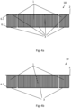
- Fig. 2a shows a filter 10 according to the invention in a first view.
- the filter 10 has three bellows 1 made of pleated filter medium 7, wherein the bellows 1 are flowed through by separate air streams F1, F2 and F3, respectively.
- the bellows 1 have first and second side surfaces 6.1, 6.2. On their first side surfaces 6.1, the bellows 1 are provided with a continuous band 2 and on their second side surfaces 6.2 with a segmented edge band 3. On their first side surfaces 6.1, the bellows 1 can alternatively be provided with a segmented edge band 3, so that three filter elements are present (not shown here, see. Fig. 4a ). Each segment of the segmented edge band 3 is not directly connected to the other segments and extends only to the side surface 6.1, 6.2 of the respective bellows 1.
- the three bellows 1 all have convex outward-curving end folds 5.
- Fig. 2b shows a filter 10 in a second view.
- the three air streams F1, F2, F3 flow through the filter from an inflow side AN to an outflow side AB.
- edges 5.1 of the filter medium 7 of all end folds 5 are all oriented towards one side, here namely the inflow side AN of the filter 10.
- Fig.3 shows a filter arrangement 100 in a roughly schematic sectional view.
- the filter arrangement 100 has a filter 10 as shown in the Fig. 2a and b.
- This filter 10 is accommodated in a filter housing 9.
- the filter 1 can be inserted into the housing 9 in the assembly direction M.
- the filter housing 9 has three compartments 9.1, 9.2, 9.3, which are separated from one another by partition walls.
- Each bellows 1 is assigned a compartment 9.1, 9.2, 9.3.
- the bellows 1 are arranged at a distance from one another and there is a gap 8 between each two bellows 1. Partition walls of a housing 9 can engage in this gap 8.
- the two walls between the compartments 9.1, 9.2, 9.3 engage in the two Column 8.
- the width of column 8 corresponds approximately to the width of the walls and the end folds 5 each rest against the housing 9.
- Fig. 4a shows a variant with three filter elements, which form a filter 10.
- Each filter element has a bellows 1, which is provided with a segmented edge band 3 on its first side surface 6.1 and on its second side surface 6.2.
- the edge band 3 can be glued onto the bellows 1.
- the filter elements are additionally provided with a continuous band 2, which can also be glued on and connects the filter elements to one another.
- Fig. 4b shows a variant with three bellows 1 which form a filter 10.
- Each bellows 1 is provided with a segmented edge band 3 on its second side surface 6.2.
- the edge band 3 can be glued onto the bellows 1.
- the bellows 1 are additionally provided with a continuous band 2, which can also be glued on and connects the bellows 1 to one another.
Landscapes
- Chemical & Material Sciences (AREA)
- Chemical Kinetics & Catalysis (AREA)
- Filtering Of Dispersed Particles In Gases (AREA)
Abstract
Description
- Die Erfindung betrifft einen Filter mit mindestens zwei Faltenbalgen oder Filterelemente mit Faltenbalgen aus plissiertem Filtermedium, wobei die Faltenbalge erste und zweite Seitenflächen aufweisen, wobei die Faltenbalge an ihren Seitenflächen mit Kantenbändern versehen sind.
- Aus dem Stand der Technik sind zahlreiche Lösungen zur Fitration von Fluidströmen bekannt. Häufig kommen dabei plissierte Filtermedien zum Einsatz. Die
EP 3 332 858 A1 zeigt ein Filterelement mit einem mit Falten versehenen Filtermedium, welches also plissiert ist, und einen Faltenbalg bildet. An seinen seitlichen Flächen ist der Faltenbalg mit einem Kantenband versehen. Das Filterelement kann in einen Rahmen eingesetzt werden, welcher häufig aus Kunststoff hergestellt ist, um eine sichere kraft- bzw. reibschlüssige Abdichtung zwischen Filterelement und Rahmen zu gewährleisten. Alternativ zu einem Rahmen kann auch ein Gehäuse das Filterelement aufnehmen. - Wie in der
DE 10 2009 041 113 A1 gezeigt, können von den Kantenbändern Laschen abragen, welche die Abdichtung zum Gehäuse verbessern. - Wie in der
DE 10 2019 102 104 A1 können die Endfalten des Faltenbalgs als konvexe, nach außen gewölbte Endfalten ausgebildet sein, welche die Abdichtung zum Gehäuse verbessern. - Aufgabe der vorliegenden Erfindung ist es, einen Filter zu schaffen, welcher in einem Gehäuse mit mehreren Kammern zur Filtration verschiedener Luftströme verwendet werden kann.
- Weitere Aufgabe ist es eine Filteranordnung zu schaffen, welche ein Gehäuse mit mehreren Kammern und einen passenden Filter zur Filtration verschiedener Luftströme aufweist.
- Gelöst wird diese Aufgabe durch einen Filter mit einem durchgehenden und mit einem segmentierten Kantenstreifen.
- Erfindungsgemäß wurde als vorteilhaft erkannt mehrerer Faltenbalge oder mehrere Filterelemente zu einem Filter zusammenzufassen, sodass der Filter ein Bauteil darstellt. Ein solcher Filter kann in einem Arbeitsschritt besonders schnell und einfach in ein aufnehmendes Filtergehäuse montiert werden. Unter einem Filterelement wird hier ein mit an seinen beiden Seitenflächen versehener Faltenbalg verstanden.
- Der erfindungsgemäße Filter dient der Filtration mehrerer Luftströme und wird zur Reinigung der Luftströme von einer Anströmseite zu einer Abströmseite des Filters hin durchströmt. Der Filter weist mindestens zwei Faltenbalge oder mindestens zwei Filterelemente mit je einem Faltenbalg auf, welche von einem plissierten, d.h. mit Falten versehenen Filtermedium gebildet werden. Die Faltenbalge weisen erste und zweite Seitenflächen auf. Bei den Seitenflächen handelt es sich um die sich nicht in Richtung der Faltkanten erstreckenden Seitenflächen des Faltenbalgs, welche durch die zickzack-förmigen Kanten des Filtermediums gebildet werden und somit an den Enden der Faltkanten positioniert sind. Die Faltenbalge sind an ihren ersten Seitenflächen mit einem durchgehenden Band versehen und miteinander verbunden. Werden Filterelemente verwendet, so sind diese an ihrer ersten Seitenfläche zusätzlich mit einem segmentierten Kantenband versehen. Das segmentierte Kantenband ist zwischen Faltenbalg und durchgehendem Band angeordnet. Ein jeweiliges segmentiertes Kantenband ist dabei einem jeweiligen Filterelement und dessen Faltenbalg zugeordnet. An ihren zweiten Seitenflächen sind die Faltenbalge mit einem segmentierten Kantenband versehen. Das segmentierte Kantenband weist dabei so viele Segmente auf, wie Faltenbalge vorhanden sind. An einem jeweiligen Faltenbalg ist an dessen zweiter Seitenfläche also ein Segment des segmentierten Kantenbandes angebracht. An den zweiten Seitenflächen sind die Faltenbalge folglich nicht miteinander verbunden. Mit Ausnahme des durchgehenden Bandes bzw. Kantenbandes ist also auch der Filter als Ganzes segmentiert bzw. unterteilt.
- Im Falle der Verwendung von mindestens zwei Faltenbalgen an Stelle von mindestens zwei Filterelementen kann das durchgehende Band als durchgehendes Kantenband ausgeführt sein.
- Alternative Begriffe für "Kantenband" sind auch "Seitenstreifen" oder "Kantenstreifen". Das Kantenband ist ein Band bzw. Streifen aus einem flächigen Material.
- Solche Kantenbänder dienen zum einen der Stabilisierung der Faltenbalge und des Filterelements. Zum anderen kann durch die Kantenbänder eine Abdichtung der Seitenflächen der Faltenbalge gegenüber angrenzenden Flächen einer Filteraufnahme erreicht werden. Die Kantenbänder können entweder nur an den beiden Seitenflächen angebracht sein. Alternativ können die Kantenbänder auch an den weiteren Flächen im Bereich der Endfalten angebracht sein.
- In der ersten Variante werden mehrere Faltenbalge zu einem Filter zusammengefasst. In der zweiten Variante werden mehrere Filterelemente, d.h. mehrere bereits mit Kantenbändern versehene Faltenbalge zu einem Filter zusammengefasst.
- In einer konkreten Ausführungsform kann der Filter drei Faltenbalge oder drei Filterelemente aufweisen. Es ist jedoch auch eine größere Anzahl an Faltenbalgen oder Filterelementen denkbar.
- Alle Faltenbalge können in vorteilhafter Weise derart ausgestaltet sein, dass jede Endfalte, auch als Faltenauslauf bezeichnet, d.h. ein letzter Faltabschnitt, konvex nach außen gewölbt ist, d.h., es liegt eine Wölbung an der Stirnseite des Faltenbalgs vor. Es wurde überraschend festgestellt, dass bei einer derartigen Ausgestaltung des Filters ein hoher Anpressdruck auf die konvex nach außen gewölbte Endfalten bei Anliegen eines Volumenstroms an dem Filter bewirkt wird. Wird der erfindungsgemäße Filter in eine Filteraufnahme eingesetzt, beispielsweise in einen Filterrahmen oder in ein Filtergehäuse, und kommen die konvex nach außen gewölbten Endfalten zur Anlage an einer Wand der Filteraufnahme, so wird aufgrund des hohen Anpressdrucks eine gute Abdichtwirkung erzielt und Bypässe im Bereich der konvex nach außen gewölbten Endfalten können vermieden oder zumindest stark reduziert werden.
- In besonders vorteilhafter Weiterbildung des Filters sind die Kanten des Filtermediums aller Endfalten, welche sich parallel zu den Faltkanten erstrecken, alle zu einer Seite des Filterelements hin orientiert, also entweder zur Anströmseite oder zur Abströmseite. Bevorzugt ist die Orientierung hin zur Anströmseite, da dann die zuvor beschriebene leckagearme bzw. leckagefreie Anlage der konvexen Endfalten ermöglicht wird.
- In vorteilhafter Ausgestaltung ist am durchgehenden Band und/oder am segmentierten Kantenband mindestens eine Lasche angebracht ist. Die Lasche kann als Dichtungslasche ausgebildet sein und / oder als Auszugslasche.
- Die Dichtungslasche kann am durchgehenden Band und/oder am segmentierten Kantenband angebracht sein und eine bessere Abdichtung zum Gehäuse bewirken. Die Auszugslasche kann am durchgehenden Band angebracht sein und ein einfacheres Ergreifen und Demontieren des Filters ermöglichen.
- Die mindestens eine Lasche kann aus demselben Material sein, wie auch das Band oder das Kantenband. Auch eine einteilige Ausgestaltung der Lasche mit dem Band bzw. Kantenband ist denkbar. Diese Varianten sind aus fertigungstechnischer Hinsicht besonders vorteilhaft.
- Besonders vorteilhaft ist es, wenn der Faltenbalg aus Vliesstoff gebildet wird, da Vliesstoff ein leichtes Material mit guten Filter- und Fertigungseigenschaften darstellt. Auch das durchgehende Band und die Kantenbänder können aus einem Vliesstoff gefertigt sein.
- Um das durchgehende Band an den Filterelementen und die Kantenbänder an den Faltenbalgen zu befestigen, können diese miteinander verklebt sein, beispielsweise mit einem Hotmeltklebstoff.
- Die Erfindung betrifft auch eine Filteranordnung mit einem Filter wie vorstehend beschrieben und mit einem Filtergehäuse zur Aufnahme des Filters. Das Filtergehäuse besitzt eine Mehrzahl von Fächern, wobei jedem Faltenbalg bzw. jedem Filterelement je ein Fach zugeordnet ist und ein jeweiliger Faltenbalg bzw. ein jeweiliges Filterelement in einem jeweiligen Fach aufgenommen ist. Anstelle von Fächern können auch Kammern bzw. Schächte vorgesehen werden. Unabhängig von der Begrifflichkeit und der konkreten geometrischen Ausgestaltung ist Fächern, Kammern und Schächten gemein, dass sie durch Wände oder Stege voneinander getrennt sind. Die sich in den Fächern, Kammern bzw. Schächten befindliche Faltenbalge oder Filterelemente können von unterschiedlichen Luftströmen durchströmt und dabei gereinigt werden.
- Der Filter wird dabei in vorteilhafter Weise so eingesetzt, dass die Kanten des Filtermediums der Endfalten auf der Anströmseite des Filterelements liegen. Dadurch wird eine besonders gute Abdichtung der Faltenbalge zu den Fächern an den Endfalten erreicht und Leckage vermieden.
- In vorteilhafter Ausgestaltung sind die Faltenbalge in montiertem Zustand beabstandet zueinander, d.h. die Endfalten liegen nicht flächig aneinander an sondern es gibt einen Spalt zwischen je zwei aneinander angrenzenden Baltenbalgen und deren Segmenten des segmentierten Kantenbandes. Es handelt sich dabei um einen Spalt kleiner Breite, insbesondere im Bereiche 0,1 bis 10 Millimeter. In diesen Spalt greifen Wände bzw. Stege von Fächern, Kammern bzw. Schächten des Filtergehäuses ein.
- Die erfindungsgemäße Filteranordnung kann insbesondere als Innenraum-Luftfilter in Fahrzeugen, wie z.B. Autos, PKW, NKW, Bussen, Zügen oder Schiffen oder deren Klimaanlagen verwendet werden.
- Hinsichtlich weiterer Vorteile und in konstruktiver und funktioneller Hinsicht vorteilhafter Ausgestaltungen der Erfindung wird auf die Unteransprüche sowie die Beschreibung von Ausführungsbeispielen unter Bezugnahme auf die beiliegenden Figuren verwiesen.
- Die beschriebene Erfindung und die beschriebenen vorteilhaften Weiterbildungen der Erfindung stellen auch in Kombination miteinander - soweit dies technisch sinnvoll ist - vorteilhafte Weiterbildungen der Erfindung dar.
- Die Erfindung soll anhand beigefügter Figuren noch näher erläutert werden. Einander entsprechende Elemente und Bauteile sind in den Figuren mit gleichen Bezugszeichen versehen. Zugunsten einer besseren Übersichtlichkeit der Figuren wurde auf eine maßstabsgetreue Darstellung verzichtet.
- Es zeigen in schematischer Darstellung
- Fig. 1
- einen Filter gemäß dem Stand der Technik
- Fig. 2a
- einen Filter in einer ersten Ansicht
- Fig. 2b
- einen Filter in einer zweiten Ansicht
- Fig. 3
- eine Filteranordnung in einer grobschematischen Schnittdarstellung
- Fig. 4a
- eine Variante mit drei Filterelementen
- Fig. 4b
- eine Variante mit drei Faltenbalgen
-
Fig. 1 zeigt einen Filter 10 mit einem Faltenbalg 11 gemäß dem Stand der Technik. Der Faltenbalg 11 wird durch ein mit Falten versehenes, plissiertes Filtermedium 7 gebildet und besitzt zwei Endfalten 14. Durch das Vorsehen der Vielzahl von Falten kann die Filtrationsfläche des Filters 10 vergrößert werden. An seinen beiden sich nicht in Richtung der Falten erstreckenden Seitenflächen 16 ist der Filter 10 mit jeweils einem Kantenband 12 versehen. Ein solcher Filter 10 kann in ein hier nicht dargestelltes Gehäuse 9 eingesetzt werden. Zur Reinigung eines Fluids strömt dieses in Durchströmungsrichtung L durch das Filtermedium 7 des Filters 10. -
Fig. 2a zeigt einen erfindungsgemäßen Filter 10 in einer ersten Ansicht. Der Filter 10 besitzt drei Faltenbalge 1 aus plissiertem Filtermedium 7, wobei die Faltenbalge 1 von getrennten Luftströmen F1, F2 bzw. F3 durchströmt werden. - Die Faltenbalge 1 weisen erste und zweite Seitenflächen 6.1, 6.2 auf. An ihren ersten Seitenflächen 6.1 sind die Faltenbalge 1 mit einem durchgehenden Band 2 versehen und an ihren zweiten Seitenflächen 6.2 mit einem segmentierten Kantenband 3. An ihren ersten Seitenflächen 6.1 können die Faltenbalge 1 alternativ mit einem segmentierten Kantenband 3 versehen sein, sodass drei Filterelemente vorliegen (hier nicht dargestellt, vgl.
Fig. 4a ). Ein jeweiliges Segment des segmentierten Kantenbandes 3 ist mit den anderen Segmenten nicht direkt verbunden und erstreckt sich nur auf die Seitenfläche 6.1, 6.2 des jeweiligen Faltenbalgs 1. - Die drei Faltenbalge 1 besitzen alle konvex nach außen gewölbte Endfalten 5.
-
Fig. 2b zeigt einen Filter 10 in einer zweiten Ansicht. Die drei Luftströme F1, F2, F3 durchströmen den Filter von einer Anströmseite AN zu einer Abströmseite AB. - Die Kanten 5.1 des Filtermediums 7 aller Endfalten 5 sind alle zu einer Seite hin orientiert, hier nämlich der Anströmseite AN des Filters 10.
-
Fig. 3 zeigt eine Filteranordnung 100 in einer grobschematischen Schnittdarstellung. - Die Filteranordnung 100 besitzt einen Filter 10 wie er in den
Fig. 2a und b dargestellt ist. Dieser Filter 10 wird in einem Filtergehäuse 9 aufgenommen. Dazu kann der Filter 1 in Montagerichtung M in das Gehäuse 9 eingeführt werden. Das Filtergehäuse 9 weist drei Fächer 9.1, 9.2, 9.3 auf, welche durch Trennwände voneinander getrennt werden. Jedem Faltenbalg 1 ist dabei je ein Fach 9.1, 9.2, 9.3 zugeordnet. Die Faltenbalge 1 sind beabstandet zueinander angeordnet und es gibt zwischen je zwei Faltenbalgen 1 einen Spalt 8. In diese Spalte 8 können Trennwände eines Gehäuses 9 eingreifen Bei der Montage des Filters 1 in das Gehäuse 9 und beim Einschieben in Montagerichtung M greifen die beiden Wände zwischen den Fächern 9.1, 9.2, 9.3 in die beiden Spalte 8 ein. In eingebautem Zustand entspricht die Breite der Spalte 8 in etwa der Breite der Wände und die Endfalten 5 liegen jeweils an dem Gehäuse 9 an. -
Fig. 4a zeigt eine Variante mit drei Filterelementen, welche einen Filter 10 bilden. Ein jeweiliges Filterelement besitzt dabei einen Faltenbalg 1, welcher an seiner ersten Seitenfläche 6.1 und an seiner zweiten Seitenfläche 6.2 jeweils mit einem segmentierten Kantenband 3 versehen ist. Das Kantenband 3 kann auf den Faltenbalg 1 aufgeklebt sein. An ihrer ersten Seitenfläche 6.1 sind die Filterelemente zusätzlich mit einem durchgehenden Band 2 versehen, welches ebenfalls aufgeklebt sein kann und die Filterelemente miteinander verbindet. -
Fig. 4b zeigt eine Variante mit drei Faltenbalgen 1 welche einen Filter 10 bilden. Ein jeweiliger Faltenbalg 1 ist an seiner zweiten Seitenfläche 6.2 mit einem segmentierten Kantenband 3 versehen ist. Das Kantenband 3 kann auf den Faltenbalg 1 aufgeklebt sein. An ihren ersten Seitenflächen 6.1 sind die Faltenbalge 1 zusätzlich mit einem durchgehenden Band 2 versehen, welches ebenfalls aufgeklebt sein kann und die Faltenbalge 1 miteinander verbindet. -
- 1
- Faltenbalg
- 2
- durchgehendes Band, z.B. Kantenband
- 2.1
- Lasche
- 3
- segmentiertes Kantenband
- 4
- Endfalte
- 5
- konvexe Endfalte
- 5.1
- Kante der Endfalte
- 6.1
- erste Seitenfläche des Faltenbalgs
- 6.2
- zweite Seitenfläche des Faltenbalgs
- 7
- Filtermedium
- 8
- Spalt
- 9
- Filteraufnahme (Gehäuse mit drei Fächern)
- 9.1, 9.2, 9.3
- Fächer der Filteraufnahme
- 10
- Filter
- 11
- Faltenbalg
- 12
- Kantenband
- 14
- Endfalte
- 16
- Seitenfläche des Faltenbalgs
- 100
- Filteranordnung
- AN
- Anströmseite
- AB
- Abströmseite
- F1, F2, F3
- Luftströme
- L
- Durchströmungsrichtung
- M
- Einschubrichtung bei Montage
Claims (6)
- Filter (10) mit mindestens zwei Filterelementen mit Faltenbalgen (1) oder mit mindestens zwei Faltenbalgen (1), wobei die Faltenbalge (1) aus plissiertem Filtermedium (7) sind und erste und zweite Seitenflächen (6.1, 6.2) aufweisen, wobei die Filterelemente oder Faltenbalge (1) an ihren ersten Seitenflächen (6.1) mit einem durchgehenden Band (2) versehen und die Faltenbalge (1) an ihren zweiten Seitenflächen (6.2) mit einem segmentierten Kantenband (3) versehen sind.
- Filter nach Anspruch 1 dadurch gekennzeichnet, dass die Faltenbalge (1) konvex nach außen gewölbte Endfalten (5) besitzen.
- Filter nach Anspruch 2 dadurch gekennzeichnet, dass die Kanten (5.1) des Filtermediums (7) aller Endfalten (5) zu einer Seite (AN, AB) des Filters (10) hin orientiert sind.
- Filter nach einem der vorangehenden Ansprüche dadurch gekennzeichnet, dass am durchgehenden Band (2) und/oder am segmentierten Kantenband (3) mindestens eine Lasche (2) angebracht ist.
- Filteranordnung (100) mit einem Filter (10) nach einem der vorangehenden Ansprüche und einem Filtergehäuse (9) zur Aufnahme des Filters (10), wobei das Filtergehäuse (9) eine Mehrzahl von Fächern (9.1, 9.2, 9.3) besitzt, wobei jedem Faltenbalg (1) je ein Fach (9.1, 9.2, 9.3) zugeordnet ist.
- Filteranordnung nach Anspruch 5 dadurch gekennzeichnet, dass die Faltenbalge (1) beabstandet zueinander sind.
Priority Applications (2)
| Application Number | Priority Date | Filing Date | Title |
|---|---|---|---|
| EP23159688.3A EP4424401B1 (de) | 2023-03-02 | 2023-03-02 | Filteranornung mit filter mit segmentiertem kantenband |
| DE102023123890.6A DE102023123890A1 (de) | 2023-03-02 | 2023-09-05 | Filter mit segmentiertem Kantenband und Filteranordnung |
Applications Claiming Priority (1)
| Application Number | Priority Date | Filing Date | Title |
|---|---|---|---|
| EP23159688.3A EP4424401B1 (de) | 2023-03-02 | 2023-03-02 | Filteranornung mit filter mit segmentiertem kantenband |
Publications (2)
| Publication Number | Publication Date |
|---|---|
| EP4424401A1 true EP4424401A1 (de) | 2024-09-04 |
| EP4424401B1 EP4424401B1 (de) | 2025-10-08 |
Family
ID=85462184
Family Applications (1)
| Application Number | Title | Priority Date | Filing Date |
|---|---|---|---|
| EP23159688.3A Active EP4424401B1 (de) | 2023-03-02 | 2023-03-02 | Filteranornung mit filter mit segmentiertem kantenband |
Country Status (2)
| Country | Link |
|---|---|
| EP (1) | EP4424401B1 (de) |
| DE (1) | DE102023123890A1 (de) |
Families Citing this family (1)
| Publication number | Priority date | Publication date | Assignee | Title |
|---|---|---|---|---|
| DE102024206186A1 (de) * | 2024-07-02 | 2026-01-08 | BSH Hausgeräte GmbH | Geruchsfiltereinheit für Dunstabzugsvorrichtung |
Citations (10)
| Publication number | Priority date | Publication date | Assignee | Title |
|---|---|---|---|---|
| DE3834942A1 (de) * | 1987-10-14 | 1989-04-27 | Nippon Denso Co | Filtervorrichtung |
| JP2005007361A (ja) * | 2003-06-20 | 2005-01-13 | Denso Corp | エアフィルタ |
| DE102007057616A1 (de) * | 2007-11-30 | 2009-06-04 | Helsa-Automotive Gmbh & Co. Kg | Filtereinsatz und Filtereinrichtung |
| DE102009019859A1 (de) * | 2008-05-07 | 2009-12-03 | Mann + Hummel Gmbh | Filterelement |
| DE102009041113A1 (de) | 2009-09-15 | 2011-03-24 | Carl Freudenberg Kg | Filteranordnung mit einrastbaren V-Laschen |
| DE102015004336A1 (de) * | 2015-04-09 | 2016-10-13 | Mann + Hummel Gmbh | Filterelement mit Lasche und Filtersystem |
| EP3332858A1 (de) | 2016-12-07 | 2018-06-13 | Carl Freudenberg KG | Filterelement |
| DE102017212383A1 (de) * | 2017-07-19 | 2019-01-24 | Mahle International Gmbh | Filterelement für einen Fahrgastinnenraum eines Kraftfahrzeugs |
| DE102019102104A1 (de) | 2019-01-29 | 2020-07-30 | Carl Freudenberg Kg | Filterelement, Filteranordnung mit einem solchen Filterelement und Verwendung der Filteranordnung |
| EP4011480A1 (de) * | 2020-12-09 | 2022-06-15 | Carl Freudenberg KG | Klappbare filteranordnung bestehend aus mehreren einzelfilterelementen |
-
2023
- 2023-03-02 EP EP23159688.3A patent/EP4424401B1/de active Active
- 2023-09-05 DE DE102023123890.6A patent/DE102023123890A1/de active Pending
Patent Citations (10)
| Publication number | Priority date | Publication date | Assignee | Title |
|---|---|---|---|---|
| DE3834942A1 (de) * | 1987-10-14 | 1989-04-27 | Nippon Denso Co | Filtervorrichtung |
| JP2005007361A (ja) * | 2003-06-20 | 2005-01-13 | Denso Corp | エアフィルタ |
| DE102007057616A1 (de) * | 2007-11-30 | 2009-06-04 | Helsa-Automotive Gmbh & Co. Kg | Filtereinsatz und Filtereinrichtung |
| DE102009019859A1 (de) * | 2008-05-07 | 2009-12-03 | Mann + Hummel Gmbh | Filterelement |
| DE102009041113A1 (de) | 2009-09-15 | 2011-03-24 | Carl Freudenberg Kg | Filteranordnung mit einrastbaren V-Laschen |
| DE102015004336A1 (de) * | 2015-04-09 | 2016-10-13 | Mann + Hummel Gmbh | Filterelement mit Lasche und Filtersystem |
| EP3332858A1 (de) | 2016-12-07 | 2018-06-13 | Carl Freudenberg KG | Filterelement |
| DE102017212383A1 (de) * | 2017-07-19 | 2019-01-24 | Mahle International Gmbh | Filterelement für einen Fahrgastinnenraum eines Kraftfahrzeugs |
| DE102019102104A1 (de) | 2019-01-29 | 2020-07-30 | Carl Freudenberg Kg | Filterelement, Filteranordnung mit einem solchen Filterelement und Verwendung der Filteranordnung |
| EP4011480A1 (de) * | 2020-12-09 | 2022-06-15 | Carl Freudenberg KG | Klappbare filteranordnung bestehend aus mehreren einzelfilterelementen |
Also Published As
| Publication number | Publication date |
|---|---|
| DE102023123890A1 (de) | 2023-11-09 |
| EP4424401B1 (de) | 2025-10-08 |
Similar Documents
| Publication | Publication Date | Title |
|---|---|---|
| DE102009040202B4 (de) | Filter | |
| EP1134014B2 (de) | Filtereinsatz | |
| DE69706551T3 (de) | Filtervorrichtung zum filtrieren eines fluids | |
| EP2135662B2 (de) | Komprimierbares Filterelement mit zueinander geneigten Endkappen | |
| EP2094370B2 (de) | Filtermodul mit einem kompressiblen und selbstausdehnenden filterelement, und verfahren | |
| EP1736227B1 (de) | Filterdichtsystem | |
| EP3680003B1 (de) | Filterpatrone mit venturi-düse | |
| EP4424401B1 (de) | Filteranornung mit filter mit segmentiertem kantenband | |
| DE102017219009A1 (de) | Filterverbund zum Verbau in einem Fahrzeug | |
| EP3093058A1 (de) | Filterelement für eine filtereinrichtung | |
| EP3077078A1 (de) | Filterelement mit filterbalg | |
| DE102014008704B3 (de) | Filter mit einem schräg durchströmten Filterelement | |
| DE102014219403A1 (de) | Filterelement zum Filtern von Fluid mit einem gefalteten Filtermaterial | |
| EP3744414A1 (de) | Filter mit umgefaltetem kantenband | |
| DE10241748B4 (de) | Filterelement | |
| DE102007035967A1 (de) | Rückspüleinrichtung für eine Filteranlage | |
| DE102024128052A1 (de) | Filterelement und Filtersystem | |
| EP4011480B1 (de) | Klappbare filteranordnung bestehend aus mehreren einzelfilterelementen | |
| EP2078554B1 (de) | Filtereinrichtung zur Filtration gasförmiger Fluide | |
| DE102017000111A1 (de) | Filterelement mit Zusatzbauteil und Filtersystem | |
| DE102015218088A1 (de) | Filtereinrichtung | |
| DE202019104501U1 (de) | Filtereinrichtung für ein Kraftfahrzeug | |
| DE10235122B3 (de) | Flexibler Filter | |
| DE102018202718A1 (de) | Ringdichtung aus elastischem Kunststoff | |
| DE102019102104A1 (de) | Filterelement, Filteranordnung mit einem solchen Filterelement und Verwendung der Filteranordnung |
Legal Events
| Date | Code | Title | Description |
|---|---|---|---|
| PUAI | Public reference made under article 153(3) epc to a published international application that has entered the european phase |
Free format text: ORIGINAL CODE: 0009012 |
|
| STAA | Information on the status of an ep patent application or granted ep patent |
Free format text: STATUS: THE APPLICATION HAS BEEN PUBLISHED |
|
| AK | Designated contracting states |
Kind code of ref document: A1 Designated state(s): AL AT BE BG CH CY CZ DE DK EE ES FI FR GB GR HR HU IE IS IT LI LT LU LV MC ME MK MT NL NO PL PT RO RS SE SI SK SM TR |
|
| STAA | Information on the status of an ep patent application or granted ep patent |
Free format text: STATUS: REQUEST FOR EXAMINATION WAS MADE |
|
| 17P | Request for examination filed |
Effective date: 20250227 |
|
| GRAP | Despatch of communication of intention to grant a patent |
Free format text: ORIGINAL CODE: EPIDOSNIGR1 |
|
| STAA | Information on the status of an ep patent application or granted ep patent |
Free format text: STATUS: GRANT OF PATENT IS INTENDED |
|
| RIC1 | Information provided on ipc code assigned before grant |
Ipc: B01D 46/52 20060101ALI20250414BHEP Ipc: B01D 46/58 20220101ALI20250414BHEP Ipc: B01D 46/12 20220101ALI20250414BHEP Ipc: B01D 46/10 20060101ALI20250414BHEP Ipc: B01D 46/00 20220101AFI20250414BHEP |
|
| INTG | Intention to grant announced |
Effective date: 20250507 |
|
| P01 | Opt-out of the competence of the unified patent court (upc) registered |
Free format text: CASE NUMBER: APP_28589/2025 Effective date: 20250616 |
|
| GRAS | Grant fee paid |
Free format text: ORIGINAL CODE: EPIDOSNIGR3 |
|
| GRAA | (expected) grant |
Free format text: ORIGINAL CODE: 0009210 |
|
| STAA | Information on the status of an ep patent application or granted ep patent |
Free format text: STATUS: THE PATENT HAS BEEN GRANTED |
|
| AK | Designated contracting states |
Kind code of ref document: B1 Designated state(s): AL AT BE BG CH CY CZ DE DK EE ES FI FR GB GR HR HU IE IS IT LI LT LU LV MC ME MK MT NL NO PL PT RO RS SE SI SK SM TR |
|
| REG | Reference to a national code |
Ref country code: GB Ref legal event code: FG4D Free format text: NOT ENGLISH Ref country code: CH Ref legal event code: F10 Free format text: ST27 STATUS EVENT CODE: U-0-0-F10-F00 (AS PROVIDED BY THE NATIONAL OFFICE) Effective date: 20251008 |
|
| REG | Reference to a national code |
Ref country code: DE Ref legal event code: R096 Ref document number: 502023001924 Country of ref document: DE |
|
| REG | Reference to a national code |
Ref country code: IE Ref legal event code: FG4D Free format text: LANGUAGE OF EP DOCUMENT: GERMAN |
|
| REG | Reference to a national code |
Ref country code: NL Ref legal event code: MP Effective date: 20251008 |
|
| PG25 | Lapsed in a contracting state [announced via postgrant information from national office to epo] |
Ref country code: NL Free format text: LAPSE BECAUSE OF FAILURE TO SUBMIT A TRANSLATION OF THE DESCRIPTION OR TO PAY THE FEE WITHIN THE PRESCRIBED TIME-LIMIT Effective date: 20251008 |
|
| PG25 | Lapsed in a contracting state [announced via postgrant information from national office to epo] |
Ref country code: ES Free format text: LAPSE BECAUSE OF FAILURE TO SUBMIT A TRANSLATION OF THE DESCRIPTION OR TO PAY THE FEE WITHIN THE PRESCRIBED TIME-LIMIT Effective date: 20251008 |
|
| REG | Reference to a national code |
Ref country code: LT Ref legal event code: MG9D |
|
| PG25 | Lapsed in a contracting state [announced via postgrant information from national office to epo] |
Ref country code: NO Free format text: LAPSE BECAUSE OF FAILURE TO SUBMIT A TRANSLATION OF THE DESCRIPTION OR TO PAY THE FEE WITHIN THE PRESCRIBED TIME-LIMIT Effective date: 20260108 |
|
| PGFP | Annual fee paid to national office [announced via postgrant information from national office to epo] |
Ref country code: DE Payment date: 20260320 Year of fee payment: 4 |
|
| PG25 | Lapsed in a contracting state [announced via postgrant information from national office to epo] |
Ref country code: HR Free format text: LAPSE BECAUSE OF FAILURE TO SUBMIT A TRANSLATION OF THE DESCRIPTION OR TO PAY THE FEE WITHIN THE PRESCRIBED TIME-LIMIT Effective date: 20251008 Ref country code: FI Free format text: LAPSE BECAUSE OF FAILURE TO SUBMIT A TRANSLATION OF THE DESCRIPTION OR TO PAY THE FEE WITHIN THE PRESCRIBED TIME-LIMIT Effective date: 20251008 |
|
| PGFP | Annual fee paid to national office [announced via postgrant information from national office to epo] |
Ref country code: AT Payment date: 20260301 Year of fee payment: 4 |
|
| PG25 | Lapsed in a contracting state [announced via postgrant information from national office to epo] |
Ref country code: RS Free format text: LAPSE BECAUSE OF FAILURE TO SUBMIT A TRANSLATION OF THE DESCRIPTION OR TO PAY THE FEE WITHIN THE PRESCRIBED TIME-LIMIT Effective date: 20260108 |
|
| PG25 | Lapsed in a contracting state [announced via postgrant information from national office to epo] |
Ref country code: IS Free format text: LAPSE BECAUSE OF FAILURE TO SUBMIT A TRANSLATION OF THE DESCRIPTION OR TO PAY THE FEE WITHIN THE PRESCRIBED TIME-LIMIT Effective date: 20260208 |
|
| PG25 | Lapsed in a contracting state [announced via postgrant information from national office to epo] |
Ref country code: PT Free format text: LAPSE BECAUSE OF FAILURE TO SUBMIT A TRANSLATION OF THE DESCRIPTION OR TO PAY THE FEE WITHIN THE PRESCRIBED TIME-LIMIT Effective date: 20260209 |
|
| PG25 | Lapsed in a contracting state [announced via postgrant information from national office to epo] |
Ref country code: PL Free format text: LAPSE BECAUSE OF FAILURE TO SUBMIT A TRANSLATION OF THE DESCRIPTION OR TO PAY THE FEE WITHIN THE PRESCRIBED TIME-LIMIT Effective date: 20251008 |
|
| PG25 | Lapsed in a contracting state [announced via postgrant information from national office to epo] |
Ref country code: LV Free format text: LAPSE BECAUSE OF FAILURE TO SUBMIT A TRANSLATION OF THE DESCRIPTION OR TO PAY THE FEE WITHIN THE PRESCRIBED TIME-LIMIT Effective date: 20251008 |
|
| PG25 | Lapsed in a contracting state [announced via postgrant information from national office to epo] |
Ref country code: BG Free format text: LAPSE BECAUSE OF FAILURE TO SUBMIT A TRANSLATION OF THE DESCRIPTION OR TO PAY THE FEE WITHIN THE PRESCRIBED TIME-LIMIT Effective date: 20251008 |