EP4424352A2 - Lenkbare medizinische vorrichtung mit geflochtener struktur und herstellungsverfahren dafür - Google Patents
Lenkbare medizinische vorrichtung mit geflochtener struktur und herstellungsverfahren dafür Download PDFInfo
- Publication number
- EP4424352A2 EP4424352A2 EP24181489.6A EP24181489A EP4424352A2 EP 4424352 A2 EP4424352 A2 EP 4424352A2 EP 24181489 A EP24181489 A EP 24181489A EP 4424352 A2 EP4424352 A2 EP 4424352A2
- Authority
- EP
- European Patent Office
- Prior art keywords
- medical device
- polymer electrolyte
- electrodes
- distal end
- electrolyte layer
- Prior art date
- Legal status (The legal status is an assumption and is not a legal conclusion. Google has not performed a legal analysis and makes no representation as to the accuracy of the status listed.)
- Pending
Links
Images


Classifications
-
- A—HUMAN NECESSITIES
- A61—MEDICAL OR VETERINARY SCIENCE; HYGIENE
- A61B—DIAGNOSIS; SURGERY; IDENTIFICATION
- A61B1/00—Instruments for performing medical examinations of the interior of cavities or tubes of the body by visual or photographical inspection, e.g. endoscopes; Illuminating arrangements therefor
- A61B1/00064—Constructional details of the endoscope body
- A61B1/0011—Manufacturing of endoscope parts
-
- A—HUMAN NECESSITIES
- A61—MEDICAL OR VETERINARY SCIENCE; HYGIENE
- A61B—DIAGNOSIS; SURGERY; IDENTIFICATION
- A61B1/00—Instruments for performing medical examinations of the interior of cavities or tubes of the body by visual or photographical inspection, e.g. endoscopes; Illuminating arrangements therefor
- A61B1/005—Flexible endoscopes
- A61B1/0051—Flexible endoscopes with controlled bending of insertion part
- A61B1/0052—Constructional details of control elements, e.g. handles
- A61B1/0053—Constructional details of control elements, e.g. handles using distributed actuators, e.g. artificial muscles
-
- A—HUMAN NECESSITIES
- A61—MEDICAL OR VETERINARY SCIENCE; HYGIENE
- A61L—METHODS OR APPARATUS FOR STERILISING MATERIALS OR OBJECTS IN GENERAL; DISINFECTION, STERILISATION OR DEODORISATION OF AIR; CHEMICAL ASPECTS OF BANDAGES, DRESSINGS, ABSORBENT PADS OR SURGICAL ARTICLES; MATERIALS FOR BANDAGES, DRESSINGS, ABSORBENT PADS OR SURGICAL ARTICLES
- A61L29/00—Materials for catheters, medical tubing, cannulae, or endoscopes or for coating catheters
- A61L29/02—Inorganic materials
-
- A—HUMAN NECESSITIES
- A61—MEDICAL OR VETERINARY SCIENCE; HYGIENE
- A61L—METHODS OR APPARATUS FOR STERILISING MATERIALS OR OBJECTS IN GENERAL; DISINFECTION, STERILISATION OR DEODORISATION OF AIR; CHEMICAL ASPECTS OF BANDAGES, DRESSINGS, ABSORBENT PADS OR SURGICAL ARTICLES; MATERIALS FOR BANDAGES, DRESSINGS, ABSORBENT PADS OR SURGICAL ARTICLES
- A61L29/00—Materials for catheters, medical tubing, cannulae, or endoscopes or for coating catheters
- A61L29/04—Macromolecular materials
- A61L29/041—Macromolecular materials obtained by reactions only involving carbon-to-carbon unsaturated bonds
-
- A—HUMAN NECESSITIES
- A61—MEDICAL OR VETERINARY SCIENCE; HYGIENE
- A61L—METHODS OR APPARATUS FOR STERILISING MATERIALS OR OBJECTS IN GENERAL; DISINFECTION, STERILISATION OR DEODORISATION OF AIR; CHEMICAL ASPECTS OF BANDAGES, DRESSINGS, ABSORBENT PADS OR SURGICAL ARTICLES; MATERIALS FOR BANDAGES, DRESSINGS, ABSORBENT PADS OR SURGICAL ARTICLES
- A61L29/00—Materials for catheters, medical tubing, cannulae, or endoscopes or for coating catheters
- A61L29/08—Materials for coatings
- A61L29/085—Macromolecular materials
-
- A—HUMAN NECESSITIES
- A61—MEDICAL OR VETERINARY SCIENCE; HYGIENE
- A61L—METHODS OR APPARATUS FOR STERILISING MATERIALS OR OBJECTS IN GENERAL; DISINFECTION, STERILISATION OR DEODORISATION OF AIR; CHEMICAL ASPECTS OF BANDAGES, DRESSINGS, ABSORBENT PADS OR SURGICAL ARTICLES; MATERIALS FOR BANDAGES, DRESSINGS, ABSORBENT PADS OR SURGICAL ARTICLES
- A61L29/00—Materials for catheters, medical tubing, cannulae, or endoscopes or for coating catheters
- A61L29/14—Materials characterised by their function or physical properties, e.g. lubricating compositions
-
- A—HUMAN NECESSITIES
- A61—MEDICAL OR VETERINARY SCIENCE; HYGIENE
- A61M—DEVICES FOR INTRODUCING MEDIA INTO, OR ONTO, THE BODY; DEVICES FOR TRANSDUCING BODY MEDIA OR FOR TAKING MEDIA FROM THE BODY; DEVICES FOR PRODUCING OR ENDING SLEEP OR STUPOR
- A61M25/00—Catheters; Hollow probes
- A61M25/0009—Making of catheters or other medical or surgical tubes
- A61M25/0012—Making of catheters or other medical or surgical tubes with embedded structures, e.g. coils, braids, meshes, strands or radiopaque coils
-
- A—HUMAN NECESSITIES
- A61—MEDICAL OR VETERINARY SCIENCE; HYGIENE
- A61M—DEVICES FOR INTRODUCING MEDIA INTO, OR ONTO, THE BODY; DEVICES FOR TRANSDUCING BODY MEDIA OR FOR TAKING MEDIA FROM THE BODY; DEVICES FOR PRODUCING OR ENDING SLEEP OR STUPOR
- A61M25/00—Catheters; Hollow probes
- A61M25/0043—Catheters; Hollow probes characterised by structural features
- A61M25/0045—Catheters; Hollow probes characterised by structural features multi-layered, e.g. coated
-
- A—HUMAN NECESSITIES
- A61—MEDICAL OR VETERINARY SCIENCE; HYGIENE
- A61M—DEVICES FOR INTRODUCING MEDIA INTO, OR ONTO, THE BODY; DEVICES FOR TRANSDUCING BODY MEDIA OR FOR TAKING MEDIA FROM THE BODY; DEVICES FOR PRODUCING OR ENDING SLEEP OR STUPOR
- A61M25/00—Catheters; Hollow probes
- A61M25/0043—Catheters; Hollow probes characterised by structural features
- A61M25/005—Catheters; Hollow probes characterised by structural features with embedded materials for reinforcement, e.g. wires, coils, braids
- A61M25/0052—Localized reinforcement, e.g. where only a specific part of the catheter is reinforced, for rapid exchange guidewire port
-
- A—HUMAN NECESSITIES
- A61—MEDICAL OR VETERINARY SCIENCE; HYGIENE
- A61M—DEVICES FOR INTRODUCING MEDIA INTO, OR ONTO, THE BODY; DEVICES FOR TRANSDUCING BODY MEDIA OR FOR TAKING MEDIA FROM THE BODY; DEVICES FOR PRODUCING OR ENDING SLEEP OR STUPOR
- A61M25/00—Catheters; Hollow probes
- A61M25/01—Introducing, guiding, advancing, emplacing or holding catheters
- A61M25/0105—Steering means as part of the catheter or advancing means; Markers for positioning
- A61M25/0133—Tip steering devices
- A61M25/0158—Tip steering devices with magnetic or electrical means, e.g. by using piezo materials, electroactive polymers, magnetic materials or by heating of shape memory materials
-
- A—HUMAN NECESSITIES
- A61—MEDICAL OR VETERINARY SCIENCE; HYGIENE
- A61M—DEVICES FOR INTRODUCING MEDIA INTO, OR ONTO, THE BODY; DEVICES FOR TRANSDUCING BODY MEDIA OR FOR TAKING MEDIA FROM THE BODY; DEVICES FOR PRODUCING OR ENDING SLEEP OR STUPOR
- A61M25/00—Catheters; Hollow probes
- A61M25/01—Introducing, guiding, advancing, emplacing or holding catheters
- A61M25/09—Guide wires
- A61M25/09041—Mechanisms for insertion of guide wires
-
- A—HUMAN NECESSITIES
- A61—MEDICAL OR VETERINARY SCIENCE; HYGIENE
- A61B—DIAGNOSIS; SURGERY; IDENTIFICATION
- A61B1/00—Instruments for performing medical examinations of the interior of cavities or tubes of the body by visual or photographical inspection, e.g. endoscopes; Illuminating arrangements therefor
- A61B1/005—Flexible endoscopes
- A61B1/0051—Flexible endoscopes with controlled bending of insertion part
- A61B1/0057—Constructional details of force transmission elements, e.g. control wires
-
- A—HUMAN NECESSITIES
- A61—MEDICAL OR VETERINARY SCIENCE; HYGIENE
- A61M—DEVICES FOR INTRODUCING MEDIA INTO, OR ONTO, THE BODY; DEVICES FOR TRANSDUCING BODY MEDIA OR FOR TAKING MEDIA FROM THE BODY; DEVICES FOR PRODUCING OR ENDING SLEEP OR STUPOR
- A61M25/00—Catheters; Hollow probes
- A61M25/0043—Catheters; Hollow probes characterised by structural features
- A61M2025/0058—Catheters; Hollow probes characterised by structural features having an electroactive polymer material, e.g. for steering purposes, for control of flexibility, for locking, for opening or closing
-
- A—HUMAN NECESSITIES
- A61—MEDICAL OR VETERINARY SCIENCE; HYGIENE
- A61M—DEVICES FOR INTRODUCING MEDIA INTO, OR ONTO, THE BODY; DEVICES FOR TRANSDUCING BODY MEDIA OR FOR TAKING MEDIA FROM THE BODY; DEVICES FOR PRODUCING OR ENDING SLEEP OR STUPOR
- A61M25/00—Catheters; Hollow probes
- A61M25/0043—Catheters; Hollow probes characterised by structural features
- A61M2025/0063—Catheters; Hollow probes characterised by structural features having means, e.g. stylets, mandrils, rods or wires to reinforce or adjust temporarily the stiffness, column strength or pushability of catheters which are already inserted into the human body
-
- A—HUMAN NECESSITIES
- A61—MEDICAL OR VETERINARY SCIENCE; HYGIENE
- A61M—DEVICES FOR INTRODUCING MEDIA INTO, OR ONTO, THE BODY; DEVICES FOR TRANSDUCING BODY MEDIA OR FOR TAKING MEDIA FROM THE BODY; DEVICES FOR PRODUCING OR ENDING SLEEP OR STUPOR
- A61M25/00—Catheters; Hollow probes
- A61M25/01—Introducing, guiding, advancing, emplacing or holding catheters
- A61M25/09—Guide wires
- A61M2025/09116—Design of handles or shafts or gripping surfaces thereof for manipulating guide wires
-
- A—HUMAN NECESSITIES
- A61—MEDICAL OR VETERINARY SCIENCE; HYGIENE
- A61M—DEVICES FOR INTRODUCING MEDIA INTO, OR ONTO, THE BODY; DEVICES FOR TRANSDUCING BODY MEDIA OR FOR TAKING MEDIA FROM THE BODY; DEVICES FOR PRODUCING OR ENDING SLEEP OR STUPOR
- A61M25/00—Catheters; Hollow probes
- A61M25/01—Introducing, guiding, advancing, emplacing or holding catheters
- A61M25/09—Guide wires
- A61M2025/09133—Guide wires having specific material compositions or coatings; Materials with specific mechanical behaviours, e.g. stiffness, strength to transmit torque
-
- A—HUMAN NECESSITIES
- A61—MEDICAL OR VETERINARY SCIENCE; HYGIENE
- A61M—DEVICES FOR INTRODUCING MEDIA INTO, OR ONTO, THE BODY; DEVICES FOR TRANSDUCING BODY MEDIA OR FOR TAKING MEDIA FROM THE BODY; DEVICES FOR PRODUCING OR ENDING SLEEP OR STUPOR
- A61M25/00—Catheters; Hollow probes
- A61M25/01—Introducing, guiding, advancing, emplacing or holding catheters
- A61M25/09—Guide wires
- A61M2025/09175—Guide wires having specific characteristics at the distal tip
-
- A—HUMAN NECESSITIES
- A61—MEDICAL OR VETERINARY SCIENCE; HYGIENE
- A61M—DEVICES FOR INTRODUCING MEDIA INTO, OR ONTO, THE BODY; DEVICES FOR TRANSDUCING BODY MEDIA OR FOR TAKING MEDIA FROM THE BODY; DEVICES FOR PRODUCING OR ENDING SLEEP OR STUPOR
- A61M2205/00—General characteristics of the apparatus
- A61M2205/02—General characteristics of the apparatus characterised by a particular materials
- A61M2205/0238—General characteristics of the apparatus characterised by a particular materials the material being a coating or protective layer
-
- A—HUMAN NECESSITIES
- A61—MEDICAL OR VETERINARY SCIENCE; HYGIENE
- A61M—DEVICES FOR INTRODUCING MEDIA INTO, OR ONTO, THE BODY; DEVICES FOR TRANSDUCING BODY MEDIA OR FOR TAKING MEDIA FROM THE BODY; DEVICES FOR PRODUCING OR ENDING SLEEP OR STUPOR
- A61M2205/00—General characteristics of the apparatus
- A61M2205/02—General characteristics of the apparatus characterised by a particular materials
- A61M2205/0272—Electro-active or magneto-active materials
- A61M2205/0283—Electro-active polymers [EAP]
Definitions
- the disclosure herein relates to a steerable intraluminal medical device and, more particularly, to a flexible, narrow medical device (such as a micro-catheter) introduced into and controllably moved through lumens of a body.
- the medical device may include an electrically-actuatable bendable portion at a distal, leading end thereof, which can be selectively manipulated for steering the medical device to a targeted anatomical location within a body.
- Intraluminal medical devices have various structures depending on the location of their intended deployment within the body and the methods of treatment using the devices.
- Intraluminal devices generally include a very slender, i.e., very small in cross section, and flexible tube or shaft that can be inserted into and guided through a lumen such as an artery or a vein, or a bodily passageway such as a throat, a urethra, a bodily orifice or some other anatomical passage.
- a lumen such as an artery or a vein
- a bodily passageway such as a throat, a urethra, a bodily orifice or some other anatomical passage.
- Examples of such medical devices include syringes, endoscopes, catheters, guide wires and other surgical instruments.
- Some medical devices include a portion thereof configured for being introduced into a body that generally comprises a flexible material that is easily bent by application of external force.
- a distal, leading end (usually inserted first) may be selectively bent in a desired direction through manipulation of a steering mechanism by the user.
- the medical device can be inserted into a targeted lumen or bodily passage and moved to dispose a distal end of the medical device at a desired location in the body.
- EAP electroactive polymers
- Exemplary catheters having electroactive polymers (EAPs) to change the shape of the catheter, selectively bend or provide variable stiffness at different locations on the catheter are disclosed in US 7766896 B2 , US 2007/0250036 A1 , US8414632 B2 , and US 6679836 B2 .
- EAPs electroactive polymers
- one or more electrically-conductive wires or conductors need to be integrated between the inner liner and outer jacket surfaces of their catheter shafts that extend longitudinally. Incorporating these wires or elements into or onto thin-walled tubular structures, such as catheter shafts or deflectable sheaths, is challenging because the wires used therein are too small (around 25 microns or smaller) to assemble into the catheter using conventional mechanical assembly techniques.
- these electrically-conductive wires are very sensitive to electrostatic forces, and thus they are drawn electrostatically toward any nearby surface by electrostatic forces, especially toward the polymer surface of the liner of the catheter shaft to which the wires are to be integrated, which makes them vulnerable to be damaged and causes them to be difficult to incorporate into the catheter shaft.
- electrostatic forces especially toward the polymer surface of the liner of the catheter shaft to which the wires are to be integrated, which makes them vulnerable to be damaged and causes them to be difficult to incorporate into the catheter shaft.
- Embodiments of the steerable medical device provide an improved braided structure to firmly secure the wires in the catheter, and provide improved steering control and intra-body positioning of an actuation part (e.g., a catheter) of a medical device wherein the actuation part is adapted to be introduced into a lumen or a bodily passage of a body and manipulated while being extended for movement into and through the lumen and/or bodily passage to dispose a distal end of the actuation part of the medical device at a desired anatomical location within the body.
- embodiments of the manufacturing method provide a more simplified and efficient process for preparing the steerable medical device.
- a steerable medical device comprising: an elongate, flexible portion, at least one ionic electroactive polymer actuator, and a plurality of electrically-conductive wires.
- the elongate, flexible portion has a distal end and a proximal end and further comprises: an elongate, flexible inner member, an outer member, and a support member.
- the elongate, flexible inner member has a proximal end and a distal end disposed to couple with the at least one polymer electrolyte layer of the ionic electroactive polymer actuator as discussed below.
- the outer member surrounds the inner member, the support member and the plurality of electrically-conductive wires, and the support member is wrapped around the inner member intermediate the proximal end and the distal end.
- the ionic electroactive polymer actuator is an actuator comprising at least one polymer electrolyte layer in which cations are free to migrate in response to an imposed electrical field.
- the polymer electrolyte layer is secured adjacent to the distal end of the elongate, flexible inner member, and further defines an exterior surface.
- the electrical field is provided through energization of a plurality of electrodes disposed and spaced from one another on the polymer electrolyte layer.
- the plurality of electrodes is circumferentially distributed about the exterior surface of at least one polymer electrolyte layer.
- Each of the plurality of electrodes may be connected to a source of electrical potential through one or more electrically-conductive wires such as, for example, a metal wire, being braided with the support member and having a proximal end coupled to the source of electrical potential and a distal end coupled to the electrode.
- the polymer electrolyte layer may deform asymmetrically in response to the application of an electrical signal through at least one of the plurality of electrically-conductive wires to at least one of the plurality of electrodes.
- the polymer electrolyte layer may comprise a polymer host and an electrolyte as a solvent therein.
- the polymer may comprise, but is not limited to, fluoropolymers and intrinsically conducting polymers.
- the fluoropolymers may comprise perfluorinated ionomers, polyvinylidene difluoride (PVDF) or co-polymer thereof (e.g. Poly(vinylidene fluoride-co-hexafluoropropylene) (PVDF-HFP), but are not limited to these polymers.
- the intrinsically conducting polymers may comprise, but are not limited to, polyaniline (PANI), polypyrrole (Ppy), poly(3,4-ethylenedioxythiophene) (PEDOT), poly(p-phenylene sulfide) (PPS) or the combination thereof.
- the electrolyte may be water or an ionic liquid.
- Exemplary example of the ionic liquid may include, but are not limited to, 1-ethyl-3-methylimidazolium tetrafluoroborate (EMI-BF4), 1-ethyl-3-methylimidazolium bis(trifluoromethylsulfonyl)imide (EMI-TFSI), 1-ethyl-3-methylimidazolium trifluoromethanesulfonate (EMITf) or the combination thereof.
- EMI-BF4 1-ethyl-3-methylimidazolium tetrafluoroborate
- EMI-TFSI 1-ethyl-3-methylimidazolium bis(trifluoromethylsulfonyl)imide
- EMITf 1-ethyl-3-methylimidazolium trifluoromethanesulfonate
- each of the electrodes may comprise materials such as platinum, gold, carbon-based materials or a combination thereof.
- the carbon-based material may comprise, but are not limited to, carbide-derived carbon, carbon nanotube(s), graphene, a composite of carbide-derived carbon and polymer electrolyte material (e.g. ionomer), and a composite of carbon nanotube and polymer electrolyte material (e.g. ionomer).
- each of the electrodes may be a multilayered structure.
- the electrode may comprise at least two layers in which one layer is a carbon-electrode layer comprising one or more carbon-based materials as described above while the other is a gold-electrode layer being disposed on a surface of the carbon-electrode layer.
- the ionic electroactive polymer actuator may comprise a plurality of individual, and electrically isolated from one another, angularly distributed electrodes equi-angularly distributed about the exterior surface of the polymer electrolyte layer.
- the ionic electroactive polymer actuator may be included at the distal end of a bendable portion of a catheter.
- the bendable portion of the medical device may, in one embodiment, comprise four angularly-distributed electrodes that are separated, at their centerlines, each one from the others by about 90 degrees (1.571 radians).
- the ionic electroactive polymer actuator may comprise eight angularly-distributed electrodes that are separated, at their centerlines, by about 45 degrees (0.785 radians) from each other.
- the ionic electroactive polymer actuator 110 may comprise three angularly-distributed electrodes that are separated, at their centerlines, one from the others by about 120 degrees (2.094 radians).
- each of the plurality of electrodes occupies a circumferential span about the surface of the polymer electrolyte layer, and that the "angular separation" may therefore be stated in terms of the centerlines of the electrodes instead of in terms of the adjacent edges of the electrodes, which will be much closer to the adjacent edge of the adjacent electrode than will be their centerlines.
- the electrodes are spaced in a manner to provide a substantial gap functioning as insulation channels intermediate adjacent electrodes.
- the polymer electrolyte layer may further define an inner surface corresponding to the exterior surface and at least an internal electrode provided on the inner surface.
- the support member may be a reinforcing mesh, a wire-braided matrix, or a coil formed from one or more reinforcement materials wound in a braided or other helical configuration around the inner member.
- reinforcement materials may comprise, but are not limited to, one or more round or flat (e.g., rectangular, elliptical, or flat oval) wires, filaments, strands or the like formed from metal (e.g. stainless steel), plastic (e.g. polyether ether ketone (PEEK)), glass, woven or twisted fibers (e.g. aramid) or composite materials.
- the inner member and the at least one polymer electrolyte layer may further form a bore therein for receiving and passing therethrough an elongate structure (e.g. a guidewire) inserted therein, and the polymer electrolyte layer is secured adjacent to the distal end of the inner member with the bore of the polymer electrolyte layer aligned with the bore of the inner member, so that the elongate structure may be fed through the bore of the inner member and the bore of the polymer electrolyte layer to extend out from the ionic electroactive polymer actuator.
- an elongate structure e.g. a guidewire
- each of the plurality of electrically-conductive wires may further comprise an insulation coating covered thereon to further insulate them from the outer member and the support member.
- the medical device may further comprise conductive bridges extending along the polymer electrolyte layer, each conductive bridge electrically connected to one of each of the electrodes.
- the distal end of each electrically-conductive wire can be coupled to the conductive bridge to electrically connect the ionic electroactive polymer actuator to one of the electrically-conductive wires, and thus to a source of electricity.
- a method for preparing the above-mentioned medical device includes: providing an ionic electroactive polymer actuator comprising a tubular electroactive polymer layer having a bore and an exterior surface wherein a plurality of electrodes are circumferentially distributed about the exterior surface of the tubular electroactive polymer layer; providing an elongate, flexible inner member having a proximal end and a distal end, wherein the distal end extends into a portion of the bore of the tubular polymer electrolyte layer; providing a plurality of electrically-conductive wires, each having a proximal end and a distal end; braiding each electrically-conductive wire with the support member; surrounding the inner member intermediate of the proximal end and the distal end of the inner member with the support member braided with the electrically-conductive wires; providing an outer member having a proximal end and a distal end to surround the inner member and the support member braided with the electrically-conductive wires
- the methods may comprise a step of electrically contacting the distal end of each electrically-conductive wire to the electrodes directly or indirectly.
- the distal end of each one of the electrically-conductive wires can be coupled to a surface of at least one of the electrodes directly.
- one or more conductive bridges can be formed and extend from each of the electrodes and along the tubular polymer electrolyte layer, so that the distal end of each electrically-conductive wire can be indirectly coupled to an electrode via the conductive bridge.
- Medical devices such as catheters may be sufficiently slender for being inserted into a lumen such as an artery, a vein, a throat, an ear canal, a nasal passage, a urethra or any of other lumens or bodily passages.
- slender catheters also referred to as micro-catheters
- slender catheters enable physicians to perform non-invasive surgery requiring a substantially shortened recovery period by preventing the need for cutting a large opening into a subject or a patient to provide local access for performing a surgical procedure or medical operation.
- the terms "subject” or “patient” refer to the recipient of a medical intervention with the device.
- the patient is a human patient.
- the patient is a companion, sporting, domestic or other livestock animal.
- the terms “ionic electroactive polymer actuator” refer to a component of a medical device comprising a thin polymer electrolyte layer in which cations are free to migrate in response to an imposed electrical field on one or more electrodes disposed on the surface of the polymer electrolyte layer.
- the "ionic electroactive polymer actuator” may be provided at the distal end of a medical device forming a bendable portion of a medical device (e.g. a catheter tip) to be selectively bendable or bent.
- selective electrical energization of one or more electrodes causes the polymer electrolyte layer to deform as a result of contraction along a side or portion of the polymer electrolyte layer and/or swelling along a side or portion of the polymer electrolyte layer. It will be understood that cations within the polymer electrolyte layer will migrate towards an anodically energized electrode, and away from a cathodically energized electrode, while still remaining within the matrix of the polymer electrolyte layer.
- the term "polymer electrolyte layer” refers to a layer or membrane comprising a polymer host and an electrolyte (e.g., a solvent such as, water or an ionic liquid).
- the polymer host may comprise, for example, but not by way of limitation, fluoropolymers and intrinsically conducting polymers.
- the polymer electrolyte layer may comprise a porous polyvinylidene fluoride or polyvinylidene difluoride, a highly non-reactive thermoplastic fluoropolymer produced by the polymerization of vinylidene difluoride, and containing ionic liquid or salt water.
- the polymer electrolyte may comprise a gel formed by polyvinylidene fluoride or polyvinylidene difluoride, propylene carbonate and an ionic liquid.
- the term "electrically-conductive wire” refers to a component that conducts electrical signals from a source of electricity to one or more of the plurality of electrodes to affect bending of the polymer electrolyte layer that may comprise a noble metal for superior chemical stability and corrosion resistance.
- the electrically-conductive wires that deliver potential to selected electrodes to actuate the polymer electrolyte layer may comprise highly conductive platinum, a platinum alloy, silver or a silver alloy, or they may comprise gold or a gold alloy which, in addition to being chemically stable and corrosion resistant, is malleable and can be advantageously formed into very slender electrically-conductive wires or conduits having very low resistance to bending.
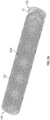
- FIG. 1A illustrates one embodiment of a medical device, comprising an exploded view of a catheter 1.
- the catheter 1 comprises an elongate, flexible portion 10 to be extendable from a controller (not shown) and a bendable portion 11 disposed at the distal end 100 of the elongate, flexible portion 10.
- FIG.1B is a cross-sectional view of the elongate, flexible portion 10 of the medical device in FIG. 1A .
- the elongate and flexible portion 10 further comprises a tubular inner liner 101, a support member 102, and an outer jacket 103.
- the bendable portion 11 includes an ionic electroactive polymer actuator 110 comprising a polymer electrolyte layer member 111 disposed adjacent to the inner liner 101 of the elongate, flexible portion 10 and centrally to a plurality of energizable electrodes 112.
- Each of the plurality of electrodes 112 that surround the exterior surface 113 of the polymer electrolyte layer 111 is connected to a distal end 120 ( Figs 4A, 4B ) of one of a plurality of electrically-conductive wires 12 through which an electrical signal or current may be supplied to the connected electrode 112.
- the inner liner 101 and the polymer electrolyte layer 111 further form an interior bore 104, 114 respectively, to guide an inserted guidewire (not shown) to a predetermined position within a lumen of the body.
- the polymer electrolyte layer 111 is secured adjacent to the distal end 100 of the inner liner 101 with the bore 114 of the polymer electrolyte layer aligned with the bore 104 of the inner liner 101.
- the inserted guidewire may be thus fed from the proximal end 105 of the elongate, flexible portion 10 through the bores 104, 114 to the distal end 115 of the bendable portion 11.
- the inner liner 101 is sufficiently slender to be inserted into a lumen (not shown) of a body (not shown), i.e., it has a sufficiently small cross section to allow this use. Also, the inner liner 101 is sufficiently flexible and substantially axially incompressible so that it can be advanced through a lumen having a winding pathway by pushing or driving the elongate, flexible portion 10 forward after the distal end 100 is introduced into the lumen of the body (not shown). In some exemplary examples, the inner liner 101 may be a lubricious liner which additionally is configured to provide strengthening and stiffening to the proximal portion of the catheter 1.
- the liner 101 can not only prevent the support member 102 thereon from being exposed on the inner surface of the catheter 1 and thus to the bore 104, but also can improve the lubricity of the catheter inner lumen surfaces (i.e. the wall surfaces of the bores 104, 114) to aid guidewire placement.
- the inner liner 101 may be formed with a low friction polymer which comprises fluorocarbon (such as polytetrafluoroethylene (PTFE)), high density polyethylene, other low-friction polymers, or combinations thereof, but is not limited to this.
- PTFE polytetrafluoroethylene
- the low friction polymer, such as PTFE may be combined with another more rigid polymer, such as polyimide to increase the strength of the inner liner 101.
- FIG. 2A is an isometric view of Fig. 1A illustrating the overall support member and the electrically-conductive wires.
- FIG. 2B is an enlarged view of a portion of the support member and the electrically-conductive wires in FIG. 1A .
- the support member 102 Surrounding the liner 101 are the support member 102, and a plurality of electrically-conductive wires 12, that are integrally braided together to provide a fairly secured-incorporated braided structure, thereby reducing damage to the vulnerable electrically-conductive wires 12 during assembly and use of the catheter 1.
- the support member 102 can provide enhanced structural rigidity and resistance to axial compression and enhanced resistance to torsional deformation of the elongate, flexible portion 10 for improved control and steerability of the catheter 1.
- the support member 102 may comprise, for example, but is not limited to a reinforcing mesh, a wire-braided matrix or a coil formed from one or more reinforcement materials 102a and the conductive wires 12 wound in a braided or other helical configuration around the inner liner 101.
- reinforcement materials 102a may include, but are not limited to, one or more round or flat (e.g., rectangular, elliptical, circular, ribbon, flat oval or other shape in section) wires, filaments, strands or the like formed from metal (e.g. stainless steel, Nitinol or tungsten), plastic (e.g. polyether ether ketone (PEEK), nylon), glass, woven or twisted fibers (e.g.
- the support member 102 may have reinforcement materials 102a formed at a fixed winding pitch.
- the support member 102 may be formed in three or more sections of differing pitches.
- the support member 102 may be provided with reinforcement materials 102a having a lower pitch(closer spacing) at the proximal end 105 to provide increased strength and a higher pitch (greater spacing) at the distal end 100 to provide increased kink resistance and flexibility.
- the outer jacket 103 is shown on the left side of FIG. 1A but is removed from the right side of FIG. 1A to reveal the liner 101, and the support member 102 braided with electrically-conductive wires 12 therein.
- the outer jacket 103 can include a low-friction polymer to reduce the forces required to advance the catheter through vasculature.
- the outer jacket 103 may comprise one or more materials including, but not limited to, nylon, polyurethane and/or a thermoplastic elastomer such as, for example, PEBAX ® , a polyether block amide material available from Arkema France Corporation of Colombes, France.
- the outer jacket 103 can be applied to the support member 102 via an extrusion, molding or shrink tubing assembly process. Further, a hydrophilic coating (not shown) can be applied on the outer surface of the outer jacket 103 to provide lubricious delivery and to aid in steerability of the catheter 1.
- the hydrophilic coating can be thin and constitute only a minor part of the wall thickness of the elongate, flexible portion 10.
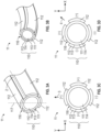
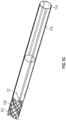
- FIG. 3A is a perspective view of the bendable portion 11 of the embodiment of the catheter of FIG. 1A , illustrating the bendable portion 11 in the straight mode.
- the bendable portion 11 includes an ionic electroactive polymer actuator 110 comprising a tubular polymer electrolyte layer 111 disposed adjacent to the distal end 100 of elongate, flexible portion 10 and centrally to an angularly-distributed plurality of energizable electrodes 112.
- Each of the plurality of electrodes 112 that together surround the exterior surface 113 of the polymer electrolyte layer 111 is connected to a distal end 120 of an electrically-conductive wire 12 through which an electrical signal or current may be supplied to the connected electrode 112.
- the polymer electrolyte layer 111 includes a bore 114 through which other elongate structures (e.g. a guidewire) may be inserted to position, control and/or actuate an end effector or surgical tool or instrument disposed at the distal end of the elongate structure.
- the bore 114 of the polymer electrolyte layer 111 is, in a relaxed or de-energized condition, centered about an axis 2.
- the angularly distributed electrodes 112 are equi-angularly distributed about the exterior surface 113 of the polymer electrolyte layer 111.
- the ionic electroactive polymer actuator 110 may, in the embodiment of FIG. 3A , comprise four angularly-distributed electrodes 112 that are separated, at their centerlines, each one from the others, by about 90 degrees (1.571 radians).
- each of the plurality of electrodes 112 occupies a circumferential span along the surface of the polymer electrolyte layer, and that the "angular separation" may therefore be stated in terms of the centerlines 117 of the electrodes instead of in terms of the adjacent edges of the electrodes, which will be much closer to the adjacent edge of the adjacent electrode.
- the electrodes are spaced in a manner to provide a substantial gap as insulation channels 116 intermediate adjacent electrodes.
- the ionic electroactive polymer actuator 110 of FIG. 3A is an ionic polymer-metal composite (IPMC) actuator.
- the ionic electroactive polymer actuator 110 includes a polymer electrolyte layer 111 made of PVDF-HFP that is impregnated with EMITF (as electrolyte).
- EMITF as electrolyte
- other embodiments of the ionic electroactive polymer actuator 110 of the catheter 1 may include a polymer electrolyte layer 111 that includes at least one of a perfluorinated ionomer such as Aciplex TM (available from Asahi Kasei Chemical Corp. of Tokyo, Japan), Flemion ® (available from AGC Chemical Americas, Inc.
- Aciplex TM available from Asahi Kasei Chemical Corp. of Tokyo, Japan
- Flemion ® available from AGC Chemical Americas, Inc.
- the electrodes 112 may include one of platinum, gold, a carbon-based material, or a combination (e.g. a composite) thereof.
- the carbon-material may include, for example, but is not limited to, carbide-derived carbon (CDC), carbon nanotube (CNT), graphene, a composite of carbide-derived carbon and the polymer electrolyte layer 111, and a composite of carbon nanotube and the polymer electrolyte layer 111.
- the electrodes 112 are double-layered, and include: a composite layer 112a of carbon (CDC and/or CNT) and PVDF-HFP/EMITF and a gold layer 112b thereover.
- the electrodes 112 can be integrated on the exterior surface 113 of the polymer electrolyte layer 111 using any suitable techniques.
- metal electrodes 112 can be deposited (e.g. platinum or gold electrodes) thereon using an electrochemical process.
- the double-layered electrodes 112 can be prepared and integrated on the exterior surface 113 by the following steps: spraying the composite layer 112a on the exterior surface 113, spray coating a gold layer 112b on the composite layer 112a, followed by integrating the layers 112a, 112b using a reflow process.
- the detail of the reflow process is discussed in PCT Application No. PCT/US17/16513 , which is fully incorporated herein by reference in its entirety.
- the bendable portion 11 can be selectively and controllably deformed to a bent mode by selective energization of one or more of the plurality of electrodes 112, as will be explained in further detail below.
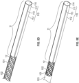
- FIG. 3B is an isometric view of the portion of the bendable portion 11 of FIG. 3A in the deformed or bending mode.
- Each of the plurality of electrodes 112 is connected to a distal end 120 of the electrically-conductive wire 12 through which an electrical signal may be applied to the electrodes 112 to which the wire 12 is connected, thereby causing metal cations within the polymer electrolyte layer 111 to move in a direction determined by the applied electrical signal.
- This cation migration produced by the applied electrical signal causes the polymer electrolyte layer 111 to swell in the portion of the polymer electrolyte layer 111 disposed proximal to the anode and to bend or warp in the direction of the remaining unswelled portion.
- the magnitude and the direction of bending deformation of the polymer electrolyte layer 111 of the ionic electroactive polymer actuator 110 can be controlled by strategically selecting the electrodes 112 to energize and by adjusting the electrical signal applied through the electrically-conductive wire 12 to those electrodes 112.
- the magnitude of the observed deflection can be used to determine the magnitude and direction of an external force applied to the bendable portion 11 or, alternately, in the event that the application of a known current to the electrodes 112 fails to produce an anticipated deformation of the bendable portion 11, the difference between the anticipated deformation and the actual deformation (if any) can be used as an indicator of the magnitude of an external force applied to the bendable portion 11 of the catheter 1.
- FIG. 3C is a cross-sectional view of the bendable portion 11 of FIGS. 3A and 3B illustrating one embodiment that a first selected set of four electrical signals is applied to four circumferentially distributed electrodes 112 disposed about the exterior surface 113 of the polymer electrolyte layer 111 to provide two degrees of freedom (e.g. bending along X-axis direction and/or Y-axis direction).
- FIG. 3C illustrates the electrical signals that may be applied to the plurality of angularly distributed electrodes 112 to impart bending of the bendable portion 11 in the direction of the arrow 3. It will be understood that the application of a positive charge (potential) on the electrodes 112 on the left and right sides of the bendable portion 11 of FIG.
- FIG. 3D is the cross-sectional view of the bendable portion 11 of FIG. 3A and 3B revealing another embodiment that a second selected set of four electrical signals applied to the circumferentially distributed electrodes 112 disposed about the polymer electrolyte layer 111.
- FIG. 3D illustrates the application of a positive charge (potential) to the electrode 112 at the top of the bendable portion 11 of FIG. 3D and also to the electrode 112 at the right side of the bendable portion 11 of FIG. 3D
- FIG. 3D further illustrates the application of a negative charge (potential) to the electrode 112 at the bottom of FIG. 3D and also to the electrode 112 at the left side of FIG. 3D .
- the deformation of the polymer electrolyte layer 111 results from the application of these electrical charges (potentials) is in the direction of the arrow 4.
- the bendable portion 11 of the catheter 1 can be bent in multiple directions and with varying degrees of deformation or deflection by strategic control of the sign (+, -) and magnitude of the electrical charges imparted to each of the individual electrodes 112.
- FIG. 3A to 3D illustrates a bendable portion 11 including four electrodes 112
- the bendable portion 11 of the catheter 1 may include fewer than four or more than four electrodes 112, and such other embodiments will have differing deflection and deformation directional capacities and thus provide more or less degree(s) of freedom.
- the electrically-conductive wires 12 can be interconnected with the electrodes 112 in various configurations using any suitable connecting technique. For example, conducting paste or laser welding can be employed to physically and electrically connect the electrically-conductive wires 12 and the electrodes 112.
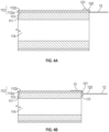
- FIG. 4A shows a longitudinal cross section of the ionic electroactive polymer actuator 110 of FIG. 1A , illustrating one embodiment of physical and electrical connection of the electrically-conductive wires 12 with the electrodes 112.
- the distal ends 120 of the electrically-conductive wires 12 extend along a portion of the surface of the gold layer 112b of each of the electrodes 112 at the proximal end 117 of the ionic electroactive polymer actuator 110 where they terminate in a connection with the electrode 112 using, for example, a small quantity of conductive paste 121.
- FIGs.4B to 4D illustrate other embodiments of physical and electrical connection of the electrically-conductive wires 12 and the electrodes 112.
- a conductive shunt hereafter a conductive bridge 13 is formed at the proximal end 117 of the ionic electroactive polymer actuator 110 and extends therefrom along the polymer electrolyte layer 111 to a connection location to the electrodes 112 and facilitates transmission of electrical potential therebetween.
- the conductive bridge 13 may be plated on the surface of the gold layer 112b and extend to cover a portion (see. FIG. 4B ) or all (see FIGS.
- the electrically-conductive wire 12 and the support member 102 are first located over the exterior surface 101 of the liner 101 from the proximal end 103 (see, e.g. FIG.
- the conductive bridge 13 can be prepared by applying any conductive foil or tape made of metallic materials (e.g. gold, silver or copper) or non-metallic materials comprising conductive polymers onto the surface of the electrodes 112 and the polymer electrolyte layer 111 using any suitable techniques (e.g. using adhesives, coating, plating, etching or depositing, but not limited to this method of application or to these materials).
- metallic materials e.g. gold, silver or copper
- non-metallic materials comprising conductive polymers
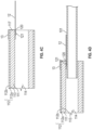
- FIGs 5A to 5E illustrate the integration of the elongate, flexible portion and the bendable portion of a catheter in FIG. 1 A according to one embodiment.
- FIG. 5A is a schematic view of the separate liner and the ionic electroactive polymer actuator.
- the ionic electroactive polymer actuator 110 can be prepared by depositing electrodes 112 on exterior surface 113 of a polymer electrolyte layer 112 made of a commercial Nafion ® tube or a PVDF tube.
- the polymer electrolyte layer 112 in a tubular shape can be prepared using a reflow process. The detail of the reflow process is discussed in PCT Application No. PCT/US17/16513 , which is fully incorporated herein by reference in its entirety.
- the electrodes 112 can be deposited using any suitable methods. For example, but not by way of limitation, electrodes 112 made of metal can be deposited (e.g. platinum or gold electrodes) thereon using an electrochemical process. Electrodes 112 made of carbon-based materials can be deposited using the reflow process discussed in PCT Application No. PCT/US17/16513 , which is fully incorporated herein by reference in its entirety. In other embodiments, the double-layered electrodes 112 (see, e.g. FIG.
- the inner liner 101 e.g. a PTFE liner
- the inner liner 101 may have a smaller outer diameter than the bore 114 of the polymer electrolyte layer 112 do, so that the inner liner 101 can be fitted into the bore 114 such that the inner liner 101 extends inwardly of the bore 114 by about 5 to 10 mm.
- a parylene encapsulation coating with the thickness of 5 to 10 ⁇ m may be coated over the liner 101 -bore 114 connection to reinforce the connection thereof.
- FIG. 5C and 5D illustrate schematic views of the interconnection of the electrically-conductive wires 12 and the electrodes 112.
- Any braiding equipment machine and technologies known in the art can be used to braid the electrically-conductive wires 12 and the support member 102 integrally.
- the braiding process can be performed using a braiding machine that offers vertical continuous reel-to-reel braiding, horizontal reel-to-reel braiding or mandrel braiding.
- the support member 102 with the electrically-conductive wires 12 braided therein is slid over the liner 101 as shown in FIG. 5D and attached thereto by an adhesive (e.g., a thermoplastic plastic or thermoset plastic), or by welding, or any combination thereof.
- an adhesive e.g., a thermoplastic plastic or thermoset plastic
- the distal ends of the electrically-conductive wires 12 extend from at least the distal end thereof.
- the distal ends 120 of the electrically-conductive wires 12 extending from the support member 102 can then be coupled to the ionic electroactive polymer actuator 110 directly (e.g. attached to a portion of the surface of the gold layer 112b of FIG. 4A ) or indirectly (e.g. through attachment to the conductive bridge 13 shown in FIG. 4B to 4D .)
- a mandrel (not shown), for example, a stainless steel mandrel rod having an outside diameter of 0.025" (0.635 mm) is fitted into the bores 104 and 114 so that the mandrel can support the inner liner 101 and the ionic electroactive polymer actuator 110 for the following assembling using the reflow process.
- a heat shrink tube (e.g.
- a fluorinated ethylene-propylene (FEP) tube may be positioned over the outer jacket 103 and the ionic electroactive polymer actuator 110 and heat may be applied to cause the heat shrink tube to wrap tightly around the outer jacket 103 and at least the proximal end of the ionic electroactive polymer actuator 110 to firmly secure the outer jacket 103 and the ionic electroactive polymer actuator 110 to one another by squeezing them together.
- the heat shrink tube and the mandrel is then be removed from the obtained catheter 1 using any suitable technique.
- the heat shrink tube can be skived.
Landscapes
- Health & Medical Sciences (AREA)
- Life Sciences & Earth Sciences (AREA)
- Veterinary Medicine (AREA)
- Animal Behavior & Ethology (AREA)
- General Health & Medical Sciences (AREA)
- Public Health (AREA)
- Engineering & Computer Science (AREA)
- Biophysics (AREA)
- Biomedical Technology (AREA)
- Heart & Thoracic Surgery (AREA)
- Pulmonology (AREA)
- Anesthesiology (AREA)
- Hematology (AREA)
- Epidemiology (AREA)
- Surgery (AREA)
- Chemical & Material Sciences (AREA)
- Molecular Biology (AREA)
- Medical Informatics (AREA)
- Optics & Photonics (AREA)
- Pathology (AREA)
- Radiology & Medical Imaging (AREA)
- Physics & Mathematics (AREA)
- Nuclear Medicine, Radiotherapy & Molecular Imaging (AREA)
- Inorganic Chemistry (AREA)
- Chemical Kinetics & Catalysis (AREA)
- Manufacturing & Machinery (AREA)
- Media Introduction/Drainage Providing Device (AREA)
- Electrotherapy Devices (AREA)
- Surgical Instruments (AREA)
- Infusion, Injection, And Reservoir Apparatuses (AREA)
- Micromachines (AREA)
Applications Claiming Priority (3)
| Application Number | Priority Date | Filing Date | Title |
|---|---|---|---|
| US201762539338P | 2017-07-31 | 2017-07-31 | |
| EP18841377.7A EP3548130B1 (de) | 2017-07-31 | 2018-07-27 | Lenkbare medizinische vorrichtung mit geflochtener struktur und herstellungsverfahren dafür |
| PCT/US2018/044057 WO2019027825A1 (en) | 2017-07-31 | 2018-07-27 | BRAZED STRUCTURE ORIENTABLE MEDICAL DEVICE AND METHOD FOR PREPARING THE SAME |
Related Parent Applications (1)
| Application Number | Title | Priority Date | Filing Date |
|---|---|---|---|
| EP18841377.7A Division EP3548130B1 (de) | 2017-07-31 | 2018-07-27 | Lenkbare medizinische vorrichtung mit geflochtener struktur und herstellungsverfahren dafür |
Publications (2)
| Publication Number | Publication Date |
|---|---|
| EP4424352A2 true EP4424352A2 (de) | 2024-09-04 |
| EP4424352A3 EP4424352A3 (de) | 2024-12-11 |
Family
ID=65234016
Family Applications (5)
| Application Number | Title | Priority Date | Filing Date |
|---|---|---|---|
| EP18841377.7A Active EP3548130B1 (de) | 2017-07-31 | 2018-07-27 | Lenkbare medizinische vorrichtung mit geflochtener struktur und herstellungsverfahren dafür |
| EP24181489.6A Pending EP4424352A3 (de) | 2017-07-31 | 2018-07-27 | Lenkbare medizinische vorrichtung mit geflochtener struktur und herstellungsverfahren dafür |
| EP24202235.8A Pending EP4461200A3 (de) | 2017-07-31 | 2018-07-27 | Steuerbare medizinische vorrichtung und herstellungsverfahren dafür |
| EP24202301.8A Pending EP4461201A3 (de) | 2017-07-31 | 2018-07-27 | Steuerbare medizinische vorrichtung und herstellungsverfahren dafür |
| EP18842340.4A Active EP3548131B1 (de) | 2017-07-31 | 2018-07-27 | Lenkbare medizinische vorrichtung und herstellungsverfahren dafür |
Family Applications Before (1)
| Application Number | Title | Priority Date | Filing Date |
|---|---|---|---|
| EP18841377.7A Active EP3548130B1 (de) | 2017-07-31 | 2018-07-27 | Lenkbare medizinische vorrichtung mit geflochtener struktur und herstellungsverfahren dafür |
Family Applications After (3)
| Application Number | Title | Priority Date | Filing Date |
|---|---|---|---|
| EP24202235.8A Pending EP4461200A3 (de) | 2017-07-31 | 2018-07-27 | Steuerbare medizinische vorrichtung und herstellungsverfahren dafür |
| EP24202301.8A Pending EP4461201A3 (de) | 2017-07-31 | 2018-07-27 | Steuerbare medizinische vorrichtung und herstellungsverfahren dafür |
| EP18842340.4A Active EP3548131B1 (de) | 2017-07-31 | 2018-07-27 | Lenkbare medizinische vorrichtung und herstellungsverfahren dafür |
Country Status (11)
| Country | Link |
|---|---|
| US (4) | US10835716B2 (de) |
| EP (5) | EP3548130B1 (de) |
| JP (2) | JP6798020B2 (de) |
| KR (2) | KR102118837B1 (de) |
| CN (2) | CN109843368B (de) |
| AU (2) | AU2018311844B9 (de) |
| BR (1) | BR112019007377B1 (de) |
| CA (2) | CA3039269C (de) |
| MX (2) | MX2020001267A (de) |
| TW (2) | TWI679036B (de) |
| WO (2) | WO2019027826A2 (de) |
Families Citing this family (30)
| Publication number | Priority date | Publication date | Assignee | Title |
|---|---|---|---|---|
| US9986893B2 (en) | 2009-12-15 | 2018-06-05 | Cornell University | Method and apparatus for manipulating the side wall of a body lumen or body cavity so as to provide increased visualization of the same and/or increased access to the same, and/or for stabilizing instruments relative to the same |
| US12121209B2 (en) | 2014-02-11 | 2024-10-22 | Cornell University | Method and apparatus for providing increased visualization and manipulation of a body side wall |
| US11986150B2 (en) | 2009-12-15 | 2024-05-21 | Lumendi Ltd. | Method and apparatus for manipulating the side wall of a body lumen or body cavity so as to provide increased visualization of the same and/or increased access to the same, and/or for stabilizing instruments relative to the same |
| US11877722B2 (en) | 2009-12-15 | 2024-01-23 | Cornell University | Method and apparatus for manipulating the side wall of a body lumen or body cavity |
| CA3063103C (en) | 2017-12-29 | 2020-12-22 | Xcath, Inc. | Steerable surgical robotic system |
| CN110789129A (zh) * | 2019-06-28 | 2020-02-14 | 东莞科威医疗器械有限公司 | 一种增强型医用插管及其制作方法 |
| CN110575603A (zh) * | 2019-10-14 | 2019-12-17 | 苏州法兰克曼医疗器械有限公司 | 一种具有可视功能的导丝输送装置 |
| EP4578490A3 (de) * | 2019-12-16 | 2025-07-30 | Galvani Bioelectronics Limited | Intravaskulärer neuromodulator mit stentelektrode |
| US20220392065A1 (en) | 2020-01-07 | 2022-12-08 | Cleerly, Inc. | Systems, methods, and devices for medical image analysis, diagnosis, risk stratification, decision making and/or disease tracking |
| US11969280B2 (en) | 2020-01-07 | 2024-04-30 | Cleerly, Inc. | Systems, methods, and devices for medical image analysis, diagnosis, risk stratification, decision making and/or disease tracking |
| CA3162872A1 (en) | 2020-01-07 | 2021-07-15 | James K. MIN | Systems, methods, and devices for medical image analysis, diagnosis, risk stratification, decision making and/or disease tracking |
| CN111729106B (zh) * | 2020-06-30 | 2021-08-13 | 北京航空航天大学 | 一种柔性低温等离子体灭菌装置 |
| CN112406252B (zh) * | 2020-10-12 | 2023-01-17 | 浙江理工大学 | 基于c-cnc纤维素的高性能电驱动ipmc柔性驱动器的制备方法 |
| CN112409627A (zh) * | 2020-10-12 | 2021-02-26 | 浙江理工大学 | 一种新型混合纤维素ipmc材料的制备方法 |
| US20220125454A1 (en) | 2020-10-23 | 2022-04-28 | Vicora, Inc. | Actuated thrombectomy device |
| US12022998B2 (en) * | 2020-11-16 | 2024-07-02 | Lumendi Ltd. | Methods and apparatus for inverting a hollow sleeve and thereafter reverting an inverted hollow sleeve |
| TWI759076B (zh) * | 2021-01-15 | 2022-03-21 | 陳映臻 | 治療內腔室傷口之藥劑推進裝置及其藥劑推進管 |
| WO2023060099A1 (en) | 2021-10-05 | 2023-04-13 | Corindus, Inc. | Robotic actuation of elongated medical devices |
| CN118925017A (zh) * | 2021-10-09 | 2024-11-12 | 上海卓矿鑫生物科技有限公司 | 防舌后坠鼻导管 |
| US20250143657A1 (en) | 2022-03-10 | 2025-05-08 | Cleerly, Inc. | Systems, devices, and methods for non-invasive image-based plaque analysis and risk determination |
| US12406365B2 (en) | 2022-03-10 | 2025-09-02 | Cleerly, Inc. | Systems, devices, and methods for non-invasive image-based plaque analysis and risk determination |
| US20250217981A1 (en) | 2022-03-10 | 2025-07-03 | Cleerly, Inc. | Systems, methods, and devices for image-based plaque analysis and risk determination |
| US12440180B2 (en) | 2022-03-10 | 2025-10-14 | Cleerly, Inc. | Systems, devices, and methods for non-invasive image-based plaque analysis and risk determination |
| US20240041480A1 (en) | 2022-08-02 | 2024-02-08 | Imperative Care, Inc. | Multi catheter system with integrated fluidics management |
| CN115430020A (zh) * | 2022-11-08 | 2022-12-06 | 山东百多安医疗器械股份有限公司 | 一种带柔性电极的导尿管 |
| US12442115B2 (en) * | 2022-12-13 | 2025-10-14 | Kuraray Co., Ltd. | High surface area braids |
| TWI893582B (zh) * | 2023-02-03 | 2025-08-11 | 香港商巧捷力醫療機器人有限公司 | 內視鏡手術用之可操縱臂的管狀本體及其製造方法 |
| WO2024238831A2 (en) | 2023-05-17 | 2024-11-21 | Imperative Care, Inc. | Fluidics control system for multi catheter stack |
| CN116617545B (zh) * | 2023-06-09 | 2024-03-22 | 株洲茂物医疗科技有限公司 | 导丝的制作方法和导丝 |
| WO2025076132A1 (en) * | 2023-10-02 | 2025-04-10 | Vicora, Inc. | Medical devices, systems and methods for delivering energy |
Citations (3)
| Publication number | Priority date | Publication date | Assignee | Title |
|---|---|---|---|---|
| US6679836B2 (en) | 2002-06-21 | 2004-01-20 | Scimed Life Systems, Inc. | Universal programmable guide catheter |
| US20070250036A1 (en) | 2006-04-25 | 2007-10-25 | Boston Scientific Scimed, Inc. | Variable stiffness catheter assembly |
| US8414632B2 (en) | 2006-03-06 | 2013-04-09 | Boston Scientific Scimed, Inc. | Adjustable catheter tip |
Family Cites Families (29)
| Publication number | Priority date | Publication date | Assignee | Title |
|---|---|---|---|---|
| US4808157A (en) * | 1987-07-13 | 1989-02-28 | Neuro Delivery Technology, Inc. | Multi-lumen epidural-spinal needle |
| US5415633A (en) * | 1993-07-28 | 1995-05-16 | Active Control Experts, Inc. | Remotely steered catheterization device |
| JPH0810336A (ja) | 1994-06-30 | 1996-01-16 | Agency Of Ind Science & Technol | 医療用チューブ |
| US6616996B1 (en) * | 1994-10-28 | 2003-09-09 | Medsource Trenton, Inc. | Variable stiffness microtubing and method of manufacture |
| US5755704A (en) * | 1996-10-29 | 1998-05-26 | Medtronic, Inc. | Thinwall guide catheter |
| US7494474B2 (en) * | 1997-06-04 | 2009-02-24 | Advanced Cardiovascular Systems, Inc. | Polymer coated guidewire |
| US5891114A (en) * | 1997-09-30 | 1999-04-06 | Target Therapeutics, Inc. | Soft-tip high performance braided catheter |
| US6117296A (en) | 1998-07-21 | 2000-09-12 | Thomson; Timothy | Electrically controlled contractile polymer composite |
| US6464684B1 (en) | 1998-09-09 | 2002-10-15 | Scimed Life Systems, Inc. | Catheter having regions of differing braid densities and methods of manufacture therefor |
| WO2005018428A2 (en) * | 2000-04-03 | 2005-03-03 | Neoguide Systems, Inc. | Activated polymer articulated instruments and methods of insertion |
| US8398693B2 (en) * | 2004-01-23 | 2013-03-19 | Boston Scientific Scimed, Inc. | Electrically actuated medical devices |
| JP4732798B2 (ja) * | 2005-05-19 | 2011-07-27 | 株式会社日立製作所 | アクチュエーターおよびアクチュエーターモジュール |
| US7553387B2 (en) * | 2005-10-04 | 2009-06-30 | Ilh, Llc | Catheters with lubricious linings and methods for making and using them |
| WO2007057132A1 (en) * | 2005-11-17 | 2007-05-24 | Micromuscle Ab | Medical devices and methods for their fabrication and use |
| JP2007209554A (ja) * | 2006-02-09 | 2007-08-23 | Terumo Corp | カテーテル |
| US20070249909A1 (en) | 2006-04-25 | 2007-10-25 | Volk Angela K | Catheter configurations |
| US7909844B2 (en) * | 2006-07-31 | 2011-03-22 | Boston Scientific Scimed, Inc. | Catheters having actuatable lumen assemblies |
| US9370640B2 (en) * | 2007-09-12 | 2016-06-21 | Novasentis, Inc. | Steerable medical guide wire device |
| US20100069882A1 (en) * | 2008-09-18 | 2010-03-18 | Boston Scientific Scimed, Inc. | Medical device with preferential bending |
| US9717553B2 (en) * | 2010-12-29 | 2017-08-01 | Biosence Webster (Israel) Ltd. | Braid with integrated signal conductors |
| US20130116705A1 (en) * | 2011-05-03 | 2013-05-09 | Amr Salahieh | Steerable Delivery Sheaths |
| EP2747634A4 (de) | 2011-08-22 | 2015-05-06 | Lake Region Mfg Inc D B A Lake Region Medical | Mehradriger führungsdraht mit niedrigem profil |
| US9147825B2 (en) | 2012-03-07 | 2015-09-29 | Board of Regents of the Nevada System of Higher Education on behalf of the University of Nevado, Reno | Methods of fabricating multi-degree of freedom shaped electroactive polymer actuators/sensors for catheters |
| CN103860258A (zh) * | 2012-12-12 | 2014-06-18 | 北京中孵友信医药科技股份有限公司 | 自适应式环向定位腔内导管 |
| WO2014100402A1 (en) * | 2012-12-21 | 2014-06-26 | Howard Alpert | System and method for guidewire control |
| US9364635B2 (en) * | 2013-09-20 | 2016-06-14 | Covidien Lp | Computer controlled steerable tip guide catheter |
| WO2015061674A1 (en) * | 2013-10-25 | 2015-04-30 | Intuitive Surgical Operations, Inc. | Flexible instrument with grooved steerable tube |
| FR3019993B1 (fr) * | 2014-04-16 | 2019-07-19 | Institut National Des Sciences Appliquees De Lyon | Fil de guidage a flexibilite variable controlee |
| CN112138265B (zh) * | 2016-02-05 | 2022-10-28 | 得克萨斯系统大学董事会 | 制备采取管状形状的聚合物电解质层的方法 |
-
2018
- 2018-07-27 EP EP18841377.7A patent/EP3548130B1/de active Active
- 2018-07-27 BR BR112019007377-9A patent/BR112019007377B1/pt active IP Right Grant
- 2018-07-27 AU AU2018311844D patent/AU2018311844B9/en active Active
- 2018-07-27 JP JP2019520901A patent/JP6798020B2/ja active Active
- 2018-07-27 AU AU2018311843A patent/AU2018311843B2/en active Active
- 2018-07-27 US US16/478,435 patent/US10835716B2/en active Active
- 2018-07-27 MX MX2020001267A patent/MX2020001267A/es unknown
- 2018-07-27 EP EP24181489.6A patent/EP4424352A3/de active Pending
- 2018-07-27 CN CN201880003922.4A patent/CN109843368B/zh active Active
- 2018-07-27 KR KR1020197010799A patent/KR102118837B1/ko active Active
- 2018-07-27 TW TW107126073A patent/TWI679036B/zh active
- 2018-07-27 WO PCT/US2018/044059 patent/WO2019027826A2/en not_active Ceased
- 2018-07-27 US US16/478,425 patent/US11229775B2/en active Active
- 2018-07-27 CA CA3039269A patent/CA3039269C/en active Active
- 2018-07-27 EP EP24202235.8A patent/EP4461200A3/de active Pending
- 2018-07-27 KR KR1020197010800A patent/KR102086979B1/ko active Active
- 2018-07-27 EP EP24202301.8A patent/EP4461201A3/de active Pending
- 2018-07-27 EP EP18842340.4A patent/EP3548131B1/de active Active
- 2018-07-27 WO PCT/US2018/044057 patent/WO2019027825A1/en not_active Ceased
- 2018-07-27 CN CN201880003921.XA patent/CN110461400B/zh active Active
- 2018-07-27 JP JP2019520807A patent/JP6831455B2/ja active Active
- 2018-07-27 MX MX2019004430A patent/MX2019004430A/es unknown
- 2018-07-27 CA CA3039267A patent/CA3039267C/en active Active
- 2018-07-27 TW TW107126074A patent/TWI683678B/zh active
-
2021
- 2021-12-16 US US17/553,371 patent/US12171958B2/en active Active
-
2024
- 2024-12-23 US US18/999,592 patent/US20250128028A1/en active Pending
Patent Citations (4)
| Publication number | Priority date | Publication date | Assignee | Title |
|---|---|---|---|---|
| US6679836B2 (en) | 2002-06-21 | 2004-01-20 | Scimed Life Systems, Inc. | Universal programmable guide catheter |
| US8414632B2 (en) | 2006-03-06 | 2013-04-09 | Boston Scientific Scimed, Inc. | Adjustable catheter tip |
| US20070250036A1 (en) | 2006-04-25 | 2007-10-25 | Boston Scientific Scimed, Inc. | Variable stiffness catheter assembly |
| US7766896B2 (en) | 2006-04-25 | 2010-08-03 | Boston Scientific Scimed, Inc. | Variable stiffness catheter assembly |
Also Published As
Similar Documents
| Publication | Publication Date | Title |
|---|---|---|
| US12171958B2 (en) | Method for preparing a steerable medical device with braided structure | |
| JP2020513863A6 (ja) | 操向可能な医療機器及びその作製方法 | |
| HK40004551B (zh) | 具有编织结构的可转向医疗装置及其制备方法 | |
| HK40004551A (en) | Steerable medical device with braided structure and the preparing method thereof | |
| BR122022025740B1 (pt) | Método para a preparação de um dispositivo médico | |
| BR122022025739B1 (pt) | Dispositivo médico alongado e flexível | |
| BR112019007355B1 (pt) | Dispositivo médico flexível | |
| HK40011281A (en) | Steerable medical device and the preparing method thereof | |
| HK40011281B (en) | Steerable medical device and the preparing method thereof |
Legal Events
| Date | Code | Title | Description |
|---|---|---|---|
| PUAI | Public reference made under article 153(3) epc to a published international application that has entered the european phase |
Free format text: ORIGINAL CODE: 0009012 |
|
| STAA | Information on the status of an ep patent application or granted ep patent |
Free format text: STATUS: THE APPLICATION HAS BEEN PUBLISHED |
|
| AC | Divisional application: reference to earlier application |
Ref document number: 3548130 Country of ref document: EP Kind code of ref document: P |
|
| AK | Designated contracting states |
Kind code of ref document: A2 Designated state(s): AL AT BE BG CH CY CZ DE DK EE ES FI FR GB GR HR HU IE IS IT LI LT LU LV MC MK MT NL NO PL PT RO RS SE SI SK SM TR |
|
| RIN1 | Information on inventor provided before grant (corrected) |
Inventor name: SHIM, YOUNGHEE Inventor name: PALMRE, VILJAR Inventor name: KIM, DANIEL Inventor name: SHIN, DONG SUK |
|
| REG | Reference to a national code |
Ref country code: DE Ref legal event code: R079 Free format text: PREVIOUS MAIN CLASS: A61M0025090000 Ipc: A61M0025010000 |
|
| PUAL | Search report despatched |
Free format text: ORIGINAL CODE: 0009013 |
|
| AK | Designated contracting states |
Kind code of ref document: A3 Designated state(s): AL AT BE BG CH CY CZ DE DK EE ES FI FR GB GR HR HU IE IS IT LI LT LU LV MC MK MT NL NO PL PT RO RS SE SI SK SM TR |
|
| RIC1 | Information provided on ipc code assigned before grant |
Ipc: A61L 29/14 20060101ALI20241105BHEP Ipc: A61L 29/04 20060101ALI20241105BHEP Ipc: A61L 29/02 20060101ALI20241105BHEP Ipc: A61L 29/08 20060101ALI20241105BHEP Ipc: A61M 25/00 20060101ALI20241105BHEP Ipc: A61M 25/01 20060101AFI20241105BHEP |
|
| STAA | Information on the status of an ep patent application or granted ep patent |
Free format text: STATUS: REQUEST FOR EXAMINATION WAS MADE |
|
| 17P | Request for examination filed |
Effective date: 20250611 |