EP4424236A2 - Abbildungskammer für ein abbildungssystem - Google Patents
Abbildungskammer für ein abbildungssystem Download PDFInfo
- Publication number
- EP4424236A2 EP4424236A2 EP24154918.7A EP24154918A EP4424236A2 EP 4424236 A2 EP4424236 A2 EP 4424236A2 EP 24154918 A EP24154918 A EP 24154918A EP 4424236 A2 EP4424236 A2 EP 4424236A2
- Authority
- EP
- European Patent Office
- Prior art keywords
- imaging
- imaging chamber
- fluid sample
- flow
- chamber
- Prior art date
- Legal status (The legal status is an assumption and is not a legal conclusion. Google has not performed a legal analysis and makes no representation as to the accuracy of the status listed.)
- Pending
Links
Images




Classifications
-
- G—PHYSICS
- G06—COMPUTING OR CALCULATING; COUNTING
- G06T—IMAGE DATA PROCESSING OR GENERATION, IN GENERAL
- G06T7/00—Image analysis
- G06T7/90—Determination of colour characteristics
-
- A—HUMAN NECESSITIES
- A61—MEDICAL OR VETERINARY SCIENCE; HYGIENE
- A61B—DIAGNOSIS; SURGERY; IDENTIFICATION
- A61B5/00—Measuring for diagnostic purposes; Identification of persons
- A61B5/145—Measuring characteristics of blood in vivo, e.g. gas concentration or pH-value ; Measuring characteristics of body fluids or tissues, e.g. interstitial fluid or cerebral tissue
- A61B5/14507—Measuring characteristics of blood in vivo, e.g. gas concentration or pH-value ; Measuring characteristics of body fluids or tissues, e.g. interstitial fluid or cerebral tissue specially adapted for measuring characteristics of body fluids other than blood
-
- A—HUMAN NECESSITIES
- A61—MEDICAL OR VETERINARY SCIENCE; HYGIENE
- A61B—DIAGNOSIS; SURGERY; IDENTIFICATION
- A61B5/00—Measuring for diagnostic purposes; Identification of persons
- A61B5/145—Measuring characteristics of blood in vivo, e.g. gas concentration or pH-value ; Measuring characteristics of body fluids or tissues, e.g. interstitial fluid or cerebral tissue
- A61B5/14546—Measuring characteristics of blood in vivo, e.g. gas concentration or pH-value ; Measuring characteristics of body fluids or tissues, e.g. interstitial fluid or cerebral tissue for measuring analytes not otherwise provided for, e.g. ions, cytochromes
-
- A—HUMAN NECESSITIES
- A61—MEDICAL OR VETERINARY SCIENCE; HYGIENE
- A61B—DIAGNOSIS; SURGERY; IDENTIFICATION
- A61B5/00—Measuring for diagnostic purposes; Identification of persons
- A61B5/145—Measuring characteristics of blood in vivo, e.g. gas concentration or pH-value ; Measuring characteristics of body fluids or tissues, e.g. interstitial fluid or cerebral tissue
- A61B5/1455—Measuring characteristics of blood in vivo, e.g. gas concentration or pH-value ; Measuring characteristics of body fluids or tissues, e.g. interstitial fluid or cerebral tissue using optical sensors, e.g. spectral photometrical oximeters
-
- A—HUMAN NECESSITIES
- A61—MEDICAL OR VETERINARY SCIENCE; HYGIENE
- A61B—DIAGNOSIS; SURGERY; IDENTIFICATION
- A61B6/00—Apparatus or devices for radiation diagnosis; Apparatus or devices for radiation diagnosis combined with radiation therapy equipment
- A61B6/52—Devices using data or image processing specially adapted for radiation diagnosis
- A61B6/5211—Devices using data or image processing specially adapted for radiation diagnosis involving processing of medical diagnostic data
- A61B6/5217—Devices using data or image processing specially adapted for radiation diagnosis involving processing of medical diagnostic data extracting a diagnostic or physiological parameter from medical diagnostic data
-
- A—HUMAN NECESSITIES
- A61—MEDICAL OR VETERINARY SCIENCE; HYGIENE
- A61M—DEVICES FOR INTRODUCING MEDIA INTO, OR ONTO, THE BODY; DEVICES FOR TRANSDUCING BODY MEDIA OR FOR TAKING MEDIA FROM THE BODY; DEVICES FOR PRODUCING OR ENDING SLEEP OR STUPOR
- A61M1/00—Suction or pumping devices for medical purposes; Devices for carrying-off, for treatment of, or for carrying-over, body-liquids; Drainage systems
- A61M1/14—Dialysis systems; Artificial kidneys; Blood oxygenators ; Reciprocating systems for treatment of body fluids, e.g. single needle systems for hemofiltration or pheresis
- A61M1/28—Peritoneal dialysis ; Other peritoneal treatment, e.g. oxygenation
-
- A—HUMAN NECESSITIES
- A61—MEDICAL OR VETERINARY SCIENCE; HYGIENE
- A61M—DEVICES FOR INTRODUCING MEDIA INTO, OR ONTO, THE BODY; DEVICES FOR TRANSDUCING BODY MEDIA OR FOR TAKING MEDIA FROM THE BODY; DEVICES FOR PRODUCING OR ENDING SLEEP OR STUPOR
- A61M5/00—Devices for bringing media into the body in a subcutaneous, intra-vascular or intramuscular way; Accessories therefor, e.g. filling or cleaning devices, arm-rests
- A61M5/007—Devices for bringing media into the body in a subcutaneous, intra-vascular or intramuscular way; Accessories therefor, e.g. filling or cleaning devices, arm-rests for contrast media
-
- G—PHYSICS
- G01—MEASURING; TESTING
- G01N—INVESTIGATING OR ANALYSING MATERIALS BY DETERMINING THEIR CHEMICAL OR PHYSICAL PROPERTIES
- G01N15/00—Investigating characteristics of particles; Investigating permeability, pore-volume or surface-area of porous materials
- G01N15/10—Investigating individual particles
- G01N15/14—Optical investigation techniques, e.g. flow cytometry
- G01N15/1434—Optical arrangements
- G01N15/1436—Optical arrangements the optical arrangement forming an integrated apparatus with the sample container, e.g. a flow cell
-
- G—PHYSICS
- G01—MEASURING; TESTING
- G01N—INVESTIGATING OR ANALYSING MATERIALS BY DETERMINING THEIR CHEMICAL OR PHYSICAL PROPERTIES
- G01N15/00—Investigating characteristics of particles; Investigating permeability, pore-volume or surface-area of porous materials
- G01N15/10—Investigating individual particles
- G01N15/14—Optical investigation techniques, e.g. flow cytometry
- G01N15/1484—Optical investigation techniques, e.g. flow cytometry microstructural devices
-
- G—PHYSICS
- G06—COMPUTING OR CALCULATING; COUNTING
- G06T—IMAGE DATA PROCESSING OR GENERATION, IN GENERAL
- G06T7/00—Image analysis
- G06T7/0002—Inspection of images, e.g. flaw detection
- G06T7/0012—Biomedical image inspection
-
- A—HUMAN NECESSITIES
- A61—MEDICAL OR VETERINARY SCIENCE; HYGIENE
- A61B—DIAGNOSIS; SURGERY; IDENTIFICATION
- A61B10/00—Instruments for taking body samples for diagnostic purposes; Other methods or instruments for diagnosis, e.g. for vaccination diagnosis, sex determination or ovulation-period determination; Throat striking implements
- A61B10/0045—Devices for taking samples of body liquids
- A61B10/007—Devices for taking samples of body liquids for taking urine samples
-
- A—HUMAN NECESSITIES
- A61—MEDICAL OR VETERINARY SCIENCE; HYGIENE
- A61B—DIAGNOSIS; SURGERY; IDENTIFICATION
- A61B5/00—Measuring for diagnostic purposes; Identification of persons
- A61B5/68—Arrangements of detecting, measuring or recording means, e.g. sensors, in relation to patient
- A61B5/6846—Arrangements of detecting, measuring or recording means, e.g. sensors, in relation to patient specially adapted to be brought in contact with an internal body part, i.e. invasive
- A61B5/6847—Arrangements of detecting, measuring or recording means, e.g. sensors, in relation to patient specially adapted to be brought in contact with an internal body part, i.e. invasive mounted on an invasive device
- A61B5/6866—Extracorporeal blood circuits, e.g. dialysis circuits
-
- G—PHYSICS
- G01—MEASURING; TESTING
- G01N—INVESTIGATING OR ANALYSING MATERIALS BY DETERMINING THEIR CHEMICAL OR PHYSICAL PROPERTIES
- G01N15/00—Investigating characteristics of particles; Investigating permeability, pore-volume or surface-area of porous materials
- G01N15/01—Investigating characteristics of particles; Investigating permeability, pore-volume or surface-area of porous materials specially adapted for biological cells, e.g. blood cells
- G01N2015/016—White blood cells
-
- G—PHYSICS
- G01—MEASURING; TESTING
- G01N—INVESTIGATING OR ANALYSING MATERIALS BY DETERMINING THEIR CHEMICAL OR PHYSICAL PROPERTIES
- G01N15/00—Investigating characteristics of particles; Investigating permeability, pore-volume or surface-area of porous materials
- G01N15/10—Investigating individual particles
- G01N15/14—Optical investigation techniques, e.g. flow cytometry
- G01N2015/1486—Counting the particles
-
- G—PHYSICS
- G06—COMPUTING OR CALCULATING; COUNTING
- G06T—IMAGE DATA PROCESSING OR GENERATION, IN GENERAL
- G06T2207/00—Indexing scheme for image analysis or image enhancement
- G06T2207/30—Subject of image; Context of image processing
- G06T2207/30004—Biomedical image processing
- G06T2207/30101—Blood vessel; Artery; Vein; Vascular
- G06T2207/30104—Vascular flow; Blood flow; Perfusion
Definitions
- Example embodiments of the present disclosure relate generally to an imaging chamber for imaging a fluid sample. More specifically, example embodiments of the present disclosure relate to an imaging chamber that is configured to allow a fluid sample to mix with a contrast-enhancing agent, forming a fluid mixture. The fluid mixture within the imaging chamber can subsequently be imaged by an imaging system (e.g., a digital holography image device).
- an imaging system e.g., a digital holography image device
- Fluid samples from patients are often mixed with a contrast-enhancing agent to facilitate the differentiation of particles or cells within the fluid sample when the sample is imaged (e.g., imaged by a digital holography image device).
- the image data of the fluid mixture is often analyzed for identification and classification of white blood cells to determine whether a patient has an infection.
- contrast-enhancing agent can be time consuming and require certain expertise because it often involves iterative 'fixing', staining, and rinsing steps. This deficiency becomes even more problematic when the fluid sample is being handled and imaged by an individual that is unskilled in using contrast-enhancing agents.
- peritoneal dialysis is often performed outside of a clinic and at a patient's home. It may be beneficial to collect the image data of the PD effluent within a relatively short time frame from when the fluid flows out of the patient's body. For example, it may be more beneficial for the image data of the PD effluent to be generated at the patient's home instead of delivering the fluid sample to a lab or a clinic for analysis. Because patients, in general, can be unskilled at mixing the contrast-enhancing agent with the fluid sample, the iterative fixing, staining, and rinsing steps of conventional methods may not have desired results.
- embodiments of the present disclosure provided herein include methods and apparatuses to provide for an improved imaging chamber.
- an imaging chamber configured to receive a flow of a fluid sample.
- the imaging chamber can include a reservoir and an imaging window.
- the reservoir can include a contrast-enhancing agent and can be configured to receive the flow of the fluid sample.
- the imaging window can be in fluid communication with the reservoir and downstream from the reservoir.
- the imaging window is optically clear.
- the imaging chamber can be configured to be imaged by an imaging system that includes an illumination device and an imaging device.
- the imaging chamber includes a mixing device that is upstream from the imaging window.
- the imaging chamber includes a flow restriction device that is configured to be in an open position and in a closed position, wherein the flow restriction device is configured to allow a flow of the fluid sample and/or a flow of the contrast-enhancing agent to flow through and/or past the flow restriction device when the flow restriction device is in the open position, and wherein the flow restriction device is configured to prevent the flow of the fluid sample and/or the flow of the contrast-enhancing agent to flow through and/or past the flow restriction device when the flow restriction device is in the closed position.
- the imaging chamber includes an encapsulation.
- the contrast-enhancing agent can be encapsulated within the encapsulation of the imaging chamber.
- the imaging chamber can include a seal-breaking mechanism that is configured to break the encapsulation of the imaging chamber.
- the seal-breaking mechanism can be configured to puncture a tube that comprises the flow of the fluid sample.
- the fluid sample is a peritoneal dialysis (PD) effluent.
- PD peritoneal dialysis
- the imaging chamber includes a puncturing mechanism that is configured to pierce a drainage bag or tube.
- the imaging chamber can receive the flow of the fluid sample through the puncturing mechanism.
- an imaging system is configured to receive an imaging chamber.
- the imaging system can include an illumination device and an imaging device.
- the imaging system can be configured to receive the imaging chamber between the illumination device and the imaging device.
- the imaging chamber can include a reservoir comprising a contrast-enhancing agent, the reservoir configured to receive a flow of a fluid sample.
- the imaging chamber can include an imaging window in fluid communication with the reservoir and downstream from the reservoir.
- the imaging device can be configured to be aligned with the imaging window of the imaging chamber.
- the imaging system includes an agitation device that is configured to agitate or shake the imaging chamber.
- the imaging system is configured to receive the flow of the fluid sample and the imaging chamber is configured to be within the imaging system when it receives the flow of the fluid sample.
- a method for imaging a fluid mixture with an imaging system includes receiving a fluid sample that includes biological cells into an imaging chamber.
- the imaging chamber can include a contrast-enhancing agent.
- the method can include mixing the fluid sample with the contrast-enhancing agent to form the fluid mixture and imaging the fluid mixture that is within the imaging chamber with the imaging system.
- receiving the fluid sample includes receiving the fluid sample from a bag or tube.
- the method includes opening a flow restriction device of the imaging chamber.
- mixing the fluid sample with the contrast-enhancing agent includes mixing the fluid sample with the contrast-enhancing agent with a mixing device.
- the fluid sample comprises a PD effluent.
- the imaging system comprises a digital holography imaging device.
- mixing the fluid sample with the contrast-enhancing agent is performed by hand outside of the imaging system.
- mixing the fluid sample with the contrast-enhancing agent is performed inside the imaging system by an agitation device of the imaging system.
- exemplary means serving as an example, instance, or illustration. Any aspect or design described herein as "exemplary” is not necessarily to be construed as preferred or advantageous over other aspects or designs. Rather, use of the word exemplary is intended to present concepts in a concrete fashion.
- a particular feature may be disclosed with respect to only one of several implementations, such feature may be combined with one or more other features of the other implementations as may be desired and advantageous for any given or particular application.
- the terms “includes” and “including” and variants thereof are used in either the detailed description or the claims, these terms are intended to be inclusive in a manner similar to the term “comprising.”
- the term "or” is intended to mean an inclusive “or” rather than an exclusive “or”. That is, unless specified otherwise, or clear from context, "X employs A or B” is intended to mean any of the natural inclusive permutations. That is, if X employs A; X employs B; or X employs both A and B, then "X employs A or B” is satisfied under any of the foregoing instances.
- the articles “a” and “an” as used in this application and the appended claims should generally be construed to mean “one or more” unless specified otherwise or clear from context to be directed to a singular form.
- upstream and downstream refer to the relative direction with respect to fluid flow in a fluid pathway.
- upstream refers to the direction from which the fluid flows
- downstream refers to the direction to which the fluid flows.
- fluid communication means that a fluid is capable of making the connection between the areas specified.
- Coupled refers to both direct coupling, fixing, or attaching, as well as indirect coupling, fixing, or attaching through one or more intermediate components or features, unless otherwise specified herein.
- the term "positioned directly on” refers to a first component being positioned on a second component such that they make contact.
- the term “positioned directly between” refers to a first component being positioned between a second component and a third component such that the first component makes contact with both the second component and the third component.
- a first component that is "positioned between" a second component and a third component may or may not have contact with the second component and the third component.
- a first component that is "positioned between" a second component and a third component is positioned such that there may be other intervening components between the second component and the third component other than the first component.
- a patient 800 undergoing a peritoneal dialysis (PD) procedure is schematically depicted, according to an example embodiment.
- the PD procedure provides a mechanism to remove waste products from a patient's blood when the patient's kidneys cannot adequately function.
- a cleansing fluid such as, but not limited to, a dialysis solution such as water with sugar and other additives
- a treatment solution bag 101 flows from a treatment solution bag 101, through a tube or a pipe (such as, but not limited to, a catheter), and into the patient's body 800. More specifically, the cleansing fluid is injected into a part of a patient's abdomen.
- the cleansing fluid When the cleansing fluid is inside the patient's body 800, the cleansing fluid absorbs waste products from the patient's body 800.
- the lining of the abdomen also known as peritoneum
- peritoneum can act as a filter and remove waste products from the patient's blood.
- the fluid with the filtered waste products referred herein as peritoneal dialysis (PD) effluent
- PD peritoneal dialysis
- PD procedures may be faced with some drawbacks.
- One of the drawbacks is that patients who undergo PD may develop infections.
- early detection of infections after a patient undergoes PD can be beneficial for alerting patients, as well as care providers, so that early action can be taken to limit the severity and frequency of infections.
- Various embodiments of the present disclosures may enable such early detection of infections while a patient undergoes PD.
- an imaging system 400 ( FIG. 17 ) that provides a mechanism to sample PD effluent and capture image data associated with the PD effluent.
- a contrast-enhancing agent 521 is mixed with the fluid sample 108, such as the PD effluent, to form a fluid mixture 556.
- the fluid mixture 556 can then be imaged by the imaging system 400 and the images captured by the imaging system 400 can be analyzed to count, identify, and/or classify particles and/or cells in the fluid mixture 556.
- certain types or quantities of particles or cells such as white blood cells, may indicate that the patient may have, or may be developing, an infection.
- the fluid mixture 556 which is a mixture of the fluid sample 108 and the contrast-enhancing agent 521, may be easier to analyze than the fluid sample 108 without the contrast-enhancing agent 521.
- conventional methods of mixing the contrast-enhancing agent 521 with a fluid sample 108 can be manual, time consuming, and may require certain expertise to successfully stain the particles and cells within the fluid sample 108.
- new methods and apparatuses to prepare a fluid mixture 556 of a fluid sample 108 and a contrast-enhancing agent 521 would be welcomed in the art.
- PD effluent can flow out of the patient's body 800, through at least one tube 102 and to a drainage bag 105.
- An imaging chamber 500 can be positioned to receive a fluid sample 108, such as the PD effluent that flows out of the patient's body 800.
- the imaging chamber 500 can include a contrast-enhancing agent and can be configured to mix the fluid sample 108 with the contrast-enhancing agent 521 to form a fluid mixture 556 that can be imaged by an imaging system 400.
- the imaging chamber 500 is in fluid communication with at least one of the tubes 102.
- the imaging chamber 500 can be positioned on the tube 102 that is coupled to the drainage bag 105.
- the imaging chamber 500 can be housed within a collection device 103.
- the imaging chamber 500 can be positioned within the imaging system 400.
- the PD effluent can flow from the patient's body 800 and into the imaging chamber 500, which is positioned within the imaging system 400.
- the PD effluent can flow into a drainage bag 105.
- the PD effluent can be extracted from the drainage bag 105 and into the imaging chamber 500, which can be inserted into the imaging system 400 to capture image data associated with the PD effluent.
- FIGS. 2A-2C an imaging chamber 500 that is configured to receive PD effluent from a drainage bag 105 is depicted, according to an example embodiment. More specifically, FIG. 2A depicts a perspective view of the imaging chamber 500 clamped onto a drainage bag 105, FIG. 2B depicts a top view of the imaging chamber 500, and FIG. 2C depicts a side view of the imaging chamber 500. As depicted in FIG. 2A , the imaging chamber 500 can be configured to clamp onto a periphery of the drainage bag 105.
- the imaging chamber 500 can include one or more puncturing mechanisms 536, such as needles, to pierce the drainage bag 105 and subsequently fluidly connect the imaging chamber 500 to the drainage bag 105, and allow the PD effluent to flow from the drainage bag 105 and into the imaging chamber 500.
- the imaging chamber 500 receives the flow of the fluid sample 108 through the puncturing mechanisms 536, which can be hollow needles.
- the imaging chamber 500 can include an imaging window 510.
- the imaging window 510 can be the location that the imaging system 400 images the fluid mixture 556. As depicted in FIG. 2B , the imaging window can be positioned at an extremity of the imaging chamber 500 at a location where the thickness of the imaging chamber 500 is relatively thin.
- FIGS. 3A-3C an imaging chamber 500 that is configured to obtain the fluid sample 108, such as PD effluent, from a drainage bag 105 is depicted, according to an example embodiment. More specifically, FIG. 3A depicts a perspective view of the imaging chamber 500 attached to a drainage bag 105, FIG. 3B depicts a top view of the imaging chamber 500, and FIG. 3C depicts a side view of the imaging chamber 500. As depicted in FIG. 3A , the imaging chamber 500 can be configured to puncture a side of the drainage bag 105.
- the imaging chamber 500 can include one or more puncturing mechanisms 536, such as needles, to fluidly connect the imaging chamber 500 to the drainage bag 105 and allow the fluid sample 108 to flow from the drainage bag 105 and into the imaging chamber 500.
- the imaging chamber 500 is an assembly that includes a first portion 561 that is configured to adhere to the drainage bag 105 and a second portion 562, which includes the imaging chamber 500, that is removably coupled to the first portion 561.
- the first portion 561 and the second portion 562 can include threads and the second portion 562, which includes the imaging chamber 500, can be twisted and removed from the first portion 561 that is adhered to the drainage bag 105.
- each of the examples provided can be configured to receive a fluid sample 108, such as PD effluent, either from a tube, such as tube 102 that has a flow of the fluid sample 108, or from a drainage bag 105.
- each example of the imaging chamber 500 can be housed within the collection device 103 or positioned within the imaging system 400, and/or coupled to the tube 102 or drainage bag 105.
- the imaging chamber 500 can be configured to receive a flow of a fluid sample 108, such as a flow of PD effluent, from a patient's body 800, via the tube 102, or from the drainage bag 105.
- the imaging chamber 500 can include a flow channel 550 that is configured to receive the flow of the fluid sample 108.
- Each example of the imaging chamber 500 can be configured to receive the flow of the fluid sample 108 at the end of a tube 102 or configured to receive the flow of the fluid sample 108 in a middle portion of a tube 102 such that the imaging chamber 500 is in-line with the tube 102.
- the imaging chamber 500 includes a reservoir 520 that is configured to hold a contrast-enhancing agent 521.
- the contrast-enhancing agent 521 can be a Romanowsky stain, or a sub-type thereof.
- the contrast-enhancing agent 521 can include eosin, such as eosin Y, oxidized methylene blue, azure B dyes, or combinations thereof.
- the reservoir 520 can be configured to receive the flow of the fluid sample 108.
- the contrast-enhancing agent 521 is encapsulated to prevent the contrast-enhancing agent 521 from leaking from the reservoir 520.
- an encapsulation 530 can encapsulate the contrast-enhancing agent 521.
- the imaging chamber 500 includes a seal-breaking mechanism 535 to break the encapsulation 530 of the imaging chamber 500, which can allow the contrast-enhancing agent 521 to mist with the fluid sample 108.
- the imaging chamber 500 can be shaken and/or agitated, either by hand or by a machine, to increase the amount of mixing of the contrast-enhancing agent 521 with the fluid sample 108, which forms a fluid mixture 556.
- the imaging system 400 includes a device to agitate or shake the imaging chamber 500.
- the fluid mixture 556 can flow towards and to an imaging window 510 of the imaging chamber 500 via the flow channel 550.
- the imaging window 510 can be in fluid communication with the reservoir 520 and the imaging window 510 can be downstream from the reservoir 520.
- the imaging chamber 500 can include an imaging window 510.
- the imaging window 510 can be configured to be optically clear, or substantially optically clear, such that light can pass through the imaging window 510 while minimizing excess absorption or scattering of the light from the imaging window 510 materials.
- optical clarity can be defined per testing methods defined in ASTM D-1003.
- the imaging window 510 can comprise glass or a polymer.
- the imaging chamber 500 can include two imaging windows 510 that are positioned on opposite sides of the imaging chamber 500 so that light can pass through the imaging chamber 500.
- the reservoir 520 and/or the contrast-enhancing agent 521 is positioned upstream from the imaging window 510 of the imaging chamber 500. In various examples, the flow of the fluid sample 108 passes through the reservoir 520 and/or the contrast-enhancing agent 521, which causes mixing of the fluid sample 108 with the contrast-enhancing agent 521 prior to the fluid sample 108 flowing to the imaging window 510.
- the imaging chamber 500 includes a flow restriction device that is configured to be at least in an open position and in a closed position.
- the flow restriction device may allow a flow of the fluid sample 108 and/or a flow of the contrast-enhancing agent 521 to flow through and/or past the flow restriction device.
- the flow restriction device may prevent the flow of the fluid sample 108 and/or the flow of the contrast-enhancing agent 521 to flow through and/or past the flow restriction device.
- the flow restriction device is a spring-loaded plunger that is actuated (e.g., opened) to release the contrast-enhancing agent 521 and allow the contrast-enhancing agent 521 and/or the fluid sample 108 to flow past and/or through the plunger and allow the contrast-enhancing agent 521 to make contact with the fluid sample 108 and, subsequently, mix with the fluid sample 108.
- the flow restriction device is a valve, such as a ball-valve mechanism, that can be opened to allow the fluid sample 108 and/or the contrast enhancing agent 521 to flow through the valve and allow the contrast-enhancing agent 521 to make contact with the fluid sample 108 and, subsequently, mix with the fluid sample 108.
- the imaging chamber 500 includes a sensing mechanism that can detect a presence of the fluid sample 108 and can cause the seal-breaking mechanism 535 to break the encapsulation 530.
- the sensing mechanism can detect the presence of the fluid sample 108 and can cause the flow restriction device, such as the ball-valve mechanism or the spring-loaded plunger, to be in the open position.
- an imaging chamber 500 may not include an encapsulation 530 or a seal-breaking mechanism 535. Instead, the imaging chamber 500 is configured to receive a flow of the fluid sample 108, which is then allowed to flow towards the contrast-enhancing agent 521 that is within the reservoir 520. Once the fluid sample 108 is within the imaging chamber 500, the imaging chamber 500 can be shaken or agitated to mix the contrast-enhancing agent 521 with the fluid sample 108 to create a fluid mixture 556.
- the imaging chamber 500 includes a seal-breaking mechanism 535 that is configured to break the encapsulation 530 that prevents the contrast-enhancing agent 521 from mixing with the fluid sample 108.
- the imaging chamber 500 includes a seal-breaking mechanism 535 that is configured to break the encapsulation 530 that prevents the contrast-enhancing agent 521 from mixing with the fluid sample 108. More specifically, the seal-breaking mechanism 535 can be rotated until a tab of the seal-breaking mechanism 535 makes contact with the encapsulation 530 and breaks the encapsulation 530, which can allow the contrast-enhancing agent 521 to mix with the fluid sample 108, forming the fluid mixture 556.
- the imaging chamber 500 includes a seal-breaking mechanism 535 that is configured to break the encapsulation 530 that encapsulates the contrast-enhancing agent 521. More specifically, the encapsulation 530 around the contrast-enhancing agent 521 can be pressed, either by hand or by a machine, which increases the fluid pressure of the contrast-enhancing agent 521 within the reservoir 520. The fluid pressure of the contrast-enhancing agent 521 may be sufficiently increased to cause a force great enough to break the encapsulation 530, which can allow the contrast-enhancing agent 521 to mix with the fluid sample 108, forming the fluid mixture 556.
- the imaging chamber 500 is configured to receive the flow of the fluid sample 108 at the end of a tube 102.
- the imaging chamber 500 includes a seal-breaking mechanism 535 that is configured to break the encapsulation 530 that encapsulates the contrast-enhancing agent 521. More specifically, the seal-breaking mechanism 535 can include a puncturing mechanisms 536, such as a needle, that pierces the encapsulation 530. Additionally, a mixing device 540, such as a helix mixer, can be provided to increase a turbulence of the flow of the fluid sample 108, which may increase the amount of mixing of the contrast-enhancing agent 521 with the fluid sample 108. In this example, the imaging chamber 500 is configured to receive the flow of the fluid sample 108 at the end of a tube 102.
- the imaging chamber 500 includes a seal-breaking mechanism 535 that is configured to break the encapsulation 530 that encapsulates the contrast-enhancing agent 521. More specifically, the seal-breaking mechanism 535 can include a puncturing mechanism 536, such as a needle, that pierces the encapsulation 530. Additionally, a mixing device 540, such as a helix mixer, can be provided to increase a turbulence of the flow of the fluid sample 108, which may increase the amount of mixing of the contrast-enhancing agent 521 with the fluid sample 108. In this example, the imaging chamber 500 is configured to receive the flow of the fluid sample 108 in a middle portion of a tube 102. Stated differently, the imaging chamber 500 is in-line with the tube 102.
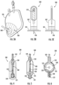
- a top view of an imaging chamber 500 is provided, in accordance with an example embodiment.
- the imaging chamber 500 does not include a seal-breaking mechanism 535.
- a mixing device 540 such as a helix mixer, is provided to prevent the contrast-enhancing agent 521 from escaping the reservoir 520.
- the mixing device 540 may increase the turbulence of the flow of the fluid sample 108 and may increase the amount of mixing of the contrast-enhancing agent 521 with the fluid sample 108.
- the imaging chamber 500 is configured to receive the flow of the fluid sample 108 at the end of a tube 102.
- the imaging chamber 500 includes a seal-breaking mechanism 535 that is configured to break the encapsulation 530. More specifically, the seal-breaking mechanism 535 can include a puncturing mechanism 536, such as a needle, that extends from a button 545. The seal-breaking mechanism 535 can be configured to puncture the tube 102 and an encapsulation 530 of the contrast-enhancing agent 521.
- the imaging chamber 500 can be configured to receive the tube 102 and be snapped onto the tube 102 by pressing down on a button 545 of the imaging chamber 500. Pushing the button 545 can also cause the puncturing mechanism 536 to move towards and puncture the tube 102 and the encapsulation 530 of the contrast-enhancing agent 521.
- the puncturing mechanism 536 can be hollow and can include one or more inlets that allow the fluid sample 108 to enter the puncturing mechanism 536 and flow to the channel 550. Once the fluid sample 108 is within the channel 550, the fluid sample can mix with the fluid sample 108.
- the imaging chamber 500 includes a seal-breaking mechanism 535 that is configured to break the encapsulation 530.
- the seal-breaking mechanism 535 can include a puncturing mechanism 536, such as a needle, that extends from a button 545.
- the button 545 can be rotatably coupled to the body of the imaging chamber 500 with a hinge 551.
- the puncturing mechanism 536 can be configured to puncture an encapsulation 530 of the contrast-enhancing agent 521.
- the imaging chamber 500 can be configured to receive the tube 102 and be snapped onto the tube 102 by pressing down on a button 545 of the imaging chamber 500.
- Pushing the button 545 can also cause the puncturing mechanism 536 to move towards and puncture the tube 102 and the encapsulation 530 of the contrast-enhancing agent 521.
- the puncturing mechanism 536 can be hollow and can include one or more inlets that allow the fluid sample 108 to enter the puncturing mechanism 536 and flow to the channel 550. Once the fluid sample 108 is within the channel 550, the fluid sample can mix with the fluid sample 108.
- the imaging chamber 500 includes a seal-breaking mechanism 535 that is on the bottom of the button 545 and is configured to break the encapsulation 530. More specifically, the seal-breaking mechanism 535 can include a puncturing mechanism 536, such as a needle, that extends from the button 545.
- the button 545 can be rotatably coupled to the body of the imaging chamber 500 with a hinge 551.
- the puncturing mechanism 536 can be configured to puncture an encapsulation 530 of the contrast-enhancing agent 521.
- the imaging chamber 500 can be configured to receive the tube 102 the button 545 can be pushed to cause the puncturing mechanism 536 to move towards and puncture the tube 102 and the encapsulation 530 of the contrast-enhancing agent 521.
- the puncturing mechanism 536 can be hollow and can include one or more inlets that allow the fluid sample 108 to enter the puncturing mechanism 536 and flow to the channel 550. Once the fluid sample 108 is within the channel 550, the fluid sample can mix with the fluid sample 108, forming the fluid mixture 536.
- FIG. 14 a top view of an imaging chamber 500 is provided, in accordance with an example embodiment.
- the imaging chamber 500 includes a seal-breaking mechanism 535 (not shown) that is configured to break the encapsulation 530.
- the seal breaking mechanism 535 of FIG. 14 can operate the same as or similarly to the seal breaking mechanism 535 of FIGS. 13A and 13B .
- the imaging chamber 500 can be housed within a collection device 103. Incorporating the imaging chamber 500 within a collection device 103 can increase the ease of handling the imaging chamber 500 because the imaging chamber 500 may be relatively small. Also, in this example, the imaging chamber 500 is configured to be in line with the tube 102.
- FIG. 15 a top view of an imaging chamber 500 is provided, in accordance with an example embodiment.
- the imaging chamber 500 includes a seal-breaking mechanism 535 (not shown) that is configured to break the encapsulation 530.
- the seal breaking mechanism 535 of FIG. 14 can operate the same as or similarly to the seal breaking mechanism 535 of FIGS. 13A and 13B .
- a top view of an imaging chamber 500 is provided, in accordance with an example embodiment.
- the imaging chamber 500 does not include a seal-breaking mechanism 535 that is configured to break the encapsulation 530.
- the fluid sample 108 flows towards and through the reservoir 520 that stores the contrast-enhancing agent 521.
- the fluid sample 108 mixes with the contrast-enhancing agent 521, forming the fluid mixture 556.
- the fluid mixture 556 then flows towards the imaging window 510, which is positioned downstream from the reservoir 520.
- the imaging system 400 includes an illumination device 402 and an imaging device 406.
- the imaging system 400 can be configured to receive an imaging chamber 500.
- the imaging chamber 500 can include an imaging window 510 that can be optically clear, or substantially optically clear.
- the imaging window 510 can comprise a transparent, or substantially transparent, material, such as glass or a clear polymer.
- the imaging chamber 500 may define a hollow portion that forms the flow channel 550.
- the flow channel 550 within the imaging chamber 500 may be in the form of a cavity that is between an upper substrate 509 and a lower substrate 511.
- the flow channel 550 provides a passageway for a fluid mixture 556 to flow inside the imaging chamber 500 and to the imaging window 510.
- the imaging chamber 500 is removable or replaceable. For example, the imaging chamber 500 may be removed from the imaging system 400 and replaced after each use.
- the fluid mixture 556 can include a fluid sample 108, such as a PD effluent, and a contrast-enhancing agent 521.
- the fluid mixture 556 may comprise additional or alternative fluid samples other than the PD effluent.
- the fluid mixture 556 can include urine.
- the fluid sample 108 can include oil.
- the fluid sample 108 can include blood.
- the fluid sample 108 can include joint fluid.
- the imaging system 400 can include an illumination device 402.
- the illumination device 402 can be configured to produce, generate, emit, and/or trigger the production, generation, and/or emission of light.
- the example illumination device 402 may include, but is not limited to, laser diodes (for example, UV, visible, or IR laser diodes, edge-emitting laser diodes, surface-emitting laser diodes, and/or the like). Additionally, or alternatively, the illumination device 402 may comprise one or more light-emitting diodes (LEDs). Additionally, or alternatively, the illumination device 402 may comprise one or more other forms of natural and/or artificial sources of light.
- laser diodes for example, UV, visible, or IR laser diodes, edge-emitting laser diodes, surface-emitting laser diodes, and/or the like.
- the illumination device 402 may comprise one or more light-emitting diodes (LEDs). Additionally, or alternatively, the illumination device 402 may comprise one or more other forms of natural
- At least one illumination device 402 is configured to emit at least one light beam.
- the at least one light beam emitted by the at least one illumination device 402 may comprise coherent light.
- coherent light refers to a light beam where the wavefront has a synchronized phase.
- coherent light include, but are not limited to, laser light.
- the light beam in laser light has the same frequency and phase.
- the at least one illumination device 402 includes, but is not limited to, laser diodes (for example, UV, visible, or IR laser diodes, edge-emitting laser diodes, surface-emitting laser diodes, and/or the like).
- the at least one light beam emitted by the at least one illumination device 402 may comprise incoherent light or at least partially incoherent light.
- incoherent light refers to a light beam where the wavefront does not have a synchronized phase.
- incoherent light does not contain photons with the same frequency and does not have wavelengths that are in phase with one another.
- the at least one illumination device 402 includes, but is not limited to, light-emitting diodes (LEDs) or lamps.
- the illumination device 402 is positioned above the imaging chamber 500.
- the illumination device 402 can be positioned above and aligned with the imaging window 510 of the imaging chamber 500.
- At least one light beam emitted by the illumination device 402 can be directed to a top surface of the imaging chamber 500.
- the at least one light beam can pass through the imaging window 510 and through the fluid mixture 556 that is within the flow channel 550 of the imaging chamber 500.
- the at least one light beam can also pass through the lower substrate 511 and to the imaging device 406 that is positioned under the imaging chamber 500.
- the imaging device 406 includes an image sensor that generates digital holography image data associated with the fluid mixture 556 in the flow channel 550 of the imaging chamber 500.
- digital holography image data refers to image data that is generated based on digital holography techniques, including, but not limited to, lensless holography techniques.
- the digital holography image data may be generated by the image sensor without any imaging lenses and without any adjustments, such as optomechanical focusing adjustments. In such an example, there are no imaging lenses between the bottom surface of the imaging chamber 500 and the image sensor.
- the digital holography image data may comprise a digital holography image of the fluid mixture 556 (for example, a digital holography image of various particles, cells, etc. in the fluid mixture 556).
- the image sensor may comprise one or more imagers and/or image sensors.
- Various examples of the image sensor may include, but are not limited to, a charge-coupled device (CCD), a complementary metal-oxide semiconductor (CMOS) sensor, and/or the like.
- the image sensor does not comprise any lenses so as to generate digital holography image data based on lensless holography techniques.
- an example fluid sample 108 imaging system 400 may implement other imaging techniques.
- example embodiments of the present disclosure may implement optical microscopy as the imaging technique.
- example embodiments of the present disclosure may implement ultraviolet (UV) fluorescence as the imaging technique.
- UV ultraviolet
- the description above provides an example positional arrangement between the illumination device 402 and the imaging chamber 500 and an example positional arrangement between the imaging chamber 500 and the imaging device 406, it is noted that the scope of the present disclosure is not limited to the description above.
- the illumination device 402, the imaging chamber 500, and/or the imaging device 406 of an example imaging system 400 may be positioned differently than those shown in FIG. 17 .
- the illumination device 402 may be positioned under the imaging chamber 500, and the imaging device 406 may be positioned above the imaging chamber 500.
- the method can include a step 910 of receiving a fluid sample 108, such as PD effluent, that comprises biological cells, such as red blood cells and/or white blood cells, into an imaging chamber 500.
- the imaging chamber 500 can include a contrast-enhancing agent 521.
- the imaging chamber 500 can include the contrast-enhancing agent 521 prior to the imaging chamber 500 receives the fluid sample 108.
- the method 900 can include a step 920 of mixing the fluid sample 108 with the contrast-enhancing agent 521 to form the fluid mixture 556.
- the imaging chamber 500 can be shaken or agitated by hand or by machine.
- the imaging chamber 500 can include a mixing device 540 to increase the turbulence of the flow of the fluid sample 108, which may increase the mixing of the fluid sample 108 with the contrast-enhancing agent 521.
- the step 920 of mixing the fluid sample 108 with the contest-enhancing agent 521 can be done outside of an imaging system 400, by hand or by machine, or within the imaging system 400, by machine.
- the imaging system 400 includes an agitation device to shake or agitate the imaging chamber 500.
- the method 900 can include a step 930 of imaging the fluid mixture 556 that is within the imaging chamber 500 with the imaging system 400.
- an imaging device 406 in conjunction with an illumination device 402, can image the fluid mixture 556.
Landscapes
- Health & Medical Sciences (AREA)
- Life Sciences & Earth Sciences (AREA)
- Engineering & Computer Science (AREA)
- Physics & Mathematics (AREA)
- General Health & Medical Sciences (AREA)
- Heart & Thoracic Surgery (AREA)
- Medical Informatics (AREA)
- Pathology (AREA)
- Biomedical Technology (AREA)
- Animal Behavior & Ethology (AREA)
- Public Health (AREA)
- Veterinary Medicine (AREA)
- General Physics & Mathematics (AREA)
- Biophysics (AREA)
- Optics & Photonics (AREA)
- Surgery (AREA)
- Molecular Biology (AREA)
- Chemical & Material Sciences (AREA)
- Computer Vision & Pattern Recognition (AREA)
- Radiology & Medical Imaging (AREA)
- Theoretical Computer Science (AREA)
- Nuclear Medicine, Radiotherapy & Molecular Imaging (AREA)
- Immunology (AREA)
- Emergency Medicine (AREA)
- Hematology (AREA)
- Anesthesiology (AREA)
- Biochemistry (AREA)
- Analytical Chemistry (AREA)
- Dispersion Chemistry (AREA)
- Vascular Medicine (AREA)
- Urology & Nephrology (AREA)
- High Energy & Nuclear Physics (AREA)
- Quality & Reliability (AREA)
- Physiology (AREA)
- Spectroscopy & Molecular Physics (AREA)
- Medicines Containing Antibodies Or Antigens For Use As Internal Diagnostic Agents (AREA)
- Ultra Sonic Daignosis Equipment (AREA)
- Magnetic Resonance Imaging Apparatus (AREA)
Applications Claiming Priority (1)
| Application Number | Priority Date | Filing Date | Title |
|---|---|---|---|
| US18/176,883 US20240296589A1 (en) | 2023-03-01 | 2023-03-01 | Imaging chamber for an imaging system |
Publications (2)
| Publication Number | Publication Date |
|---|---|
| EP4424236A2 true EP4424236A2 (de) | 2024-09-04 |
| EP4424236A3 EP4424236A3 (de) | 2024-11-13 |
Family
ID=89771550
Family Applications (1)
| Application Number | Title | Priority Date | Filing Date |
|---|---|---|---|
| EP24154918.7A Pending EP4424236A3 (de) | 2023-03-01 | 2024-01-31 | Abbildungskammer für ein abbildungssystem |
Country Status (2)
| Country | Link |
|---|---|
| US (1) | US20240296589A1 (de) |
| EP (1) | EP4424236A3 (de) |
Family Cites Families (8)
| Publication number | Priority date | Publication date | Assignee | Title |
|---|---|---|---|---|
| US6575930B1 (en) * | 1999-03-12 | 2003-06-10 | Medrad, Inc. | Agitation devices and dispensing systems incorporating such agitation devices |
| US20060263888A1 (en) * | 2000-06-02 | 2006-11-23 | Honeywell International Inc. | Differential white blood count on a disposable card |
| US8382704B2 (en) * | 2006-12-29 | 2013-02-26 | Medrad, Inc. | Systems and methods of delivering a dilated slurry to a patient |
| US9222935B1 (en) * | 2015-05-28 | 2015-12-29 | Pixcell Medical Technologies Ltd | Fluid sample analysis system |
| US11079719B2 (en) * | 2017-07-05 | 2021-08-03 | Accelerate Diagnostics, Inc. | Lens-free holographic optical system for high sensitivity label-free microbial growth detection and quantification for screening, identification, and susceptibility testing |
| EP3906413A4 (de) * | 2019-01-03 | 2022-11-16 | Pixcell Medical Technologies Ltd. | Systeme und verfahren zur analyse einer flüssigkeitsprobe |
| TW202208005A (zh) * | 2020-07-01 | 2022-03-01 | 新加坡商阿瓦克科技私人有限公司 | 腹膜透析分析裝置 |
| WO2022165270A1 (en) * | 2021-01-29 | 2022-08-04 | The Board Of Trustees Of The Lelandstanford Junior University | Devices, systems, and methods for detecting peritonitis |
-
2023
- 2023-03-01 US US18/176,883 patent/US20240296589A1/en active Pending
-
2024
- 2024-01-31 EP EP24154918.7A patent/EP4424236A3/de active Pending
Also Published As
| Publication number | Publication date |
|---|---|
| EP4424236A3 (de) | 2024-11-13 |
| US20240296589A1 (en) | 2024-09-05 |
Similar Documents
| Publication | Publication Date | Title |
|---|---|---|
| RU2516529C2 (ru) | Модифицированный многофункциональный пробоотборный контейнер | |
| RU2365919C2 (ru) | Способ, устройство и система для волюметрического подсчета белых клеток крови | |
| EP2131892B1 (de) | Vorrichtung und verfahren für den nachweis von peritonitis im frühstadium mit selbstreinigender abflusskammer | |
| CN102216954B (zh) | 用于分析液体样本中的微粒的方法和装置 | |
| AU2008286252B2 (en) | Apparatus and methods for early stage peritonitis detection and for in vivo testing of bodily fluids | |
| AU2011223342B2 (en) | Flexible sample container | |
| US11906410B2 (en) | Cell inspection device and cell inspection method | |
| JP2004305173A (ja) | 細菌測定方法と装置とプログラム | |
| KR20090015114A (ko) | 혈소판들의 계산 | |
| JP2007298502A (ja) | 血球分離用フィルター | |
| DE112008002138T5 (de) | Verfahren zum Messen von Chemilumineszenz und Vorrichtung zum Messen von Chemilumineszenz | |
| CN104422646B (zh) | 样本分析方法及样本分析装置 | |
| CA2886057A1 (en) | Portal and method for management of dialysis therapy | |
| US20240296589A1 (en) | Imaging chamber for an imaging system | |
| WO2017130862A1 (ja) | 生体試料撮像装置及び生体試料撮像方法 | |
| JP2006038512A (ja) | 血液濾過用ガラス繊維フィルター、血液濾過器具および血液分析素子 | |
| JP7175231B2 (ja) | 検体の分析方法及び検体の分析装置 | |
| CN112513631A (zh) | 细胞检查装置和细胞检查方法 | |
| JPH10197440A (ja) | 粒子分析装置 | |
| JP4509526B2 (ja) | 細菌分析装置および方法 | |
| EP2197511B1 (de) | Vorrichtung für den nachweis von peritonitis im frühstadium | |
| US20260069256A1 (en) | Medical drain bag and imaging slide | |
| DE102009001455B4 (de) | Probenahmevorrichtung und -verfahren | |
| JP6100472B2 (ja) | 測定装置、透析終了条件判定装置、および透析経過提示装置 | |
| JP3399645B2 (ja) | 便内潜血検出装置 |
Legal Events
| Date | Code | Title | Description |
|---|---|---|---|
| PUAI | Public reference made under article 153(3) epc to a published international application that has entered the european phase |
Free format text: ORIGINAL CODE: 0009012 |
|
| STAA | Information on the status of an ep patent application or granted ep patent |
Free format text: STATUS: REQUEST FOR EXAMINATION WAS MADE |
|
| 17P | Request for examination filed |
Effective date: 20240131 |
|
| AK | Designated contracting states |
Kind code of ref document: A2 Designated state(s): AL AT BE BG CH CY CZ DE DK EE ES FI FR GB GR HR HU IE IS IT LI LT LU LV MC ME MK MT NL NO PL PT RO RS SE SI SK SM TR |
|
| PUAL | Search report despatched |
Free format text: ORIGINAL CODE: 0009013 |
|
| AK | Designated contracting states |
Kind code of ref document: A3 Designated state(s): AL AT BE BG CH CY CZ DE DK EE ES FI FR GB GR HR HU IE IS IT LI LT LU LV MC ME MK MT NL NO PL PT RO RS SE SI SK SM TR |
|
| RIC1 | Information provided on ipc code assigned before grant |
Ipc: G01N 15/01 20240101ALI20241004BHEP Ipc: A61M 1/28 20060101ALI20241004BHEP Ipc: A61B 5/1455 20060101ALI20241004BHEP Ipc: A61B 5/145 20060101AFI20241004BHEP |