EP4424136A1 - Mäher mit schnurtrommel - Google Patents
Mäher mit schnurtrommel Download PDFInfo
- Publication number
- EP4424136A1 EP4424136A1 EP22946042.3A EP22946042A EP4424136A1 EP 4424136 A1 EP4424136 A1 EP 4424136A1 EP 22946042 A EP22946042 A EP 22946042A EP 4424136 A1 EP4424136 A1 EP 4424136A1
- Authority
- EP
- European Patent Office
- Prior art keywords
- cord
- reels
- cords
- stopper
- nylon
- Prior art date
- Legal status (The legal status is an assumption and is not a legal conclusion. Google has not performed a legal analysis and makes no representation as to the accuracy of the status listed.)
- Withdrawn
Links
Images



Classifications
-
- A—HUMAN NECESSITIES
- A01—AGRICULTURE; FORESTRY; ANIMAL HUSBANDRY; HUNTING; TRAPPING; FISHING
- A01D—HARVESTING; MOWING
- A01D34/00—Mowers; Mowing apparatus of harvesters
- A01D34/01—Mowers; Mowing apparatus of harvesters characterised by features relating to the type of cutting apparatus
- A01D34/412—Mowers; Mowing apparatus of harvesters characterised by features relating to the type of cutting apparatus having rotating cutters
- A01D34/416—Flexible line cutters
-
- A—HUMAN NECESSITIES
- A01—AGRICULTURE; FORESTRY; ANIMAL HUSBANDRY; HUNTING; TRAPPING; FISHING
- A01D—HARVESTING; MOWING
- A01D34/00—Mowers; Mowing apparatus of harvesters
- A01D34/01—Mowers; Mowing apparatus of harvesters characterised by features relating to the type of cutting apparatus
- A01D34/412—Mowers; Mowing apparatus of harvesters characterised by features relating to the type of cutting apparatus having rotating cutters
- A01D34/416—Flexible line cutters
- A01D34/4166—Mounting or replacement of the lines
-
- A—HUMAN NECESSITIES
- A01—AGRICULTURE; FORESTRY; ANIMAL HUSBANDRY; HUNTING; TRAPPING; FISHING
- A01D—HARVESTING; MOWING
- A01D34/00—Mowers; Mowing apparatus of harvesters
- A01D34/01—Mowers; Mowing apparatus of harvesters characterised by features relating to the type of cutting apparatus
- A01D34/412—Mowers; Mowing apparatus of harvesters characterised by features relating to the type of cutting apparatus having rotating cutters
- A01D34/416—Flexible line cutters
- A01D34/4161—Means for feeding cutter line
-
- A—HUMAN NECESSITIES
- A01—AGRICULTURE; FORESTRY; ANIMAL HUSBANDRY; HUNTING; TRAPPING; FISHING
- A01D—HARVESTING; MOWING
- A01D34/00—Mowers; Mowing apparatus of harvesters
- A01D34/01—Mowers; Mowing apparatus of harvesters characterised by features relating to the type of cutting apparatus
- A01D34/412—Mowers; Mowing apparatus of harvesters characterised by features relating to the type of cutting apparatus having rotating cutters
- A01D34/416—Flexible line cutters
- A01D34/4167—Protection devices
-
- A—HUMAN NECESSITIES
- A01—AGRICULTURE; FORESTRY; ANIMAL HUSBANDRY; HUNTING; TRAPPING; FISHING
- A01D—HARVESTING; MOWING
- A01D34/00—Mowers; Mowing apparatus of harvesters
- A01D34/01—Mowers; Mowing apparatus of harvesters characterised by features relating to the type of cutting apparatus
- A01D34/412—Mowers; Mowing apparatus of harvesters characterised by features relating to the type of cutting apparatus having rotating cutters
- A01D34/416—Flexible line cutters
- A01D34/4168—Constructional details of the flexible lines
Definitions
- This invention relates to a grass cutter with a cord reel that can be attached to the grass cutter.
- a grass cutter also called a grass mower
- a grass cutter that has a motor, a shaft, and a rotary saw, and that the user operates a handle fixed to the shaft to cut grass and trees with thin trunks.
- a plastic cord such as a thick nylon cord is attached to the rotor part of the grass cutter where the rotary saw is attached, instead of the rotary saw, and used as a cord cutter for cutting grass (see Patent Literature 1).
- Patent Literature 1 Japanese Patent Application Laid-open No. 2014-150765
- the replacement nylon cord In the case of a type of grass cutter that uses a long nylon cord, the replacement nylon cord is usually sold on the market wound on a reel. Therefore, the user must remove the replacement nylon cord from the reel and attach it to the rotor of the grass cutter in a prescribed procedure. This is a time-consuming and labor-intensive process that also requires familiarity. In addition, the type that uses a pre-cut short nylon cord is more expensive per unit length than the type that uses a long nylon cord, resulting in a larger economic burden.
- grass cutters that use a long nylon cord rotate two cord cutters to cut the grass.
- one long nylon cord is wound onto a reel from its center portion, and both ends of the single nylon cord are pulled out from the reel and used as two cord cutters.
- both ends of the nylon cord are inevitably pulled out when the nylon cord is withdrawn from the reel, resulting in two cord cutters being extended simultaneously, and each The length of each cord cutter cannot be adjusted independently.
- the purpose of this invention is to provide a grass cutter that uses a cord (cord cutter) such as a long nylon cord wound on a reel, where the user can easily replace the cord, and where the length of the two cords can be easily adjusted.
- a cord cord cutter
- a grass cutter including:
- the two cord reels are individually removable in the housing space formed inside the cover member. Therefore, the user can replace the two cord reels individually as needed.
- each of the two cord reels has a top wall and a bottom wall facing each other in the vertical direction. Therefore, even when the two cord reels are placed on top of each other, the lower wall of one cord reel and the upper wall of the other cord reel act as a barrier, and there is no risk of the two cords wounding the two cord reels becoming entangled.
- two cord adjustment mechanisms are provided on the cover member so that the user can easily adjust the cord length.
- two cord adjustment mechanisms correspond to the two cord reels, and the two cords are connected to different cord adjustment mechanisms. Therefore, the lengths of the two cords can be adjusted independently.
- the two cord reels are arranged to rotate independently of each other, so even if one cord reel rotates accordingly when the length of the nylon cord drawn from one cord reel is being adjusted, it will not affect the other cord reel.
- the grass cutter 10 has a cylindrical rod 20, a rotor section 30 provided at one end of the rod 20, a drive section 40 provided at the end of the rod 20 opposite the rotor section 30, a handle 50 located on the side of the rod 20 near the drive section 20, and a guard 60 located on the side of the rod 20 near the rotor section 30.
- the cylindrical rod 20 is a hollow metal pipe about 1500 mm to 1700 mm long.
- the drive section 40 is attached at an upper end of the rod 20.
- the drive section 40 has a motor 41 and a battery 42 for supplying power to the motor 41.
- Rotation of a rotary shaft 43 of the motor 41 is transmitted to the rotor section 30 via an unshown transmission mechanism provided inside the rod 20.
- the rotor section 30 includes: a shaft 31 configured to rotate by the rotational drive force transmitted from the rotational shaft 43 of the motor 41 through the transmission mechanism; an upper cover 32 and a lower cover 33 which are fixed to the shaft 31 and rotating with the shaft 31; and two cord reels 120, 130.
- the handle 50 is a handle for the user to grasp the grass cutter 10 and has an abbreviated U-shape.
- a switch 51 linked to the motor 41 is attached to one end of the handle 50, and while the user turns on the switch 51, the motor 41 is driven to rotate the rotor section 30.
- the upper cover 32 of the rotor section 30 is a metal cover member. As shown in FIG. 2 , it has a side wall 320 of cylindrical shape and a circular upper wall 321 covering the upper part of the side wall 320. A hole is formed in the center of the upper wall 321 through which a shaft 31 is inserted. The shaft 31 is threaded with a male thread, and the upper cover 32 inserted into the shaft 31 is secured to the shaft 31 by a nut or other fastening member.
- the lower cover 33 of the rotor section 30 is also a metal cover member, and has a side wall 330 of an abbreviated cylindrical shape and a circular lower wall 331 covering the lower part of the side wall 330.
- the lower cover 33 is fixed to the lower part of the upper cover 32 by screwing or otherwise, so as to cover the upper cover 32 from below.
- a cylindrical space is formed inside the upper cover 32 and lower cover 33 to contain the cord reels 120 and 130.
- the upper cover 32 can be fixed to the shaft 31. Furthermore, since the upper cover 32 and the lower cover 33 are fixed to each other with screws, etc., not only the upper cover 32 but also the lower cover 33 rotates as the shaft 31 rotates.
- the side wall 320 of the upper cover 32 has two guide holes 323 (see FIG. 4 ) for taking out the nylon cords 200 of the cord reels 120 and 130, as described below.
- the cord reels 120 and 130 which are arranged inside the space formed by the upper cover 32 and the lower cover 33 of the rotor section 30, will be described with reference to the drawings.
- the cord reel 130 is arranged below the cord reel 120.
- the cord reels 120 and 130 have similar configurations.
- the cord reels 120 and 130 have covers 121 and 131 with hollow housing chambers.
- the cover 121 has an upper wall 121U, a lower wall 121D, and an axis-portion 121P that connects the upper and lower walls 121U and 121D in a vertical direction.
- the cover 131 has an upper wall 131U, a lower wall 131D, and an axis-portion 131P that connects the upper wall 131U and the lower wall 131D in the vertical direction.
- the axis-portions 121P and 131P are provided in the covers 121 and 131, thereby forming through holes 121H and 131H in the covers 121 and 131 that pass through the upper walls 121U and 131U and the lower walls 121D and 131D in the vertical direction.
- the covers 121 and 131 have a doughnut shape with the central portion of a cylinder hollowed out.
- One nylon cord 200 is wound around each of the hollow housing chambers inside the covers 121 and 131.
- a hole or slit (not shown) is formed in the outer circumference of the cover 121 to take out the nylon cord 200.
- the lower wall 121D of cord reel 120 and the upper wall 131U of cord reel 130 may be in contact with each other, or they may be arranged to face each other, separated by a predetermined gap. In either case, the cord reel 120 and the cord reel 130 are arranged to rotate independently of each other.
- the two nylon cords 200 drawn from the cord reels 120 and 130 are drawn through two body guide holes 323 in the side wall 320 of the upper cover 32.
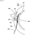
- a cord adjustment mechanism 400 is provided near the body guide holes 323 in the side wall 320 of the upper cover 32.
- the cord adjustment mechanism 400 has a pair of gears (a first gear 411 and a second gear 412) provided on the upper cover 32 and an unshown locking portion that locks the rotation of the first gear 411.
- the first gear 411 and the second gear 412 are aligned vertically, and a nylon cord 200 is sandwiched between the first gear 411 and the second gear 412.
- the upper portion of the first gear 411 is exposed from the top surface of the upper cover 32, and the user can feed or retract the nylon cord 200 toward the body guide hole 323 by turning the upper portion of the first gear 411. This allows the user to properly adjust the length of the nylon cord 200 drawn out of the body guide hole 323 (see FIG. 5 ).
- the rotation of the first gear 411 can be locked by an unshown locking mechanism to fix the length of the nylon cord 200 drawn out of the body guide hole 323. With the length of the nylon cord 200 fixed, the motor can be driven to rotate the shaft 31 to rotate the nylon cord 200 for mowing.
- the tip of the nylon cord 200 gradually wears out when the grass cutter 10 is used to cut the grass.
- the user can purchase and replace the cord reels 120 and 130 on which the nylon cord 200 is wound.
- the two cord reels 120 and 130 can be replaced at the same time. It is also possible to replace only one of the two cord reels 120 and 130.
- the case of replacing two cord reels 120 and 130 will be used as an example.
- the screws between the upper cover 32 and the lower cover 33 is removed, and the lower cover 33 is removed from the upper cover 32.
- the cord reel 120 to be replaced is removed from the upper cover 32.
- new cord reels 120 and 130 are prepared and the cord reels 120 and 130 are attached to the upper cover 32.
- two nylon cords 200 are pulled out at an appropriate length from the take-out holes of covers 121 and 131, and each nylon cord 200 is passed between the first gear 411 and the second gear 412 of the cord adjustment mechanism 400 to attach the cord reels 120 and 130 to the upper cover 32. Furthermore, the nylon cord 200 is pulled out from the guide hole 323 of the upper cover 32.
- the length of the nylon cord 200 pulled out of the guide hole 323 is adjusted to an appropriate length.
- the lower cover 33 is then mounted to cover the upper cover 32 from below and screwed down to secure the lower cover 33 to the upper cover 32.
- the first gear 411 is then locked so that the first gear 411 will not inadvertently rotate.
- the nylon cord 200 is wound on the cord reels 120 and 130, so the user can easily replace the nylon cord 200 with the entire cord reel 120 and 130. In doing so, the user does not have to wind the long nylon cord around the rotor part of the grass cutter as with conventional grass cutters, which saves time and effort for the user and allows easy replacement of the nylon cord even for users who are not familiar with machine operation. Also, when the user wants to use a nylon cord of a different thickness, he/she only needs to replace the entire cord reels 120 and 130, which saves a great deal of time and effort compared to conventional grass cutters. In addition, the two cord reels 120 and 130 are not integrated so that they are connected to each other, but can be removed and replaced individually. Therefore, the two cord reels 120 and 130 do not necessarily need to be replaced at the same time, and only one of them can be replaced, allowing the cord to be used without waste.
- the replaceable cord reels 120 and 130 are covered by the metal upper cover 32 and the metal lower cover 33, so that even if small stones or other objects fly into the cord reels 120 and 130 during the work of mowing the grass, they may not directly hit the cord reels 120, 130. Therefore, there is no need to form the covers 121, 131 of the cord reels 120, 130 with metal materials, etc., and the covers 121, 131 of the cord reels 120, 130 can be formed with lightweight materials such as plastic or resin, for example, to reduce weight and cost.
- the two cord reels 120 and 130 are individually removable in the compartment formed by the upper cover 32 and lower cover 33. Therefore, the user can replace the cord reels 120 and 130 individually.
- the cord reels 120 and 130 each have an upper wall 121U, 131U and a lower wall 121D, 131D, respectively, facing each other in the vertical direction. Therefore, when the cord reel 130 is placed on top of the cord reel 120, the lower wall 121D of the cord reel 120 and the upper wall 131U of the cord reel 130 act as a barrier and there is no risk of the two nylon cords 200 getting tangled.
- two cord adjustment mechanisms 400 are provided on the upper cover 32 so that the user can easily adjust the length of the nylon cord 200.
- the grass cutter for the present invention is also provided with two cord adjustment mechanisms 400 corresponding to the two cord reels 120 and 130.
- the two nylon cords 200 are connected to separate cord adjustment mechanisms 400. Therefore, the lengths of the two nylon cords 200 can be adjusted independently.
- the two cord reels 120 and 130 are arranged to rotate independently of each other, so that even if one cord reel rotates accordingly when the length of the nylon cord drawn from one cord reel is being adjusted, it will not affect the other cord reel.
- the cord reels 120 and 130 were wound with nylon cords 200, but they do not necessarily have to be made of nylon, and cords formed of other resins or the like may be used.
- the outer shape of the cord reels 120 and 130 does not necessarily have to be doughnut-shaped, and can be made into any appropriate shape.
- the cord reels 120, 130 were provided with covers 121, 131, and the nylon cords 200 were housed in hollow accommodation chambers inside the covers 121, 131.
- the cord reels 120 and 130 do not necessarily have to be provided with covers 121 and 131 with hollow accommodation chambers.
- covers 121 and 131 may, for example, have a nylon cord 200 wound around a spool (winding frame) as long as it has a portion corresponding to the upper and lower walls and the axis-portion.
- the cord reels 120 and 130 can be shaped as desired, so, for example, commercially available replacement cord reels can be used as they are.
- the two cord adjustment mechanisms 400 were provided on the upper cover 32, but they need not necessarily be provided on the upper cover 32, and may be provided on the lower cover 33.
- the configuration of the cord adjustment mechanism 400 is not necessarily limited to the configuration of the above embodiment, but may be realized by other configurations as long as it has a function to adjust and fix the length of the nylon cord 200 drawn from the cord reels 120 and 130.
- Other configurations of the cord adjustment mechanism 400 will be described below with examples, but the invention is not limited to these examples.
- a wheel with a non-slip surface such as rubber can be used.
- the configuration of the cord adjustment mechanism 400 is not limited to a mechanism that adjusts the length of the nylon cord 200 as the gear or wheel with non-slip surface rotates, but can be a mechanism that adjusts the length of the nylon cord 200 as it slides along, such as a slider.
- the cord adjustment mechanism 450 may have a stopper 451 that moves vertically to a contacting position that contacts the nylon cord 200 and a separating position that moves away from the nylon cord 200, and a contacting portion 452 that faces the stopper 451 at the bottom of the stopper 451,
- the stopper 451 may have a locking portion 453 that secures the stopper 451 in the contacting position.
- the locking section 453 has a locking pin 453a that moves horizontally, and the side of the stopper 451 has a hole 451a into which the locking pin 453a is inserted.
- the stopper 451 is provided with a spring 451b.
- the nylon cord 200 With the stopper 451 pushed into the tangent position against the spring 451b and the lock pin 453a inserted into the hole 451a, the nylon cord 200 can be clamped and secured between the stopper 451 and the contacting portion 452. By pulling the lock pin 453a out of the hole 451a and pushing the stopper 451 up to the release position with the spring 451b, the nylon cord 200 can be freely moved between the stopper 451 and the contacting portion 452.
- the cord adjustment mechanism 480 may have a lever 481 that rotates around an axis 483 to a contacting position and a separating position, and a contacting portion 485 that faces the base end 482 of the lever 481 in the contacting position.
- the contacting position is the position of the lever 481 indicated by the solid line in FIG. 7 , where the base end 482 of the lever 481 is in contact with the nylon cord 200.
- the separating position is the position of the lever 481 indicated by the dotted line in FIG. 7 , and is the position where the base end 482 of the lever 481 is separated from the nylon cord 200.
- the contacting portion 485 is an elastic member such as a plate spring or rubber.
- a guides 491 and a guide 492 that guide the nylon cord 200 drawn from the cord reel 120 downward may be provided on the upper cover 32. This allows the height difference between the nylon cord 200 drawn from the cord reel 130 and the nylon cord 200 drawn from the cord reel 120 to be controlled and guided into the guide hole 323 in the body.
- the cord adjustment mechanism 480 is omitted.
- the grass cutter 10 was equipped with a battery 42 and was driven by electric power, but the invention is not limited to such a manner and may be driven by an engine, for example.
Landscapes
- Life Sciences & Earth Sciences (AREA)
- Environmental Sciences (AREA)
- Harvester Elements (AREA)
Applications Claiming Priority (1)
| Application Number | Priority Date | Filing Date | Title |
|---|---|---|---|
| PCT/JP2022/044641 WO2024116420A1 (ja) | 2022-12-03 | 2022-12-03 | コードリールを備える刈払機 |
Publications (2)
| Publication Number | Publication Date |
|---|---|
| EP4424136A1 true EP4424136A1 (de) | 2024-09-04 |
| EP4424136A4 EP4424136A4 (de) | 2025-03-05 |
Family
ID=86538308
Family Applications (1)
| Application Number | Title | Priority Date | Filing Date |
|---|---|---|---|
| EP22946042.3A Withdrawn EP4424136A4 (de) | 2022-12-03 | 2022-12-03 | Mäher mit schnurtrommel |
Country Status (5)
| Country | Link |
|---|---|
| US (1) | US20250098572A1 (de) |
| EP (1) | EP4424136A4 (de) |
| JP (1) | JP7282425B1 (de) |
| CN (1) | CN117440750B (de) |
| WO (1) | WO2024116420A1 (de) |
Families Citing this family (1)
| Publication number | Priority date | Publication date | Assignee | Title |
|---|---|---|---|---|
| JP7597436B1 (ja) * | 2024-03-18 | 2024-12-10 | 有限会社とまと不動産 | 刈払機及び刈払機に用いられるコードリールカセット |
Family Cites Families (16)
| Publication number | Priority date | Publication date | Assignee | Title |
|---|---|---|---|---|
| JPS5511Y2 (de) * | 1974-04-20 | 1980-01-05 | ||
| US4476632A (en) * | 1982-07-29 | 1984-10-16 | Proulx Raymond E | Multiple flail head for a rotary mower |
| DE3916009C5 (de) * | 1989-05-17 | 2007-11-22 | Fa. Andreas Stihl | Schneidkopf für ein Pflanzenschneidgerät |
| US6493671B1 (en) * | 1998-10-02 | 2002-12-10 | Motorola, Inc. | Markup language for interactive services to notify a user of an event and methods thereof |
| US7257898B2 (en) * | 2004-04-16 | 2007-08-21 | Kwik Products, Inc. | Cutting head for string trimmer |
| ITFI20050192A1 (it) * | 2005-09-13 | 2007-03-14 | Arnetoli Motor | Testina tosaerba con mezzi per la protezione del filo di taglio |
| JP4780673B2 (ja) * | 2007-04-06 | 2011-09-28 | スターテング工業株式会社 | 刈払機用ロータリーカッタ |
| US9603301B2 (en) * | 2007-08-10 | 2017-03-28 | Orlando Jerez | Weed trimming apparatus, weed trimmer head, and trimmer line retention device |
| JP4364303B2 (ja) * | 2007-09-20 | 2009-11-18 | 立郎 冨田 | 刈払機用草刈刃及び刈払機 |
| US8429886B2 (en) * | 2008-03-05 | 2013-04-30 | Starting Industrial Co., Ltd. | Rotary cutter for mower |
| JP4673443B1 (ja) * | 2010-07-19 | 2011-04-20 | カルエンタープライズ株式会社 | 刈払機用刈刃ヘッド |
| JP2013223433A (ja) * | 2012-04-19 | 2013-10-31 | Yamada Kikai Kogyo Kk | 草刈り機用回転刃およびこれを用いた草刈り機 |
| JP5959290B2 (ja) * | 2012-04-25 | 2016-08-02 | スターテング工業株式会社 | 刈払い機用ロータリカッタ |
| JP6143328B2 (ja) | 2013-02-08 | 2017-06-07 | 株式会社北村製作所 | 線状カッターの取付構造及びこれを備えた刈払機の接地体 |
| ITUB20153397A1 (it) * | 2015-09-03 | 2017-03-03 | Dragone S R L | Rotore per diserbo |
| US10709062B2 (en) * | 2018-09-25 | 2020-07-14 | Michael Ting-Kao Chang | Line trimmer and shredder apparatus |
-
2022
- 2022-12-03 EP EP22946042.3A patent/EP4424136A4/de not_active Withdrawn
- 2022-12-03 CN CN202280035413.6A patent/CN117440750B/zh active Active
- 2022-12-03 WO PCT/JP2022/044641 patent/WO2024116420A1/ja not_active Ceased
- 2022-12-03 US US18/571,872 patent/US20250098572A1/en active Pending
- 2022-12-03 JP JP2022576352A patent/JP7282425B1/ja active Active
Also Published As
| Publication number | Publication date |
|---|---|
| WO2024116420A1 (ja) | 2024-06-06 |
| CN117440750B (zh) | 2024-08-16 |
| EP4424136A4 (de) | 2025-03-05 |
| JP7282425B1 (ja) | 2023-05-29 |
| US20250098572A1 (en) | 2025-03-27 |
| JPWO2024116420A1 (de) | 2024-06-06 |
| CN117440750A (zh) | 2024-01-23 |
Similar Documents
| Publication | Publication Date | Title |
|---|---|---|
| EP3682726B1 (de) | Rasenschneidkopf und rasenschneider | |
| EP0636307B1 (de) | Gerät zum Schneiden von Pflanzen | |
| US4024635A (en) | Mowing apparatus | |
| US4916886A (en) | Cutting line head assembly for rotary cutter | |
| US4476632A (en) | Multiple flail head for a rotary mower | |
| EP2294908B1 (de) | Drehschneidwerkzeug für mäher | |
| US9743582B2 (en) | Integrated string and blade trimmer system | |
| US4091536A (en) | Rotary cutting device | |
| US8001694B2 (en) | Fixed line rotary head trimmer with quick friction rotational lock for string trimmer machine | |
| CN204069756U (zh) | 打草机 | |
| US11412656B2 (en) | Trimmer head with improved line release feature | |
| US20250098572A1 (en) | Grass cutter with cord reel | |
| US4091538A (en) | Mowing apparatus | |
| US20120066913A1 (en) | Trimmer Head with Automatic Trimmer Line Feed Mechanism | |
| JP7217485B1 (ja) | 刈払機に取り付け可能なコードリールカセット及びそれを備える刈払機 | |
| US20230000011A1 (en) | String trimmer assembly and trimmer head for use with same | |
| CA2537078A1 (en) | Vegetation trimmer apparatus | |
| US4205439A (en) | Grass cutting machine | |
| JP7597436B1 (ja) | 刈払機及び刈払機に用いられるコードリールカセット | |
| JP6461889B2 (ja) | 交換式のコードリールカセットを備える刈払機及びそれに用いる交換式コードリールカセット | |
| US12484475B2 (en) | Integrated trimmer for a lawn mower | |
| CN221689314U (zh) | 放线结构及打草机 | |
| JPH02109908A (ja) | 草刈り機用カッターヘッド | |
| JP3235933U (ja) | 刈払機用コードの取付け構造およびそれを備える刈払機 | |
| US4185380A (en) | Flexible line rotary vegetation cutter having a tension regulated line feed |
Legal Events
| Date | Code | Title | Description |
|---|---|---|---|
| STAA | Information on the status of an ep patent application or granted ep patent |
Free format text: STATUS: UNKNOWN |
|
| STAA | Information on the status of an ep patent application or granted ep patent |
Free format text: STATUS: THE INTERNATIONAL PUBLICATION HAS BEEN MADE |
|
| PUAI | Public reference made under article 153(3) epc to a published international application that has entered the european phase |
Free format text: ORIGINAL CODE: 0009012 |
|
| STAA | Information on the status of an ep patent application or granted ep patent |
Free format text: STATUS: REQUEST FOR EXAMINATION WAS MADE |
|
| 17P | Request for examination filed |
Effective date: 20231220 |
|
| AK | Designated contracting states |
Kind code of ref document: A1 Designated state(s): AL AT BE BG CH CY CZ DE DK EE ES FI FR GB GR HR HU IE IS IT LI LT LU LV MC ME MK MT NL NO PL PT RO RS SE SI SK SM TR |
|
| A4 | Supplementary search report drawn up and despatched |
Effective date: 20250203 |
|
| RIC1 | Information provided on ipc code assigned before grant |
Ipc: A01D 34/416 20060101AFI20250128BHEP |
|
| STAA | Information on the status of an ep patent application or granted ep patent |
Free format text: STATUS: EXAMINATION IS IN PROGRESS |
|
| STAA | Information on the status of an ep patent application or granted ep patent |
Free format text: STATUS: THE APPLICATION HAS BEEN WITHDRAWN |
|
| 17Q | First examination report despatched |
Effective date: 20251113 |
|
| 18W | Application withdrawn |
Effective date: 20251205 |