EP4414718A1 - Strommessvorrichtung - Google Patents
Strommessvorrichtung Download PDFInfo
- Publication number
- EP4414718A1 EP4414718A1 EP22877847.8A EP22877847A EP4414718A1 EP 4414718 A1 EP4414718 A1 EP 4414718A1 EP 22877847 A EP22877847 A EP 22877847A EP 4414718 A1 EP4414718 A1 EP 4414718A1
- Authority
- EP
- European Patent Office
- Prior art keywords
- magnetoresistors
- magnetic field
- bridge arm
- electrically connected
- bridge structure
- Prior art date
- Legal status (The legal status is an assumption and is not a legal conclusion. Google has not performed a legal analysis and makes no representation as to the accuracy of the status listed.)
- Pending
Links
Images


Classifications
-
- G—PHYSICS
- G01—MEASURING; TESTING
- G01R—MEASURING ELECTRIC VARIABLES; MEASURING MAGNETIC VARIABLES
- G01R19/00—Arrangements for measuring currents or voltages or for indicating presence or sign thereof
- G01R19/0092—Arrangements for measuring currents or voltages or for indicating presence or sign thereof measuring current only
-
- G—PHYSICS
- G01—MEASURING; TESTING
- G01R—MEASURING ELECTRIC VARIABLES; MEASURING MAGNETIC VARIABLES
- G01R15/00—Details of measuring arrangements of the types provided for in groups G01R17/00 - G01R29/00, G01R33/00 - G01R33/26 or G01R35/00
- G01R15/14—Adaptations providing voltage or current isolation, e.g. for high-voltage or high-current networks
- G01R15/20—Adaptations providing voltage or current isolation, e.g. for high-voltage or high-current networks using galvano-magnetic devices, e.g. Hall-effect devices, i.e. measuring a magnetic field via the interaction between a current and a magnetic field, e.g. magneto resistive or Hall effect devices
- G01R15/205—Adaptations providing voltage or current isolation, e.g. for high-voltage or high-current networks using galvano-magnetic devices, e.g. Hall-effect devices, i.e. measuring a magnetic field via the interaction between a current and a magnetic field, e.g. magneto resistive or Hall effect devices using magneto-resistance devices, e.g. field plates
-
- G—PHYSICS
- G01—MEASURING; TESTING
- G01R—MEASURING ELECTRIC VARIABLES; MEASURING MAGNETIC VARIABLES
- G01R17/00—Measuring arrangements involving comparison with a reference value, e.g. bridge
- G01R17/10—AC or DC measuring bridges
Definitions
- Embodiments of the present invention relate to the technical field of magnetic sensors, and in particular, to an electrical current measurement device.
- a current sensor detects the magnitude of the current to be measured by detecting the magnitude of the magnetic field generated by the current.
- magnetic shielding can be used to improve detection accuracy.
- An embodiment of the current sensor is proposed in the patent application CN109313223A , titled “ELECTRICAL CURRENT SENSOR”, which includes at least two magnetic shields around the magnetic detection element configured in a manner to sandwich the magnetic detection element and the current path, thereby shielding the influence of the external magnetic flux on the magnetic detection element.
- the patent application CN111308154A titled “ELECTRICAL CURRENT SENSOR” includes two sensors in different physical positions. The processing circuit is connected to the magnetic sensor and determines the current based on the difference between the signals of the two sensors, making the current sensor insensitive to external interference fields.
- Magnetic shielding tends to increase the size of the sensor, and sensor configuration and circuit processing also introduce multiple additional components, both of which complicate the test system and increase costs. Meanwhile, the above processing circuit can only handle situations in which the interference magnetic field is a uniform external field. In practical applications, however, there are often a wide variety of forms of external interference fields, especially non-uniform external fields. The interference from non-uniform external fields influences the current detection accuracy.
- Embodiments of the present invention provide a current measurement device to solve the problem of existing current sensors of interference from interference magnetic fields.
- Embodiments of the present invention provide a current measurement device, including N different positions, each position provided with at least two magneto-resistors, N being greater than or equal to 3.
- the two magneto-resistors at the same position include a magneto-resistor with a first sensing direction and a magnetoresistor with a second sensing direction, the first sensing direction and the second sensing direction are opposite, and the resistance value of the magnetoresistor, within a set range, has a linear relationship with the magnetic field at the position where the magnetoresistor is located.
- the sensing directions of all the magnetoresistors at the N different positions are the same or opposite, and the magnetic field to be measured has a component in the sensing direction of the magnetoresistor.
- the component of the magnetic field to be measured in the sensing direction in at least one position is different from the components of the magnetic field to be measured in the sensing direction at other positions; All the magnetoresistors are electrically connected to form a resistor network.
- An output signal of the resistor network includes the signal of the magnetic field to be measured and does or does not include an interference magnetic field signal less than a first preset intensity.
- the interference magnetic field signal includes a uniform interference magnetic field and a gradient interference magnetic field.
- the N different positions are distributed on the same straight line.
- N different positions are equally spaced.
- the resistor network has a power supply terminal, a ground terminal and an output terminal.
- the structure of the resistor network includes at least two half-bridge structures.
- the half-bridge structure is formed by an upper bridge arm and a lower bridge arm.
- One terminal of the upper bridge arm is electrically connected to the power supply terminal
- one terminal of the lower bridge arm is electrically connected to the ground terminal
- the other terminal of the upper bridge arm and the other terminal of the lower bridge arm are both electrically connected to the output terminal.
- the magnetoresistor in the upper bridge arm includes magnetoresistors at one or more positions, and the magnetoresistors in the upper bridge arm have the same sensing direction
- the magnetoresistor in the lower bridge arm includes magnetoresistors at one or more positions, and the magnetoresistors in the lower bridge arm have the same sensing direction.
- the sensing direction of the magnetoresistors in the upper bridge arm is different from that of the magnetoresistors in the lower bridge arm.
- the current measurement device also includes: a current wire that generates a magnetic field to be measured to reflect the magnitude and direction of the current in the current wire.
- the structure of the resistor network is used to enable the output signal of the resistor network to include the signal of the magnetic field to be measured and not include or include an interference magnetic field signal less than the first preset intensity, so that the current measurement device reflects the magnitude and direction of the current in the current wire without being influenced by the interference magnetic field.
- N is 3, and the N different positions are a first position, a second position and a third position in sequence.
- Some magnetoresistors at the first position and the third position are electrically connected to form an upper bridge arm of a first half-bridge structure.
- the other magnetoresistors at the first position and the third position are electrically connected to form a lower bridge arm of the first half-bridge structure.
- Some magnetoresistors at the second position are electrically connected to form an upper bridge arm of the second half-bridge structure.
- the other magnetoresistors at the second position are electrically connected to form a lower bridge arm of the second half-bridge structure.
- An output terminal signal of the first half-bridge structure and an output terminal signal of the second half-bridge structure are combined to reflect the magnitude and direction of the current in the current wire.
- N is 3, and the N different positions are a first position, second position and third position in sequence.
- Some magnetoresistors at the first position are electrically connected to form an upper bridge arm of the first half-bridge structure.
- magnetoresistors at the first position are electrically connected to form a lower bridge arm of the first half-bridge structure.
- Some magnetoresistors at the second position are electrically connected to form an upper bridge arm of the second half-bridge structure.
- the other magnetoresistors at the second position are electrically connected to form a lower bridge arm of the second half-bridge structure.
- Some magnetoresistors at the third position are electrically connected to form an upper bridge arm of the third half-bridge structure.
- magnetoresistors at the third position are electrically connected to form a lower bridge arm of the third half-bridge structure.
- An output terminal signal of the first half-bridge structure, an output terminal signal of the second half-bridge structure, and an output terminal signal of the third half-bridge structure are combined to reflect the magnitude and direction of the current in the current wire.
- N is 4, and the N different positions are a first position, second position, third position and fourth position in sequence.
- the magnetoresistors at the first position and the fourth position are electrically connected to form an upper bridge arm of the first half-bridge structure.
- the magnetoresistors at the first position and the fourth position are electrically connected to form a lower bridge arm of the first half-bridge structure.
- the magnetoresistors at the second position and the third position are electrically connected to form an upper bridge arm of the second half-bridge structure.
- the magnetoresistors at the second position and the third position are electrically connected to form a lower bridge arm of the second half-bridge structure.
- An output terminal signal of the first half-bridge structure and an output terminal signal of the second half-bridge structure are combined to reflect the magnitude and direction of the current in the current wire.
- the form of electrical connection in which the magnetoresistors are electrically connected to form the half-bridge structure is a series electrical connection and/or a parallel electrical connection.
- the current measurement device includes N different positions, each position provided with at least two magnetoresistors, and N being greater than or equal to 3;
- the two magnetoresistors at the same position include a magnetoresistor with a first sensing direction and a magnetoresistor with a second sensing direction, the first sensing direction and the second sensing direction are opposite, and the resistance value of the magnetoresistor has, within a set range, a linear relationship with the magnetic field at the position where the magnetoresistor is located.
- the sensing directions of all the magnetoresistors at the N different positions are the same or opposite, and the magnetic field to be measured has a component in the sensing direction of the magnetoresistor.
- the component, in the sensing direction, of the magnetic field to be measured in at least one position is different from the components, in the sensing direction, of the magnetic field to be measured at other positions.
- All the magnetoresistors are electrically connected to form a resistor network.
- An output signal of the resistor network includes the signal of the magnetic field to be measured and does not include or includes an interference magnetic field signal less than a first preset intensity.
- the interference magnetic field signal includes a uniform interference magnetic field and a gradient interference magnetic field.
- the signal output by the current measurement device includes no or very little interference magnetic field signal, which effectively eliminates or reduces the interference of the interference magnetic field with current measurement, and achieves accurate detection of the current.
- the current sensor is a linear current sensor for current measurement.
- the current sensor includes at least two half-bridges.
- One half-bridge includes magnetoresistors R11 and R12, and the other half-bridge includes magnetoresistors R13 and R14.
- the sensing directions of magnetoresistors located on the same half-bridge are opposite, and the sensing directions of magnetoresistors located diagonally on different half-bridges are the same.
- the sensing directions of the magnetoresistors R11 and R12 are opposite, and the sensing directions of R13 and R14 are opposite; and the sensing directions of the magnetoresistors R11 and R14 are the same, and the sensing directions of R13 and R12 are the same.
- the current sensor measures current using Biot-Savart's law.
- the magnetoresistor in the current sensor is designed through process so that its resistance value is, within a certain range, positively correlated with the intensity of the magnetic field at the position where the magnetoresistor is located.
- Vcc is the supply voltage.
- the magnetic field signal detected by the magnetoresistor in the current sensor includes not only the induced magnetic field generated by the current, but also the interference magnetic field. Accordingly, the output signal of the current sensor also includes noise from the interference field, which influences the test accuracy.
- the nonuniform interference magnetic field can, within this small range, be approximately regarded as a uniformly changing linear interference field.
- the current measurement device provided by the embodiments of the present invention can eliminate the error from the uniformly changing linear interference field within this small range and reduce the influence of the interference field on current measurement.
- embodiments of the present invention provide an anti-interference bridge structure without introducing other components, and its sensor output eliminates the influence from both the gradient interference magnetic field and the uniform interference magnetic field, improving the detection accuracy and being suitable for a variety of application scenarios.
- embodiments of the present invention propose a bridge structure and a current wire configuration, which can achieve accurate current measurement and eliminate the influence from the gradient interference magnetic field and the uniform interference magnetic field. The structure of the current measurement device and the anti-interference bridge structure therein will be described in detail below.
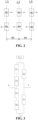
- FIG. 2 is a schematic diagram of the positions of magnetoresistors in a current measurement device provided by an embodiment of the present invention.
- the current measurement device provided by this embodiment includes N different positions, each position provided with at least two magnetoresistors, N being greater than or equal to 3.
- the two magnetoresistors at the same position include a magnetoresistor with a first sensing direction and a magnetoresistor with a second sensing direction, the first sensing direction and the second sensing direction are opposite, and the resistance value of the magnetoresistor has, within a set range, a linear relationship with the magnetic field at the position where the magnetoresistor is located.
- the sensing directions of all the magnetoresistors at the N different positions are the same or opposite, and the magnetic field to be measured has a component in the sensing direction of the magnetoresistor.
- the component, in the sensing direction, of the magnetic field to be measured in at least one position is different from the components, in the sensing direction, of the magnetic field to be measured at other positions.
- All the magnetoresistors are electrically connected to form a resistor network.
- An output signal of the resistor network includes the signal of the magnetic field to be measured and does not include or includes an interference magnetic field signal less than a first preset intensity.
- the interference magnetic field signal includes a uniform interference magnetic field and a gradient interference magnetic field.
- the current measurement device includes at least 3 different positions, each position provided with at least two magnetoresistors, N being greater than or equal to 3.
- the two magnetoresistors at the same position include a magnetoresistor with a first sensing direction and a magnetoresistor with a second sensing direction, the first sensing direction and the second sensing direction are opposite, and the resistance value of the magnetoresistor has, within a set range, a linear relationship with the magnetic field at the position where the magnetoresistor is located. It can be understood that the same position of the current measurement device means that the magnetic field generated by the current at that position is the same.
- the position L1 is provided with at least two magnetoresistors R1 and R2
- the position L2 is provided with at least two magnetoresistors R3 and R4
- the position L3 is provided with at least two magnetoresistors R5 and R5. That is, the magnetic field generated by the current at the position L1 is the same, the magnetic field generated by the current at the position L2 is the same, the magnetic field generated by the current at the position L3 is the same, and the magnetic fields generated by the current at different positions are different.
- the sensing directions of the magnetoresistors R1 and R2 located at the same position are opposite, the sensing directions of the magnetoresistors R3 and R4 located at the same position are opposite, and the sensing directions of the magnetoresistors R5 and R6 located at the same position are opposite.
- the physical locations and reference directions of the magnetoresistors in the current measurement device are shown in FIG. 2 .
- the spacing between adjacent positions are the same, then the spacing between L1 and L2 and the spacing between L2 and L3 are the same, and the spacings are both m.
- the sensing directions of all the magnetoresistors at the N different positions are the same or opposite.
- the sensing directions of the magnetoresistors R1, R3 and R5 at the three different positions are the same, and the sensing directions of the magnetoresistors R2, R4 and R6 at the three different positions are the same, but the sensing directions of all the magnetoresistors are parallel to the direction of arrangement of the physical positions of the magnetoresistors.
- the sensing directions of all the magnetoresistors and the directions of arrangement of the physical positions of the magnetoresistors may not be parallel, but rather intersect with each other.
- the magnetic field to be measured is generated after the current flows into the current measurement device.
- the magnetic field to be measured has a component in the sensing direction of each magnetoresistor. It is known that the magnetic field generated by the current at the same position is the same and the magnetic fields generated at different positions are different, then the component, in the sensing direction, of the magnetic field to be measured sensed in at least one position is different from the components, in the sensing directions, of the magnetic field to be measured at other positions.
- All the magnetoresistors in the current measurement device are electrically connected to form a resistor network.
- An output signal of the resistor network includes the signal of the magnetic field to be measured and does not include or includes an interference magnetic field signal less than a first preset intensity.
- the interference magnetic field signal includes a uniform interference magnetic field and a gradient interference magnetic field.
- the N different positions are distributed on the same straight line.
- the N different positions are distributed to be equally spaced.
- the process of eliminating or reducing the interference magnetic field by the current measurement device is explained with specific examples.
- the magnetoresistors at the N different positions in the current measurement device are electrically connected to form a half-bridge structure.
- the resistor network has a supply terminal Vcc, a ground terminal and an output terminal.
- the structure of the resistor network includes at least two half-bridge structures.
- the half-bridge structure is formed by an upper bridge arm and a lower bridge arm. One terminal of the upper bridge arm is electrically connected to the power supply terminal, one terminal of the lower bridge arm is electrically connected to the ground terminal, and the other terminal of the upper bridge arm and the other terminal of the lower bridge arm are both electrically connected to the output terminal.
- the magnetoresistor in the upper bridge arm includes magnetoresistors at one or more positions, and the magnetoresistors in the upper bridge arm have the same sensing direction
- the magnetoresistor in the lower bridge arm includes magnetoresistors at one or more positions, and the magnetoresistors in the lower bridge arm have the same sensing direction.
- the sensing direction of the magnetoresistors in the upper bridge arm is different from that of the magnetoresistors in the lower bridge arm.
- the form of electrical connection in which the magnetoresistors are electrically connected to form the half-bridge structure is a series electrical connection and/or a parallel electrical connection.
- the current measurement device further includes: a current wire that generates a magnetic field to be measured to reflect the magnitude and direction of the current in the current wire.
- the structure of the resistor network is used to enable the output signal of the resistor network to include the signal of the magnetic field to be measured and not include or include an interference magnetic field signal less than a first preset intensity, so that the current measurement device reflects the magnitude and direction of the current in the current wire without being influenced by the interference magnetic field.
- N is 3, and the N different positions are a first position L1, a second position L2 and a third position L3 in sequence.
- Some magnetoresistors at the first position L1 and the third position L3 are electrically connected to form an upper bridge arm of a first half-bridge structure.
- the other magnetoresistors at the first position L1 and the third position L3 are electrically connected to form a lower bridge arm of the first half-bridge structure.
- Some magnetoresistors at the second position L2 are electrically connected to form an upper bridge arm of a second half-bridge structure.
- the other magnetoresistors at the second position L2 are electrically connected to form a lower bridge arm of the second half-bridge structure.
- An output terminal signal of the first half-bridge structure and an output terminal signal of the second half-bridge structure are combined to reflect the magnitude and direction of the current in the current wire.
- FIG. 3 is a schematic diagram of an anti-interference bridge structure in a current measurement device provided by an embodiment of the present invention.
- the resistor network has a power supply terminal Vcc, a ground terminal and an output terminal (V+ and V-).
- Three magnetoresistor groups, i.e., six magnetoresistors, in the current measurement device are connected to form two half-bridge structures.
- R1 and R5 form the upper bridge arm of the first half-bridge structure
- R2 and R6 form the lower bridge arm of the first half-bridge structure
- R3 forms the upper bridge arm of the second half-bridge structure
- R4 forms the lower bridge arm of the second half-bridge structure.
- the sensing directions of the upper bridge arm of the first half-bridge structure and the upper bridge arm of the second half-bridge structure are the same, the sensing directions of the lower bridge arm of the first half-bridge structure and the lower bridge arm of the second half-bridge structure are the same, and the sensing directions of the upper bridge arm and the lower bridge arm are opposite.
- the interference field existing in the sensing direction can be considered as a combined field of the gradient interference magnetic field Hg (magnetic field changing per unit distance) and the uniform interference magnetic field Hu.
- Hg magnetic field changing per unit distance
- Hu uniform interference magnetic field
- n is the sensitivity of the magnetoresistors to the interference magnetic field.
- the current to be measured generates a magnetic field component in the sensing direction of the magnetoresistor.
- the resistance value of the magnetoresistor changes with the changes of the induced magnetic field and interference magnetic field of the current to be measured at the respective position of the magnetoresistor.
- a corresponding voltage signal is output through the half-bridge structure, from which the magnitude of the current can be calculated.
- the final output signal Vout of the current measurement device eliminates the interference from the gradient interference magnetic field Hg and the uniform interference magnetic field Hu.
- the output signal of the resistor network does not include interference magnetic field signal or only includes very little interference magnetic field signal.
- the first preset intensity is a preset minimum intensity value, just to indicate that the output signal of the resistor network does not include or includes very little interference magnetic field signal.
- the interference magnetic field signal includes a uniform interference magnetic field and a gradient interference magnetic field.
- the sensing directions of corresponding positions in the first and second half-bridge structures are not necessarily the same.
- the final output signal Vout of the current measurement device still eliminates the interference from the gradient interference magnetic field Hg and the uniform interference magnetic field Hu.
- the distances between the three physical positions may be slightly different and are not limited to being equal in spacing. Those skilled in the art can reasonably design the spacing between the three physical positions, provided that the interference magnetic field can be eliminated.
- the current measurement device includes N different positions, each position provided with at least two magnetoresistors, N being greater than or equal to 3.
- the two magnetoresistors at the same position include a magnetoresistor with a first sensing direction and a magnetoresistor with a second sensing direction, the first sensing direction and the second sensing direction are opposite, and the resistance value of the magnetoresistor has, within a set range, a linear relationship with the magnetic field at the position where the magnetoresistor is located.
- the sensing directions of all the magnetoresistors at the N different positions are the same or opposite, and the magnetic field to be measured has a component in the sensing direction of the magnetoresistor.
- the component, in the sensing direction, of the magnetic field to be measured in at least one position is different from the components, in the sensing direction, of the magnetic field to be measured at other positions.
- All the magnetoresistors are electrically connected to form a resistor network.
- An output signal of the resistor network includes the signal of the magnetic field to be measured and does not include or includes an interference magnetic field signal less than a first preset intensity.
- the interference magnetic field signal includes a uniform interference magnetic field and a gradient interference magnetic field.
- the signal output by the current measurement device includes no or very little interference magnetic field signal, which effectively eliminates or reduces the interference of the interference magnetic field with current measurement, and achieves accurate detection of the current.
- N is 3, and the N different positions are a first position, a second position and a third position in sequence.
- Some magnetoresistors at the first position are electrically connected to form an upper bridge arm of a first half-bridge structure.
- the other magnetoresistors at the first position are electrically connected to form a lower bridge arm of the first half-bridge structure.
- Some magnetoresistors at the second position are electrically connected to form an upper bridge arm of a second half-bridge structure.
- the other magnetoresistors at the second position are electrically connected to form a lower bridge arm of the second half-bridge structure.
- Some magnetoresistors at the third position are electrically connected to form an upper bridge arm of the third half-bridge structure.
- the other magnetoresistors at the third position are electrically connected to form a lower bridge arm of the third half-bridge structure.
- An output terminal signal of the first half-bridge structure, an output terminal signal of the second half-bridge structure and an output terminal signal of the third half-bridge structure are combined to reflect the magnitude and direction of the current in the current wire.
- FIG. 4 is a schematic diagram of an anti-interference bridge structure in another current measurement device provided by an embodiment of the present invention.
- the resistor network has a power supply terminal Vcc, a ground terminal and an output terminal (V1, V2 and V3).
- the positions of the six magnetoresistors are the same as in FIG. 2 , but the resistor network is formed by three half-bridge structures.
- R1 and R2 form the upper and lower bridge arms of the first half-bridge structure respectively
- R3 and R4 form the upper and lower bridge arms of the second half-bridge structure respectively
- R5 and R6 form the upper and lower bridge arms of the third half-bridge structure respectively.
- the output signal of the first half-bridge structure is V1
- the output signal of the second half-bridge structure is V2
- the output signal of the third half-bridge structure is V3.
- the final output signal Vout of the current measurement device still eliminates the interference from the gradient interference magnetic field Hg and the uniform interference magnetic field Hu.
- FIG. 5 is a schematic diagram of an anti-interference bridge structure in yet another current measurement device provided by an embodiment of the present invention.
- FIG. 5 is a variation of the three half-bridge structures in FIG. 4 , in which the resistor network has a power supply terminal Vcc, a ground terminal and an output terminal (V1, V2, V3 and V4).
- the resistor network uses the connection pattern of the four half-bridge structures shown in FIG. 5 , which is beneficial to connecting the bridge to the subsequent operational amplifier (“OP-AMP") circuit.
- OP-AMP operational amplifier
- the final output signal Vout of the current measurement device eliminates the interference from the gradient interference magnetic field Hg and the uniform interference magnetic field Hu.
- N is 4, and the N different positions are a first position, second position, third position and fourth position in sequence.
- the magnetoresistors at the first position and the fourth position are electrically connected to form an upper bridge arm of a first half-bridge structure.
- the magnetoresistors at the first position and the fourth position are electrically connected to form a lower bridge arm of the first half-bridge structure.
- the magnetoresistors at the second position and the third position are electrically connected to form an upper bridge arm of a second half-bridge structure.
- the magnetoresistors at the second position and the third position are electrically connected to form a lower bridge arm of the second half-bridge structure.
- An output terminal signal of the first half-bridge structure and an output terminal signal of the second half-bridge structure are combined to reflect the magnitude and direction of the current in the current wire.
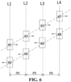
- FIG. 6 is a schematic diagram of the positions of the magnetoresistors in yet another current measurement device provided by an embodiment of the present invention.
- the four different positions of the current measurement device can be denoted as L1, L2, L3 and L4 in sequence.
- the position L1 is provided with at least two magnetoresistors R1 and R2
- the position L2 is provided with at least two magnetoresistors R3 and R4
- the position L3 is provided with at least two magnetoresistors R5 and R6
- the position L4 is provided with at least two magnetoresistors R7 and R8.
- the magnetic field generated by the current at the position L1 is the same
- the magnetic field generated by the current at the position L2 is the same
- the magnetic field generated by the current at the position L3 is the same
- the magnetic field generated by the current at the position L4 is the same
- the magnetic fields generated by the current at different positions are different.
- the sensing directions of the magnetoresistors R1 and R2 located at the same position are opposite, the sensing directions of the magnetoresistors R3 and R4 are opposite, the sensing directions of the magnetoresistors R5 and R6 are opposite, and the sensing directions of the magnetoresistors R7 and R8 are opposite.
- the physical positions and reference directions of the magnetoresistors in the current measurement device are shown in FIG. 6 .
- the sensing directions of the magnetoresistor R1, R3, R5 and R7 are the same, the sensing directions of the magnetoresistor R2, R4, R6 and R8 are the same, and the sensing directions of R1 and R2 are opposite. It can be understood that the sensing directions of the magnetoresistors intersect with the arrangement direction of the positions of the magnetoresistors.
- the spacings between the positions L1 and L2, the positions L2 and L3, and the positions L3 and L4 are the same. For example, they are all m.
- the resistor network formed by eight magnetoresistors has two half-bridge structures.
- FIG. 7 is a schematic diagram of an anti-interference bridge structure in yet another current measurement device provided by an embodiment of the present invention.
- the resistor network has a power supply terminal Vcc, a ground terminal and an output terminal (V+ and V-).
- Vcc power supply terminal
- R2 and R8 form a lower bridge arm of the first half-bridge structure
- R3 and R5 form an upper bridge arm of the second half-bridge structure
- R4 and R6 form a lower bridge arm of the second half-bridge structure.
- the output signal of the first half-bridge structure is V+
- the output signal of the second half-bridge structure is V-.
- the final output signal Vout of the current measurement device eliminates the interference from the gradient interference magnetic field Hg and the uniform interference magnetic field Hu.
- N is an odd number greater than or equal to 5.
- R 1 R 0 ⁇ aI ⁇ nHu
- R 2 R 0 + aI + nHu
- R 3 R 0 ⁇ bI ⁇ n Hu + Hg
- R 4 R 0 + bI + n Hu + Hg
- R 6 R 0 + cI + n Hu + 2 Hg ⁇ Position N : R 2 N ⁇ 1 , R 2 N .
- R1,..., R(4N+1) form an upper bridge arm of a first half-bridge structure
- R2,..., R(4N+2) form a lower bridge arm of the first half-bridge structure
- R3,..., R(4N-1) form an upper bridge arm of a second half-bridge structure
- R4, ..., R(4N) form a lower bridge arm of the second half-bridge structure.
- the differential output signal of the two half-bridge structures is a signal that eliminates the interference from the gradient interference magnetic field Hg and the uniform interference magnetic field Hu.
- R1, R5, R9 and R13 form an upper bridge arm of the first half-bridge structure
- R2, R6, R10 and R14 form a lower bridge arm of the first half-bridge structure
- R3, R7 and R11 form an upper bridge arm of a second half-bridge structure
- R4, R8 and R12 form a lower bridge arm of the second half-bridge structure.
- the final output signal Vout of the current measurement device eliminates the interference from the gradient interference magnetic field Hg and the uniform interference magnetic field Hu.
- N is an even number greater than or equal to 5.
- each position is provided with two magnetoresistors.
- the magnetoresistors R1-R12 at the six positions can form a half-bridge structure of different solutions.
- R1, R3, R9 and R11 are the upper bridge arm of the first half-bridge structure
- R2, R4, R10 and R12 are the lower bridge arm of the first half-bridge structure
- R5 and R7 are the upper bridge arm of the second half-bridge structure
- R6 and R8 are the lower bridge arm of the second half-bridge structure.
- a first-order differential operation is made on V+ and V- to obtain the final output signal Vout, which eliminates the interference from the gradient interference magnetic field Hg and the uniform interference magnetic field Hu.
- R1 and R11 are the upper bridge arm of the first half-bridge structure
- R2 and R12 are the lower bridge arm of the first half-bridge structure
- R3, R5, R7 and R9 are the upper bridge arm of the second half-bridge structure
- R4, R6, R8 and R10 are the lower bridge arm of the second half-bridge structure.
- a first-order differential operation is made on V+ and V- to obtain the final output signal Vout, which eliminates the interference from the gradient interference magnetic field Hg and the uniform interference magnetic field Hu.
- the magnetoresistors R1-R16 at the eight positions can form two half-bridge structures.
- R1, R3, R13 and R15 are the upper bridge arm of the first half-bridge structure
- R2, R4, R14, R16 are the lower bridge arm of the first half-bridge structure
- R5, R7, R9 and R11 are the upper bridge arm of the second half-bridge structure
- R6, R8, R10 and R12 are the lower bridge arm of the second half-bridge structure.
- an anti-interference bridge structure is provided without introducing other components, and the magnetoresistor output eliminates the influence of both the gradient interference magnetic field and the uniform interference magnetic field, improving the detection accuracy and being suitable for a variety of application scenarios.
- the sensing direction of the magnetoresistor may be any direction, provided that the magnetic field induced by the current to be measured has a magnetic field component in the selected sensing direction of the magnetoresistor.
Landscapes
- Physics & Mathematics (AREA)
- General Physics & Mathematics (AREA)
- Measuring Instrument Details And Bridges, And Automatic Balancing Devices (AREA)
- Measuring Magnetic Variables (AREA)
Applications Claiming Priority (2)
| Application Number | Priority Date | Filing Date | Title |
|---|---|---|---|
| CN202111172335.8A CN113917216B (zh) | 2021-10-08 | 2021-10-08 | 一种电流测量器件 |
| PCT/CN2022/118642 WO2023056827A1 (zh) | 2021-10-08 | 2022-09-14 | 一种电流测量器件 |
Publications (2)
| Publication Number | Publication Date |
|---|---|
| EP4414718A1 true EP4414718A1 (de) | 2024-08-14 |
| EP4414718A4 EP4414718A4 (de) | 2025-10-15 |
Family
ID=79238402
Family Applications (1)
| Application Number | Title | Priority Date | Filing Date |
|---|---|---|---|
| EP22877847.8A Pending EP4414718A4 (de) | 2021-10-08 | 2022-09-14 | Strommessvorrichtung |
Country Status (5)
| Country | Link |
|---|---|
| US (1) | US20240402221A1 (de) |
| EP (1) | EP4414718A4 (de) |
| JP (1) | JP2024533845A (de) |
| CN (1) | CN113917216B (de) |
| WO (1) | WO2023056827A1 (de) |
Families Citing this family (5)
| Publication number | Priority date | Publication date | Assignee | Title |
|---|---|---|---|---|
| CN113917216B (zh) * | 2021-10-08 | 2024-10-29 | 江苏多维科技有限公司 | 一种电流测量器件 |
| CN117572303B (zh) * | 2022-08-08 | 2024-09-17 | 苏州纳芯微电子股份有限公司 | 一种磁传感器、电流检测装置及电流检测方法 |
| CN116482432B (zh) * | 2023-03-13 | 2024-12-13 | 安徽希磁科技股份有限公司 | 电流传感器、电流检测电路及电源设备 |
| CN116087588B (zh) * | 2023-04-11 | 2023-10-13 | 江苏多维科技有限公司 | 一种抗外场干扰的电流传感器 |
| CN117405958B (zh) * | 2023-12-14 | 2024-02-13 | 江苏多维科技有限公司 | 电流传感器 |
Family Cites Families (23)
| Publication number | Priority date | Publication date | Assignee | Title |
|---|---|---|---|---|
| JP2000516724A (ja) * | 1997-06-13 | 2000-12-12 | コーニンクレッカ フィリップス エレクトロニクス エヌ ヴィ | ホイートストンブリッジを有するセンサ |
| CN1274086A (zh) * | 1999-12-21 | 2000-11-22 | 南京大学 | 巨磁电阻效应交、直流两用电流检测、控制器件 |
| JP5295163B2 (ja) * | 2010-04-01 | 2013-09-18 | 三菱電機株式会社 | 磁界検出装置およびそれを調整する方法 |
| EP2648006A4 (de) * | 2010-12-02 | 2017-11-29 | Alps Electric Co., Ltd. | Stromsensor |
| CN102129053B (zh) * | 2011-01-20 | 2012-10-10 | 清华大学 | 一种基于巨磁电阻效应的测量磁场方向和强度的传感器 |
| CN105143902B (zh) * | 2013-03-18 | 2018-01-23 | 日立金属株式会社 | 磁传感器 |
| CN103645369B (zh) * | 2013-11-15 | 2017-03-01 | 无锡乐尔科技有限公司 | 一种电流传感装置 |
| JP2015219058A (ja) * | 2014-05-15 | 2015-12-07 | 旭化成エレクトロニクス株式会社 | 電流センサ |
| CN104900801A (zh) * | 2015-04-23 | 2015-09-09 | 美新半导体(无锡)有限公司 | 一种反铁磁钉扎各向异性磁电阻(amr)传感器 |
| CN107615079B (zh) * | 2015-07-01 | 2019-11-12 | 株式会社村田制作所 | 电流传感器 |
| JP6522485B2 (ja) * | 2015-11-19 | 2019-05-29 | アルプスアルパイン株式会社 | 磁気センサの製造方法 |
| CN105353192A (zh) * | 2015-11-19 | 2016-02-24 | 无锡乐尔科技有限公司 | 一种电流传感器 |
| CN109313223B (zh) | 2016-06-15 | 2021-02-26 | 株式会社电装 | 电流传感器 |
| CN206311652U (zh) * | 2016-08-05 | 2017-07-07 | 江苏多维科技有限公司 | 一种具有集成电流线圈的磁电阻电流传感器 |
| KR101965510B1 (ko) * | 2017-11-16 | 2019-08-07 | 재단법인대구경북과학기술원 | 거대자기저항 센서 |
| CN108469594B (zh) * | 2018-03-13 | 2023-07-07 | 武汉嘉晨电子技术有限公司 | 一种高精度、闭环式梯度磁阻传感器 |
| CN108398588B (zh) * | 2018-04-27 | 2024-12-27 | 宁波希磁电子科技有限公司 | 一种电流传感器 |
| CN110857952B (zh) * | 2018-08-22 | 2022-03-08 | 爱盛科技股份有限公司 | 电流传感器 |
| JP2020095029A (ja) | 2018-12-12 | 2020-06-18 | メレキシス テクノロジーズ エス エーMelexis Technologies SA | 電流センサ |
| JP7024811B2 (ja) * | 2019-12-11 | 2022-02-24 | Tdk株式会社 | 磁場検出装置および電流検出装置 |
| CN214335046U (zh) * | 2020-10-30 | 2021-10-01 | 中光华研电子科技有限公司 | 一种基于amr传感器阵列的小电流测量装置 |
| CN113917216B (zh) * | 2021-10-08 | 2024-10-29 | 江苏多维科技有限公司 | 一种电流测量器件 |
| CN113945873A (zh) * | 2021-10-18 | 2022-01-18 | 江苏多维科技有限公司 | 一种磁传感器装置 |
-
2021
- 2021-10-08 CN CN202111172335.8A patent/CN113917216B/zh active Active
-
2022
- 2022-09-14 WO PCT/CN2022/118642 patent/WO2023056827A1/zh not_active Ceased
- 2022-09-14 JP JP2024520885A patent/JP2024533845A/ja active Pending
- 2022-09-14 US US18/699,497 patent/US20240402221A1/en active Pending
- 2022-09-14 EP EP22877847.8A patent/EP4414718A4/de active Pending
Also Published As
| Publication number | Publication date |
|---|---|
| WO2023056827A1 (zh) | 2023-04-13 |
| US20240402221A1 (en) | 2024-12-05 |
| CN113917216B (zh) | 2024-10-29 |
| JP2024533845A (ja) | 2024-09-12 |
| CN113917216A (zh) | 2022-01-11 |
| EP4414718A4 (de) | 2025-10-15 |
Similar Documents
| Publication | Publication Date | Title |
|---|---|---|
| EP4414718A1 (de) | Strommessvorrichtung | |
| EP4421511A1 (de) | Magnetsensorvorrichtung | |
| CN106443063B (zh) | 旋转检测装置 | |
| CN105222812B (zh) | 具有三个半桥结构的传感器系统 | |
| US20250067780A1 (en) | Current sensor | |
| US20030222642A1 (en) | Arrangement for determining the position of a motion sensor element | |
| CN110494760A (zh) | 磁传感器 | |
| CN103328986A (zh) | 电流传感器 | |
| CN110609072B (zh) | 一种普鲁士蓝膜生物电极的微弱信号检测电路 | |
| CN106908845A (zh) | 电磁法勘查的一次场弱耦合接收装置及方法 | |
| CN101846487A (zh) | 一种磁阵列位置传感装置及其定位方法 | |
| CN115265605B (zh) | 传感器电路及运动数据检测装置 | |
| CN113820386B (zh) | 钢丝帘布缺陷检测装置 | |
| CN118425594A (zh) | 非接触式高精度环形tmr阵列电流传感器 | |
| CN118362771A (zh) | 一种椭圆形阵列霍尔电流传感器及电流高精度检测方法 | |
| WO2019205775A1 (zh) | 一种电流传感器 | |
| CN113049868B (zh) | 一种交直流电流测量装置及测量方法 | |
| CN109613322A (zh) | 铜排型导线的电流测量方法及装置 | |
| CN209624669U (zh) | 铜排型导线的电流测量装置 | |
| CN215894477U (zh) | 钢丝帘布缺陷检测装置 | |
| CN203981183U (zh) | 一种齿轮传感器 | |
| CN209372934U (zh) | 磁通门电流传感器的多闭环控制电路 | |
| JP2016142652A (ja) | 電力センサー | |
| Bazzocchi et al. | Spatial DFT analysis from magnetic sensor circular array data for measuring a DC current flowing in a rectangular bus-bar | |
| CN112964928B (zh) | 无集磁铁芯的钳形电流表及自动平衡调整方法 |
Legal Events
| Date | Code | Title | Description |
|---|---|---|---|
| STAA | Information on the status of an ep patent application or granted ep patent |
Free format text: STATUS: THE INTERNATIONAL PUBLICATION HAS BEEN MADE |
|
| PUAI | Public reference made under article 153(3) epc to a published international application that has entered the european phase |
Free format text: ORIGINAL CODE: 0009012 |
|
| STAA | Information on the status of an ep patent application or granted ep patent |
Free format text: STATUS: REQUEST FOR EXAMINATION WAS MADE |
|
| 17P | Request for examination filed |
Effective date: 20240418 |
|
| AK | Designated contracting states |
Kind code of ref document: A1 Designated state(s): AL AT BE BG CH CY CZ DE DK EE ES FI FR GB GR HR HU IE IS IT LI LT LU LV MC MK MT NL NO PL PT RO RS SE SI SK SM TR |
|
| DAV | Request for validation of the european patent (deleted) | ||
| DAX | Request for extension of the european patent (deleted) | ||
| REG | Reference to a national code |
Ref country code: DE Ref legal event code: R079 Free format text: PREVIOUS MAIN CLASS: G01R0019000000 Ipc: G01R0015200000 |
|
| A4 | Supplementary search report drawn up and despatched |
Effective date: 20250917 |
|
| RIC1 | Information provided on ipc code assigned before grant |
Ipc: G01R 15/20 20060101AFI20250911BHEP Ipc: G01R 17/10 20060101ALI20250911BHEP |