EP4414564A2 - Magnetventilsteuervorrichtung - Google Patents
Magnetventilsteuervorrichtung Download PDFInfo
- Publication number
- EP4414564A2 EP4414564A2 EP24182591.8A EP24182591A EP4414564A2 EP 4414564 A2 EP4414564 A2 EP 4414564A2 EP 24182591 A EP24182591 A EP 24182591A EP 4414564 A2 EP4414564 A2 EP 4414564A2
- Authority
- EP
- European Patent Office
- Prior art keywords
- terminal
- solenoid valve
- connector
- block
- electrical power
- Prior art date
- Legal status (The legal status is an assumption and is not a legal conclusion. Google has not performed a legal analysis and makes no representation as to the accuracy of the status listed.)
- Granted
Links
Images

Classifications
-
- F—MECHANICAL ENGINEERING; LIGHTING; HEATING; WEAPONS; BLASTING
- F15—FLUID-PRESSURE ACTUATORS; HYDRAULICS OR PNEUMATICS IN GENERAL
- F15B—SYSTEMS ACTING BY MEANS OF FLUIDS IN GENERAL; FLUID-PRESSURE ACTUATORS, e.g. SERVOMOTORS; DETAILS OF FLUID-PRESSURE SYSTEMS, NOT OTHERWISE PROVIDED FOR
- F15B13/00—Details of servomotor systems ; Valves for servomotor systems
- F15B13/02—Fluid distribution or supply devices characterised by their adaptation to the control of servomotors
- F15B13/06—Fluid distribution or supply devices characterised by their adaptation to the control of servomotors for use with two or more servomotors
- F15B13/08—Assemblies of units, each for the control of a single servomotor only
- F15B13/0803—Modular units
- F15B13/0846—Electrical details
- F15B13/0853—Electric circuit boards
-
- F—MECHANICAL ENGINEERING; LIGHTING; HEATING; WEAPONS; BLASTING
- F15—FLUID-PRESSURE ACTUATORS; HYDRAULICS OR PNEUMATICS IN GENERAL
- F15B—SYSTEMS ACTING BY MEANS OF FLUIDS IN GENERAL; FLUID-PRESSURE ACTUATORS, e.g. SERVOMOTORS; DETAILS OF FLUID-PRESSURE SYSTEMS, NOT OTHERWISE PROVIDED FOR
- F15B13/00—Details of servomotor systems ; Valves for servomotor systems
- F15B13/02—Fluid distribution or supply devices characterised by their adaptation to the control of servomotors
- F15B13/04—Fluid distribution or supply devices characterised by their adaptation to the control of servomotors for use with a single servomotor
- F15B13/044—Fluid distribution or supply devices characterised by their adaptation to the control of servomotors for use with a single servomotor operated by electrically-controlled means, e.g. solenoids, torque-motors
-
- F—MECHANICAL ENGINEERING; LIGHTING; HEATING; WEAPONS; BLASTING
- F15—FLUID-PRESSURE ACTUATORS; HYDRAULICS OR PNEUMATICS IN GENERAL
- F15B—SYSTEMS ACTING BY MEANS OF FLUIDS IN GENERAL; FLUID-PRESSURE ACTUATORS, e.g. SERVOMOTORS; DETAILS OF FLUID-PRESSURE SYSTEMS, NOT OTHERWISE PROVIDED FOR
- F15B13/00—Details of servomotor systems ; Valves for servomotor systems
- F15B13/02—Fluid distribution or supply devices characterised by their adaptation to the control of servomotors
- F15B13/06—Fluid distribution or supply devices characterised by their adaptation to the control of servomotors for use with two or more servomotors
- F15B13/08—Assemblies of units, each for the control of a single servomotor only
- F15B13/0803—Modular units
- F15B13/0807—Manifolds
- F15B13/0817—Multiblock manifolds
-
- F—MECHANICAL ENGINEERING; LIGHTING; HEATING; WEAPONS; BLASTING
- F15—FLUID-PRESSURE ACTUATORS; HYDRAULICS OR PNEUMATICS IN GENERAL
- F15B—SYSTEMS ACTING BY MEANS OF FLUIDS IN GENERAL; FLUID-PRESSURE ACTUATORS, e.g. SERVOMOTORS; DETAILS OF FLUID-PRESSURE SYSTEMS, NOT OTHERWISE PROVIDED FOR
- F15B13/00—Details of servomotor systems ; Valves for servomotor systems
- F15B13/02—Fluid distribution or supply devices characterised by their adaptation to the control of servomotors
- F15B13/06—Fluid distribution or supply devices characterised by their adaptation to the control of servomotors for use with two or more servomotors
- F15B13/08—Assemblies of units, each for the control of a single servomotor only
- F15B13/0803—Modular units
- F15B13/0832—Modular valves
- F15B13/0839—Stacked plate type valves
-
- F—MECHANICAL ENGINEERING; LIGHTING; HEATING; WEAPONS; BLASTING
- F15—FLUID-PRESSURE ACTUATORS; HYDRAULICS OR PNEUMATICS IN GENERAL
- F15B—SYSTEMS ACTING BY MEANS OF FLUIDS IN GENERAL; FLUID-PRESSURE ACTUATORS, e.g. SERVOMOTORS; DETAILS OF FLUID-PRESSURE SYSTEMS, NOT OTHERWISE PROVIDED FOR
- F15B13/00—Details of servomotor systems ; Valves for servomotor systems
- F15B13/02—Fluid distribution or supply devices characterised by their adaptation to the control of servomotors
- F15B13/06—Fluid distribution or supply devices characterised by their adaptation to the control of servomotors for use with two or more servomotors
- F15B13/08—Assemblies of units, each for the control of a single servomotor only
- F15B13/0803—Modular units
- F15B13/0846—Electrical details
- F15B13/086—Sensing means, e.g. pressure sensors
Definitions
- the present invention relates to a solenoid valve control device configured to control solenoid valves.
- JP 2,511,402 Y2 discloses a solenoid valve manifold.
- the solenoid valve manifold includes a plurality of manifold blocks, and a plurality of solenoid valve mechanisms. Each of the manifold blocks includes a flow path through which air flows.
- the solenoid valve mechanisms are attached to each of the manifold blocks.
- the solenoid valve mechanisms include solenoid valves that switch the flow path of the air flowing through the manifold blocks.
- US 2006/0011240 A1 discloses a device according to the preamble of claim 1 and in particular a fluid power controller device comprising a plurality of valve modules arranged sequentially in a row direction and collected together as an array-like unit, such modules comprising respectively a principal valve having at least one moving valve member and at least one electrically operated valve drive for the principal valve. At least two of the valve modules placed sequentially in the row direction are spaced from each other with the formation of an intermediate space. In such intermediate space a diagnostic module is placed for the detection of at least one operational state of one or both principal valves.
- US 2019/245294 A1 discloses a series module for a modular designed control arrangement includes a first series interface and a first bus interface and a second series interface and a second bus interface, wherein a bus communication line is formed between the two bus interfaces and multiple connecting lines are formed between the two series interfaces and wherein the connecting lines are arranged at least partially Z-linked between the two series interfaces.
- DE 10 2005 055 261 A1 discloses a valve arrangement with a valve, in which at least one sensor and a signal transmitter connected thereto is arranged for wireless sensor signal transmission.
- a signal receiver for receiving the sensor signals from the signal transmitter is arranged on or in a connection device that can be mechanically connected to the valve.
- An electrical line arrangement in the connection device is used to forward the sensor signals received in the signal receiver.
- the wireless transmission of the sensor signals eliminates the contact problems that otherwise occur with conventional plug connections for sensor signal transmission due to the very low sensor currents or sensor voltages.
- US 2004/0003850 A1 discloses a manifold valve in which a sensor chamber is formed in an upper face of a casing of a solenoid valve, pressure sensors are disposed in the sensor chamber, a wiring block including a wiring path in itself is connected to a portion of the casing, and signal conductors extending from the pressure sensors are introduced into a wiring path in the wiring block and are connected to a main wiring substrate through an intermediate block.
- US 9,241,416 B2 discloses a module arrangement including a plurality of functional modules lined up in a stacking direction, which are connected to one another for fluidic and electric communication, wherein a functional module includes a plate-shaped base body having two parallel, opposite joining surfaces which are designed to contact joining surfaces of adjacent base bodies, wherein the base body includes a connecting device designed for transferring electric signals and/or electric supply voltages and/or fluid flows between adjacent functional modules along the stacking direction, and wherein several signal lines selectable by the control module extend along the stacking direction of the functional modules for transmitting control signals provided for the direct selection of individual functional modules wherein at least one storage device for detecting, buffering and transferring at least one electric signal of an external component is electrically looped into at least one signal line.
- US 2008/0115844 A1 discloses a mechatronic device comprising a housing that encompasses a mechanical part and an electronic part is provided.
- the mechanical part includes one or more solenoid valves and pressure-directing ducts.
- the electronic part includes a printed circuit board with electronic components.
- Sensor modules are incorporated in the pressure-directing ducts to measure physical parameters.
- the sensor modules wirelessly communicate with at least one reading station located on the circuit board by means of radio technology or light-emitting and light sensitive elements.
- CN 110971219 A discloses a switching circuit of a pressure sensor, which comprises an initial signal detection module used for detecting an initial signal sent by an external chip through a bus; an end signal detection module which is used for detecting an end signal sent by an external chip through a bus; a clock switch signal generation module which is used for generating a clock starting signal when the starting signal detection module detects a starting signal so as to control the pressure sensor to start a clock pulse; and when the end signal detection module detects an end signal, a clock closing signal is generated to control the pressure sensor to close the clock pulse.
- the invention also discloses the pressure sensor and a clock control method and a clock control device thereof. The power consumption of the pressure sensor is saved.
- pressure sensors are provided in order to detect the pressure of the air supplied to a pneumatic cylinder from each of the manifold blocks.
- Data lines for delivering pressure information detected by the pressure sensors to a PLC (Programmable Logic Controller) or the like are arranged externally of the solenoid valve manifold. Therefore, a problem arises in that the configuration of the wiring becomes complicated.
- the present invention has the object of solving the aforementioned problem.
- the data lines are wired internally of the solenoid valve control device, the number of the data lines arranged externally of the solenoid valve control device can be reduced. As a result, the wiring configuration can be simplified.
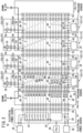
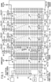
- FIG. 1 is a schematic diagram of a valve manifold 10.
- the valve manifold 10 according to the present embodiment is used in an air cylinder system and a vacuum ejector system.
- the air cylinder system is a system that delivers to a pneumatic device the compressed air supplied from an air pump connected to the valve manifold 10, and thereby causes the pneumatic device to be operated.
- the pneumatic device for example, is an air cylinder, an air chuck, or the like.
- the vacuum ejector system is a system that causes a negative pressure to be generated by compressed air that is supplied from an air pump connected to the valve manifold 10, and draws in air from a pneumatic device that is connected to the valve manifold 10.
- the pneumatic device for example, is a suction pad or the like.
- valve manifold 10 a plurality of solenoid valve modules 12 and a plurality of air supply and exhaust blocks 14 can be connected to each other.
- a control module 16 is connected with respect to the connected plurality of solenoid valve modules 12, and the plurality of air supply and exhaust blocks 14.
- the valve manifold 10 includes, as the solenoid valve modules 12, a first solenoid valve module 12a, a second solenoid valve module 12b, a third solenoid valve module 12c, and a fourth solenoid valve module 12d.
- the valve manifold 10 according to the present embodiment includes, as the air supply and exhaust blocks 14, an intermediate air supply and exhaust block 14a, and a terminal air supply and exhaust block 14b.
- control module 16 the intermediate air supply and exhaust block 14a, the first solenoid valve module 12a, the second solenoid valve module 12b, the third solenoid valve module 12c, the fourth solenoid valve module 12d, and the terminal air supply and exhaust block 14b are connected sequentially in this order.
- the mode of connection of the present embodiment illustrated in FIG. 1 is shown as an example, and the order in which each of the solenoid valve modules 12 and each of the air supply and exhaust blocks 14 are connected is selected by the user. Further, the number of the solenoid valve modules 12 and the number of the air supply and exhaust blocks 14 in the valve manifold 10 are selected by the user.
- Each of the intermediate air supply and exhaust block 14a, the first solenoid valve module 12a, the second solenoid valve module 12b, the third solenoid valve module 12c, the fourth solenoid valve module 12d, and the terminal air supply and exhaust block 14b includes a first connector 18.
- Each of the first connectors 18 has terminals A0 to A15.
- Each of the control module 16, the intermediate air supply and exhaust block 14a, the first solenoid valve module 12a, the second solenoid valve module 12b, the third solenoid valve module 12c, and the fourth solenoid valve module 12d includes a second connector 20.
- Each of the second connectors 20 has terminals B0 to B15.
- the control module 16 By the first connectors 18 and the second connectors 20 being connected, the control module 16, the intermediate air supply and exhaust block 14a, the first solenoid valve module 12a, the second solenoid valve module 12b, the third solenoid valve module 12c, the fourth solenoid valve module 12d, and the terminal air supply and exhaust block 14b are connected.
- the terminal A9 of each of the first connectors 18 corresponds to the first terminal of the present invention.
- the terminal A10 of each of the first connectors 18 corresponds to the second terminal of the present invention.
- the terminal B9 each of the second connectors 20 corresponds to the third terminal of the present invention.
- the control module 16 includes an output driver 22, a control circuit 24, and an internal electrical power source 26.
- the output driver 22 outputs control signals. Based on the control signals, solenoid valves 28 respectively provided in the solenoid valve modules 12 and the terminal air supply and exhaust block 14b are driven.
- the output driver 22 includes semiconductor switches that are provided corresponding to the respective solenoid valves 28. By turning on the semiconductor switches, electrical power is supplied from a driving electrical power source 30 to coils 32 of the solenoid valves 28.
- the control circuit 24 serves to control the output driver 22.
- the control circuit 24 carries out communication with pressure sensors 34 provided in the first solenoid valve module 12a, the second solenoid valve module 12b, and the terminal air supply and exhaust block 14b.
- Each of the pressure sensors 34 is equipped with an amplifier circuit, an AD conversion circuit, a communication circuit, and the like. Therefore, the pressure sensors 34 are each capable of carrying out communication individually with the control circuit 24.
- the control circuit 24 communicates with a PLC 36 and other devices. The other devices, for example, are other valve manifolds 10 or the like.
- the internal electrical power source 26 supplies electrical power to the control circuit 24 and the pressure sensors 34.
- the control module 16 includes an electrical power interface (not shown), and a communication interface (not shown).
- the electrical power interface adjusts the voltage of the electrical power supplied from the driving electrical power source 30, and delivers the adjusted electrical power to the output driver 22 and the solenoid valves 28.
- the electrical power interface adjusts the voltage of the electrical power supplied from a controlling electrical power source 38, and delivers the adjusted electrical power to the control circuit 24 and the pressure sensors 34.
- the terminal B0 is connected to a positive electrode of the driving electrical power source 30.
- the terminals B1 to B8 are connected to respective switches of the output driver 22.
- the terminals B9 to B13 are connected to the control circuit 24.
- the terminal B14 is connected to a positive electrode of the internal electrical power source 26.
- the terminal B15 is connected to a negative electrode of the internal electrical power source 26.
- Compressed air is supplied from the exterior to the intermediate air supply and exhaust block 14a.
- the compressed air supplied to the intermediate air supply and exhaust block 14a is delivered to the first solenoid valve module 12a and the second solenoid valve module 12b.
- a common electrical power source line 40 is provided in the intermediate air supply and exhaust block 14a.
- the common electrical power source line 40 is electrically connected between the terminal A0 of the first connector 18 and the terminal B0 of the second connector 20.
- the common electrical power source line 40 is connected to the positive electrode of the driving electrical power source 30 via the control module 16.
- a plurality of control lines 42 are provided in the intermediate air supply and exhaust block 14a.
- One of the control lines 42 is electrically connected between the terminal A1 of the first connector 18 and the terminal B1 of the second connector 20.
- the other control lines 42 are electrically connected between the terminal A2 and the terminal B2, between the terminal A3 and the terminal B3, between the terminal A4 and the terminal B4, between the terminal A5 and the terminal B5, between the terminal A6 and the terminal B6, between the terminal A7 and the terminal B7, and between the terminal A8 and the terminal B8.
- the control lines 42 are connected to the negative electrode of the driving electrical power source 30 via the control module 16.
- a plurality of data lines 44 are provided in the intermediate air supply and exhaust block 14a.
- the data lines 44 are signal lines that deliver the pressure information detected by each of the pressure sensors 34 to the control circuit 24 of the control module 16.
- One of the data lines 44 is electrically connected between the terminal A9 of the first connector 18 and the terminal B9 of the second connector 20.
- the other data lines 44 are electrically connected between the terminal A10 and the terminal B10, between the terminal A11 and the terminal B11, and between the terminal A12 and the terminal B12.
- a clock line 46 is provided in the intermediate air supply and exhaust block 14a.
- the clock line 46 is a signal line that delivers a clock signal from the control circuit 24 of the control module 16 to each of the pressure sensors 34.
- the clock line 46 is electrically connected between the terminal A13 of the first connector 18 and the terminal B13 of the second connector 20.
- Two internal electrical power source lines 48 are provided in the intermediate air supply and exhaust block 14a.
- One of the internal electrical power source lines 48 is electrically connected between the terminal A14 of the first connector 18 and the terminal B14 of the second connector 20.
- the other of the internal electrical power source lines 48 is electrically connected between the terminal A15 and the terminal B15.
- the first solenoid valve module 12a includes a first manifold block 50a and a first solenoid valve block 52a.
- a flow path 54 is formed in the first manifold block 50a.
- Compressed air that is delivered from the intermediate air supply and exhaust block 14a flows through the interior of the flow path 54.
- a negative pressure is generated by the compressed air that flows through the interior of the flow path 54.
- the first manifold block 50a draws in air from a pneumatic device or the like that is connected to the first manifold block 50a.
- the pressure sensor 34 is provided in the first manifold block 50a.
- the pressure sensor 34 provided in the first manifold block 50a detects the pressure of the air drawn in from the pneumatic device or the like that is connected to the first manifold block 50a.
- the first solenoid valve block 52a includes the solenoid valve 28.
- the solenoid valve 28 in the first solenoid valve block 52a includes two coils 32.
- a common electrical power source line 40 is provided in the first solenoid valve block 52a.
- the common electrical power source line 40 is electrically connected between the terminal A0 of the first connector 18 and the terminal B0 of the second connector 20.
- the common electrical power source line 40 is connected to one end of each of the coils 32 of the solenoid valve 28 in the first solenoid valve block 52a.
- a plurality of control lines 42 are provided in the first manifold block 50a.
- One of the control lines 42 is electrically connected between the terminal A1 of the first connector 18 and the other end of one of the coils 32 of the solenoid valve 28 in the first solenoid valve block 52a.
- Another of the control lines 42 is electrically connected between the terminal A2 of the first connector 18 and the other end of the other of the coils 32 of the solenoid valve 28 in the first solenoid valve block 52a.
- control lines 42 Another of the control lines 42 is electrically connected between the terminal A3 of the first connector 18 and the terminal B1 of the second connector 20. Similarly, the other control lines 42 are electrically connected between the terminal A4 and the terminal B2, between the terminal A5 and the terminal B3, between the terminal A6 and the terminal B4, between the terminal A7 and the terminal B5, and between the terminal A8 and the terminal B6.
- a plurality of data lines 44 are provided in the first manifold block 50a.
- the data lines 44 are signal lines that deliver the pressure information detected by each of the pressure sensors 34 to the control circuit 24 of the control module 16.
- One of the data lines 44 is electrically connected between the terminal A9 of the first connector 18 and the pressure sensor 34 provided in the first manifold block 50a.
- Another of the data lines 44 is electrically connected between the terminal A10 of the first connector 18 and the terminal B9 of the second connector 20.
- the other data lines 44 are electrically connected between the terminal A11 and the terminal B10, and between the terminal A12 and the terminal B11.
- a clock line 46 is provided in the first manifold block 50a.
- the clock line 46 is a signal line that delivers a clock signal from the control circuit 24 of the control module 16 to each of the pressure sensors 34.
- the clock line 46 is electrically connected between the terminal A13 of the first connector 18 and the terminal B13 of the second connector 20.
- the clock line 46 is connected to the pressure sensor 34 that is provided in the first manifold block 50a.
- Two internal electrical power source lines 48 are provided in the first manifold block 50a.
- One of the internal electrical power source lines 48 is electrically connected between the terminal A14 of the first connector 18 and the terminal B14 of the second connector 20.
- the other of the internal electrical power source lines 48 is electrically connected between the terminal A15 of the first connector 18 and the terminal B15 of the second connector 20.
- Each of the two internal electrical power source lines 48 is connected to the pressure sensor 34 that is provided in the first manifold block 50a.
- the second solenoid valve module 12b includes a second manifold block 50b and a second solenoid valve block 52b.
- a flow path 54 is formed in the second manifold block 50b.
- Compressed air that is delivered from the intermediate air supply and exhaust block 14a flows through the interior of the flow path 54.
- a negative pressure is generated by the compressed air that flows through the interior of the flow path 54.
- the second manifold block 50b draws in air from a pneumatic device or the like that is connected to the second manifold block 50b.
- the pressure sensor 34 is provided in the second manifold block 50b.
- the pressure sensor 34 provided in the second manifold block 50b detects the pressure of the air drawn in from the pneumatic device or the like that is connected to the second manifold block 50b.
- the second solenoid valve block 52b includes the solenoid valve 28.
- the solenoid valve 28 in the second solenoid valve block 52b includes one coil 32.
- a common electrical power source line 40 is provided in the second solenoid valve block 52b.
- the common electrical power source line 40 is electrically connected between the terminal A0 of the first connector 18 and the terminal B0 of the second connector 20.
- the common electrical power source line 40 is connected to one end of the coil 32 of the solenoid valve 28 in the second solenoid valve block 52b.
- a plurality of control lines 42 are provided in the second manifold block 50b.
- One of the control lines 42 are electrically connected between the terminal A1 of the first connector 18 and the other end of the coil 32 of the solenoid valve 28 in the second solenoid valve block 52b.
- control lines 42 is electrically connected between the terminal A2 of the first connector 18 and the terminal B1 of the second connector 20.
- the other control lines 42 are electrically connected between the terminal A3 and the terminal B2, between the terminal A4 and the terminal B3, between the terminal A5 and the terminal B4, between the terminal A6 and the terminal B5, between the terminal A7 and the terminal B6, and between the terminal A8 and the terminal B7.
- a plurality of data lines 44 are provided in the second manifold block 50b.
- the data lines 44 are signal lines that deliver the pressure information detected by each of the pressure sensors 34 to the control circuit 24 of the control module 16.
- One of the data lines 44 is electrically connected between the terminal A9 of the first connector 18 and the pressure sensor 34 provided in the second manifold block 50b.
- Another of the data lines 44 is electrically connected between the terminal A10 of the first connector 18 and the terminal B9 of the second connector 20.
- the other data lines 44 are electrically connected between the terminal A11 and the terminal B10, and between the terminal A12 and the terminal B11.
- a clock line 46 is provided in the second manifold block 50b.
- the clock line 46 is a signal line that delivers a clock signal from the control circuit 24 of the control module 16 to each of the pressure sensors 34.
- the clock line 46 is electrically connected between the terminal A13 of the first connector 18 and the terminal B13 of the second connector 20.
- the clock line 46 is connected to the pressure sensor 34 that is provided in the second manifold block 50b.
- Two internal electrical power source lines 48 are provided in the second manifold block 50b.
- One of the internal electrical power source lines 48 is electrically connected between the terminal A14 of the first connector 18 and the terminal B14 of the second connector 20.
- the other of the internal electrical power source lines 48 is electrically connected between the terminal A15 of the first connector 18 and the terminal B15 of the second connector 20.
- Each of the two internal electrical power source lines 48 is connected to the pressure sensor 34 that is provided in the second manifold block 50b.
- the third solenoid valve module 12c includes a third manifold block 50c and a third solenoid valve block 52c.
- a flow path 54 is formed in the third manifold block 50c. Compressed air that is delivered from the terminal air supply and exhaust block 14b flows through the interior of the flow path 54. The compressed air is delivered to a pneumatic device or the like from the third manifold block 50c.
- the third solenoid valve block 52c includes the solenoid valve 28.
- the solenoid valve 28 in the third solenoid valve block 52c includes two coils 32.
- a common electrical power source line 40 is provided in the third solenoid valve block 52c.
- the common electrical power source line 40 is electrically connected between the terminal A0 of the first connector 18 and the terminal B0 of the second connector 20.
- the common electrical power source line 40 is connected to one end of each of the coils 32 of the solenoid valve 28 in the third solenoid valve block 52c.
- a plurality of control lines 42 are provided in the third manifold block 50c.
- One of the control lines 42 is electrically connected between the terminal A1 of the first connector 18 and the other end of one of the coils 32 of the solenoid valve 28 in the third solenoid valve block 52c.
- Another of the control lines 42 is electrically connected between the terminal A2 of the first connector 18 and the other end of the other of the coils 32 of the solenoid valve 28 in the third solenoid valve block 52c.
- control lines 42 Another of the control lines 42 is electrically connected between the terminal A3 of the first connector 18 and the terminal B1 of the second connector 20. Similarly, the other control lines 42 are electrically connected between the terminal A4 and the terminal B2, between the terminal A5 and the terminal B3, between the terminal A6 and the terminal B4, between the terminal A7 and the terminal B5, and between the terminal A8 and the terminal B6.
- a plurality of data lines 44 are provided in the third manifold block 50c.
- the data lines 44 are signal lines that deliver the pressure information detected by each of the pressure sensors 34 to the control circuit 24 of the control module 16.
- One of the data lines 44 is electrically connected between the terminal A9 of the first connector 18 and the terminal B9 of the second connector 20.
- the other data lines 44 are electrically connected between the terminal A10 and the terminal B10, between the terminal A11 and the terminal B11, and between the terminal A12 and the terminal B12.
- a clock line 46 is provided in the third manifold block 50c.
- the clock line 46 is a signal line that delivers a clock signal from the control circuit 24 of the control module 16 to each of the pressure sensors 34.
- the clock line 46 is electrically connected between the terminal A13 of the first connector 18 and the terminal B13 of the second connector 20.
- Two internal electrical power source lines 48 are provided in the third manifold block 50c.
- One of the internal electrical power source lines 48 is electrically connected between the terminal A14 of the first connector 18 and the terminal B14 of the second connector 20.
- the other of the internal electrical power source lines 48 is electrically connected between the terminal A15 of the first connector 18 and the terminal B15 of the second connector 20.
- the fourth solenoid valve module 12d includes a fourth manifold block 50d and a fourth solenoid valve block 52d.
- a flow path 54 is formed in the fourth manifold block 50d. Compressed air that is delivered from the terminal air supply and exhaust block 14b flows through the interior of the flow path 54. The compressed air is delivered to a pneumatic device or the like from the fourth manifold block 50d.
- the fourth solenoid valve block 52d includes the solenoid valve 28.
- the solenoid valve 28 in the fourth solenoid valve block 52d includes one coil 32.
- a common electrical power source line 40 is provided in the fourth solenoid valve block 52d.
- the common electrical power source line 40 is electrically connected between the terminal A0 of the first connector 18 and the terminal B0 of the second connector 20.
- the common electrical power source line 40 is connected to one end of the coil 32 of the solenoid valve 28 in the fourth solenoid valve block 52d.
- a plurality of control lines 42 are provided in the fourth manifold block 50d.
- One of the control lines 42 is electrically connected between the terminal A1 of the first connector 18 and the other end of the coil 32 of the solenoid valve 28 in the fourth solenoid valve block 52d.
- control lines 42 is electrically connected between the terminal A2 of the first connector 18 and the terminal B1 of the second connector 20.
- the other control lines 42 are electrically connected between the terminal A3 and the terminal B2, between the terminal A4 and the terminal B3, between the terminal A5 and the terminal B4, between the terminal A6 and the terminal B5, between the terminal A7 and the terminal B6, and between the terminal A8 and the terminal B7.
- a plurality of data lines 44 are provided in the fourth manifold block 50d.
- the data lines 44 are signal lines that deliver the pressure information detected by each of the pressure sensors 34 to the control circuit 24 of the control module 16.
- One of the data lines 44 is electrically connected between the terminal A9 of the first connector 18 and the terminal B9 of the second connector 20.
- the other data lines 44 are electrically connected between the terminal A10 and the terminal B10, between the terminal A11 and the terminal B11, and between the terminal A12 and the terminal B12.
- a clock line 46 is provided in the fourth manifold block 50d.
- the clock line 46 is a signal line that delivers a clock signal from the control circuit 24 of the control module 16 to each of the pressure sensors 34.
- the clock line 46 is electrically connected between the terminal A13 of the first connector 18 and the terminal B13 of the second connector 20.
- Two internal electrical power source lines 48 are provided in the fourth manifold block 50d.
- One of the internal electrical power source lines 48 is electrically connected between the terminal A14 of the first connector 18 and the terminal B14 of the second connector 20.
- the other of the internal electrical power source lines 48 is electrically connected between the terminal A15 of the first connector 18 and the terminal B15 of the second connector 20.
- Compressed air is supplied from the exterior to the terminal air supply and exhaust block 14b.
- the compressed air supplied to the terminal air supply and exhaust block 14b is delivered to the third solenoid valve module 12c and the fourth solenoid valve module 12d.
- the pressure sensor 34 is provided in the terminal air supply and exhaust block 14b.
- the pressure sensor 34 provided in the terminal air supply and exhaust block 14b detects the pressure of the compressed air supplied to the terminal air supply and exhaust block 14b.
- the terminal air supply and exhaust block 14b includes the solenoid valve 28.
- the solenoid valve 28 in the terminal air supply and exhaust block 14b includes one coil 32.
- a common electrical power source line 40 is provided in the terminal air supply and exhaust block 14b.
- the common electrical power source line 40 is electrically connected between the terminal A0 of the first connector 18 and one end of the coil 32 of the solenoid valve 28 in the terminal air supply and exhaust block 14b.
- a control line 42 is provided in the terminal air supply and exhaust block 14b.
- the control line 42 is electrically connected between the terminal A1 of the first connector 18 and the other end of the coil 32 of the solenoid valve 28 in the terminal air supply and exhaust block 14b.
- a data line 44 is provided in the terminal air supply and exhaust block 14b.
- the data line 44 is a signal line that delivers the pressure information detected by each of the pressure sensors 34 to the control circuit 24 of the control module 16.
- a clock line 46 is provided in the terminal air supply and exhaust block 14b.
- the clock line 46 is a signal line that delivers a clock signal from the control circuit 24 of the control module 16 to each of the pressure sensors 34.
- the clock line 46 is electrically connected between the terminal A13 of the first connector 18 and the pressure sensor 34 in the terminal air supply and exhaust block 14b.
- Two internal electrical power source lines 48 are provided in the terminal air supply and exhaust block 14b.
- One of the internal electrical power source lines 48 is electrically connected between the terminal A14 of the first connector 18 and the pressure sensor 34 in the terminal air supply and exhaust block 14b.
- the other of the internal electrical power source lines 48 is electrically connected between the terminal A15 of the first connector 18 and the pressure sensor 34 in the terminal air supply and exhaust block 14b.
- a pressure sensor has been provided in a tube through which compressed air is delivered from a valve manifold to a pneumatic device or the like. The pressure of the compressed air, which is delivered from the valve manifold to the pneumatic device or the like, is detected by the pressure sensor. Further, conventionally, a pressure sensor has been provided in a tube through which compressed air is delivered from a compressor or the like to a valve manifold. The pressure of the compressed air, which is delivered from the compressor or the like to the valve manifold, is detected by the pressure sensor. A plurality of the pressure sensors are provided with respect to one of the valve manifolds.
- Signals output from each of the pressure sensors are delivered to an input unit. Amplification of the signals, and digital conversion of the signals, etc., are carried out by the input unit. Thereafter, the signals are delivered from the input unit to the PLC. Therefore, it is necessary for the user to perform wiring operations to connect each of the pressure sensors and the input unit. Furthermore, it is necessary for the user to perform wiring operations to connect the input unit and the PLC. Further, since those wirings are arranged externally of the valve manifold, a problem arises in that the wiring configuration becomes complicated.
- the manifold block 50 of each of the solenoid valve modules 12 includes the data lines 44, the clock line 46, and the internal electrical power source lines 48. Further, each of the air supply and exhaust blocks 14 also includes the data lines 44, the clock line 46, and the internal electrical power source lines 48. Consequently, the wiring operations performed by the user can be reduced. Further, since a portion of the wiring is arranged in the interior of the valve manifold, the wiring configuration can be simplified.
- the pressure sensor 34 is provided in the manifold block 50 of each of the solenoid valve modules 12. Further, the pressure sensor 34 is provided in each of the air supply and exhaust blocks 14. Consequently, the wiring operations performed by the user to connect each of the pressure sensors 34 and each of the manifold blocks 50 can be omitted. Furthermore, the wiring configuration can be simplified.
- one of the data lines 44 connected to the terminal A9 of the first connector 18 is connected to the pressure sensor 34. Furthermore, another of the data lines 44 is electrically connected between the terminal A10 of the first connector 18 and the terminal B9 of the second connector 20. Similarly, the other data lines 44 are electrically connected between the terminals A11 to A12 and the terminals B10 to B11, respectively.
- the user is allowed to freely connect each of the air supply and exhaust blocks 14 and each of the solenoid valve modules 12 without considering the order in which they are connected.
- the common electrical power source lines 40 are connected to the positive electrode of the driving electrical power source 30.
- the common electrical power source lines 40 may be connected to the negative electrode of the driving electrical power source 30.
- control lines 42 are connected to the negative electrode of the driving electrical power source 30.
- the control lines 42 may be connected to the positive electrode of the driving electrical power source 30.
- each of the common electrical power source lines 40, the control lines 42, the data lines 44, the clock lines 46, and the internal electrical power source lines 48 is not limited to the number shown in the first embodiment, and may be appropriately increased or decreased in accordance with the configuration of the valve manifold 10.
- FIG. 2 is a schematic diagram of a valve manifold 10.
- the valve manifold 10 according to the present embodiment is used in a vacuum pump system.
- the vacuum pump system is a system in which a negative pressure is generated by a vacuum pump connected to the valve manifold 10, and draws in air from a pneumatic device that is connected to the valve manifold 10.
- the pneumatic device for example, is a suction pad or the like.
- valve manifold 10 a plurality of solenoid valve modules 12 and a plurality of air supply and exhaust blocks 14 can be connected to each other.
- a control module 16 is connected with respect to the connected plurality of solenoid valve modules 12, and the plurality of air supply and exhaust blocks 14.
- the valve manifold 10 includes, as the solenoid valve modules 12, a first solenoid valve module 12a, a second solenoid valve module 12b, a third solenoid valve module 12c, and a fourth solenoid valve module 12d.
- the valve manifold 10 according to the present embodiment includes, as the air supply and exhaust blocks 14, an intermediate air supply and exhaust block 14a, and a terminal air supply and exhaust block 14b.
- control module 16 the intermediate air supply and exhaust block 14a, the first solenoid valve module 12a, the second solenoid valve module 12b, the third solenoid valve module 12c, the fourth solenoid valve module 12d, and the terminal air supply and exhaust block 14b are connected sequentially in this order.
- the mode of connection of the present embodiment illustrated in FIG. 2 is shown as an example, and the order in which each of the solenoid valve modules 12 and each of the air supply and exhaust blocks 14 are connected is selected by the user. Further, the number of the solenoid valve modules 12 and the number of the air supply and exhaust blocks 14 in the valve manifold 10 are selected by the user.
- Each of the intermediate air supply and exhaust block 14a, the first solenoid valve module 12a, the second solenoid valve module 12b, the third solenoid valve module 12c, the fourth solenoid valve module 12d, and the terminal air supply and exhaust block 14b includes a first connector 18.
- Each of the first connectors 18 has terminals A0 to A15.
- Each of the control module 16, the intermediate air supply and exhaust block 14a, the first solenoid valve module 12a, the second solenoid valve module 12b, the third solenoid valve module 12c, and the fourth solenoid valve module 12d includes a second connector 20.
- Each of the second connectors 20 has terminals B0 to B15.
- the control module 16 By the first connectors 18 and the second connectors 20 being connected, the control module 16, the intermediate air supply and exhaust block 14a, the first solenoid valve module 12a, the second solenoid valve module 12b, the third solenoid valve module 12c, the fourth solenoid valve module 12d, and the terminal air supply and exhaust block 14b are connected.
- the terminal A9 of each of the first connectors 18 corresponds to the first terminal of the present invention.
- the terminal A10 of each of the first connectors 18 corresponds to the second terminal of the present invention.
- the terminal B9 of each of the second connectors 20 corresponds to the third terminal of the present invention.
- the control module 16 includes an output driver 22, a control circuit 24, and an internal electrical power source 26.
- the output driver 22 outputs control signals.
- Solenoid valves 28 respectively provided in the solenoid valve modules 12 are driven on the basis of control signals.
- the output driver 22 includes semiconductor switches that are provided corresponding to the respective solenoid valves 28. By turning on the semiconductor switches, electrical power is supplied from a driving electrical power source 30 to the coils 32 of the solenoid valves 28.
- the control circuit 24 serves to control the output driver 22.
- the control circuit 24 carries out communication with pressure sensors 34 provided in the first solenoid valve module 12a, the second solenoid valve module 12b, the third solenoid valve module 12c, and the fourth solenoid valve module 12d.
- Each of the pressure sensors 34 is equipped with an amplifier circuit, an AD conversion circuit, a communication circuit, and the like. Therefore, the pressure sensors 34 are each capable of carrying out communication individually with the control circuit 24.
- the control circuit 24 communicates with a PLC 36 and other devices. The other devices, for example, are other valve manifolds 10 or the like.
- the internal electrical power source 26 supplies electrical power to the control circuit 24 and the pressure sensors 34.
- the control module 16 includes an electrical power interface (not shown), and a communication interface (not shown).
- the electrical power interface adjusts the voltage of the electrical power supplied from the driving electrical power source 30, and delivers the adjusted electrical power to the output driver 22 and the solenoid valves 28.
- the electrical power interface adjusts the voltage of the electrical power supplied from a controlling electrical power source 38, and delivers the adjusted electrical power to the control circuit 24 and the pressure sensors 34.
- the terminal B0 is connected to a positive electrode of the driving electrical power source 30.
- the terminals B1 to B8 are connected to respective switches of the output driver 22.
- the terminals B9 to B13 are connected to the control circuit 24.
- the terminal B14 is connected to a positive electrode of the internal electrical power source 26.
- the terminal B15 is connected to a negative electrode of the internal electrical power source 26.
- a vacuum pump (not shown) is connected to the intermediate air supply and exhaust block 14a.
- the air in the interior of the intermediate air supply and exhaust block 14a is drawn in by the vacuum pump.
- a common electrical power source line 40 is provided in the intermediate air supply and exhaust block 14a.
- the common electrical power source line 40 is electrically connected between the terminal A0 of the first connector 18 and the terminal B0 of the second connector 20.
- the common electrical power source line 40 is connected to the positive electrode of the driving electrical power source 30 via the control module 16.
- a plurality of control lines 42 are provided in the intermediate air supply and exhaust block 14a.
- One of the control lines 42 is electrically connected between the terminal A1 of the first connector 18 and the terminal B1 of the second connector 20.
- the other control lines 42 are electrically connected between the terminal A2 and the terminal B2, between the terminal A3 and the terminal B3, between the terminal A4 and the terminal B4, between the terminal A5 and the terminal B5, between the terminal A6 and the terminal B6, between the terminal A7 and the terminal B7, and between the terminal A8 and the terminal B8.
- the control lines 42 are connected to the negative electrode of the driving electrical power source 30 via the control module 16.
- a plurality of data lines 44 are provided in the intermediate air supply and exhaust block 14a.
- the data lines 44 are signal lines that deliver the pressure information detected by each of the pressure sensors 34 to the control circuit 24 of the control module 16.
- One of the data lines 44 is electrically connected between the terminal A9 of the first connector 18 and the terminal B9 of the second connector 20.
- the other data lines 44 are electrically connected between the terminal A10 and the terminal B10, between the terminal A11 and the terminal B11, and between the terminal A12 and the terminal B12.
- a clock line 46 is provided in the intermediate air supply and exhaust block 14a.
- the clock line 46 is a signal line that delivers a clock signal from the control circuit 24 of the control module 16 to each of the pressure sensors 34.
- the clock line 46 is electrically connected between the terminal A13 of the first connector 18 and the terminal B13 of the second connector 20.
- Two internal electrical power source lines 48 are provided in the intermediate air supply and exhaust block 14a.
- One of the internal electrical power source lines 48 is electrically connected between the terminal A14 of the first connector 18 and the terminal B14 of the second connector 20.
- the other of the internal electrical power source lines 48 is electrically connected between the terminal A15 and the terminal B15.
- the first solenoid valve module 12a includes a first manifold block 50a and a first solenoid valve block 52a.
- a flow path 54 is formed in the first manifold block 50a.
- the air in the interior of the flow path 54 is drawn in by a vacuum pump connected to the intermediate air supply and exhaust block 14a.
- the first manifold block 50a draws in air from a pneumatic device or the like that is connected to the first manifold block 50a.
- the pressure sensor 34 is provided in the first manifold block 50a.
- the pressure sensor 34 provided in the first manifold block 50a detects the pressure of the air drawn in from the pneumatic device or the like that is connected to the first manifold block 50a.
- the first solenoid valve block 52a includes the solenoid valve 28.
- the solenoid valve 28 in the first solenoid valve block 52a includes two coils 32.
- a common electrical power source line 40 is provided in the first solenoid valve block 52a.
- the common electrical power source line 40 is electrically connected between the terminal A0 of the first connector 18 and the terminal B0 of the second connector 20.
- the common electrical power source line 40 is connected to one end of each of the coils 32 of the solenoid valve 28 in the first solenoid valve block 52a.
- a plurality of control lines 42 are provided in the first manifold block 50a.
- One of the control lines 42 is electrically connected between the terminal A1 of the first connector 18 and the other end of one of the coils 32 of the solenoid valve 28 in the first solenoid valve block 52a.
- Another of the control lines 42 is electrically connected between the terminal A2 of the first connector 18 and the other end of the other of the coils 32 of the solenoid valve 28 in the first solenoid valve block 52a.
- control lines 42 Another of the control lines 42 is electrically connected between the terminal A3 of the first connector 18 and the terminal B1 of the second connector 20. Similarly, the other control lines 42 are electrically connected between the terminal A4 and the terminal B2, between the terminal A5 and the terminal B3, between the terminal A6 and the terminal B4, between the terminal A7 and the terminal B5, and between the terminal A8 and the terminal B6.
- a plurality of data lines 44 are provided in the first manifold block 50a.
- the data lines 44 are signal lines that deliver the pressure information detected by each of the pressure sensors 34 to the control circuit 24 of the control module 16.
- One of the data lines 44 is electrically connected between the terminal A9 of the first connector 18 and the pressure sensor 34 provided in the first manifold block 50a.
- Another of the data lines 44 is electrically connected between the terminal A10 of the first connector 18 and the terminal B9 of the second connector 20.
- the other data lines 44 are electrically connected between the terminal A11 and the terminal B10, and between the terminal A12 and the terminal B11.
- a clock line 46 is provided in the first manifold block 50a.
- the clock line 46 is a signal line that delivers a clock signal from the control circuit 24 of the control module 16 to each of the pressure sensors 34.
- the clock line 46 is electrically connected between the terminal A13 of the first connector 18 and the terminal B13 of the second connector 20.
- the clock line 46 is connected to the pressure sensor 34 that is provided in the first manifold block 50a.
- Two internal electrical power source lines 48 are provided in the first manifold block 50a.
- One of the internal electrical power source lines 48 is electrically connected between the terminal A14 of the first connector 18 and the terminal B14 of the second connector 20.
- the other of the internal electrical power source lines 48 is electrically connected between the terminal A15 of the first connector 18 and the terminal B15 of the second connector 20.
- Each of the two internal electrical power source lines 48 is connected to the pressure sensor 34 that is provided in the first manifold block 50a.
- the second solenoid valve module 12b includes a second manifold block 50b and a second solenoid valve block 52b.
- a flow path 54 is formed in the second manifold block 50b.
- the air in the interior of the flow path 54 is drawn in by a vacuum pump connected to the intermediate air supply and exhaust block 14a.
- the second manifold block 50b draws in air from a pneumatic device or the like that is connected to the second manifold block 50b.
- the pressure sensor 34 is provided in the second manifold block 50b.
- the pressure sensor 34 provided in the second manifold block 50b detects the pressure of the air drawn in from the pneumatic device or the like that is connected to the second manifold block 50b.
- the second solenoid valve block 52b includes the solenoid valve 28.
- the solenoid valve 28 in the second solenoid valve block 52b includes one coil 32.
- a common electrical power source line 40 is provided in the second solenoid valve block 52b.
- the common electrical power source line 40 is electrically connected between the terminal A0 of the first connector 18 and the terminal B0 of the second connector 20.
- the common electrical power source line 40 is connected to one end of the coil 32 of the solenoid valve 28 in the second solenoid valve block 52b.
- a plurality of control lines 42 are provided in the second manifold block 50b.
- One of the control lines 42 is electrically connected between the terminal A1 of the first connector 18 and the other end of the coil 32 of the solenoid valve 28 in the second solenoid valve block 52b.
- control lines 42 is electrically connected between the terminal A2 of the first connector 18 and the terminal B1 of the second connector 20.
- the other control lines 42 are electrically connected between the terminal A3 and the terminal B2, between the terminal A4 and the terminal B3, between the terminal A5 and the terminal B4, between the terminal A6 and the terminal B5, between the terminal A7 and the terminal B6, and between the terminal A8 and the terminal B7.
- a plurality of data lines 44 are provided in the second manifold block 50b.
- the data lines 44 are signal lines that deliver the pressure information detected by each of the pressure sensors 34 to the control circuit 24 of the control module 16.
- One of the data lines 44 is electrically connected between the terminal A9 of the first connector 18 and the pressure sensor 34 provided in the second manifold block 50b.
- Another of the data lines 44 is electrically connected between the terminal A10 of the first connector 18 and the terminal B9 of the second connector 20.
- the other data lines 44 are electrically connected between the terminal A11 and the terminal B10, and between the terminal A12 and the terminal B11.
- a clock line 46 is provided in the second manifold block 50b.
- the clock line 46 is a signal line that delivers a clock signal from the control circuit 24 of the control module 16 to each of the pressure sensors 34.
- the clock line 46 is electrically connected between the terminal A13 of the first connector 18 and the terminal B13 of the second connector 20.
- the clock line 46 is connected to the pressure sensor 34 that is provided in the second manifold block 50b.
- Two internal electrical power source lines 48 are provided in the second manifold block 50b.
- One of the internal electrical power source lines 48 is electrically connected between the terminal A14 of the first connector 18 and the terminal B14 of the second connector 20.
- the other of the internal electrical power source lines 48 is electrically connected between the terminal A15 of the first connector 18 and the terminal B15 of the second connector 20.
- Each of the two internal electrical power source lines 48 is connected to the pressure sensor 34 that is provided in the second manifold block 50b.
- the third solenoid valve module 12c includes a third manifold block 50c and a third solenoid valve block 52c.
- a flow path 54 is formed in the third manifold block 50c.
- the air in the interior of the flow path 54 is drawn in by a vacuum pump connected to the later-described terminal air supply and exhaust block 14b.
- the third manifold block 50c draws in air from a pneumatic device or the like that is connected to the third manifold block 50c.
- the pressure sensor 34 is provided in the third manifold block 50c.
- the pressure sensor 34 provided in the third manifold block 50c detects the pressure of the air drawn in from the pneumatic device or the like that is connected to the third manifold block 50c.
- the third solenoid valve block 52c includes the solenoid valve 28.
- the solenoid valve 28 in the third solenoid valve block 52c includes two coils 32.
- a common electrical power source line 40 is provided in the third solenoid valve block 52c.
- the common electrical power source line 40 is electrically connected between the terminal A0 of the first connector 18 and the terminal B0 of the second connector 20.
- the common electrical power source line 40 is connected to one end of each of the coils 32 of the solenoid valve 28 in the third solenoid valve block 52c.
- a plurality of control lines 42 are provided in the third manifold block 50c.
- One of the control lines 42 is electrically connected between the terminal A1 of the first connector 18 and the other end of one of the coils 32 of the solenoid valve 28 in the third solenoid valve block 52c.
- Another of the control lines 42 is electrically connected between the terminal A2 of the first connector 18 and the other end of the other of the coils 32 of the solenoid valve 28 in the third solenoid valve block 52c.
- control lines 42 Another of the control lines 42 is electrically connected between the terminal A3 of the first connector 18 and the terminal B1 of the second connector 20. Similarly, the other control lines 42 are electrically connected between the terminal A4 and the terminal B2, between the terminal A5 and the terminal B3, between the terminal A6 and the terminal B4, between the terminal A7 and the terminal B5, and between the terminal A8 and the terminal B6.
- a plurality of data lines 44 are provided in the third manifold block 50c.
- the data lines 44 are signal lines that deliver the pressure information detected by each of the pressure sensors 34 to the control circuit 24 of the control module 16.
- One of the data lines 44 is electrically connected between the terminal A9 of the first connector 18 and the pressure sensor 34 provided in the third manifold block 50c.
- Another of the data lines 44 is electrically connected between the terminal A10 of the first connector 18 and the terminal B9 of the second connector 20.
- the other data lines 44 are electrically connected between the terminal A11 and the terminal B10, and between the terminal A12 and the terminal B11.
- a clock line 46 is provided in the third manifold block 50c.
- the clock line 46 is a signal line that delivers a clock signal from the control circuit 24 of the control module 16 to each of the pressure sensors 34.
- the clock line 46 is electrically connected between the terminal A13 of the first connector 18 and the terminal B13 of the second connector 20.
- the clock line 46 is connected to the pressure sensor 34 that is provided in the third manifold block 50c.
- Two internal electrical power source lines 48 are provided in the third manifold block 50c.
- One of the internal electrical power source lines 48 is electrically connected between the terminal A14 of the first connector 18 and the terminal B14 of the second connector 20.
- the other of the internal electrical power source lines 48 is electrically connected between the terminal A15 of the first connector 18 and the terminal B15 of the second connector 20.
- Each of the two internal electrical power source lines 48 is connected to the pressure sensor 34 that is provided in the third manifold block 50c.
- the fourth solenoid valve module 12d includes a fourth manifold block 50d and a fourth solenoid valve block 52d.
- a flow path 54 is formed in the fourth manifold block 50d.
- the air in the interior of the flow path 54 is drawn in by a vacuum pump connected to the later-described terminal air supply and exhaust block 14b.
- the fourth manifold block 50d draws in air from a pneumatic device or the like that is connected to the fourth manifold block 50d.
- the pressure sensor 34 is provided in the fourth manifold block 50d.
- the pressure sensor 34 provided in the fourth manifold block 50d detects the pressure of the air drawn in from the pneumatic device or the like that is connected to the fourth manifold block 50d.
- the fourth solenoid valve block 52d includes the solenoid valve 28.
- the solenoid valve 28 in the fourth solenoid valve block 52d includes one coil 32.
- a common electrical power source line 40 is provided in the fourth solenoid valve block 52d.
- the common electrical power source line 40 is electrically connected between the terminal A0 of the first connector 18 and the terminal B0 of the second connector 20.
- the common electrical power source line 40 is connected to one end of the coil 32 of the solenoid valve 28 in the fourth solenoid valve block 52d.
- a plurality of control lines 42 are provided in the fourth manifold block 50d.
- One of the control lines 42 is electrically connected between the terminal A1 of the first connector 18 and the other end of the coil 32 of the solenoid valve 28 in the fourth solenoid valve block 52d.
- control lines 42 is electrically connected between the terminal A2 of the first connector 18 and the terminal B1 of the second connector 20.
- the other control lines 42 are electrically connected between the terminal A3 and the terminal B2, between the terminal A4 and the terminal B3, between the terminal A5 and the terminal B4, between the terminal A6 and the terminal B5, between the terminal A7 and the terminal B6, and between the terminal A8 and the terminal B7.
- a plurality of data lines 44 are provided in the fourth manifold block 50d.
- the data lines 44 are signal lines that deliver the pressure information detected by each of the pressure sensors 34 to the control circuit 24 of the control module 16.
- One of the data lines 44 is electrically connected between the terminal A9 of the first connector 18 and the pressure sensor 34 provided in the fourth manifold block 50d.
- Another of the data lines 44 is electrically connected between the terminal A10 of the first connector 18 and the terminal B9 of the second connector 20.
- the other data lines 44 are electrically connected between the terminal A11 and the terminal B10, and between the terminal A12 and the terminal B11.
- a clock line 46 is provided in the fourth manifold block 50d.
- the clock line 46 is a signal line that delivers a clock signal from the control circuit 24 of the control module 16 to each of the pressure sensors 34.
- the clock line 46 is electrically connected between the terminal A13 of the first connector 18 and the terminal B13 of the second connector 20.
- the clock line 46 is connected to the pressure sensor 34 that is provided in the fourth manifold block 50d.
- Two internal electrical power source lines 48 are provided in the fourth manifold block 50d.
- One of the internal electrical power source lines 48 is electrically connected between the terminal A14 of the first connector 18 and the terminal B14 of the second connector 20.
- the other of the internal electrical power source lines 48 is electrically connected between the terminal A15 of the first connector 18 and the terminal B15 of the second connector 20.
- Each of the two internal electrical power source lines 48 is connected to the pressure sensor 34 that is provided in the fourth manifold block 50d.
- a vacuum pump (not shown) is connected to the terminal air supply and exhaust block 14b. Air is drawn in by the vacuum pump.
- FIG. 3 is a schematic diagram of the valve manifold 10.
- the valve manifold 10 according to the present embodiment is used in an air cylinder system and a vacuum pump system.
- the air cylinder system is a system that delivers to a pneumatic device the compressed air supplied from an air pump connected to the valve manifold 10, and thereby causes the pneumatic device to be operated.
- the pneumatic device for example, is an air cylinder, an air chuck, or the like.
- the vacuum pump system is a system in which a negative pressure is generated by a vacuum pump connected to the valve manifold 10, and draws in air from a pneumatic device that is connected to the valve manifold 10.
- the pneumatic device for example, is a suction pad or the like.
- valve manifold 10 a plurality of solenoid valve modules 12 and a plurality of air supply and exhaust blocks 14 can be connected to each other.
- a control module 16 is connected with respect to the connected plurality of solenoid valve modules 12, and the plurality of air supply and exhaust blocks 14.
- the valve manifold 10 includes, as the solenoid valve modules 12, a first solenoid valve module 12a, a second solenoid valve module 12b, a third solenoid valve module 12c, and a fourth solenoid valve module 12d.
- the valve manifold 10 according to the present embodiment includes, as the air supply and exhaust blocks 14, an intermediate air supply and exhaust block 14a, and a terminal air supply and exhaust block 14b.
- control module 16 the intermediate air supply and exhaust block 14a, the first solenoid valve module 12a, the second solenoid valve module 12b, the third solenoid valve module 12c, the fourth solenoid valve module 12d, and the terminal air supply and exhaust block 14b are connected sequentially in this order.
- the mode of connection of the present embodiment illustrated in FIG. 3 is shown as an example, and the order in which each of the solenoid valve modules 12 and each of the air supply and exhaust blocks 14 are connected is selected by the user. Further, the number of the solenoid valve modules 12 and the number of the air supply and exhaust blocks 14 in the valve manifold 10 are selected by the user.
- Each of the intermediate air supply and exhaust block 14a, the first solenoid valve module 12a, the second solenoid valve module 12b, the third solenoid valve module 12c, the fourth solenoid valve module 12d, and the terminal air supply and exhaust block 14b includes a first connector 18.
- Each of the first connectors 18 has terminals A0 to A15.
- Each of the control module 16, the intermediate air supply and exhaust block 14a, the first solenoid valve module 12a, the second solenoid valve module 12b, the third solenoid valve module 12c, and the fourth solenoid valve module 12d includes a second connector 20.
- Each of the second connectors 20 has terminals B0 to B15.
- the control module 16 By the first connectors 18 and the second connectors 20 being connected, the control module 16, the intermediate air supply and exhaust block 14a, the first solenoid valve module 12a, the second solenoid valve module 12b, the third solenoid valve module 12c, the fourth solenoid valve module 12d, and the terminal air supply and exhaust block 14b are connected.
- the terminal A9 of each of the first connectors 18 corresponds to the first terminal of the present invention.
- the terminal A10 of each of the first connectors 18 corresponds to the second terminal of the present invention.
- the terminal B9 of each of the second connectors 20 corresponds to the third terminal of the present invention.
- the control module 16 includes an output driver 22, a control circuit 24, and an internal electrical power source 26.
- the output driver 22 outputs control signals.
- Solenoid valves 28 respectively provided in the solenoid valve modules 12 are driven on the basis of control signals.
- the output driver 22 includes semiconductor switches that are provided corresponding to the respective solenoid valves 28. By turning on the semiconductor switches, electrical power is supplied from a driving electrical power source 30 to the coils 32 of the solenoid valves 28.
- the control circuit 24 serves to control the output driver 22.
- the control circuit 24 carries out communication with pressure sensors 34 provided in the first solenoid valve module 12a, the second solenoid valve module 12b, the third solenoid valve module 12c, and the fourth solenoid valve module 12d.
- Each of the pressure sensors 34 is equipped with an amplifier circuit, an AD conversion circuit, a communication circuit, and the like. Therefore, the pressure sensors 34 are each capable of carrying out communication individually with the control circuit 24.
- the control circuit 24 communicates with a PLC 36 and other devices. The other devices, for example, are other valve manifolds 10 or the like.
- the internal electrical power source 26 supplies electrical power to the control circuit 24 and the pressure sensors 34.
- the control module 16 includes an electrical power interface (not shown), and a communication interface (not shown).
- the electrical power interface adjusts the voltage of the electrical power supplied from the driving electrical power source 30, and delivers the adjusted electrical power to the output driver 22 and the solenoid valves 28.
- the electrical power interface adjusts the voltage of the electrical power supplied from a controlling electrical power source 38, and delivers the adjusted electrical power to the control circuit 24 and the pressure sensors 34.
- the terminal B0 is connected to a positive electrode of the driving electrical power source 30.
- the terminals B1 to B8 are connected to respective switches of the output driver 22.
- the terminals B9 to B13 are connected to the control circuit 24.
- the terminal B14 is connected to a positive electrode of the internal electrical power source 26.
- the terminal B15 is connected to a negative electrode of the internal electrical power source 26.
- An air pump (not shown) is connected to the intermediate air supply and exhaust block 14a. Compressed air is supplied from the air pump to the intermediate air supply and exhaust block 14a. The compressed air supplied to the intermediate air supply and exhaust block 14a is delivered to the first solenoid valve module 12a and the second solenoid valve module 12b.
- a common electrical power source line 40 is provided in the intermediate air supply and exhaust block 14a.
- the common electrical power source line 40 is electrically connected between the terminal A0 of the first connector 18 and the terminal B0 of the second connector 20.
- the common electrical power source line 40 is connected to the positive electrode of the driving electrical power source 30 via the control module 16.
- a plurality of control lines 42 are provided in the intermediate air supply and exhaust block 14a.
- One of the control lines 42 is electrically connected between the terminal A1 of the first connector 18 and the terminal B1 of the second connector 20.
- the other control lines 42 are electrically connected between the terminal A2 and the terminal B2, between the terminal A3 and the terminal B3, between the terminal A4 and the terminal B4, between the terminal A5 and the terminal B5, between the terminal A6 and the terminal B6, between the terminal A7 and the terminal B7, and between the terminal A8 and the terminal B8.
- the control lines 42 are connected to the negative electrode of the driving electrical power source 30 via the control module 16.
- a plurality of data lines 44 are provided in the intermediate air supply and exhaust block 14a.
- the data lines 44 are signal lines that deliver the pressure information detected by each of the pressure sensors 34 to the control circuit 24 of the control module 16.
- One of the data lines 44 is electrically connected between the terminal A9 of the first connector 18 and the terminal B9 of the second connector 20.
- the other data lines 44 are electrically connected between the terminal A10 and the terminal B10, between the terminal A11 and the terminal B11, and between the terminal A12 and the terminal B12.
- a clock line 46 is provided in the intermediate air supply and exhaust block 14a.
- the clock line 46 is a signal line that delivers a clock signal from the control circuit 24 of the control module 16 to each of the pressure sensors 34.
- the clock line 46 is electrically connected between the terminal A13 of the first connector 18 and the terminal B13 of the second connector 20.
- Two internal electrical power source lines 48 are provided in the intermediate air supply and exhaust block 14a.
- One of the internal electrical power source lines 48 is electrically connected between the terminal A14 of the first connector 18 and the terminal B14 of the second connector 20.
- the other of the internal electrical power source lines 48 is electrically connected between the terminal A15 and the terminal B15.
- the first solenoid valve module 12a includes a first manifold block 50a and a first solenoid valve block 52a.
- a flow path 54 is formed in the first manifold block 50a. Compressed air that is delivered from the intermediate air supply and exhaust block 14a flows through the interior of the flow path 54. Pilot air is delivered from the first manifold block 50a to the solenoid valve 28 of the later-described second solenoid valve module 12b.
- the pressure sensor 34 is provided in the first manifold block 50a.
- the pressure sensor 34 provided in the first manifold block 50a detects the pressure of the pilot air delivered from the first manifold block 50a to the solenoid valve 28 of the second solenoid valve module 12b.
- the first solenoid valve block 52a includes one of the solenoid valves 28.
- the solenoid valve 28 in the first solenoid valve block 52a includes two coils 32.
- a common electrical power source line 40 is provided in the first solenoid valve block 52a.
- the common electrical power source line 40 is electrically connected between the terminal A0 of the first connector 18 and the terminal B0 of the second connector 20.
- the common electrical power source line 40 is connected to one end of each of the coils 32 of the solenoid valve 28 in the first solenoid valve block 52a.
- a plurality of the control lines 42 are provided in the first manifold block 50a.
- One of the control lines 42 is electrically connected between the terminal A1 of the first connector 18 and the other end of one of the coils 32 of the solenoid valve 28 in the first solenoid valve block 52a.
- Another of the control lines 42 is electrically connected between the terminal A2 of the first connector 18 and the other end of the other of the coils 32 of the solenoid valve 28 in the first solenoid valve block 52a.
- control lines 42 Another of the control lines 42 is electrically connected between the terminal A3 of the first connector 18 and the terminal B1 of the second connector 20. Similarly, the other control lines 42 are electrically connected between the terminal A4 and the terminal B2, between the terminal A5 and the terminal B3, between the terminal A6 and the terminal B4, between the terminal A7 and the terminal B5, and between the terminal A8 and the terminal B6.
- a plurality of the data lines 44 are provided in the first manifold block 50a.
- the data lines 44 are signal lines that deliver the pressure information detected by each of the pressure sensors 34 to the control circuit 24 of the control module 16.
- One of the data lines 44 is electrically connected between the terminal A9 of the first connector 18 and the pressure sensor 34 provided in the first manifold block 50a.
- Another of the data lines 44 is electrically connected between the terminal A10 of the first connector 18 and the terminal B9 of the second connector 20.
- data lines 44 are electrically connected between the terminal A11 and the terminal B10, and between the terminal A12 and the terminal B11.
- a clock line 46 is provided in the first manifold block 50a.
- the clock line 46 is a signal line that delivers a clock signal from the control circuit 24 of the control module 16 to each of the pressure sensors 34.
- the clock line 46 is electrically connected between the terminal A13 of the first connector 18 and the terminal B13 of the second connector 20.
- the clock line 46 is connected to the pressure sensor 34 that is provided in the first manifold block 50a.
- Two internal electrical power source lines 48 are provided in the first manifold block 50a.
- One of the internal electrical power source lines 48 is electrically connected between the terminal A14 of the first connector 18 and the terminal B14 of the second connector 20.
- the other of the internal electrical power source lines 48 is electrically connected between the terminal A15 of the first connector 18 and the terminal B15 of the second connector 20.
- Each of the two internal electrical power source lines 48 is connected to the pressure sensor 34 that is provided in the first manifold block 50a.
- the second solenoid valve module 12b includes a second manifold block 50b and a second solenoid valve block 52b.
- a flow path 54 is formed in the second manifold block 50b. Compressed air that is delivered from the intermediate air supply and exhaust block 14a flows through the interior of the flow path 54. The compressed air is delivered to the pneumatic device or the like from the second manifold block 50b.
- the pressure sensor 34 is provided in the second manifold block 50b.
- the pressure sensor 34 provided in the second manifold block 50b detects the pressure of the air delivered from the second manifold block 50b to the pneumatic device or the like.
- the second solenoid valve block 52b includes the solenoid valve 28.
- the solenoid valve 28 in the second solenoid valve block 52b includes two coils 32.
- the solenoid valve 28 is operated by pilot air supplied from the first solenoid valve module 12a, and an electromagnetic force generated by the two coils 32.
- a common electrical power source line 40 is provided in the second solenoid valve block 52b.
- the common electrical power source line 40 is electrically connected between the terminal A0 of the first connector 18 and the terminal B0 of the second connector 20.
- the common electrical power source line 40 is connected to one end of each of the coils 32 of the solenoid valve 28 in the second solenoid valve block 52b.
- a plurality of the control lines 42 are provided in the second manifold block 50b.
- One of the control lines 42 is electrically connected between the terminal A1 of the first connector 18 and the other end of one of the coils 32 of the solenoid valve 28 in the second solenoid valve block 52b.
- Another of the control lines 42 is electrically connected between the terminal A2 of the first connector 18 and the other end of the other of the coils 32 of the solenoid valve 28 in the second solenoid valve block 52b.
- control lines 42 Another of the control lines 42 is electrically connected between the terminal A3 of the first connector 18 and the terminal B1 of the second connector 20. Similarly, the other control lines 42 are electrically connected between the terminal A4 and the terminal B2, between the terminal A5 and the terminal B3, between the terminal A6 and the terminal B4, between the terminal A7 and the terminal B5, and between the terminal A8 and the terminal B6.
- a plurality of the data lines 44 are provided in the second manifold block 50b.
- the data lines 44 are signal lines that deliver the pressure information detected by each of the pressure sensors 34 to the control circuit 24 of the control module 16.
- One of the data lines 44 is electrically connected between the terminal A9 of the first connector 18 and the pressure sensor 34 provided in the second manifold block 50b.
- Another of the data lines 44 is electrically connected between the terminal A10 of the first connector 18 and the terminal B9 of the second connector 20.
- the other data lines 44 are electrically connected between the terminal A11 and the terminal B10, and between the terminal A12 and the terminal B11.
- a clock line 46 is provided in the second manifold block 50b.
- the clock line 46 is a signal line that delivers a clock signal from the control circuit 24 of the control module 16 to each of the pressure sensors 34.
- the clock line 46 is electrically connected between the terminal A13 of the first connector 18 and the terminal B13 of the second connector 20.
- the clock line 46 is connected to the pressure sensor 34 that is provided in the second manifold block 50b.
- Two internal electrical power source lines 48 are provided in the second manifold block 50b.
- One of the internal electrical power source lines 48 is electrically connected between the terminal A14 of the first connector 18 and the terminal B14 of the second connector 20.
- the other of the internal electrical power source lines 48 is electrically connected between the terminal A15 of the first connector 18 and the terminal B15 of the second connector 20.
- Each of the two internal electrical power source lines 48 is connected to the pressure sensor 34 that is provided in the second manifold block 50b.
- the third solenoid valve module 12c includes a third manifold block 50c and a third solenoid valve block 52c.
- a flow path 54 is formed in the third manifold block 50c.
- the air in the interior of the flow path 54 is drawn in by a vacuum pump connected to the later-described terminal air supply and exhaust block 14b.
- the third manifold block 50c draws in air from a pneumatic device or the like that is connected to the third manifold block 50c.
- the pressure sensor 34 is provided in the third manifold block 50c.
- the pressure sensor 34 provided in the third manifold block 50c detects the pressure of the air drawn in from the pneumatic device or the like that is connected to the third manifold block 50c.
- the third solenoid valve block 52c includes the solenoid valve 28.
- the solenoid valve 28 in the third solenoid valve block 52c includes two coils 32.
- a common electrical power source line 40 is provided in the third solenoid valve block 52c.
- the common electrical power source line 40 is electrically connected between the terminal A0 of the first connector 18 and the terminal B0 of the second connector 20.
- the common electrical power source line 40 is connected to one end of each of the coils 32 of the solenoid valve 28 in the third solenoid valve block 52c.
- a plurality of control lines 42 are provided in the third manifold block 50c.
- One of the control lines 42 is electrically connected between the terminal A1 of the first connector 18 and the other end of one of the coils 32 of the solenoid valve 28 in the third solenoid valve block 52c.
- Another of the control lines 42 is electrically connected between the terminal A2 of the first connector 18 and the other end of the other of the coils 32 of the solenoid valve 28 in the third solenoid valve block 52c.
- control lines 42 Another of the control lines 42 is electrically connected between the terminal A3 of the first connector 18 and the terminal B1 of the second connector 20. Similarly, the other control lines 42 are electrically connected between the terminal A4 and the terminal B2, between the terminal A5 and the terminal B3, between the terminal A6 and the terminal B4, between the terminal A7 and the terminal B5, and between the terminal A8 and the terminal B6.
- a plurality of data lines 44 are provided in the third manifold block 50c.
- the data lines 44 are signal lines that deliver the pressure information detected by each of the pressure sensors 34 to the control circuit 24 of the control module 16.
- One of the data lines 44 is electrically connected between the terminal A9 of the first connector 18 and the pressure sensor 34 provided in the third manifold block 50c.
- Another of the data lines 44 is electrically connected between the terminal A10 of the first connector 18 and the terminal B9 of the second connector 20.
- the other data lines 44 are electrically connected between the terminal A11 and the terminal B10, and between the terminal A12 and the terminal B11.
- a clock line 46 is provided in the third manifold block 50c.
- the clock line 46 is a signal line that delivers a clock signal from the control circuit 24 of the control module 16 to each of the pressure sensors 34.
- the clock line 46 is electrically connected between the terminal A13 of the first connector 18 and the terminal B13 of the second connector 20.
- the clock line 46 is connected to the pressure sensor 34 that is provided in the third manifold block 50c.
- Two internal electrical power source lines 48 are provided in the third manifold block 50c.
- One of the internal electrical power source lines 48 is electrically connected between the terminal A14 of the first connector 18 and the terminal B14 of the second connector 20.
- the other of the internal electrical power source lines 48 is electrically connected between the terminal A15 of the first connector 18 and the terminal B15 of the second connector 20.
- Each of the two internal electrical power source lines 48 is connected to the pressure sensor 34 that is provided in the third manifold block 50c.
- the fourth solenoid valve module 12d includes a fourth manifold block 50d and a fourth solenoid valve block 52d.
- a flow path 54 is formed in the fourth manifold block 50d.
- the air in the interior of the flow path 54 is drawn in by a vacuum pump connected to the later-described terminal air supply and exhaust block 14b.
- the fourth manifold block 50d draws in air from a pneumatic device or the like that is connected to the fourth manifold block 50d.
- the pressure sensor 34 is provided in the fourth manifold block 50d.
- the pressure sensor 34 provided in the fourth manifold block 50d detects the pressure of the air drawn in from the pneumatic device or the like that is connected to the fourth manifold block 50d.
- the fourth solenoid valve block 52d includes the other of the solenoid valves 28.
- the solenoid valve 28 in the fourth solenoid valve block 52d includes one coil 32.
- a common electrical power source line 40 is provided in the fourth solenoid valve block 52d.
- the common electrical power source line 40 is electrically connected between the terminal A0 of the first connector 18 and the terminal B0 of the second connector 20.
- the common electrical power source line 40 is connected to one end of the coil 32 of the solenoid valve 28 in the fourth solenoid valve block 52d.
- a plurality of the control lines 42 are provided in the fourth manifold block 50d.
- One of the control lines 42 is electrically connected between the terminal A1 of the first connector 18 and the other end of the coil 32 of the solenoid valve 28 in the fourth solenoid valve block 52d.
- control lines 42 is electrically connected between the terminal A2 of the first connector 18 and the terminal B1 of the second connector 20.
- the other control lines 42 are electrically connected between the terminal A3 and the terminal B2, between the terminal A4 and the terminal B3, between the terminal A5 and the terminal B4, between the terminal A6 and the terminal B5, between the terminal A7 and the terminal B6, and between the terminal A8 and the terminal B7.
- a plurality of the data lines 44 are provided in the fourth manifold block 50d.
- the data lines 44 are signal lines that deliver the pressure information detected by each of the pressure sensors 34 to the control circuit 24 of the control module 16.
- One of the data lines 44 is electrically connected between the terminal A9 of the first connector 18 and the pressure sensor 34 provided in the fourth manifold block 50d.
- Another of the data lines 44 is electrically connected between the terminal A10 of the first connector 18 and the terminal B9 of the second connector 20.
- the other data lines 44 are electrically connected between the terminal A11 and the terminal B10, and between the terminal A12 and the terminal B11.
- a clock line 46 is provided in the fourth manifold block 50d.
- the clock line 46 is a signal line that delivers a clock signal from the control circuit 24 of the control module 16 to each of the pressure sensors 34.
- the clock line 46 is electrically connected between the terminal A13 of the first connector 18 and the terminal B13 of the second connector 20.
- the clock line 46 is connected to the pressure sensor 34 that is provided in the fourth manifold block 50d.
- Two internal electrical power source lines 48 are provided in the fourth manifold block 50d.
- One of the internal electrical power source lines 48 is electrically connected between the terminal A14 of the first connector 18 and the terminal B14 of the second connector 20.
- the other of the internal electrical power source lines 48 is electrically connected between the terminal A15 of the first connector 18 and the terminal B15 of the second connector 20.
- Each of the two internal electrical power source lines 48 is connected to the pressure sensor 34 that is provided in the fourth manifold block 50d.
- a vacuum pump (not shown) is connected to the terminal air supply and exhaust block 14b. Air is drawn in by the vacuum pump.
- the solenoid valve control device includes the control module (16) configured to output the control signals to control the solenoid valves, and the plurality of solenoid valve modules (12) comprising the control lines (42) connected to the control module and configured to transmit the control signals to the solenoid valves, wherein each of the solenoid valve modules is connected to the control module or to another of the solenoid valve modules, and each of the solenoid valve modules includes the data line (44) configured to transmit to the control module the pressure information detected by the pressure sensor (34) configured to detect the pressure of the air supplied to the pneumatic device, the clock line (46) configured to transmit the clock signal from the control module to the pressure sensor, and the electrical power source line (48) configured to supply the electrical power to drive the pressure sensor from the control module to the pressure sensor.
- the wiring configuration can be simplified.
- one of the solenoid valve modules may include the pressure sensor.
- the wiring configuration can be simplified.
- the air supply and exhaust block (14) to which air is supplied from the exterior, and configured to deliver the supplied air to the solenoid valve modules, wherein the air supply and exhaust block is connected to the control module or to one of the solenoid valve modules, and the air supply and exhaust block may include the data line, the clock line, and the electrical power source line.
- the wiring configuration can be simplified.
- the data line may include the plurality of data lines
- each of the solenoid valve modules may be connected to the control module or to another of the solenoid valve modules
- each of the solenoid valve modules may include the plurality of data lines
- each of the solenoid valve modules may include the first connector (18) and the second connector (20)
- the first connector may include the first terminal (A9) and the second terminal (A10)
- the second connector may include the third terminal (B9)
- one of the plurality of data lines may be electrically connected between the first terminal and the pressure sensor
- another of the plurality of data lines may be electrically connected between the second terminal and the third terminal
- the third terminal may be configured to contact the first terminal of the other of the solenoid valve modules.
Landscapes
- Engineering & Computer Science (AREA)
- Physics & Mathematics (AREA)
- Fluid Mechanics (AREA)
- Mechanical Engineering (AREA)
- General Engineering & Computer Science (AREA)
- Magnetically Actuated Valves (AREA)
Applications Claiming Priority (3)
| Application Number | Priority Date | Filing Date | Title |
|---|---|---|---|
| JP2022077010 | 2022-05-09 | ||
| JP2022121732A JP2023166318A (ja) | 2022-05-09 | 2022-07-29 | 電磁弁制御装置 |
| EP23170614.4A EP4276317A1 (de) | 2022-05-09 | 2023-04-28 | Magnetventilsteuervorrichtung |
Related Parent Applications (1)
| Application Number | Title | Priority Date | Filing Date |
|---|---|---|---|
| EP23170614.4A Division EP4276317A1 (de) | 2022-05-09 | 2023-04-28 | Magnetventilsteuervorrichtung |
Publications (3)
| Publication Number | Publication Date |
|---|---|
| EP4414564A2 true EP4414564A2 (de) | 2024-08-14 |
| EP4414564A3 EP4414564A3 (de) | 2024-10-30 |
| EP4414564B1 EP4414564B1 (de) | 2026-02-25 |
Family
ID=86282635
Family Applications (2)
| Application Number | Title | Priority Date | Filing Date |
|---|---|---|---|
| EP24182591.8A Active EP4414564B1 (de) | 2022-05-09 | 2023-04-28 | Magnetventilsteuervorrichtung |
| EP23170614.4A Pending EP4276317A1 (de) | 2022-05-09 | 2023-04-28 | Magnetventilsteuervorrichtung |
Family Applications After (1)
| Application Number | Title | Priority Date | Filing Date |
|---|---|---|---|
| EP23170614.4A Pending EP4276317A1 (de) | 2022-05-09 | 2023-04-28 | Magnetventilsteuervorrichtung |
Country Status (3)
| Country | Link |
|---|---|
| US (1) | US12320370B2 (de) |
| EP (2) | EP4414564B1 (de) |
| TW (1) | TW202409432A (de) |
Families Citing this family (1)
| Publication number | Priority date | Publication date | Assignee | Title |
|---|---|---|---|---|
| DE102021210500A1 (de) * | 2021-09-21 | 2023-03-23 | Festo Se & Co. Kg | Ventilanordnung und Verfahren |
Citations (1)
| Publication number | Priority date | Publication date | Assignee | Title |
|---|---|---|---|---|
| JP2511402Y2 (ja) | 1988-08-16 | 1996-09-25 | シーケーディ 株式会社 | 電磁弁マニホ―ルド |
Family Cites Families (10)
| Publication number | Priority date | Publication date | Assignee | Title |
|---|---|---|---|---|
| JP4072756B2 (ja) * | 2002-07-05 | 2008-04-09 | Smc株式会社 | センサー付きマニホールドバルブ |
| DE20219497U1 (de) | 2002-12-17 | 2003-03-06 | FESTO AG & Co., 73734 Esslingen | Fluidtechnisches Steuergerät |
| DE102005036663B4 (de) * | 2004-11-04 | 2014-10-02 | Wabco Gmbh | Mechatronik I |
| DE102005055261B4 (de) * | 2005-11-19 | 2011-01-05 | Festo Ag & Co. Kg | Ventilanordnung mit wenigstens einem Sensor |
| JP5004049B2 (ja) * | 2007-10-10 | 2012-08-22 | Smc株式会社 | 空気圧機器用制御システム |
| EP2686562B1 (de) * | 2011-03-14 | 2018-01-03 | Festo AG & Co. KG | Modulanordnung |
| JP5717073B2 (ja) * | 2012-05-09 | 2015-05-13 | Smc株式会社 | 電磁弁システム |
| JP5641447B2 (ja) * | 2012-08-20 | 2014-12-17 | Smc株式会社 | 電磁弁制御装置 |
| DE102016213725B4 (de) | 2016-07-26 | 2022-12-01 | Festo Se & Co. Kg | Reihenmodul, Verbindungsmodul und modular ausgebildete Steuerungsanordnung |
| CN110971219A (zh) | 2019-12-31 | 2020-04-07 | 歌尔微电子有限公司 | 压力传感器及其开关电路、时钟控制方法和时钟控制装置 |
-
2023
- 2023-04-27 US US18/307,971 patent/US12320370B2/en active Active
- 2023-04-28 EP EP24182591.8A patent/EP4414564B1/de active Active
- 2023-04-28 EP EP23170614.4A patent/EP4276317A1/de active Pending
- 2023-05-03 TW TW112116404A patent/TW202409432A/zh unknown
Patent Citations (1)
| Publication number | Priority date | Publication date | Assignee | Title |
|---|---|---|---|---|
| JP2511402Y2 (ja) | 1988-08-16 | 1996-09-25 | シーケーディ 株式会社 | 電磁弁マニホ―ルド |
Also Published As
| Publication number | Publication date |
|---|---|
| EP4414564B1 (de) | 2026-02-25 |
| US20240077090A1 (en) | 2024-03-07 |
| EP4276317A1 (de) | 2023-11-15 |
| TW202409432A (zh) | 2024-03-01 |
| EP4414564A3 (de) | 2024-10-30 |
| US12320370B2 (en) | 2025-06-03 |
Similar Documents
| Publication | Publication Date | Title |
|---|---|---|
| EP4414564B1 (de) | Magnetventilsteuervorrichtung | |
| US9241416B2 (en) | Module arrangement | |
| US7822896B1 (en) | Electronically configurable connector module | |
| JP4524185B2 (ja) | 産業送信機内バス用の低電力物理層 | |
| CN101408209B (zh) | 气动装置用控制系统 | |
| CN104081617B (zh) | 具有多个监控ic芯片的蓄电池管理单元 | |
| EP2549581A3 (de) | Batterievorrichtung zur Steuerung mehrerer Batterien und Steuerverfahren für mehrere Batterien | |
| CN102474435B (zh) | 用于在串行数据总线和诸如执行器模块和/或e/a模块的工作模块之间传输数据的装置 | |
| US20220305955A1 (en) | Operating method for a thermo-management module | |
| US8413678B2 (en) | Mechatronic device | |
| EP2211412B1 (de) | Erkennungssystem für die Zellspannung und Verfahren zur Aufrechterhaltung der Antriebsspannung | |
| WO2026016839A1 (zh) | 芯片及电子设备 | |
| EP1683973A1 (de) | Fluiddruckstellglied | |
| US9046392B2 (en) | Displacement measuring apparatus | |
| CN103140843B (zh) | 周边设备及并行总线系统 | |
| EP3973251B1 (de) | Sensormodul und verfahren zur bereitstellung eines sensormodul-signals | |
| US20080186656A1 (en) | Battery pack for an industrial instrument in a process control system and method | |
| US6916192B2 (en) | Control device | |
| CN117028642A (zh) | 电磁阀控制装置 | |
| EP0607438B1 (de) | Schalteinrichtung und ihre verbindungsstruktur | |
| JP2023166318A (ja) | 電磁弁制御装置 | |
| EP1248167A2 (de) | Tragbare Vorrichtungen für verschiedene Steuerungsschnittstellen | |
| TW202238291A (zh) | 主單元及通信系統 | |
| CN113906684B (zh) | 电子装置和现场装置 | |
| JP2000181509A (ja) | 接続機構 |
Legal Events
| Date | Code | Title | Description |
|---|---|---|---|
| PUAI | Public reference made under article 153(3) epc to a published international application that has entered the european phase |
Free format text: ORIGINAL CODE: 0009012 |
|
| STAA | Information on the status of an ep patent application or granted ep patent |
Free format text: STATUS: THE APPLICATION HAS BEEN PUBLISHED |
|
| AC | Divisional application: reference to earlier application |
Ref document number: 4276317 Country of ref document: EP Kind code of ref document: P |
|
| AK | Designated contracting states |
Kind code of ref document: A2 Designated state(s): AL AT BE BG CH CY CZ DE DK EE ES FI FR GB GR HR HU IE IS IT LI LT LU LV MC ME MK MT NL NO PL PT RO RS SE SI SK SM TR |
|
| PUAL | Search report despatched |
Free format text: ORIGINAL CODE: 0009013 |
|
| AK | Designated contracting states |
Kind code of ref document: A3 Designated state(s): AL AT BE BG CH CY CZ DE DK EE ES FI FR GB GR HR HU IE IS IT LI LT LU LV MC ME MK MT NL NO PL PT RO RS SE SI SK SM TR |
|
| RIC1 | Information provided on ipc code assigned before grant |
Ipc: F15B 13/08 20060101AFI20240924BHEP |
|
| STAA | Information on the status of an ep patent application or granted ep patent |
Free format text: STATUS: REQUEST FOR EXAMINATION WAS MADE |
|
| 17P | Request for examination filed |
Effective date: 20250328 |
|
| RAP3 | Party data changed (applicant data changed or rights of an application transferred) |
Owner name: SMC CORPORATION |
|
| GRAP | Despatch of communication of intention to grant a patent |
Free format text: ORIGINAL CODE: EPIDOSNIGR1 |
|
| STAA | Information on the status of an ep patent application or granted ep patent |
Free format text: STATUS: GRANT OF PATENT IS INTENDED |
|
| INTG | Intention to grant announced |
Effective date: 20251015 |
|
| GRAS | Grant fee paid |
Free format text: ORIGINAL CODE: EPIDOSNIGR3 |
|
| GRAA | (expected) grant |
Free format text: ORIGINAL CODE: 0009210 |
|
| STAA | Information on the status of an ep patent application or granted ep patent |
Free format text: STATUS: THE PATENT HAS BEEN GRANTED |
|
| AC | Divisional application: reference to earlier application |
Ref document number: 4276317 Country of ref document: EP Kind code of ref document: P |
|
| AK | Designated contracting states |
Kind code of ref document: B1 Designated state(s): AL AT BE BG CH CY CZ DE DK EE ES FI FR GB GR HR HU IE IS IT LI LT LU LV MC ME MK MT NL NO PL PT RO RS SE SI SK SM TR |
|
| REG | Reference to a national code |
Ref country code: CH Ref legal event code: F10 Free format text: ST27 STATUS EVENT CODE: U-0-0-F10-F00 (AS PROVIDED BY THE NATIONAL OFFICE) Effective date: 20260225 Ref country code: GB Ref legal event code: FG4D |
|
| REG | Reference to a national code |
Ref country code: DE Ref legal event code: R096 Ref document number: 602023012785 Country of ref document: DE |
|
| REG | Reference to a national code |
Ref country code: IE Ref legal event code: FG4D |