EP4411136A1 - Verdichtereinheit - Google Patents
Verdichtereinheit Download PDFInfo
- Publication number
- EP4411136A1 EP4411136A1 EP22875457.8A EP22875457A EP4411136A1 EP 4411136 A1 EP4411136 A1 EP 4411136A1 EP 22875457 A EP22875457 A EP 22875457A EP 4411136 A1 EP4411136 A1 EP 4411136A1
- Authority
- EP
- European Patent Office
- Prior art keywords
- compressor
- casing
- accumulator
- frequency
- compressor unit
- Prior art date
- Legal status (The legal status is an assumption and is not a legal conclusion. Google has not performed a legal analysis and makes no representation as to the accuracy of the status listed.)
- Pending
Links
Images


Classifications
-
- F—MECHANICAL ENGINEERING; LIGHTING; HEATING; WEAPONS; BLASTING
- F04—POSITIVE - DISPLACEMENT MACHINES FOR LIQUIDS; PUMPS FOR LIQUIDS OR ELASTIC FLUIDS
- F04C—ROTARY-PISTON, OR OSCILLATING-PISTON, POSITIVE-DISPLACEMENT MACHINES FOR LIQUIDS; ROTARY-PISTON, OR OSCILLATING-PISTON, POSITIVE-DISPLACEMENT PUMPS
- F04C29/00—Component parts, details or accessories of pumps or pumping installations, not provided for in groups F04C18/00 - F04C28/00
- F04C29/12—Arrangements for admission or discharge of the working fluid, e.g. constructional features of the inlet or outlet
-
- F—MECHANICAL ENGINEERING; LIGHTING; HEATING; WEAPONS; BLASTING
- F04—POSITIVE - DISPLACEMENT MACHINES FOR LIQUIDS; PUMPS FOR LIQUIDS OR ELASTIC FLUIDS
- F04B—POSITIVE-DISPLACEMENT MACHINES FOR LIQUIDS; PUMPS
- F04B39/00—Component parts, details, or accessories, of pumps or pumping systems specially adapted for elastic fluids, not otherwise provided for in, or of interest apart from, groups F04B25/00 - F04B37/00
- F04B39/0027—Pulsation and noise damping means
- F04B39/0055—Pulsation and noise damping means with a special shape of fluid passage, e.g. bends, throttles, diameter changes, pipes
- F04B39/0061—Pulsation and noise damping means with a special shape of fluid passage, e.g. bends, throttles, diameter changes, pipes using muffler volumes
-
- F—MECHANICAL ENGINEERING; LIGHTING; HEATING; WEAPONS; BLASTING
- F04—POSITIVE - DISPLACEMENT MACHINES FOR LIQUIDS; PUMPS FOR LIQUIDS OR ELASTIC FLUIDS
- F04C—ROTARY-PISTON, OR OSCILLATING-PISTON, POSITIVE-DISPLACEMENT MACHINES FOR LIQUIDS; ROTARY-PISTON, OR OSCILLATING-PISTON, POSITIVE-DISPLACEMENT PUMPS
- F04C18/00—Rotary-piston pumps specially adapted for elastic fluids
- F04C18/30—Rotary-piston pumps specially adapted for elastic fluids having the characteristics covered by two or more of groups F04C18/02, F04C18/08, F04C18/22, F04C18/24, F04C18/48, or having the characteristics covered by one of these groups together with some other type of movement between co-operating members
- F04C18/34—Rotary-piston pumps specially adapted for elastic fluids having the characteristics covered by two or more of groups F04C18/02, F04C18/08, F04C18/22, F04C18/24, F04C18/48, or having the characteristics covered by one of these groups together with some other type of movement between co-operating members having the movement defined in group F04C18/08 or F04C18/22 and relative reciprocation between the co-operating members
- F04C18/356—Rotary-piston pumps specially adapted for elastic fluids having the characteristics covered by two or more of groups F04C18/02, F04C18/08, F04C18/22, F04C18/24, F04C18/48, or having the characteristics covered by one of these groups together with some other type of movement between co-operating members having the movement defined in group F04C18/08 or F04C18/22 and relative reciprocation between the co-operating members with vanes reciprocating with respect to the outer member
- F04C18/3562—Rotary-piston pumps specially adapted for elastic fluids having the characteristics covered by two or more of groups F04C18/02, F04C18/08, F04C18/22, F04C18/24, F04C18/48, or having the characteristics covered by one of these groups together with some other type of movement between co-operating members having the movement defined in group F04C18/08 or F04C18/22 and relative reciprocation between the co-operating members with vanes reciprocating with respect to the outer member the inner and outer member being in contact along one line or continuous surfaces substantially parallel to the axis of rotation
- F04C18/3564—Rotary-piston pumps specially adapted for elastic fluids having the characteristics covered by two or more of groups F04C18/02, F04C18/08, F04C18/22, F04C18/24, F04C18/48, or having the characteristics covered by one of these groups together with some other type of movement between co-operating members having the movement defined in group F04C18/08 or F04C18/22 and relative reciprocation between the co-operating members with vanes reciprocating with respect to the outer member the inner and outer member being in contact along one line or continuous surfaces substantially parallel to the axis of rotation the surfaces of the inner and outer member, forming the working space, being surfaces of revolution
-
- F—MECHANICAL ENGINEERING; LIGHTING; HEATING; WEAPONS; BLASTING
- F04—POSITIVE - DISPLACEMENT MACHINES FOR LIQUIDS; PUMPS FOR LIQUIDS OR ELASTIC FLUIDS
- F04C—ROTARY-PISTON, OR OSCILLATING-PISTON, POSITIVE-DISPLACEMENT MACHINES FOR LIQUIDS; ROTARY-PISTON, OR OSCILLATING-PISTON, POSITIVE-DISPLACEMENT PUMPS
- F04C23/00—Combinations of two or more pumps, each being of rotary-piston or oscillating-piston type, specially adapted for elastic fluids; Pumping installations specially adapted for elastic fluids; Multi-stage pumps specially adapted for elastic fluids
- F04C23/008—Hermetic pumps
-
- F—MECHANICAL ENGINEERING; LIGHTING; HEATING; WEAPONS; BLASTING
- F04—POSITIVE - DISPLACEMENT MACHINES FOR LIQUIDS; PUMPS FOR LIQUIDS OR ELASTIC FLUIDS
- F04C—ROTARY-PISTON, OR OSCILLATING-PISTON, POSITIVE-DISPLACEMENT MACHINES FOR LIQUIDS; ROTARY-PISTON, OR OSCILLATING-PISTON, POSITIVE-DISPLACEMENT PUMPS
- F04C29/00—Component parts, details or accessories of pumps or pumping installations, not provided for in groups F04C18/00 - F04C28/00
- F04C29/0042—Driving elements, brakes, couplings, transmissions specially adapted for pumps
- F04C29/0085—Prime movers
-
- F—MECHANICAL ENGINEERING; LIGHTING; HEATING; WEAPONS; BLASTING
- F04—POSITIVE - DISPLACEMENT MACHINES FOR LIQUIDS; PUMPS FOR LIQUIDS OR ELASTIC FLUIDS
- F04C—ROTARY-PISTON, OR OSCILLATING-PISTON, POSITIVE-DISPLACEMENT MACHINES FOR LIQUIDS; ROTARY-PISTON, OR OSCILLATING-PISTON, POSITIVE-DISPLACEMENT PUMPS
- F04C29/00—Component parts, details or accessories of pumps or pumping installations, not provided for in groups F04C18/00 - F04C28/00
- F04C29/06—Silencing
-
- F—MECHANICAL ENGINEERING; LIGHTING; HEATING; WEAPONS; BLASTING
- F04—POSITIVE - DISPLACEMENT MACHINES FOR LIQUIDS; PUMPS FOR LIQUIDS OR ELASTIC FLUIDS
- F04C—ROTARY-PISTON, OR OSCILLATING-PISTON, POSITIVE-DISPLACEMENT MACHINES FOR LIQUIDS; ROTARY-PISTON, OR OSCILLATING-PISTON, POSITIVE-DISPLACEMENT PUMPS
- F04C2240/00—Components
- F04C2240/30—Casings or housings
-
- F—MECHANICAL ENGINEERING; LIGHTING; HEATING; WEAPONS; BLASTING
- F04—POSITIVE - DISPLACEMENT MACHINES FOR LIQUIDS; PUMPS FOR LIQUIDS OR ELASTIC FLUIDS
- F04C—ROTARY-PISTON, OR OSCILLATING-PISTON, POSITIVE-DISPLACEMENT MACHINES FOR LIQUIDS; ROTARY-PISTON, OR OSCILLATING-PISTON, POSITIVE-DISPLACEMENT PUMPS
- F04C2240/00—Components
- F04C2240/40—Electric motor
Definitions
- the present disclosure relates to a compressor unit.
- Patent Document 1 discloses a compressor where an accumulator is fixed to a side surface of a casing of the compressor via a bracket. By adjusting the position of the bracket, vibration and noise of the accumulator are reduced.
- Patent Document 1 Japanese Unexamined Patent Publication No. 2001-317479
- the accumulator connected to the compressor needs some measures against the vibration.
- a first aspect of the present disclosure is directed to a compressor unit including: a compressor (1); and an accumulator (2) adjacent to the compressor (1).
- the compressor (1) includes a first casing (10) that is vertically long, an electric motor (20) housed in the first casing (10), a drive shaft (31) driven by the electric motor (20), and a compression mechanism (30) configured to compress a fluid.
- the accumulator (2) includes a second casing (61) that is vertically long.
- an index showing a frequency response function of the second casing (61) in a circumferential direction in a second part is 1.0 m/s 2 /N or less, where the first part is a part of an upper part of a side surface of the first casing (10) and is orthogonal to an alignment direction of the compressor (1) and the accumulator (2), and the second part is a part of an upper part of a side surface of the second casing (61) and is opposed to a part facing the first casing (10).
- the compressor (1) and the accumulator (2) vibrate in response to the rotation of the compressor (1).
- the index showing the frequency response of the second casing (61) in the circumferential direction in the second part when the first part of the first casing (10) is vibrated is set to 1.0 m/s 2 /N or less, based on the findings that when the compressor (1) rotates at the maximum rotation speed, a structural eigenfrequency of the accumulator (2) and the 3N-frequency component of the electric motor (20) interfere with each other, and thus there are larger vibrations on the surface of the accumulator (2).
- the index is 1.0 m/s 2 /N or less, interference can be prevented between the structural eigenfrequency of the accumulator (2) and the 3N-frequency component of the electric motor (20), and this can reduce an increase in the vibration on the surface of the accumulator (2).
- a second aspect of the present disclosure is an embodiment of the first aspect.
- the index showing the frequency response function of the second casing (61) in the circumferential direction in the second part when the first part is vibrated is 1.0 m/s 2 /N or less, where a discharge pipe (15) of the compressor (1) and a suction pipe (14) of the accumulator (2) are connected with a refrigerant pipe (9a) connected to a refrigerant circuit.
- a third aspect of the present disclosure is an embodiment of the first or second aspect.
- the compressor unit further includes a fixing member (64) having a plate shape, provided between the first casing (10) and the second casing (61), and configured to fix the first casing (10) and the second casing (61).
- the fixing member (64) includes a first surface (64a) having a rectangular shape curving along the side surface of the first casing (10), and includes the first surface (64a) having four corners fixed to the first casing (10) by welding.
- the index showing the frequency response function of the second casing (61) in the circumferential direction in the second part when the first part is vibrated is easily set to 1.0 m/s 2 /N or less.
- a fourth aspect of the present disclosure is an embodiment of any one of the first to third aspects.
- a maximum rotation speed of the drive shaft (31) of the compressor (1) is 120 rps or more.
- a fifth aspect of the present disclosure is an embodiment of any one of the first to fourth aspects.
- the compressor (1) is a rotary compressor.
- a sixth aspect of the present disclosure is directed to a refrigeration apparatus including the compressor unit of any one of the first to fifth aspects.
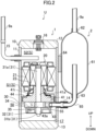
- a compressor unit (U) of this example is applied to a refrigeration apparatus (100).
- the refrigeration apparatus (100) is an air conditioner for conditioning air in a room, for example.
- the refrigeration apparatus (100) includes a refrigerant circuit (9).
- the refrigerant circuit (9) includes a compressor (1), an accumulator (2), a four-way switching valve (3), an outdoor heat exchanger (4), an expansion valve (5), and an indoor heat exchanger (6). These components are connected by a refrigerant pipe (9a).
- the refrigerant circuit (9) performs a refrigeration cycle where a refrigerant flows through the refrigerant pipe (9a) and circulates through the components.
- An outdoor unit (7) placed outdoors includes the compressor (1), the four-way switching valve (3), the outdoor heat exchanger (4), and the expansion valve (5).
- An indoor unit (8) placed indoors includes the indoor heat exchanger (6).
- the compressor unit (U) of this embodiment includes the compressor (1) and the accumulator (2).
- the compressor (1) and the accumulator (2) are of a vertical type.
- the compressor (1) and the accumulator (2) are fixed to each other by a fixing member (64) which will be described later.
- This compressor (1) is a rotary compressor.
- the compressor (1) compresses a refrigerant flowing through the refrigerant circuit.
- the compressor (1) includes a closed container (10), an electric motor (20), and a compression mechanism (30).
- the electric motor (20) and the compression mechanism (30) are housed in the closed container (10).
- the compressor (1) is of what is called a "high-pressure dome” type, where a refrigerant compressed in the compression mechanism (30) is discharged into an internal space (S) of the closed container (10) so that the pressure in the internal space (S) becomes high.
- the closed container (10) is vertically long. Specifically, the closed container (10) includes a cylindrical barrel (11) extending vertically, an upper end plate (12) closing an upper end of the barrel (11), and a lower end plate (13) closing a lower end of the barrel (11).
- the closed container (10) is an example of the first casing (10) of the present disclosure.
- the upper end plate (12) and the lower end plate (13) are relatively thick.
- the barrel (11) has a lower part provided with a suction pipe (14).
- the suction pipe (14) is relatively thick. Specifically, the difference between an inner diameter and an outer diameter of the suction pipe (14) is 1.0 mm to 2.8 mm, and is 2.8 mm in one preferred embodiment.
- the upper end plate (12) is provided with a discharge pipe (15) and a terminal (16) for supplying electric power to the electric motor (20).
- the refrigerant pipe (9a) is inserted into the discharge pipe (15).
- the closed container (10) has a bottom provided with an oil reservoir (17).
- the barrel (11) has an inner circumferential surface in substantially the middle of which a mounting plate (44) is fixed.
- the electric motor (20) is housed in the closed container (10).
- the electric motor (20) drives the compression mechanism (30).
- the internal space (S) is located above the mounting plate (44) inside the electric motor (20).
- the internal space (S) is divided into a first internal space (S1) below the electric motor (20) and a second internal space (S2) above the electric motor (20).
- the electric motor (20) includes a tubular stator (21) along the inner circumferential surface of the barrel (11), and a rotor (22) inside the stator (21).
- the drive shaft (31) extends vertically in the closed container (10).
- the drive shaft (31) is driven by the electric motor (20).
- the drive shaft (31) has a top part connected to the rotor (22) of the electric motor (20).
- the drive shaft (31) has a lower part including an upper shaft part (31a), an eccentric part (32), and a lower shaft part (31b) in this order from top to bottom.
- the eccentric part (32) is eccentric with respect to the center of the axis of the drive shaft (31).
- the eccentric part (32) has a diameter larger than those of the upper shaft part (31a) and the lower shaft part (31b).
- the compression mechanism (30) is housed in the closed container (10).
- the compression mechanism (30) compresses a sucked fluid and discharges the compressed fluid to the internal space (S) of the closed container (10).
- the compression mechanism (30) is placed on the lower surface of the mounting plate (44) and is fixed by the mounting plate (44).
- the compression mechanism (30) includes a drive shaft (31), a cylinder (34), a front head (41), a rear head (43), and a piston (35).
- the cylinder (34) is in a substantially cylindrical shape.
- the axis of the cylinder (34) extends vertically.
- the eccentric part (32) of the drive shaft (31) is inserted into the cylinder (34).
- the piston (35) is housed in the cylinder (34).
- the piston (35) slides on both the upper front head (41) and the lower rear head (43).
- the piston (35) includes a piston body (36) and a blade (37).
- the piston body (36) is in a ring shape. Specifically, the piston body (36) is in a slightly thick cylindrical shape.
- the eccentric part (32) of the drive shaft (31) is inserted slidably. When the drive shaft (31) rotates, the piston body (36) revolves along the inner circumferential surface of the cylinder (34).
- a compression chamber (50) is formed between the piston body (36) and the cylinder (34).
- the blade (37) is integral with the piston body (36).
- the blade (37) protrudes radially outward from an outer circumferential surface of the piston body (36).
- the blade (37) is sandwiched between a pair of swing bushes (54a, 54b) provided in a bush groove (53) extending radially outward from the inner circumferential surface of the cylinder (34).
- the blade (37) restricts the rotation of the piston body (36) when the piston body (36) revolves.
- the blade (37) divides the compression chamber (50) into a low-pressure chamber (51) and a high-pressure chamber (52).
- a suction port (55) penetrates the cylinder (34) radially.
- the suction port (55) has an inner circumferential end communicating with the low-pressure chamber (51) and an outer circumferential end connected to the suction pipe (14).
- the front head (41) is fixed to an upper end of the cylinder (34).
- the front head (41) closes the upper end of the cylinder (34).
- the front head (41) includes a bearing (41a) that rotatably supports the upper shaft part (31a) of the drive shaft (31).
- a discharge valve (41i) is provided in a discharge port (not shown) that communicates the high-pressure chamber (52) and the first internal space (S1). When the pressure of a refrigerant in the high-pressure chamber (52) reaches or exceeds a predetermined value, the discharge valve (41i) opens.
- the rear head (43) is fixed to a lower end of the cylinder (34).
- the rear head (43) closes the lower end of the cylinder (34).
- the rear head (43) includes a bearing (43a) that rotatably supports the lower shaft part (31b) of the drive shaft (31).
- the accumulator (2) temporarily stores a refrigerant sucked by the compressor (1).
- the accumulator (2) separates gas and liquid from each other. Specifically, the accumulator (2) separates a liquid refrigerant, refrigerating machine oil, and the like contained in a gaseous refrigerant.
- the accumulator (2) includes a casing (61), an outlet pipe (65), and the fixing member (64).
- the casing (61) is vertically long.
- the casing (61) is a closed container in a cylindrical shape.
- the casing (61) is an example of the second casing (61) of the present disclosure.
- the casing (61) is oriented to be vertically long.
- the second casing (61) is made of metal (e.g., iron).
- the casing (61) has an upper end provided with an inlet (62).
- the refrigerant pipe (9a) is inserted into the inlet (62).
- the inlet (62) and the refrigerant pipe (9a) are fixed to each other by welding, for example.
- a refrigerant in the refrigerant circuit (9) flows into the casing (61) through the inlet (62).
- the casing (61) has a lower end provided with an outlet (63).
- the outlet pipe (65) is inserted into the outlet (63).
- the outlet (63) and the outlet pipe (65) are fixed to each other by welding, for example.
- the outlet pipe (65) is made of metal (e.g., copper).
- the outlet pipe (65) has one end extending upward in the casing (61) from the outlet (63). This one end of the outlet pipe (65) is located above the middle of the casing (61).
- the outlet pipe (65) has another end inserted into the suction pipe (14). This other end of the outlet pipe (65) and the suction pipe (14) are fixed to each other by welding, for example.
- the fixing member (64) fixes the closed container (10) and the casing (61).
- the fixing member (64) is a metal plate member.
- the fixing member (64) includes a first surface (64a) in contact with the side surface (i.e., the barrel (11)) of the closed container (10), and two second surfaces (64b) in contact with the side surface of the casing (61) ( FIG. 4A ).
- the first surface (64a) curves along the side surface of the closed container (10).
- the first surface (64a) is in a rectangular shape.
- the two second surfaces (64b) are located at circumferential ends of the first surface (64a).
- the second surfaces (64b) are welded to the side surface of the casing (61) so that the fixing member (64) is fixed to the casing (61).
- the first surface (64a) includes projections (66) for welding (see FIG. 4B ).
- the projections (66) are located at four corners of the first surface (64a) before being welded.
- the first surface (64a) is fixed to the closed container (10).
- the first surface (64a) has a vertical length (i.e., a length along the cylinder shaft of the closed container) of 32 mm to 38 mm, and 38 mm in one preferred embodiment.
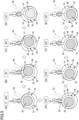
- a suction phase of sucking a refrigerant into the compression chamber (50) will be described.
- the drive shaft (31) slightly turns from an angle of 0° (the state in FIG. 4(A) )
- the contact point between the piston (35) and the cylinder (34) passes through the inner circumferential end of the suction port (55).
- the suction of a refrigerant into the low-pressure chamber (51) starts.
- a refrigerant is sucked from the suction pipe (14) through the suction port (55).
- the rotation angle of the drive shaft (31) increases, the volume of the low-pressure chamber (51) gradually increases, and then the amount of a refrigerant sucked into the low-pressure chamber (51) increases (the states in FIGS. 4(B) to 4(H)).
- This suction phase of sucking a refrigerant continues until the rotational angle of the drive shaft (31) reaches 360°, and then shifts to a discharge phase.
- the low-pressure chamber (51) connected to the suction port (55) serves as a high-pressure chamber (52) connected only to a discharge port (not shown). From this state, the compression of a refrigerant in the high-pressure chamber (52) starts. As the rotation angle of the drive shaft (31) increases, the volume of the high-pressure chamber (52) decreases, and then the pressure of the high-pressure chamber (52) increases. When the pressure of the high-pressure chamber (52) exceeds a predetermined value, the discharge valve (41i) opens. At this time, a refrigerant in the high-pressure chamber (52) is discharged through the discharge port (not shown) and flows into the first internal space (S 1).
- This gas refrigerant moves to the second internal space (S2) and then is discharged to the outside of the compressor (1) through the discharge pipe (15).
- the discharge phase of discharging a refrigerant continues until the rotational angle of the drive shaft (31) reaches 360°, and then shifts to the suction phase.
- the compressor (1) continuously performs the compression operation of a refrigerant by alternating the suction phase and the discharge phase in the compression chamber (50).
- the structural eigenvalue is a frequency specific to the accumulator and independent from the operation frequency of the compressor.
- the structural eigenvalue of the accumulator (2) of this example is around 500 Hz.
- the compressor unit (U) of this example is configured so that, at a frequency having a value three times larger than the maximum rotation speed of the compressor (1) when a first part is vibrated, an index showing a frequency response function of the casing (61) in the circumferential direction in a second part is 1.0 m/s 2 /N or less, where the first part is a part of an upper part of the side surface (the barrel (11)) of the closed container (10) and is orthogonal to the alignment direction of the compressor (1) and the accumulator (2), and the second part is a part of an upper part of the side surface of the casing (61) and is opposed to a part facing the closed container (10).
- the fixing member (64) is directly welded to the accumulator (2), and the fixing member (64) and the compressor (1) are welded at four points (i.e., the projections (66)).
- the suction pipe (14) is relatively thick, and the suction pipe (14) and the outlet pipe (65) are fixed by brazing.
- the fixing member (64) has a vertical width of 38 mm.
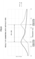
- the compressor of this example operated at the maximum rotation speed of 138 rps has a relatively high influence on the circumferential vibration acceleration at an upper part of the casing (61) of the accumulator (2) of this example. For example, there was less influence on the radial vibration acceleration at the upper part of the surface of the casing (61) than the circumferential vibration acceleration.
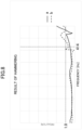
- the solid line (a) shows the circumferential vibration acceleration at the upper part of the surface of the casing (61) of the accumulator (2) of this example.
- the broken line (b) shows the circumferential vibration acceleration at an upper part of a casing surface of a typical accumulator.
- the compressor unit (U) of this example and the typical compressor unit are different in vibration characteristics where the compressor is in operation. Note that both of the compressor units are connected with the refrigerant pipe (9a).
- the circumferential vibration acceleration at an upper part of the casing surface of the accumulator may be simply referred to as a vibration acceleration.
- a vibration acceleration when the compressor operates at the maximum rotation speed and interference is prevented between the structural eigenvalue of the accumulator and the 3N-frequency component of the electric motor is defined as a target vibration acceleration.
- the target vibration acceleration where the rotation speed of the compressor is the maximum rotation speed of 138 rps is 8 m/s 2 or less.
- the vibration acceleration is 8 m/s 2 or less, interference is prevented between the structural eigenvalue of the accumulator (2) and the 3N-frequency component of the electric motor, thereby reducing the vibration on the surface of the casing (61) of the accumulator (2).
- the compressor unit (U) of this example when the compressor (1) operates at a rotation speed of 138 rps, the compressor unit (U) of this example exhibits a vibration acceleration of 8 m/s 2 or less. This satisfies the requirement of the target vibration acceleration.
- the typical compressor unit exhibits a vibration acceleration 8 m/s 2 or more when the compressor operates at a rotation speed of 138 rps. This fails to satisfy the requirement of the target vibration acceleration.
- the compressor unit (U) of this example can prevent interference between the frequency of the accumulator (around 500 hz) and the 3N-frequency component of the electric motor (20), thereby reducing the vibration of the accumulator (2).
- a hammering test was conducted to reproduce the characteristics of the compressor unit (U) of this example. It can be confirmed through the hammering test whether the compressor unit (U) can reduce the vibration on the surface of the accumulator (2) without actual operation of the compressor (1).
- the compressor (1) on an elastic member such as rubber was vibrated by a hammer (Model No. 086C01 manufactured by PCB Co., Ltd.), and the response was analyzed based on a value detected by an acceleration sensor (Model No. 3263A1 manufactured by DYTRAN Co., Ltd.) attached to an upper part of the surface of the accumulator (2).
- the analysis was conducted by using a piece of analysis software (manufactured by National Instruments Corporation) with the frequency response function (FRF) of the side surface of the casing (61) in the circumferential direction.
- FRF frequency response function
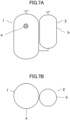
- the vibration position is a first part ((a) in FIG. 7 ) which is a part of an upper part of the side surface of the closed container (10) and which is orthogonal to the alignment direction of the compressor (1) and the accumulator (2).
- This part is the first part of the present disclosure.
- the response position is a second part ((b) in FIG. 7 ) which is a part of an upper part of the side surface of the casing (61) and which is opposed to a part facing the closed container (10).
- the FRF of the second part in the circumferential direction of the casing (61) when the first part is vibrated exhibited the same behavior as when the compressor (1) is in operation.
- the first part was regarded as a vibration position, and the second part as a response position.
- the index showing the frequency response function (FRF) of this example is the accelerance (acceleration/force (m/s 2 /N)).
- FIG. 8 shows the vibration characteristics of the accumulators of the compressor unit (U) of this example (the solid line (a)) and the typical compressor unit (the broken line (b)), where the horizontal axis shows the frequency (Hz) and the vertical axis shows the FRF (m/s 2 /N).
- a frequency having around a value three times larger than the maximum rotation speed of the compressor, which is a 3N-frequency component of the electric motor is defined as a first frequency.
- an FRF which prevents interference between the frequency (around 500 Hz) of the accumulator and the 3N-frequency component of the electric motor (20) is defined as a target FRF .
- the first frequency was set to 414 Hz, where the maximum rotation speed of the compressor was 138 rps.
- the target FRF was set to 1.0 m/s 2 /N or less.
- the FRF of the compressor unit (U) of this example at 414 Hz was 0.92 m/s 2 /N.
- the FRF of the typical compressor unit at a frequency around 414 Hz was 1.02 m/s 2 /N. Accordingly, the compressor unit (U) of this example satisfies the target FRF, while the typical compressor unit (U) fails to satisfy the target FRF.
- the circumferential vibration acceleration at the upper part of the surface of the accumulator satisfies the target vibration acceleration of 8.0 m/s 2 or less when the compressor (1) operates at a rotation speed of 138 rps. It is shown on the other hand that the typical compressor unit fails to satisfy the target vibration acceleration.
- the FRF (m/s 2 /N) correlates with the circumferential vibration acceleration (m/s 2 ) at an upper part of the side surface of the casing (61) of the accumulator (2).
- the compressor unit (U) of this example and the typical compressor unit (U) each exhibited a correlation coefficient of 0.70 or more.
- the compressor unit (U) of this example is configured so that, at a first frequency having a value three times larger than the maximum rotation speed of the compressor (1) when a first part is vibrated, an index showing a frequency response function of the casing (61) in the circumferential direction in a second part is 1.0 m/s 2 /N or less, where the first part is a part of an upper part of the side surface of the closed container (10) (the first casing) of the compressor (1) and is orthogonal to the alignment direction of the compressor (1) and the accumulator (2), and the second part is a part of an upper part of the side surface of the casing (61) (the second casing) of the accumulator (2) and is opposed to a part facing the closed container (10).
- the index of the frequency response function of the casing (61) in the circumferential direction in the second part when the first part is vibrated is 1.0 m/s 2 /N or less, where the refrigerant pipe (9a) connected to the discharge pipe (15) of the compressor (1) and the suction pipe (14) of the accumulator (2).
- the compressor unit (U) of this example further includes a fixing member (64) having a plate shape; provided between the closed container (10) and the casing (61); and fixing the closed container (10) and the casing (61).
- the fixing member (64) has a first surface (64a) having a rectangular shape curving along the side surface of the closed container (10), and includes the first surface (64a) having four corners fixed to the closed container (10) by welding.
- the four corners (four points) of the first surface (64a) of the fixing member (64) is welded to the closed container (10), and thus the index showing the frequency response function of the casing (61) in the circumferential direction in the second part when the first part is vibrated can be 1.0 m/s 2 /N or less. This can reliably reduce an increase in the vibration on the surface of the casing (61) of the accumulator (2).
- the maximum rotation speed of the compressor (1) is 120 rps or more.
- the compressor (1) operates at a rotation speed of 120 rps or more, an increase in the vibration on the surface of the casing (61) of the accumulator (2) can be reduced.
- the hammering test was conducted under the same conditions as those of the embodiment described above, with the refrigerant pipe (9a) detached from the compressor unit (U).
- the solid line (a) in FIG. 9 shows a test result where the refrigerant pipe (9a) is attached.
- the dashed line (b) in FIG. 9 shows a test result where the refrigerant pipe (9a) is detached.
- the structural eigenvalue of the accumulator (2) is higher by about 15% to 20% than where the refrigerant pipe (9a) is connected. Accordingly, the first frequency of the compressor unit (U) where the refrigerant pipe (9a) is not connected is higher by about 15% to 20%, i.e., about 1.15 times to 1.20 times than that of the compressor unit (U) where the refrigerant pipe (9a) is connected.
- the first frequency is 476 Hz to 496 Hz, which is a value obtained by multiplying a value three times larger than about 138 rps by 1.15 to 1.20. That is, in the compressor unit (U) of this example where the refrigerant pipe (9a) is not connected, the FRF from about 476 Hz to about 496 Hz satisfies 1.0 m/s 2 /N or less.
- the above embodiment may also be configured as follows.
- the maximum rotation speed of the compressor (1) only has to be 120 rps or more.
- the rotation speed is 120 rps or more and the FRF at the first frequency satisfies 1.0 m/s 2 /N or less
- the circumferential vibration acceleration is 8 m/s 2 or less at an upper part of the side surface of the casing (61) of the accumulator (2). This can reduce an increase in the vibration on the surface of the accumulator (2).
- the first frequency only has to be within a frequency range between a frequency having a value three times larger than the maximum rotation speed of the compressor (1) and a frequency 1.25 times greater than the frequency having a value three times larger than the maximum rotation speed of the compressor (1).
- this frequency range when the FRF satisfies 1.0 m/s 2 /N or less, interference can be prevented between the structural eigenvalue of the accumulator (2) and the 3N-component of the compressor (1), and this can reduce an increase in the vibration on the surface of the accumulator (2).
- the compressor unit (U) may include an elastic member fixed between the compressor (1) and the accumulator (2). This can attenuate propagation of the vibration from the compressor (1) to the accumulator (2). This can lower the level of response of the accumulator to the vibration from the compressor (1), and this can reduce an increase in the vibration on the surface of the accumulator (2).
- the outlet pipe (65) of the accumulator (2) may have a larger thickness, or a resin putty may be applied on the upper surface of the accumulator (2). This can reduce the vibration on the surface of the accumulator even when the compressor (1) rotates at the maximum rotation speed.
- the compressor (1) of the compressor unit (U) may be a swing rotary compressor as in the above embodiment, or may be a rotary compressor with a vane.
- the present disclosure is useful for a compressor unit.
Landscapes
- Engineering & Computer Science (AREA)
- Mechanical Engineering (AREA)
- General Engineering & Computer Science (AREA)
- Applications Or Details Of Rotary Compressors (AREA)
- Compressor (AREA)
Applications Claiming Priority (2)
| Application Number | Priority Date | Filing Date | Title |
|---|---|---|---|
| JP2021161006A JP7143496B1 (ja) | 2021-09-30 | 2021-09-30 | 圧縮機ユニット |
| PCT/JP2022/022356 WO2023053578A1 (ja) | 2021-09-30 | 2022-06-01 | 圧縮機ユニット |
Publications (2)
| Publication Number | Publication Date |
|---|---|
| EP4411136A1 true EP4411136A1 (de) | 2024-08-07 |
| EP4411136A4 EP4411136A4 (de) | 2025-01-29 |
Family
ID=83444697
Family Applications (1)
| Application Number | Title | Priority Date | Filing Date |
|---|---|---|---|
| EP22875457.8A Pending EP4411136A4 (de) | 2021-09-30 | 2022-06-01 | Verdichtereinheit |
Country Status (5)
| Country | Link |
|---|---|
| US (1) | US12429055B2 (de) |
| EP (1) | EP4411136A4 (de) |
| JP (2) | JP7143496B1 (de) |
| CN (1) | CN117980603A (de) |
| WO (1) | WO2023053578A1 (de) |
Families Citing this family (2)
| Publication number | Priority date | Publication date | Assignee | Title |
|---|---|---|---|---|
| JP2024113954A (ja) * | 2023-02-10 | 2024-08-23 | 株式会社富士通ゼネラル | 圧縮機 |
| CN120537730A (zh) * | 2024-05-22 | 2025-08-26 | 上海海立电器有限公司 | 压缩机壳盖和壳体的装配结构及压缩机 |
Family Cites Families (15)
| Publication number | Priority date | Publication date | Assignee | Title |
|---|---|---|---|---|
| JP2001317479A (ja) | 2000-05-11 | 2001-11-16 | Matsushita Electric Ind Co Ltd | 縦置型圧縮機 |
| KR100498379B1 (ko) * | 2002-11-20 | 2005-07-01 | 엘지전자 주식회사 | 밀폐형 회전식 압축기의 진동저감구조 |
| JP2007255332A (ja) * | 2006-03-24 | 2007-10-04 | Daikin Ind Ltd | 圧縮機 |
| JP5665291B2 (ja) * | 2009-09-03 | 2015-02-04 | 新日鐵住金株式会社 | 密閉型電動圧縮機 |
| WO2011034164A1 (ja) * | 2009-09-18 | 2011-03-24 | 東芝キヤリア株式会社 | 多気筒ロータリ式圧縮機と冷凍サイクル装置 |
| JP2012026273A (ja) * | 2010-07-20 | 2012-02-09 | Hitachi Appliances Inc | 密閉型圧縮機 |
| KR101718037B1 (ko) * | 2010-12-29 | 2017-03-20 | 엘지전자 주식회사 | 밀폐형 압축기 |
| KR20140112317A (ko) * | 2013-03-13 | 2014-09-23 | 엘지전자 주식회사 | 압축기 |
| JP6408808B2 (ja) * | 2014-07-10 | 2018-10-17 | 三菱重工サーマルシステムズ株式会社 | 電動圧縮機 |
| JP6090405B1 (ja) * | 2015-10-16 | 2017-03-08 | ダイキン工業株式会社 | 圧縮機 |
| JP6645845B2 (ja) * | 2016-01-26 | 2020-02-14 | 三菱重工サーマルシステムズ株式会社 | 複数の配管を有するアキュムレータおよび圧縮機 |
| WO2017216875A1 (ja) * | 2016-06-14 | 2017-12-21 | 三菱電機株式会社 | ロータリー圧縮機 |
| JP2018035711A (ja) * | 2016-08-30 | 2018-03-08 | ダイキン工業株式会社 | 圧縮機ユニット |
| JP7175860B2 (ja) * | 2019-08-23 | 2022-11-21 | 株式会社東芝 | 圧縮機及び空調装置 |
| JP7256421B1 (ja) * | 2021-09-30 | 2023-04-12 | ダイキン工業株式会社 | 圧縮機ユニット及び冷凍装置 |
-
2021
- 2021-09-30 JP JP2021161006A patent/JP7143496B1/ja active Active
-
2022
- 2022-06-01 WO PCT/JP2022/022356 patent/WO2023053578A1/ja not_active Ceased
- 2022-06-01 CN CN202280064403.5A patent/CN117980603A/zh active Pending
- 2022-06-01 EP EP22875457.8A patent/EP4411136A4/de active Pending
- 2022-09-12 JP JP2022144589A patent/JP7348568B2/ja active Active
-
2024
- 2024-03-28 US US18/621,027 patent/US12429055B2/en active Active
Also Published As
| Publication number | Publication date |
|---|---|
| JP7143496B1 (ja) | 2022-09-28 |
| CN117980603A (zh) | 2024-05-03 |
| JP2023051779A (ja) | 2023-04-11 |
| EP4411136A4 (de) | 2025-01-29 |
| JP2023050743A (ja) | 2023-04-11 |
| JP7348568B2 (ja) | 2023-09-21 |
| US12429055B2 (en) | 2025-09-30 |
| US20240240639A1 (en) | 2024-07-18 |
| WO2023053578A1 (ja) | 2023-04-06 |
Similar Documents
| Publication | Publication Date | Title |
|---|---|---|
| US12429055B2 (en) | Compressor unit | |
| CN103906928B (zh) | 密闭型旋转式压缩机和制冷循环装置 | |
| US9748815B2 (en) | Rotary compressor with the balance weight formed with a recess for receiving the head of a rivet | |
| EP4390129A1 (de) | Verdichtereinheit und kühlvorrichtung | |
| EP4488589B1 (de) | Wärmequelleneinheit und spiralverdichter | |
| EP4008906B1 (de) | Rotationsverdichter | |
| JP5228719B2 (ja) | 二段圧縮機 | |
| WO2024085066A1 (ja) | 電動圧縮機 | |
| JP6704555B1 (ja) | 圧縮機及び冷凍サイクル装置 | |
| EP4502385A1 (de) | Rotationsverdichter und kühlvorrichtung | |
| JP7288237B1 (ja) | 圧縮機および冷凍装置 | |
| CN117889083B (zh) | 泵组件、压缩机和制冷设备 | |
| EP4390133A1 (de) | Verdichtereinheit und kühlvorrichtung | |
| EP4455484A1 (de) | Rotationsverdichter und klimaanlage | |
| JP7470567B2 (ja) | 圧縮機及び冷凍サイクル装置 | |
| JP2026020868A (ja) | 圧縮機ユニット | |
| JP2023162674A (ja) | 圧縮機における冷媒としての使用、圧縮機、および、冷凍サイクル装置 | |
| WO2026028542A1 (ja) | 圧縮機ユニット | |
| AU2023242477A1 (en) | Compressor and air conditioner | |
| KR20010110149A (ko) | 밀폐형 압축기 | |
| Crocker | Noise and vibration in reciprocating and rotary compressors: a review | |
| JP2018013102A (ja) | 圧縮機 | |
| WO2020039489A1 (ja) | 圧縮機、及び、これを備える冷凍サイクル装置 |
Legal Events
| Date | Code | Title | Description |
|---|---|---|---|
| STAA | Information on the status of an ep patent application or granted ep patent |
Free format text: STATUS: THE INTERNATIONAL PUBLICATION HAS BEEN MADE |
|
| PUAI | Public reference made under article 153(3) epc to a published international application that has entered the european phase |
Free format text: ORIGINAL CODE: 0009012 |
|
| STAA | Information on the status of an ep patent application or granted ep patent |
Free format text: STATUS: REQUEST FOR EXAMINATION WAS MADE |
|
| 17P | Request for examination filed |
Effective date: 20240326 |
|
| AK | Designated contracting states |
Kind code of ref document: A1 Designated state(s): AL AT BE BG CH CY CZ DE DK EE ES FI FR GB GR HR HU IE IS IT LI LT LU LV MC MK MT NL NO PL PT RO RS SE SI SK SM TR |
|
| DAV | Request for validation of the european patent (deleted) | ||
| DAX | Request for extension of the european patent (deleted) | ||
| A4 | Supplementary search report drawn up and despatched |
Effective date: 20250108 |
|
| RIC1 | Information provided on ipc code assigned before grant |
Ipc: F04C 29/12 20060101ALI20241223BHEP Ipc: F04C 29/06 20060101ALI20241223BHEP Ipc: F04B 39/00 20060101AFI20241223BHEP |
|
| P01 | Opt-out of the competence of the unified patent court (upc) registered |
Free format text: CASE NUMBER: APP_1036/2025 Effective date: 20250108 |
|
| STAA | Information on the status of an ep patent application or granted ep patent |
Free format text: STATUS: EXAMINATION IS IN PROGRESS |
|
| 17Q | First examination report despatched |
Effective date: 20250916 |