EP4411095B1 - Beschlaganordnung sowie tür- oder fensteranordnung für eine solche beschlaganordnung - Google Patents
Beschlaganordnung sowie tür- oder fensteranordnung für eine solche beschlaganordnung Download PDFInfo
- Publication number
- EP4411095B1 EP4411095B1 EP23154576.5A EP23154576A EP4411095B1 EP 4411095 B1 EP4411095 B1 EP 4411095B1 EP 23154576 A EP23154576 A EP 23154576A EP 4411095 B1 EP4411095 B1 EP 4411095B1
- Authority
- EP
- European Patent Office
- Prior art keywords
- control lever
- main lever
- fitting arrangement
- lever
- arrangement
- Prior art date
- Legal status (The legal status is an assumption and is not a legal conclusion. Google has not performed a legal analysis and makes no representation as to the accuracy of the status listed.)
- Active
Links
Images


Classifications
-
- E—FIXED CONSTRUCTIONS
- E05—LOCKS; KEYS; WINDOW OR DOOR FITTINGS; SAFES
- E05D—HINGES OR SUSPENSION DEVICES FOR DOORS, WINDOWS OR WINGS
- E05D15/00—Suspension arrangements for wings
- E05D15/48—Suspension arrangements for wings allowing alternative movements
- E05D15/52—Suspension arrangements for wings allowing alternative movements for opening about a vertical as well as a horizontal axis
- E05D15/5214—Corner supports
-
- E—FIXED CONSTRUCTIONS
- E05—LOCKS; KEYS; WINDOW OR DOOR FITTINGS; SAFES
- E05D—HINGES OR SUSPENSION DEVICES FOR DOORS, WINDOWS OR WINGS
- E05D11/00—Additional features or accessories of hinges
- E05D11/06—Devices for limiting the opening movement of hinges
-
- E—FIXED CONSTRUCTIONS
- E05—LOCKS; KEYS; WINDOW OR DOOR FITTINGS; SAFES
- E05Y—INDEXING SCHEME ASSOCIATED WITH SUBCLASSES E05D AND E05F, RELATING TO CONSTRUCTION ELEMENTS, ELECTRIC CONTROL, POWER SUPPLY, POWER SIGNAL OR TRANSMISSION, USER INTERFACES, MOUNTING OR COUPLING, DETAILS, ACCESSORIES, AUXILIARY OPERATIONS NOT OTHERWISE PROVIDED FOR, APPLICATION THEREOF
- E05Y2201/00—Constructional elements; Accessories therefor
- E05Y2201/60—Suspension or transmission members; Accessories therefor
- E05Y2201/622—Suspension or transmission members elements
- E05Y2201/624—Arms
- E05Y2201/626—Levers
-
- E—FIXED CONSTRUCTIONS
- E05—LOCKS; KEYS; WINDOW OR DOOR FITTINGS; SAFES
- E05Y—INDEXING SCHEME ASSOCIATED WITH SUBCLASSES E05D AND E05F, RELATING TO CONSTRUCTION ELEMENTS, ELECTRIC CONTROL, POWER SUPPLY, POWER SIGNAL OR TRANSMISSION, USER INTERFACES, MOUNTING OR COUPLING, DETAILS, ACCESSORIES, AUXILIARY OPERATIONS NOT OTHERWISE PROVIDED FOR, APPLICATION THEREOF
- E05Y2201/00—Constructional elements; Accessories therefor
- E05Y2201/60—Suspension or transmission members; Accessories therefor
- E05Y2201/622—Suspension or transmission members elements
- E05Y2201/638—Cams; Ramps
-
- E—FIXED CONSTRUCTIONS
- E05—LOCKS; KEYS; WINDOW OR DOOR FITTINGS; SAFES
- E05Y—INDEXING SCHEME ASSOCIATED WITH SUBCLASSES E05D AND E05F, RELATING TO CONSTRUCTION ELEMENTS, ELECTRIC CONTROL, POWER SUPPLY, POWER SIGNAL OR TRANSMISSION, USER INTERFACES, MOUNTING OR COUPLING, DETAILS, ACCESSORIES, AUXILIARY OPERATIONS NOT OTHERWISE PROVIDED FOR, APPLICATION THEREOF
- E05Y2201/00—Constructional elements; Accessories therefor
- E05Y2201/60—Suspension or transmission members; Accessories therefor
- E05Y2201/622—Suspension or transmission members elements
- E05Y2201/682—Pins
-
- E—FIXED CONSTRUCTIONS
- E05—LOCKS; KEYS; WINDOW OR DOOR FITTINGS; SAFES
- E05Y—INDEXING SCHEME ASSOCIATED WITH SUBCLASSES E05D AND E05F, RELATING TO CONSTRUCTION ELEMENTS, ELECTRIC CONTROL, POWER SUPPLY, POWER SIGNAL OR TRANSMISSION, USER INTERFACES, MOUNTING OR COUPLING, DETAILS, ACCESSORIES, AUXILIARY OPERATIONS NOT OTHERWISE PROVIDED FOR, APPLICATION THEREOF
- E05Y2201/00—Constructional elements; Accessories therefor
- E05Y2201/60—Suspension or transmission members; Accessories therefor
- E05Y2201/622—Suspension or transmission members elements
- E05Y2201/71—Toothed gearing
- E05Y2201/712—Toothed gearing with incomplete toothing
-
- E—FIXED CONSTRUCTIONS
- E05—LOCKS; KEYS; WINDOW OR DOOR FITTINGS; SAFES
- E05Y—INDEXING SCHEME ASSOCIATED WITH SUBCLASSES E05D AND E05F, RELATING TO CONSTRUCTION ELEMENTS, ELECTRIC CONTROL, POWER SUPPLY, POWER SIGNAL OR TRANSMISSION, USER INTERFACES, MOUNTING OR COUPLING, DETAILS, ACCESSORIES, AUXILIARY OPERATIONS NOT OTHERWISE PROVIDED FOR, APPLICATION THEREOF
- E05Y2800/00—Details, accessories and auxiliary operations not otherwise provided for
- E05Y2800/40—Physical or chemical protection
- E05Y2800/412—Physical or chemical protection against friction
-
- E—FIXED CONSTRUCTIONS
- E05—LOCKS; KEYS; WINDOW OR DOOR FITTINGS; SAFES
- E05Y—INDEXING SCHEME ASSOCIATED WITH SUBCLASSES E05D AND E05F, RELATING TO CONSTRUCTION ELEMENTS, ELECTRIC CONTROL, POWER SUPPLY, POWER SIGNAL OR TRANSMISSION, USER INTERFACES, MOUNTING OR COUPLING, DETAILS, ACCESSORIES, AUXILIARY OPERATIONS NOT OTHERWISE PROVIDED FOR, APPLICATION THEREOF
- E05Y2900/00—Application of doors, windows, wings or fittings thereof
- E05Y2900/10—Application of doors, windows, wings or fittings thereof for buildings or parts thereof
- E05Y2900/13—Type of wing
- E05Y2900/148—Windows
Definitions
- the invention relates to a fitting arrangement for a door or window arrangement with features of claim 1 and a door or window arrangement with features of the independent claim.
- Fitting arrangements for door or window arrangements are known from the state of the art. These are used, for example, to pivotally mount a wing of a door or window arrangement on a frame of the door or window arrangement.
- Such fitting arrangements are, for example, in EP 2 703 587 B1 , which shows a fitting arrangement with features of the preamble of claim 1, and EP 2 444 578 A2 revealed.
- EP 3 480 398 a fitting arrangement with a fixed and a movable arm, which are coupled by means of several levers and connected by means of a connection system to a designed frames can be coupled.
- GB 2 279 695 A and JP 2019-183462 A each disclose a fitting arrangement for pivotably connecting a sash to a frame, wherein the fitting arrangement has two levers which are coupled to one another by gears.
- the above object is achieved by a fitting arrangement with the features of claim 1.
- the fitting arrangement can be designed as a corner bearing.
- the fitting arrangement is designed and/or intended for an arrangement, in particular a concealed arrangement, in a door or window arrangement with a frame and a sash that can be pivoted relative to the frame.
- a concealed arrangement means in particular an arrangement in a rebate between the frame and the sash (window rebate or door rebate).
- the fitting arrangement can be a turning fitting arrangement or a tilt and turn fitting arrangement.
- the fitting arrangement comprises a fastening element for fastening to the frame.
- the fastening element can be fastened to the frame by screwing, for example.
- the fastening element can be designed as a corner bearing angle.
- the fitting arrangement comprises a main lever pivotably mounted on or on the fastening element.
- the main lever can be designed to at least partially absorb the weight of the sash (load transfer). In other words, the weight of the sash can at least partially rest on the main lever.
- the main lever is designed to pivot about a main lever pivot axis that is immovable relative to the fastening element.
- the fitting arrangement comprises a control lever pivotably mounted on or on the fastening element.
- the control lever is designed to pivot about a control lever pivot axis that is immovable relative to the fastening element.
- the control lever is designed and/or intended to pivot the main lever.
- the fitting arrangement can be implemented with just a few components, thus reducing the complexity of the fitting arrangement. This simplifies the kinematics and makes the fitting arrangement particularly robust. In addition, the reliability can be increased.
- control lever comprises a drive section for driving the main lever and the main lever comprises an output element arranged fixedly on the main lever.
- the output element can be connected or coupled to the main lever in a rotationally fixed manner, in particular with respect to the main lever pivot axis.
- the output element is arranged along the direction of gravity below the main lever (on its underside).
- the output element serves in particular as the output of the control lever or its drive section.
- the output element and the main lever can be designed in two parts (two separate components) or in one part (as one component).
- the drive section and the output element can engage with one another.
- the drive section and the output element can engage with one another during the pivoting of the main lever and/or the control lever.
- the drive section and the output element can have mutually corresponding engagement sections.
- the drive section and the output element can be designed as gears or gear segments (engagement sections).
- the drive section can have a rounded extension.
- the output element can be (essentially) circular ring-shaped or U-shaped.
- the extension can engage in the circular ring-shaped or U-shaped output element during the pivoting of the main lever and/or the control lever.
- the fastening element can comprise a sliding section.
- the output element can be set up (e.g. arranged and/or aligned accordingly) to slide on the sliding section during the pivoting of the main lever and/or the control lever.
- the output element in particular contacts the sliding section of the fastening element.
- the output element can thus serve as a support, so to speak as a "support" for the main lever.
- the force acting on the main lever due to the weight of the wing, particularly during pivoting of the main lever and/or the control lever, can be at least partially dissipated via the output element.
- the load acting on the main lever can thus be distributed or evened out. This can further reduce wear, particularly on the main lever.
- the sliding section can comprise a sliding plate.
- the output element and the sliding plate can be designed such that the output element slides on the sliding plate during the pivoting of the main lever and/or the control lever.
- the sliding plate can be designed as a stainless steel plate.
- the sliding plate can be made of stainless steel.
- the fitting arrangement can comprise a control lever bolt.
- the control lever can be pivotably mounted on or at the fastening element by means of the control lever bolt.
- the control lever bolt can protrude from the control lever.
- the control lever bolt can form a Form a sliding surface for the main lever, particularly during pivoting of the main lever and/or the control lever.
- the main lever can in particular contact the front surface of the control lever bolt with its underside (in relation to the direction of gravity).
- the control lever bolt can thus serve as a support ("support") for the main lever.
- the fitting arrangement according to the invention comprises a corner hinge for fastening to the sash.
- the corner hinge can be pivotably mounted on or on the main lever, in particular by means of a main lever bolt.
- the corner hinge and thus the sash connected to the corner hinge can thus be pivoted around the main lever, in particular around the main lever bolt (rotational movement).
- a drive bolt is arranged on the control lever.
- the drive bolt is at least partially (in particular completely) guided so that it can move within a guide arranged in the corner hinge, in particular in a straight line.
- the guide can be designed as a straight guide.
- the guide can be designed as an elongated hole.
- the drive bolt can be arranged so that it can move within the guide. This can facilitate the pivoting of the control lever by pivoting (rotating movement) of the sash or the corner hinge connected to the sash, in particular around the main lever bolt.
- the pivoting of the corner hinge or the sash connected to the corner hinge leads in particular to a pivoting of the control lever and thus to a pivoting of the main lever on which the corner hinge is pivotably mounted.
- the pivoting of the corner hinge thus leads to a movement of the corner hinge consisting of two superimposed pivoting movements.
- the superimposed pivoting movement consists in particular of a pivoting of the corner hinge (first rotary movement) around the main lever pin and a pivoting of the corner hinge (second rotary movement) around the main lever pivot axis.
- the main lever can at least partially, in particular completely, cover the drive section and the output element in an open position and in a closed position of the fitting arrangement (with respect to the direction of gravity).
- control lever can comprise a protective section.
- the protective section can be designed to at least partially, in particular completely, engage behind the output element (and/or the drive section) in an open position of the fitting arrangement.
- the protective section of the control lever can thus at least partially overlap the output element in an open position (in relation to a direction oriented perpendicular to the direction of gravity).
- the output element (and/or the drive section) can be shielded and protected from external influences (e.g. wind, dirt, water), especially coming from outside through an open wing.
- external influences e.g. wind, dirt, water
- the protective section can be designed as part of the drive section.
- the protective section can be arranged directly adjacent to the drive section.
- the object mentioned at the beginning is also achieved by a door or window arrangement with the features of the independent claim.
- the door or window arrangement comprises a frame and a wing pivotably mounted on the frame by means of a fitting arrangement as described above.
- a fitting arrangement as described above.
- the sash can be pivotally mounted on the fitting arrangement and can be pivoted relative to the frame between a closed position (sash is in or on the frame plane) and an open position (sash is pivoted open relative to the frame plane).
- the window arrangement can be a turn window arrangement or a turn tilt window arrangement.
- the door arrangement can be a turn door arrangement or a turn tilt door arrangement.
- the fitting arrangement can be arranged at least partially, in particular completely, in a rebate (window rebate or door rebate) between the frame and the sash.
- Figure 1 shows a perspective view of a window arrangement 12 with a fitting arrangement 10.
- the window arrangement 12 comprises a frame 14 and a sash 16 which can be pivoted relative to the frame 14.
- the sash 16 is pivotally mounted on the frame 14 by means of the fitting arrangement 10.
- the fitting arrangement 10 is arranged in a rebate 56 between the frame 14 and the sash 16 of the window arrangement 12.
- the fitting arrangement 10 is arranged in a lower corner of the frame 14 (with respect to the direction of gravity 15), in the rebate 56 (window rebate).
- the direction of gravity 15 is in Figure 1 indicated by an arrow.
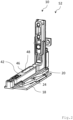
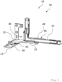
- Figure 2 shows a perspective view of the fitting arrangement 10 according to Figure 1 in a closed position 52 and Figure 3 in an open position 50.
- the fitting arrangement 10 comprises a fastening element 18 for fastening the fitting arrangement 10 to the frame 14.
- the fastening element 18 is designed in the example as a corner bearing angle.
- the fitting arrangement 10 further comprises a main lever 20 pivotably mounted on or at the fastening element 18.
- the main lever 20 is designed to pivot about an immovable main lever pivot axis 22.
- the fitting arrangement 10 also comprises a control lever 24 pivotably mounted on or at the fastening element 18.
- the control lever 24 is designed to pivot about an immovable control lever pivot axis 26 (cf. Figure 4 ) designed to be pivotable.
- the fitting arrangement 10 comprises a corner hinge 42 which is connected to the sash 16 (cf. Figure 1 ).
- the corner hinge 42 is pivotally mounted on or on the main lever 20 by means of a main lever bolt 44.
- the weight of the sash 16 (and the corner hinge 42) is thus at least partially supported on the main lever 20.
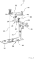
- Figure 4 shows an exploded view of the fitting arrangement 10 according to Figure 1 , whereby the corner band 42 is in the Figure 4 is not shown.
- the main lever pivot axis 22 and the control lever pivot axis 26 are each immovable with respect to the fastening element 18.
- the control lever 24 has a drive section 28 for driving the main lever 20.
- the drive section 28 and the output element 30 are during pivoting of the main lever 20 and/or the control lever 24.
- the output element 30 is designed in the shape of a circular ring or U-shaped and the drive section 28 of the control lever 24 has a rounded extension 32.
- the extension 32 engages in the output element 30. The pivoting movement of the main lever 20 and/or the control lever 24 is described in detail below.
- the control lever 24 has a protective section 54 which is designed to at least partially engage behind the output element 30 in an open position 50 of the fitting arrangement 10 (cf. Figure 6 ).
- the fastening element 18 has a sliding section 34 in the present case.
- the sliding section 34 comprises a sliding plate 36.
- the output element 30 guides on the sliding section 34 or the sliding plate 36.
- the fitting arrangement 10 has a control lever bolt 38.
- the control lever 24 is pivotably mounted on or at the fastening element 18 by means of the control lever bolt 38.
- the control lever 24 is designed to be pivotable about the control lever bolt 38.
- the control lever bolt 38 protrudes from the control lever 24 and forms, with its The front side 40 protruding from the control lever 24 provides a sliding surface for the main lever 20.
- the main lever 20 is thus additionally supported by the output element 30 and the control lever bolt 38. This allows the weight of the wing 16 exerted on the main lever 20 to be distributed more evenly and thus wear to be reduced.
- the control lever 24 has a drive pin 46.
- the drive pin 46 engages in a guide 48 formed in the corner hinge 42 (cf. Figure 2 and 3 ).
- the drive bolt 46 is guided straight within the corner hinge 42 by means of the guide 48.
- the guide 48 is designed in the form of an elongated hole.
- Figure 5 shows a plan view of the fitting arrangement 10 according to Figure 1 in the closed position 52 and Figure 6 shows a plan view of the fitting arrangement 10 according to Figure 1 in the open position 50.
- the corner hinge 42 is for reasons of better overview in Figure 5 and 6 not shown.
- the functionality of the fitting arrangement 10 and its kinematics are explained below:
- the closed position 52 ( Figure 5 ) of the fitting arrangement 10 is the window arrangement 12 or the sash 16 (cf. Figure 1 ) is also in a closed position.
- the wing 16 is closed or swung in.
- the open position 50 ( Figure 6 ) of the fitting arrangement 10 is also the Window arrangement 12 (cf. Figure 1 ) is also in an open position or in other words, the wing 16 is opened or swung open.
- the corner hinge 42 connected to the sash 16 is pivoted about the main lever pin 44. Since the drive pin 46 is guided straight within the guide 48 of the corner hinge 42, pivoting the sash 16 and thus the corner hinge 42 causes the control lever 24 to pivot (pivot) about the control lever pivot axis 26.
- the extension 32 moves about the control lever pivot axis 26 and engages in the circular segment-shaped or U-shaped output element 30.
- the output element 30 and thus the main lever 20 are pivoted about the main lever pivot axis 22.
- the main lever pin 44 is also pivoted about the main lever pivot axis 22.
- the corner band 42 which is pivotably mounted on the main lever pin 44, also moves about the main lever pivot axis 22.
- the corner band 42 is moved in a direction oriented perpendicular to the direction of gravity 15, away from the fastening element 18.
- the movement of the corner hinge 42 or the wing 16 connected to it therefore corresponds to a superposition of two pivoting movements.
- the first pivoting movement corresponds to a pivoting (rotation) around the main lever pin 44 and the second pivoting movement corresponds to a pivoting (rotation) around the main lever pivot axis 22.
- the main lever 20 covers the drive section 28 and the output element 30 both in the closed position 52 and in the open position 50 and thus protects them from above (with respect to the direction of gravity 15; cf. Figure 1 ).
- the protective section 54 shields the output element 30 and the extension 32 of the control lever 24 in the open position 50 of the fitting arrangement 10 along a direction oriented perpendicular to the direction of gravity 15 (in Figure 6 "from above”).
- the output element 30 and the extension 32 are thus protected in particular from external influences which can, for example, act from the outside through the window arrangement 12 in an open position (or its open sash 16).
Landscapes
- Engineering & Computer Science (AREA)
- Mechanical Engineering (AREA)
- Power-Operated Mechanisms For Wings (AREA)
- Hinges (AREA)
Description
- Die Erfindung betrifft eine Beschlaganordnung für eine Türoder Fensteranordnung mit Merkmalen des Anspruchs 1 und eine Tür- oder Fensteranordnung mit Merkmalen des nebengeordneten Anspruchs.
- Beschlaganordnungen für Tür- oder Fensteranordnung sind aus dem Stand der Technik bekannt. Diese werden eingesetzt, um bspw. einen Flügel einer Tür- oder Fensteranordnung an einem Rahmen der Tür- oder Fensteranordnung schwenkbar zu lagern.
- Derartige Beschlaganordnungen sind bspw. jeweils in
EP 2 703 587 B1 , die eine Beschlaganordnung mit Merkmalen des Oberbegriffs von Anspruch 1 zeigt, undEP 2 444 578 A2 offenbart. Zudem offenbartEP 3 480 398 eine Beschlaganordnung mit einem festen und einem beweglichen Arm, die mittels mehreren Hebeln gekoppelt und mittels einem Verbindungssystem mit einem aus Strangpressprofilen ausgebildeten Rahmen koppelbar sind.GB 2 279 695 A JP 2019-183462 A - Nachteilig dabei ist, dass solche Beschlaganordnungen oftmals eine Vielzahl an Elementen und eine komplexe Kinematik aufweisen. Hierdurch sind die Beschlaganordnungen besonders fehleranfällig. Durch die Vielzahl an Elementen und die Komplexität der Kinematik weisen die Beschlaganordnungen einen hohen Verschleiß auf.
- Es ist daher Aufgabe der vorliegenden Erfindung, eine Beschlaganordnung für eine Tür- oder Fensteranordnung und eine Tür- oder Fensteranordnung bereitzustellen, wobei die obigen Nachteile ausgeräumt werden.
- Die obige Aufgabe wird durch eine Beschlaganordnung mit den Merkmalen des Anspruchs 1 gelöst. Die Beschlaganordnung kann als Ecklager ausgebildet sein. Die Beschlaganordnung ist für eine, insbesondere verdeckte, Anordnung in einer Tür- oder Fensteranordnung mit einem Rahmen und einem relativ zum Rahmen verschwenkbaren Flügel eingerichtet und/oder bestimmt. Mit einer verdeckten Anordnung ist insbesondere eine Anordnung in einem Falz zwischen dem Rahmen und dem Flügel gemeint (Fensterfalz bzw. Türfalz).
- Bei der Beschlaganordnung kann es sich um eine Drehbeschlaganordnung oder um eine Drehkippbeschlaganordnung handeln.
- Die Beschlaganordnung umfasst ein Befestigungselement zur Befestigung an dem Rahmen. Das Befestigungselement kann bspw. durch Verschraubung am Rahmen befestigt werden. Das Befestigungselement kann als ein Ecklagerwinkel ausgebildet sein.
- Die Beschlaganordnung umfasst einen am oder auf dem Befestigungselement schwenkbar gelagerten Haupthebel. Der Haupthebel kann zur zumindest teilweisen Aufnahme des Gewichts des Flügels eingerichtet sein (Lastabtragung). Mit anderen Worten, das Gewicht des Flügels kann zumindest teilweise auf dem Haupthebel lasten. Der Haupthebel ist um eine relativ zum Befestigungselement unbewegliche Haupthebelschwenkachse verschwenkbar ausgebildet.
- Die Beschlaganordnung umfasst einen am oder auf dem Befestigungselement schwenkbar gelagerten Steuerhebel. Der Steuerhebel ist um eine relativ zum Befestigungselement unbewegliche Steuerhebelschwenkachse verschwenkbar ausgebildet. Der Steuerhebel ist zum Verschwenken des Haupthebels eingerichtet und/oder bestimmt.
- Hierdurch kann die Beschlaganordnung mit nur wenigen Komponenten realisiert und so die Komplexität der Beschlaganordnung reduziert werden. Hierdurch kann die Kinematik vereinfacht und die Beschlaganordnung besonders robust ausgeführt werden. Zudem kann die Ausfallsicherheit erhöht werden.
- Weiter erfindungsgemäß umfasst der Steuerhebel einen Antriebsabschnitt zum Antrieb des Haupthebels und der Haupthebel umfasst ein fest am Haupthebel angeordnetes Abtriebselement. Das Abtriebselement kann, insbesondere in Bezug auf die Haupthebelschwenkachse, drehfest mit dem Haupthebel verbunden bzw. gekoppelt sein. Das Abtriebselement ist entlang der Schwerkraftrichtung unterhalb des Haupthebels (an dessen Unterseite) angeordnet. Das Abtriebselement dient insbesondere als Abtrieb des Steuerhebels bzw. dessen Antriebsabschnitts. Das Abtriebselement und der Haupthebel können zweiteilig (zwei separate Bauteile) oder einteilig (als ein Bauteil) ausgebildet sein. Der Antriebsabschnitt und das Abtriebselement können miteinander in Eingriff sein. Der Antriebsabschnitt und das Abtriebselement können während des Verschwenkens des Haupthebels und/oder des Steuerhebels miteinander in Eingriff sein.
- Hierdurch kann mit einfachen Mitteln ein Verschwenken des Haupthebels mittels des Steuerhebels realisiert werden. Auf zusätzliche Antriebselemente zum Verschwenken des Haupthebels kann verzichtet werden.
- Gemäß einer Weiterbildung kann der Antriebsabschnitt und das Abtriebselement miteinander korrespondierende Eingriffsabschnitte aufweisen. Im Konkreten können der Antriebsabschnitt und das Abtriebselement als Verzahnungen oder Zahnradsegmente (Eingriffsabschnitte) ausgebildet sein.
- Aufgrund der Eingriffsabschnitte (Verzahnungen oder Zahnradsegmente) kann stets eine sichere (mechanische) Kopplung zwischen dem Steuerhebel und dem Haupthebel bzw. zwischen dem Antriebsabschnitt und dem Abtriebselement gewährleistet werden.
- Gemäß einer Weiterbildung kann der Antriebsabschnitt einen abgerundeten Fortsatz aufweisen. Das Abtriebselement kann (im Wesentlichen) kreisringabschnittförmig oder U-förmig ausgebildet sein. Der Fortsatz kann während des Verschwenkens des Haupthebels und/oder des Steuerhebels in das kreisringabschnittförmige oder U-förmige Abtriebselement eingreifen.
- Hierdurch kann eine robuste (mechanische) Kopplung mit nur wenigen Elementen zwischen dem Steuerhebel und dem Haupthebel bzw. zwischen dem Antriebsabschnitt und dem Abtriebselement verwirklicht werden.
- Gemäß einer Weiterbildung kann das Befestigungselement einen Gleitabschnitt umfassen. Das Abtriebselement kann eingerichtet (bspw. entsprechend angeordnet und/oder ausgerichtet) sein, um während des Verschwenkens des Haupthebels und/oder des Steuerhebels auf dem Gleitabschnitt zu gleiten. Das Abtriebselement kontaktiert dabei insbesondere den Gleitabschnitt des Befestigungselements. Damit kann das Abtriebselement zur Abstützung, sozusagen als "Stütze" für den Haupthebel dienen.
- Hierdurch kann die auf den Haupthebel wirkende Kraft durch das belastende Gewicht des Flügels, insbesondere während des Verschwenkens des Haupthebels und/oder des Steuerhebels, zumindest teilweise über das Abtriebselement abgetragen werden. Die auf den Haupthebel wirkende Belastung kann so verteilt bzw. vergleichmäßigt werden. Damit kann Verschleiß, insbesondere des Haupthebels, weiter reduziert werden.
- Gemäß einer Weiterbildung kann der Gleitabschnitt ein Gleitblech umfassen. Das Abtriebselement und das Gleitblech können derart ausgebildet sein, dass das Abtriebselement während des Verschwenkens des Haupthebels und/oder des Steuerhebels auf dem Gleitblech gleitet. Das Gleitblech kann als ein Edelstahlblech ausgebildet sein. Das Gleitblech kann aus Edelstahl bestehen.
- Hierdurch kann das Gleiten des Abtriebselements auf dem Gleitabschnitt bzw. dem Gleitblech begünstigt werden und der Verschleiß insbesondere infolge von Reibung zwischen dem Abtriebselement und dem Gleitabschnitt bzw. dem Gleitblech während des Verschwenkens des Haupthebels und/oder des Steuerhebels reduziert werden.
- Gemäß einer Weiterbildung kann die Beschlaganordnung einen Steuerhebelbolzen umfassen. Der Steuerhebel kann mittels des Steuerhebelbolzens am oder auf dem Befestigungselement schwenkbar gelagert sein. Der Steuerhebelbolzen kann aus dem Steuerhebel herausragen. Der Steuerhebelbolzen kann mit seiner (aus dem Steuerhebel herausragenden) Stirnseite eine Gleitfläche für den Haupthebel insbesondere während des Verschwenkens des Haupthebels und/oder des Steuerhebels bilden. Der Haupthebel kann insbesondere mit seiner (in Bezug auf die Schwerkraftrichtung) Unterseite die Stirnfläche des Steuerhebelbolzens kontaktieren. Damit kann der Steuerhebelbolzen als Unterstützung ("Stütze") für den Haupthebel dienen.
- Hierdurch kann die auf den Haupthebel wirkende Kraft durch das belastende Gewicht des Flügels, insbesondere während des Verschwenkens des Haupthebels und/oder des Steuerhebels, zumindest teilweise über den Steuerhebelbolzen abgetragen werden. Die auf den Haupthebel wirkende Belastung kann so verteilt bzw. vergleichmäßigt werden. Damit kann der Verschleiß, insbesondere des Haupthebels, weiter reduziert werden.
- Zudem umfasst die erfindungsgemäße Beschlaganordnung ein Eckband zur Befestigung am Flügel. Das Eckband kann am oder auf dem Haupthebel schwenkbar gelagert sein, insbesondere mittels eines Haupthebelbolzens. Das Eckband und damit der mit dem Eckband verbundene Flügel können so um den Haupthebel, insbesondere um den Haupthebelbolzen, verschwenkt werden (Drehbewegung).
- Hierdurch kann sowohl die Lagerung als auch die Schwenkbewegung (Drehbewegung) des Eckbands bzw. des mit dem Eckband verbundenen Flügels mit einfachen Mitteln realisiert werden.
- Zudem ist am Steuerhebel ein Antriebsbolzen angeordnet. Der Antriebsbolzen ist zumindest teilweise (insbesondere vollständig) innerhalb einer im Eckband angeordneten Führung verschieblich geführt, insbesondere geradgeführt. Die Führung kann als Geradführung ausgebildet sein. Die Führung kann als ein Langloch ausgebildet sein. Der Antriebsbolzen kann innerhalb der Führung verschieblich angeordnet sein. Damit kann durch ein Verschwenken (Drehbewegung) des Flügels bzw. des mit dem Flügel verbundenen Eckbands, insbesondere um den Haupthebelbolzen, ein Verschwenken des Steuerhebels begünstigt werden.
- Hierdurch kann das Verschwenken des Steuerhebels und damit der Antrieb des Haupthebels mit einfachen Mitteln realisiert werden.
- Das Verschwenken des Eckbands bzw. des mit dem Eckband verbundenen Flügels (Öffnen des Flügels bzw. Überführen des Flügels aus einer Schließstellung in eine Offenstellung) führt insbesondere zu einem Verschwenken des Steuerhebels und damit zu einem Verschwenken des Haupthebels, auf dem das Eckband schwenkbar gelagert ist. Damit führt das Verschwenken des Eckbands zu einer aus zwei Schwenkbewegungen überlagerten Bewegung des Eckbands. Die überlagerte Schwenkbewegung besteht insbesondere aus einer Verschwenkung des Eckbands (erste Drehbewegung) um den Haupthebelbolzen und einer Verschwenkung des Eckbands (zweite Drehbewegung) um die Haupthebelschwenkachse.
- Gemäß einer Weiterbildung kann der Haupthebel den Antriebsabschnitt und das Abtriebselement in einer Offenstellung und in einer Geschlossenstellung der Beschlaganordnung zumindest teilweise, insbesondere vollständig, überdecken (in Bezug auf die Schwerkraftrichtung).
- Damit können das Abtriebselement und der Antriebsabschnitt vor äußeren Einflüssen (bspw. Wind, Schmutz, Wasser), insbesondere von oben (in Bezug auf die Schwerkraftrichtung), abgeschirmt und geschützt werden.
- Gemäß einer Weiterbildung kann der Steuerhebel einen Schutzabschnitt umfassen. Der Schutzabschnitt kann eingerichtet sein, um das Abtriebselement (und/oder den Antriebsabschnitt) in einer Offenstellung der Beschlaganordnung zumindest teilweise, insbesondere vollständig, zu hintergreifen. Damit kann der Schutzabschnitt des Steuerhebels das Abtriebselement in einer Offenstellung zumindest teilweise überlappen (in Bezug auf eine senkrecht zur Schwerkraftrichtung orientierte Richtung).
- Auf diese Weise kann das Abtriebselement (und/oder der Antriebsabschnitt) vor äußeren Einflüssen (bspw. Wind, Schmutz, Wasser), insbesondere durch einen offenen Flügel von außen kommend, abgeschirmt und geschützt werden.
- Gemäß einer Weiterbildung kann der Schutzabschnitt als Teil des Antriebsabschnitts ausgebildet sein. Alternativ dazu ist es denkbar, dass der Schutzabschnitt unmittelbar benachbart zum Antriebsabschnitt angeordnet sein kann.
- Hierdurch können der Antriebsabschnitt und der Schutzabschnitt kompakt ausgeführt werden, so dass Bauraum eingespart werden kann.
- Die eingangs genannte Aufgabe wird zudem durch eine Türoder Fensteranordnung mit den Merkmalen des nebengeordneten Anspruchs gelöst. Die Tür- oder Fensteranordnung umfasst einen Rahmen und einen mittels einer Beschlaganordnung gemäß obiger Ausführungen schwenkbar am Rahmen gelagerten Flügel. Hinsichtlich der damit erzielbaren Vorteile wird auf die diesbezüglichen Ausführungen zur Beschlaganordnung verwiesen. Zur weiteren Ausgestaltung der Tür- oder Fensteranordnung können die im Zusammenhang mit der Beschlaganordnung beschriebenen und/oder die nachfolgend noch erläuterten Maßnahmen dienen.
- Der Flügel kann schwenkbar an der Beschlaganordnung gelagert und relativ zum Rahmen zwischen einer Schließstellung (Flügel befindet sich in oder an der Rahmenebene) und einer Offenstellung (Flügel befindet sich relativ zur Rahmenebene aufgeschwenkt) verschwenkbar sein.
- Bei der Fensteranordnung kann es sich um eine Drehfensteranordnung oder Drehkippfensteranordnung handeln. Bei der Türanordnung kann es sich um eine Drehtüranordnung oder eine Drehkipptüranordnung handeln.
- Gemäß einer Weiterbildung kann die Beschlaganordnung zumindest teilweise, insbesondere vollständig, in einem Falz (Fensterfalz bzw. Türfalz) zwischen dem Rahmen und dem Flügel angeordnet sein.
- Weitere Merkmale, Einzelheiten und Vorteile der Erfindung ergeben sich aus dem Wortlaut der Ansprüche sowie aus der folgenden Beschreibung eines Ausführungsbeispiels anhand der Zeichnungen. Es zeigen:
- Fig. 1
- eine teilweise und perspektivische Ansicht einer Fensteranordnung mit einer Beschlaganordnung;
- Fig. 2
- eine perspektivische Darstellung der Beschlaganordnung gemäß
Figur 1 in einer Geschlossenstellung; - Fig. 3
- eine perspektivische Darstellung der Beschlaganordnung gemäß
Figur 1 in einer Offenstellung; - Fig. 4
- eine Explosionsdarstellung der Beschlaganordnung gemäß
Figur 1 ; - Fig. 5
- eine Draufsicht der Beschlaganordnung gemäß
Figur 1 in der Geschlossenstellung; und - Fig. 6
- eine Draufsicht der Beschlaganordnung gemäß
Figur 1 in der Offenstellung. - In der nachfolgenden Beschreibung sowie in den Figuren tragen sich entsprechende Bauteile und Elemente gleiche Bezugszeichen. Der besseren Übersichtlichkeit wegen sind nicht in allen Figuren sämtliche Bezugszeichen wiedergegeben.
-
Figur 1 zeigt eine perspektivische Ansicht einer Fensteranordnung 12 mit einer Beschlaganordnung 10. Die Fensteranordnung 12 umfasst einen Rahmen 14 und einen relativ zum Rahmen 14 verschwenkbaren Flügel 16. Der Flügel 16 ist vorliegend mittels der Beschlaganordnung 10 am Rahmen 14 schwenkbar gelagert. - Die Beschlaganordnung 10 ist im Beispiel in einem Falz 56 zwischen dem Rahmen 14 und dem Flügel 16 der Fensteranordnung 12 angeordnet. Die Beschlaganordnung 10 ist in einer (in Bezug auf die Schwerkraftrichtung 15) unteren Ecke des Rahmens 14, im Falz 56 (Fensterfalz) angeordnet. Die Schwerkraftrichtung 15 ist in
Figur 1 mittels eines Pfeils angedeutet. -
Figur 2 zeigt eine perspektivische Darstellung der Beschlaganordnung 10 gemäßFigur 1 in einer Geschlossenstellung 52 undFigur 3 in einer Offenstellung 50. - Die Beschlaganordnung 10 umfasst ein Befestigungselement 18 zur Befestigung der Beschlaganordnung 10 an dem Rahmen 14. Das Befestigungselement 18 ist im Beispiel als ein Ecklagerwinkel ausgebildet.
- Die Beschlaganordnung 10 umfasst weiter einen am oder auf dem Befestigungselement 18 schwenkbar gelagerten Haupthebel 20. Der Haupthebel 20 ist um eine unbewegliche Haupthebelschwenkachse 22 schwenkbar ausgebildet. Die Beschlaganordnung 10 umfasst zudem einen am oder auf dem Befestigungselement 18 schwenkbar gelagerten Steuerhebel 24. Der Steuerhebel 24 ist um eine unbewegliche Steuerhebelschwenkachse 26 (vgl.
Figur 4 ) schwenkbar ausgebildet. - Die Beschlaganordnung 10 umfasst vorliegend ein Eckband 42, das mit dem Flügel 16 verbunden ist (vgl.
Figur 1 ). Das Eckband 42 ist vorliegend am oder auf dem Haupthebel 20 mittels eines Haupthebelbolzens 44 schwenkbar gelagert. Damit lastet das Gewicht des Flügels 16 (und des Eckbands 42) zumindest teilweise auf dem Haupthebel 20. -
Figur 4 zeigt eine Explosionsdarstellung der Beschlaganordnung 10 gemäßFigur 1 , wobei das Eckband 42 aus Gründen der besseren Übersicht inFigur 4 nicht dargestellt ist. Die Haupthebelschwenkachse 22 und die Steuerhebelschwenkachse 26 sind jeweils unbeweglich in Bezug auf das Befestigungselement 18 ausgebildet. - Der Steuerhebel 24 weist einen Antriebsabschnitt 28 zum Antrieb des Haupthebels 20 auf. Am Haupthebel 20, an dessen Unterseite (in Bezug auf die Schwerkraftrichtung 15; vgl.
Fig. 1 ), ist ein Abtriebselement 30 angeordnet. Der Antriebsabschnitt 28 und das Abtriebselement 30 sind während des Verschwenkens des Haupthebels 20 und/oder des Steuerhebels 24 miteinander in Eingriff. - Im Beispiel ist das Abtriebselement 30 hierzu kreisringabschnittförmig bzw. U-förmig ausgebildet und der Antriebsabschnitt 28 des Steuerhebels 24 weist einen abgerundeten Fortsatz 32 auf. Während des Verschwenkens des Haupthebels 20 und/oder des Steuerhebels 24 greift der Fortsatz 32 in das Abtriebselement 30 ein. Die Schwenkbewegung des Haupthebels 20 und/oder des Steuerhebels 24 wird im Detail weiter unten beschrieben.
- Der Steuerhebel 24 weist einen Schutzabschnitt 54 auf, der eingerichtet ist, um das Abtriebselement 30 in einer Offenstellung 50 der Beschlaganordnung 10 zumindest abschnittsweise zu hintergreifen (vgl.
Figur 6 ). - Das Befestigungselement 18 weist vorliegend einen Gleitabschnitt 34 auf. Der Gleitabschnitt 34 umfasst ein Gleitblech 36. Während des Verschwenkens des Haupthebels 20 und/oder des Steuerhebels 24 geleitet das Abtriebselement 30 auf dem Gleitabschnitt 34 bzw. dem Gleitblech 36.
- Die Beschlaganordnung 10 weist vorliegend einen Steuerhebelbolzen 38 auf. Der Steuerhebel 24 ist mittels des Steuerhebelbolzens 38 an oder auf dem Befestigungselement 18 schwenkbar gelagert. Mit anderen Worten, der Steuerhebel 24 ist um den Steuerhebelbolzen 38 schwenkbar ausgebildet. Der Steuerhebelbolzen 38 ragt aus dem Steuerhebel 24 heraus und bildet mit seiner aus dem Steuerhebel 24 herausragenden Stirnseite 40 eine Gleitfläche für den Haupthebel 20.
- Damit wird der Haupthebel 20 durch das Abtriebselement 30 und den Steuerhebelbolzen 38 zusätzlich abgestützt. Hierdurch kann das auf den Haupthebel 20 belastende Gewicht des Flügels 16 gleichmäßiger verteilt und so der Verschleiß reduziert werden.
- Der Steuerhebel 24 weist vorliegend einen Antriebsbolzen 46 auf. Der Antriebsbolzen 46 greift in eine im Eckband 42 ausgebildete Führung 48 ein (vgl.
Figur 2 und3 ). Der Antriebsbolzen 46 wird innerhalb des Eckbands 42 mittels der Führung 48 geradgeführt. Vorliegend ist die Führung 48 in Form eines Langlochs ausgebildet. -
Figur 5 zeigt eine Draufsicht der Beschlaganordnung 10 gemäßFigur 1 in der Geschlossenstellung 52 undFigur 6 zeigt eine Draufsicht der Beschlaganordnung 10 gemäßFigur 1 in der Offenstellung 50. Das Eckband 42 ist aus Gründen der besseren Übersicht inFigur 5 und6 nicht dargestellt. Im Folgenden wird die Funktionsweise der Beschlaganordnung 10 bzw. deren Kinematik erläutert:
In der Geschlossenstellung 52 (Figur 5 ) der Beschlaganordnung 10 befindet sich die Fensteranordnung 12 bzw. der Flügel 16 (vgl.Figur 1 ) ebenfalls in einer Geschlossenstellung. Mit anderen Worten, der Flügel 16 ist geschlossen bzw. eingeschwenkt. In der Offenstellung 50 (Figur 6 ) der Beschlaganordnung 10 befindet sich auch die Fensteranordnung 12 (vgl.Figur 1 ) ebenfalls in einer Offenstellung oder mit anderen Worten, der Flügel 16 ist geöffnet bzw. aufgeschwenkt. - Wird die Fensteranordnung 12 bzw. deren Flügel 16 nun geöffnet bzw. aufgeschwenkt (von der in
Figur 5 dargestellten Geschlossenstellung 52 in die in derFigur 6 dargestellten Offenstellung 50 überführt), so wird das mit dem Flügel 16 verbundene Eckband 42 um den Haupthebelbolzen 44 verschwenkt. Da der Antriebsbolzen 46 innerhalb der Führung 48 des Eckbands 42 geradgeführt ist, wird durch das Aufschwenken des Flügels 16 und damit des Eckbands 42 ein Verschwenken (Aufschwenken) des Steuerhebels 24 um die Steuerhebelschwenkachse 26 bewirkt. - Durch die Aufschwenkbewegung des Steuerhebels 24 bewegt sich der Fortsatz 32 um die Steuerhebelschwenkachse 26 und greift in das kreissegmentförmige bzw. U-förmige Abtriebselement 30 ein. Dabei wird das Abtriebselement 30 und damit der Haupthebel 20 um die Haupthebelschwenkachse 22 verschwenkt. Durch das Verschwenken des Haupthebels 20 wird der Haupthebelbolzen 44 ebenfalls um die Haupthebelschwenkachse 22 verschwenkt. Damit bewegt sich das Eckband 42, das an dem Haupthebelbolzen 44 schwenkbar gelagert ist, ebenfalls um die Haupthebelschwenkachse 22. Damit wird das Eckband 42 in eine senkrecht zur Schwerkraftrichtung 15 orientierte Richtung, weg vom Befestigungselement 18 bewegt.
- Die Bewegung des Eckbands 42 bzw. des damit verbundenen Flügels 16 entspricht also einer Überlagerung aus zwei Schwenkbewegungen. Dabei entspricht die erste Schwenkbewegung einem Verschwenken (Drehung) um den Haupthebelbolzen 44 und die zweite Schwenkbewegung einem Schwenken (Drehung) um die Haupthebelschwenkachse 22.
- Der Haupthebel 20 überdeckt vorliegend sowohl in der Geschlossenstellung 52 als auch in der Offenstellung 50 den Antriebsabschnitt 28 und das Abtriebselement 30 und schützt diese somit von oben (in Bezug auf die Schwerkraftrichtung 15; vgl.
Figur 1 ). - Zusätzlich schirmt der Schutzabschnitt 54 das Abtriebselement 30 und den Fortsatz 32 des Steuerhebels 24 in der Offenstellung 50 der Beschlaganordnung 10 entlang einer senkrecht zur Schwerkraftrichtung 15 orientierten Richtung ab (in
Figur 6 "von oben"). Damit werden das Abtriebselement 30 und der Fortsatz 32 insbesondere vor äußeren Einflüssen geschützt, die bspw. durch die Fensteranordnung 12 in einer Offenstellung (bzw. deren offenen Flügel 16) von außen einwirken können.
Claims (11)
- Beschlaganordnung (10), insbesondere Ecklager, für eine Tür- oder Fensteranordnung (12) mit einem Rahmen (14) und einem relativ zum Rahmen (14) verschwenkbaren Flügel (16), wobei die Beschlaganordnung (10) umfasst:- ein Befestigungselement (18), insbesondere Ecklagerwinkel, zur Befestigung an dem Rahmen (14),- einen auf dem Befestigungselement (18) schwenkbar gelagerten Haupthebel (20) insbesondere zur zumindest teilweisen Aufnahme des Gewichts des Flügels (16), wobei der Haupthebel (20) um eine unbewegliche Haupthebelschwenkachse (22) auf dem Befestigungselement (18) verschwenkbar ausgebildet ist, und- einen auf dem Befestigungselement (18) schwenkbar gelagerten Steuerhebel (24), wobei der Steuerhebel (24) um eine unbewegliche Steuerhebelschwenkachse (26) auf dem Befestigungselement (18) verschwenkbar ausgebildet und zum Verschwenken des Haupthebels (20) eingerichtet ist,wobei die Beschlaganordnung (10) ein Eckband (42) zur Befestigung am Flügel (16) umfasst, wobei das Eckband (42) am oder auf dem Haupthebel (20) mittels eines Haupthebelbolzens (44) schwenkbar gelagert ist,wobei am Steuerhebel (24) ein Antriebsbolzen (46) angeordnet ist, wobei der Antriebsbolzen (46) zumindest teilweise innerhalb einer im Eckband (42) angeordneten Führung (48) verschieblich geführt ist, dadurch gekennzeichnet, dass der Steuerhebel (24) einen Antriebsabschnitt (28) zum Antrieb des Haupthebels (20) und der Haupthebel (20) ein fest am Haupthebel (20) und entlang der Schwerkraftrichtung (15) unterhalb des Haupthebels (20) angeordnetes Abtriebselement (30) umfasst, wobei der Antriebsabschnitt (28) und das Abtriebselement (30) zwischen dem Haupthebel (20) und dem Befestigungselement (18) angeordnet und, insbesondere während des Verschwenkens des Haupthebels (20) und/oder des Steuerhebels (24), miteinander in Eingriff sind.
- Beschlaganordnung (10) nach Anspruch 1, dadurch gekennzeichnet, dass der Antriebsabschnitt (28) und das Abtriebselement (30) miteinander korrespondierende Eingriffsabschnitte aufweisen, insbesondere als Verzahnungen oder Zahnradsegmente ausgebildet sind.
- Beschlaganordnung (10) nach Anspruch 1, dadurch gekennzeichnet, dass der Antriebsabschnitt (28) einen abgerundeten Fortsatz (32) aufweist und das Abtriebselement (30) kreisringabschnittförmig oder U-förmig ausgebildet ist, wobei der Fortsatz (32) während des Verschwenkens des Haupthebels (20) und/oder des Steuerhebels (24) in das kreisringabschnittförmige oder U-förmige Abtriebselement (30) eingreift.
- Beschlaganordnung (10) nach einem der voranstehenden Ansprüche, dadurch gekennzeichnet, dass das Befestigungselement (18) einen Gleitabschnitt (34) umfasst, wobei das Abtriebselement (30) eingerichtet ist, um während des Verschwenkens des Haupthebels (20) und/oder des Steuerhebels (24) auf dem Gleitabschnitt (34) zu gleiten.
- Beschlaganordnung (10) nach Anspruch 4, dadurch gekennzeichnet, dass der Gleitabschnitt (34) ein Gleitblech (36) umfasst, wobei das Abtriebselement (30) und das Gleitblech (36) derart ausgebildet sind, dass das Abtriebselement (30) während des Verschwenkens des Haupthebels (20) und/oder des Steuerhebels (24) auf dem Gleitblech (36) gleitet, wobei das Gleitblech (36) insbesondere als Edelstahlblech ausgebildet ist.
- Beschlaganordnung (10) nach einem der voranstehenden Ansprüche, dadurch gekennzeichnet, dass die Beschlaganordnung (10) einen Steuerhebelbolzen (38) umfasst, wobei der Steuerhebel (24) mittels des Steuerhebelbolzens (38) am oder auf dem Befestigungselement (18) schwenkbar gelagert ist, wobei der Steuerhebelbolzen (38) aus dem Steuerhebel (24) herausragt und mit seiner Stirnseite (40) eine Gleitfläche für den Haupthebel (20) insbesondere während des Verschwenkens des Haupthebels (20) und/oder des Steuerhebels (24) bildet.
- Beschlaganordnung (10) nach einem der voranstehenden Ansprüche, dadurch gekennzeichnet, dass der Haupthebel (20) den Antriebsabschnitt (28) und das Abtriebselement (30) in einer Offenstellung (50) und in einer Geschlossenstellung (52) der Beschlaganordnung (10) zumindest teilweise, insbesondere vollständig, überdeckt.
- Beschlaganordnung (10) nach einem der voranstehenden Ansprüche, dadurch gekennzeichnet, dass der Steuerhebel (24) einen Schutzabschnitt (54) umfasst, wobei der Schutzabschnitt (54) eingerichtet ist, um das Abtriebselement (30) in einer Offenstellung (50) der Beschlaganordnung (10) zumindest abschnittsweise zu hintergreifen.
- Beschlaganordnung (10) nach dem voranstehenden Anspruch, dadurch gekennzeichnet, dass der Schutzabschnitt (54) als Teil des Antriebsabschnitts (28) ausgebildet ist oder unmittelbar benachbart zum Antriebsabschnitt (28) angeordnet ist.
- Tür- oder Fensteranordnung (12) mit einem Rahmen (14) und einem mittels einer Beschlaganordnung (10) nach einem der voranstehenden Ansprüche schwenkbar am Rahmen (14) gelagerten Flügel (16).
- Fensteranordnung (12) oder Türanordnung nach Anspruch 10, dadurch gekennzeichnet, dass die Beschlaganordnung (10) zumindest teilweise, insbesondere vollständig, in einem Falz (56) zwischen dem Rahmen (14) und dem Flügel (16) angeordnet ist.
Priority Applications (3)
| Application Number | Priority Date | Filing Date | Title |
|---|---|---|---|
| EP23154576.5A EP4411095B1 (de) | 2023-02-02 | 2023-02-02 | Beschlaganordnung sowie tür- oder fensteranordnung für eine solche beschlaganordnung |
| PL23154576.5T PL4411095T3 (pl) | 2023-02-02 | 2023-02-02 | Zespół okucia oraz zespół drzwi lub okna dla takiego zespołu okucia |
| ES23154576T ES3005285T3 (en) | 2023-02-02 | 2023-02-02 | Fitting arrangement and door or window arrangement for such a fitting arrangement |
Applications Claiming Priority (1)
| Application Number | Priority Date | Filing Date | Title |
|---|---|---|---|
| EP23154576.5A EP4411095B1 (de) | 2023-02-02 | 2023-02-02 | Beschlaganordnung sowie tür- oder fensteranordnung für eine solche beschlaganordnung |
Publications (2)
| Publication Number | Publication Date |
|---|---|
| EP4411095A1 EP4411095A1 (de) | 2024-08-07 |
| EP4411095B1 true EP4411095B1 (de) | 2024-12-18 |
Family
ID=85172544
Family Applications (1)
| Application Number | Title | Priority Date | Filing Date |
|---|---|---|---|
| EP23154576.5A Active EP4411095B1 (de) | 2023-02-02 | 2023-02-02 | Beschlaganordnung sowie tür- oder fensteranordnung für eine solche beschlaganordnung |
Country Status (3)
| Country | Link |
|---|---|
| EP (1) | EP4411095B1 (de) |
| ES (1) | ES3005285T3 (de) |
| PL (1) | PL4411095T3 (de) |
Family Cites Families (5)
| Publication number | Priority date | Publication date | Assignee | Title |
|---|---|---|---|---|
| GB2279695B (en) * | 1993-07-09 | 1997-06-04 | Peter Winston Lambert | Window stays |
| DE202010014477U1 (de) | 2010-10-19 | 2012-01-20 | Maco Technologie Gmbh | Beschlaganordnung |
| DE102012017034B3 (de) * | 2012-08-28 | 2014-01-09 | Wilh. Schlechtendahl & Söhne GmbH & Co. KG | Beschlag zur verdeckten Anordnung im Falz zwischen einem Flügel und einem Rahmen eines Fensters, einer Tür oder dergleichen |
| EP3480398B1 (de) * | 2017-11-06 | 2024-03-06 | Masterlab S.R.L. | Verbindungssystem für die lösbare befestigung eines beschlagteiles für fenster oder türen |
| JP2019183462A (ja) * | 2018-04-06 | 2019-10-24 | 大征工業株式会社 | 開閉ステー |
-
2023
- 2023-02-02 EP EP23154576.5A patent/EP4411095B1/de active Active
- 2023-02-02 ES ES23154576T patent/ES3005285T3/es active Active
- 2023-02-02 PL PL23154576.5T patent/PL4411095T3/pl unknown
Also Published As
| Publication number | Publication date |
|---|---|
| ES3005285T3 (en) | 2025-03-14 |
| EP4411095A1 (de) | 2024-08-07 |
| PL4411095T3 (pl) | 2025-03-17 |
Similar Documents
| Publication | Publication Date | Title |
|---|---|---|
| EP1527975B1 (de) | Schwenkschiebetür für Fahrzeuge, insbesondere Fahrgasttür für Fahrzeuge des öffentlichen Personennahverkehrs | |
| EP1767388B1 (de) | Schwenkschiebetür für Fahrzeuge, insbesondere Fahrgasttür für Fahrzeuge des offentlichen Personnenverkehrs | |
| EP2085553B1 (de) | Eckband eines Ecklagers | |
| AT414115B (de) | Bodenverriegelung | |
| WO1999015749A1 (de) | Beschlag zur drehlagerung eines fenster- oder türflügels | |
| EP4411095B1 (de) | Beschlaganordnung sowie tür- oder fensteranordnung für eine solche beschlaganordnung | |
| EP2341206B1 (de) | Fenster mit einem gegen einen Rahmen schwenkbaren Flügel und mit einem Ecklager | |
| EP3960974A1 (de) | Schwenkschiebetür für ein fahrzeug, sowie drehsäule für eine schwenkschiebetür | |
| EP2369111B1 (de) | Zur verdeckten Anordnung vorgesehenes Ecklager | |
| EP3156573B1 (de) | Beschlaganordnung | |
| EP1581712B1 (de) | Beschlageinheit für ein fenster oder eine tür | |
| DE20120604U1 (de) | Antriebseinrichtung zum Bewegen eines Flügels eines Fensters | |
| DE2507910A1 (de) | Dreh-kipp-fenster | |
| DE102022134910B4 (de) | Schließfolgeregler-Modul | |
| EP4336007B1 (de) | Beschlag für eine schiebetür sowie schiebetür | |
| DE20218960U1 (de) | Schiebedachsystem für ein Kraftfahrzeug | |
| EP1780362B1 (de) | Motorischer Antrieb für schwenkbaren Flügel | |
| EP2050904B1 (de) | Ver- und Entriegelungsvorrichtung für Schwenkschiebetüren | |
| DE2932865A1 (de) | Beschlag fuer dachfenster | |
| EP3339544B1 (de) | Kippbeschlag für einen fenster- oder türflügel | |
| EP3623559B1 (de) | Deckelbeschlag zum schwenkbaren befestigen eines deckels an einen möbelkorpus | |
| EP3623558B1 (de) | Deckelbeschlag zum schwenkbaren befestigen eines deckels an einem möbelkorpus | |
| DE1962906C3 (de) | Beschlag fur Dreh-Kipp- oder Dreh-Klappfenster | |
| DE29500528U1 (de) | Türscharnier | |
| DE2363714C2 (de) | Nockengesteuerte, zweistufige Fensterverstellvorrichtung |
Legal Events
| Date | Code | Title | Description |
|---|---|---|---|
| PUAI | Public reference made under article 153(3) epc to a published international application that has entered the european phase |
Free format text: ORIGINAL CODE: 0009012 |
|
| STAA | Information on the status of an ep patent application or granted ep patent |
Free format text: STATUS: REQUEST FOR EXAMINATION WAS MADE |
|
| 17P | Request for examination filed |
Effective date: 20231009 |
|
| AK | Designated contracting states |
Kind code of ref document: A1 Designated state(s): AL AT BE BG CH CY CZ DE DK EE ES FI FR GB GR HR HU IE IS IT LI LT LU LV MC ME MK MT NL NO PL PT RO RS SE SI SK SM TR |
|
| GRAP | Despatch of communication of intention to grant a patent |
Free format text: ORIGINAL CODE: EPIDOSNIGR1 |
|
| STAA | Information on the status of an ep patent application or granted ep patent |
Free format text: STATUS: GRANT OF PATENT IS INTENDED |
|
| INTG | Intention to grant announced |
Effective date: 20240918 |
|
| GRAS | Grant fee paid |
Free format text: ORIGINAL CODE: EPIDOSNIGR3 |
|
| GRAA | (expected) grant |
Free format text: ORIGINAL CODE: 0009210 |
|
| STAA | Information on the status of an ep patent application or granted ep patent |
Free format text: STATUS: THE PATENT HAS BEEN GRANTED |
|
| AK | Designated contracting states |
Kind code of ref document: B1 Designated state(s): AL AT BE BG CH CY CZ DE DK EE ES FI FR GB GR HR HU IE IS IT LI LT LU LV MC ME MK MT NL NO PL PT RO RS SE SI SK SM TR |
|
| P01 | Opt-out of the competence of the unified patent court (upc) registered |
Free format text: CASE NUMBER: APP_60879/2024 Effective date: 20241113 |
|
| REG | Reference to a national code |
Ref country code: CH Ref legal event code: EP |
|
| REG | Reference to a national code |
Ref country code: DE Ref legal event code: R096 Ref document number: 502023000390 Country of ref document: DE |
|
| REG | Reference to a national code |
Ref country code: IE Ref legal event code: FG4D Free format text: LANGUAGE OF EP DOCUMENT: GERMAN |
|
| REG | Reference to a national code |
Ref country code: NL Ref legal event code: FP |
|
| REG | Reference to a national code |
Ref country code: ES Ref legal event code: FG2A Ref document number: 3005285 Country of ref document: ES Kind code of ref document: T3 Effective date: 20250314 |
|
| REG | Reference to a national code |
Ref country code: LT Ref legal event code: MG9D |
|
| PG25 | Lapsed in a contracting state [announced via postgrant information from national office to epo] |
Ref country code: HR Free format text: LAPSE BECAUSE OF FAILURE TO SUBMIT A TRANSLATION OF THE DESCRIPTION OR TO PAY THE FEE WITHIN THE PRESCRIBED TIME-LIMIT Effective date: 20241218 |
|
| PGFP | Annual fee paid to national office [announced via postgrant information from national office to epo] |
Ref country code: DE Payment date: 20250218 Year of fee payment: 3 |
|
| PG25 | Lapsed in a contracting state [announced via postgrant information from national office to epo] |
Ref country code: FI Free format text: LAPSE BECAUSE OF FAILURE TO SUBMIT A TRANSLATION OF THE DESCRIPTION OR TO PAY THE FEE WITHIN THE PRESCRIBED TIME-LIMIT Effective date: 20241218 |
|
| PG25 | Lapsed in a contracting state [announced via postgrant information from national office to epo] |
Ref country code: BG Free format text: LAPSE BECAUSE OF FAILURE TO SUBMIT A TRANSLATION OF THE DESCRIPTION OR TO PAY THE FEE WITHIN THE PRESCRIBED TIME-LIMIT Effective date: 20241218 |
|
| PG25 | Lapsed in a contracting state [announced via postgrant information from national office to epo] |
Ref country code: NO Free format text: LAPSE BECAUSE OF FAILURE TO SUBMIT A TRANSLATION OF THE DESCRIPTION OR TO PAY THE FEE WITHIN THE PRESCRIBED TIME-LIMIT Effective date: 20250318 |
|
| PG25 | Lapsed in a contracting state [announced via postgrant information from national office to epo] |
Ref country code: GR Free format text: LAPSE BECAUSE OF FAILURE TO SUBMIT A TRANSLATION OF THE DESCRIPTION OR TO PAY THE FEE WITHIN THE PRESCRIBED TIME-LIMIT Effective date: 20250319 Ref country code: LV Free format text: LAPSE BECAUSE OF FAILURE TO SUBMIT A TRANSLATION OF THE DESCRIPTION OR TO PAY THE FEE WITHIN THE PRESCRIBED TIME-LIMIT Effective date: 20241218 |
|
| PGFP | Annual fee paid to national office [announced via postgrant information from national office to epo] |
Ref country code: AT Payment date: 20250417 Year of fee payment: 3 Ref country code: BE Payment date: 20250218 Year of fee payment: 3 |
|
| PGFP | Annual fee paid to national office [announced via postgrant information from national office to epo] |
Ref country code: FR Payment date: 20250224 Year of fee payment: 3 Ref country code: PL Payment date: 20250120 Year of fee payment: 3 |
|
| PG25 | Lapsed in a contracting state [announced via postgrant information from national office to epo] |
Ref country code: RS Free format text: LAPSE BECAUSE OF FAILURE TO SUBMIT A TRANSLATION OF THE DESCRIPTION OR TO PAY THE FEE WITHIN THE PRESCRIBED TIME-LIMIT Effective date: 20250318 |
|
| PG25 | Lapsed in a contracting state [announced via postgrant information from national office to epo] |
Ref country code: SM Free format text: LAPSE BECAUSE OF FAILURE TO SUBMIT A TRANSLATION OF THE DESCRIPTION OR TO PAY THE FEE WITHIN THE PRESCRIBED TIME-LIMIT Effective date: 20241218 |
|
| PGFP | Annual fee paid to national office [announced via postgrant information from national office to epo] |
Ref country code: ES Payment date: 20250331 Year of fee payment: 3 |
|
| PG25 | Lapsed in a contracting state [announced via postgrant information from national office to epo] |
Ref country code: IS Free format text: LAPSE BECAUSE OF FAILURE TO SUBMIT A TRANSLATION OF THE DESCRIPTION OR TO PAY THE FEE WITHIN THE PRESCRIBED TIME-LIMIT Effective date: 20250418 |
|
| PG25 | Lapsed in a contracting state [announced via postgrant information from national office to epo] |
Ref country code: PT Free format text: LAPSE BECAUSE OF FAILURE TO SUBMIT A TRANSLATION OF THE DESCRIPTION OR TO PAY THE FEE WITHIN THE PRESCRIBED TIME-LIMIT Effective date: 20250421 |
|
| PG25 | Lapsed in a contracting state [announced via postgrant information from national office to epo] |
Ref country code: EE Free format text: LAPSE BECAUSE OF FAILURE TO SUBMIT A TRANSLATION OF THE DESCRIPTION OR TO PAY THE FEE WITHIN THE PRESCRIBED TIME-LIMIT Effective date: 20241218 |
|
| PG25 | Lapsed in a contracting state [announced via postgrant information from national office to epo] |
Ref country code: RO Free format text: LAPSE BECAUSE OF FAILURE TO SUBMIT A TRANSLATION OF THE DESCRIPTION OR TO PAY THE FEE WITHIN THE PRESCRIBED TIME-LIMIT Effective date: 20241218 |
|
| PG25 | Lapsed in a contracting state [announced via postgrant information from national office to epo] |
Ref country code: SK Free format text: LAPSE BECAUSE OF FAILURE TO SUBMIT A TRANSLATION OF THE DESCRIPTION OR TO PAY THE FEE WITHIN THE PRESCRIBED TIME-LIMIT Effective date: 20241218 |
|
| PG25 | Lapsed in a contracting state [announced via postgrant information from national office to epo] |
Ref country code: CZ Free format text: LAPSE BECAUSE OF FAILURE TO SUBMIT A TRANSLATION OF THE DESCRIPTION OR TO PAY THE FEE WITHIN THE PRESCRIBED TIME-LIMIT Effective date: 20241218 |
|
| PG25 | Lapsed in a contracting state [announced via postgrant information from national office to epo] |
Ref country code: IT Free format text: LAPSE BECAUSE OF FAILURE TO SUBMIT A TRANSLATION OF THE DESCRIPTION OR TO PAY THE FEE WITHIN THE PRESCRIBED TIME-LIMIT Effective date: 20241218 |
|
| PG25 | Lapsed in a contracting state [announced via postgrant information from national office to epo] |
Ref country code: SE Free format text: LAPSE BECAUSE OF FAILURE TO SUBMIT A TRANSLATION OF THE DESCRIPTION OR TO PAY THE FEE WITHIN THE PRESCRIBED TIME-LIMIT Effective date: 20241218 |
|
| PG25 | Lapsed in a contracting state [announced via postgrant information from national office to epo] |
Ref country code: MC Free format text: LAPSE BECAUSE OF FAILURE TO SUBMIT A TRANSLATION OF THE DESCRIPTION OR TO PAY THE FEE WITHIN THE PRESCRIBED TIME-LIMIT Effective date: 20241218 |
|
| REG | Reference to a national code |
Ref country code: DE Ref legal event code: R097 Ref document number: 502023000390 Country of ref document: DE |
|
| PG25 | Lapsed in a contracting state [announced via postgrant information from national office to epo] |
Ref country code: DK Free format text: LAPSE BECAUSE OF FAILURE TO SUBMIT A TRANSLATION OF THE DESCRIPTION OR TO PAY THE FEE WITHIN THE PRESCRIBED TIME-LIMIT Effective date: 20241218 |
|
| PG25 | Lapsed in a contracting state [announced via postgrant information from national office to epo] |
Ref country code: LU Free format text: LAPSE BECAUSE OF NON-PAYMENT OF DUE FEES Effective date: 20250202 |
|
| PLBE | No opposition filed within time limit |
Free format text: ORIGINAL CODE: 0009261 |
|
| STAA | Information on the status of an ep patent application or granted ep patent |
Free format text: STATUS: NO OPPOSITION FILED WITHIN TIME LIMIT |
|
| 26N | No opposition filed |
Effective date: 20250919 |