EP4410855A1 - Composition, resin, film and optical sensor - Google Patents
Composition, resin, film and optical sensor Download PDFInfo
- Publication number
- EP4410855A1 EP4410855A1 EP22876009.6A EP22876009A EP4410855A1 EP 4410855 A1 EP4410855 A1 EP 4410855A1 EP 22876009 A EP22876009 A EP 22876009A EP 4410855 A1 EP4410855 A1 EP 4410855A1
- Authority
- EP
- European Patent Office
- Prior art keywords
- resin
- group
- particles
- mass
- film
- Prior art date
- Legal status (The legal status is an assumption and is not a legal conclusion. Google has not performed a legal analysis and makes no representation as to the accuracy of the status listed.)
- Pending
Links
- 229920005989 resin Polymers 0.000 title claims abstract description 455
- 239000011347 resin Substances 0.000 title claims abstract description 455
- 239000000203 mixture Substances 0.000 title claims abstract description 213
- 230000003287 optical effect Effects 0.000 title claims abstract description 46
- 239000002245 particle Substances 0.000 claims abstract description 271
- 239000000178 monomer Substances 0.000 claims abstract description 73
- 239000002904 solvent Substances 0.000 claims abstract description 31
- 239000011164 primary particle Substances 0.000 claims abstract description 25
- 230000036961 partial effect Effects 0.000 claims abstract description 22
- 239000002253 acid Substances 0.000 claims description 83
- 125000005647 linker group Chemical group 0.000 claims description 82
- 125000001424 substituent group Chemical group 0.000 claims description 64
- GWEVSGVZZGPLCZ-UHFFFAOYSA-N Titan oxide Chemical compound O=[Ti]=O GWEVSGVZZGPLCZ-UHFFFAOYSA-N 0.000 claims description 58
- 229920000642 polymer Polymers 0.000 claims description 53
- 125000000217 alkyl group Chemical group 0.000 claims description 49
- OGIDPMRJRNCKJF-UHFFFAOYSA-N titanium oxide Inorganic materials [Ti]=O OGIDPMRJRNCKJF-UHFFFAOYSA-N 0.000 claims description 42
- 125000004435 hydrogen atom Chemical group [H]* 0.000 claims description 40
- 125000003118 aryl group Chemical group 0.000 claims description 35
- 239000002270 dispersing agent Substances 0.000 claims description 31
- 239000011230 binding agent Substances 0.000 claims description 30
- 229920000728 polyester Polymers 0.000 claims description 18
- 238000010438 heat treatment Methods 0.000 claims description 15
- 239000010954 inorganic particle Substances 0.000 claims description 15
- XLOMVQKBTHCTTD-UHFFFAOYSA-N Zinc monoxide Chemical compound [Zn]=O XLOMVQKBTHCTTD-UHFFFAOYSA-N 0.000 claims description 8
- TZCXTZWJZNENPQ-UHFFFAOYSA-L barium sulfate Chemical compound [Ba+2].[O-]S([O-])(=O)=O TZCXTZWJZNENPQ-UHFFFAOYSA-L 0.000 claims description 8
- TWNQGVIAIRXVLR-UHFFFAOYSA-N oxo(oxoalumanyloxy)alumane Chemical compound O=[Al]O[Al]=O TWNQGVIAIRXVLR-UHFFFAOYSA-N 0.000 claims description 6
- RVTZCBVAJQQJTK-UHFFFAOYSA-N oxygen(2-);zirconium(4+) Chemical compound [O-2].[O-2].[Zr+4] RVTZCBVAJQQJTK-UHFFFAOYSA-N 0.000 claims description 6
- 229910001928 zirconium oxide Inorganic materials 0.000 claims description 6
- VEALVRVVWBQVSL-UHFFFAOYSA-N strontium titanate Chemical compound [Sr+2].[O-][Ti]([O-])=O VEALVRVVWBQVSL-UHFFFAOYSA-N 0.000 claims description 4
- 239000011787 zinc oxide Substances 0.000 claims description 4
- 239000005083 Zinc sulfide Substances 0.000 claims description 3
- WNROFYMDJYEPJX-UHFFFAOYSA-K aluminium hydroxide Chemical compound [OH-].[OH-].[OH-].[Al+3] WNROFYMDJYEPJX-UHFFFAOYSA-K 0.000 claims description 3
- JRPBQTZRNDNNOP-UHFFFAOYSA-N barium titanate Chemical compound [Ba+2].[Ba+2].[O-][Ti]([O-])([O-])[O-] JRPBQTZRNDNNOP-UHFFFAOYSA-N 0.000 claims description 3
- 229910002113 barium titanate Inorganic materials 0.000 claims description 3
- 239000000395 magnesium oxide Substances 0.000 claims description 3
- CPLXHLVBOLITMK-UHFFFAOYSA-N magnesium oxide Inorganic materials [Mg]=O CPLXHLVBOLITMK-UHFFFAOYSA-N 0.000 claims description 3
- AXZKOIWUVFPNLO-UHFFFAOYSA-N magnesium;oxygen(2-) Chemical compound [O-2].[Mg+2] AXZKOIWUVFPNLO-UHFFFAOYSA-N 0.000 claims description 3
- 229910052984 zinc sulfide Inorganic materials 0.000 claims description 3
- DRDVZXDWVBGGMH-UHFFFAOYSA-N zinc;sulfide Chemical compound [S-2].[Zn+2] DRDVZXDWVBGGMH-UHFFFAOYSA-N 0.000 claims description 3
- 230000015572 biosynthetic process Effects 0.000 description 163
- 238000003786 synthesis reaction Methods 0.000 description 161
- 239000010408 film Substances 0.000 description 155
- 150000001875 compounds Chemical class 0.000 description 142
- 239000007788 liquid Substances 0.000 description 122
- 239000006185 dispersion Substances 0.000 description 117
- -1 acryl Chemical group 0.000 description 102
- 125000004432 carbon atom Chemical group C* 0.000 description 86
- 238000000034 method Methods 0.000 description 79
- 239000004094 surface-active agent Substances 0.000 description 45
- 239000003999 initiator Substances 0.000 description 44
- 239000000047 product Substances 0.000 description 42
- 238000002834 transmittance Methods 0.000 description 42
- 239000010410 layer Substances 0.000 description 37
- 238000000149 argon plasma sintering Methods 0.000 description 33
- 229910052731 fluorine Inorganic materials 0.000 description 30
- NIXOWILDQLNWCW-UHFFFAOYSA-M Acrylate Chemical compound [O-]C(=O)C=C NIXOWILDQLNWCW-UHFFFAOYSA-M 0.000 description 29
- 239000007787 solid Substances 0.000 description 29
- 125000002947 alkylene group Chemical group 0.000 description 27
- 239000003505 polymerization initiator Substances 0.000 description 27
- 239000000126 substance Substances 0.000 description 26
- 239000011521 glass Substances 0.000 description 24
- 239000002994 raw material Substances 0.000 description 23
- YCKRFDGAMUMZLT-UHFFFAOYSA-N Fluorine atom Chemical compound [F] YCKRFDGAMUMZLT-UHFFFAOYSA-N 0.000 description 22
- 239000011737 fluorine Substances 0.000 description 22
- XLYOFNOQVPJJNP-UHFFFAOYSA-N water Substances O XLYOFNOQVPJJNP-UHFFFAOYSA-N 0.000 description 20
- IJGRMHOSHXDMSA-UHFFFAOYSA-N Atomic nitrogen Chemical compound N#N IJGRMHOSHXDMSA-UHFFFAOYSA-N 0.000 description 18
- LLHKCFNBLRBOGN-UHFFFAOYSA-N propylene glycol methyl ether acetate Chemical compound COCC(C)OC(C)=O LLHKCFNBLRBOGN-UHFFFAOYSA-N 0.000 description 18
- 239000000243 solution Substances 0.000 description 18
- 238000000576 coating method Methods 0.000 description 17
- 239000000463 material Substances 0.000 description 17
- VYPSYNLAJGMNEJ-UHFFFAOYSA-N Silicium dioxide Chemical compound O=[Si]=O VYPSYNLAJGMNEJ-UHFFFAOYSA-N 0.000 description 16
- 125000003545 alkoxy group Chemical group 0.000 description 16
- 125000003178 carboxy group Chemical group [H]OC(*)=O 0.000 description 15
- 238000006243 chemical reaction Methods 0.000 description 15
- 125000004122 cyclic group Chemical group 0.000 description 15
- 230000018109 developmental process Effects 0.000 description 15
- 125000003700 epoxy group Chemical group 0.000 description 15
- 239000011800 void material Substances 0.000 description 15
- PPBRXRYQALVLMV-UHFFFAOYSA-N Styrene Chemical compound C=CC1=CC=CC=C1 PPBRXRYQALVLMV-UHFFFAOYSA-N 0.000 description 14
- NIXOWILDQLNWCW-UHFFFAOYSA-N acrylic acid group Chemical group C(C=C)(=O)O NIXOWILDQLNWCW-UHFFFAOYSA-N 0.000 description 14
- 125000001931 aliphatic group Chemical group 0.000 description 14
- 239000011248 coating agent Substances 0.000 description 14
- 238000011161 development Methods 0.000 description 14
- 125000000524 functional group Chemical group 0.000 description 14
- 229910052757 nitrogen Inorganic materials 0.000 description 14
- 239000003960 organic solvent Substances 0.000 description 14
- 238000006116 polymerization reaction Methods 0.000 description 14
- 239000004721 Polyphenylene oxide Substances 0.000 description 13
- 239000004793 Polystyrene Substances 0.000 description 13
- 125000002496 methyl group Chemical group [H]C([H])([H])* 0.000 description 13
- 239000001301 oxygen Substances 0.000 description 13
- 229910052760 oxygen Inorganic materials 0.000 description 13
- 229920000570 polyether Polymers 0.000 description 13
- 229920002223 polystyrene Polymers 0.000 description 13
- 238000003860 storage Methods 0.000 description 13
- HEMHJVSKTPXQMS-UHFFFAOYSA-M Sodium hydroxide Chemical compound [OH-].[Na+] HEMHJVSKTPXQMS-UHFFFAOYSA-M 0.000 description 12
- 125000000732 arylene group Chemical group 0.000 description 12
- 125000000623 heterocyclic group Chemical group 0.000 description 12
- 239000006087 Silane Coupling Agent Substances 0.000 description 11
- 239000000654 additive Substances 0.000 description 11
- QVGXLLKOCUKJST-UHFFFAOYSA-N atomic oxygen Chemical compound [O] QVGXLLKOCUKJST-UHFFFAOYSA-N 0.000 description 11
- 230000005540 biological transmission Effects 0.000 description 11
- 230000005484 gravity Effects 0.000 description 11
- 125000002887 hydroxy group Chemical group [H]O* 0.000 description 11
- ARXJGSRGQADJSQ-UHFFFAOYSA-N 1-methoxypropan-2-ol Chemical compound COCC(C)O ARXJGSRGQADJSQ-UHFFFAOYSA-N 0.000 description 10
- NCAVPEPBIJTYSO-UHFFFAOYSA-N 4-hydroxybutyl prop-2-enoate;2-(oxiran-2-ylmethoxymethyl)oxirane Chemical compound C1OC1COCC1CO1.OCCCCOC(=O)C=C NCAVPEPBIJTYSO-UHFFFAOYSA-N 0.000 description 10
- WYURNTSHIVDZCO-UHFFFAOYSA-N Tetrahydrofuran Chemical compound C1CCOC1 WYURNTSHIVDZCO-UHFFFAOYSA-N 0.000 description 10
- 125000003647 acryloyl group Chemical group O=C([*])C([H])=C([H])[H] 0.000 description 10
- 230000000996 additive effect Effects 0.000 description 10
- 125000003277 amino group Chemical group 0.000 description 10
- 239000003086 colorant Substances 0.000 description 10
- 239000003112 inhibitor Substances 0.000 description 10
- 239000000049 pigment Substances 0.000 description 10
- 239000000758 substrate Substances 0.000 description 10
- IRQWEODKXLDORP-UHFFFAOYSA-N 4-ethenylbenzoic acid Chemical compound OC(=O)C1=CC=C(C=C)C=C1 IRQWEODKXLDORP-UHFFFAOYSA-N 0.000 description 9
- PEDCQBHIVMGVHV-UHFFFAOYSA-N Glycerine Chemical compound OCC(O)CO PEDCQBHIVMGVHV-UHFFFAOYSA-N 0.000 description 9
- AOJOEFVRHOZDFN-UHFFFAOYSA-N benzyl 2-methylprop-2-enoate Chemical compound CC(=C)C(=O)OCC1=CC=CC=C1 AOJOEFVRHOZDFN-UHFFFAOYSA-N 0.000 description 9
- 238000009826 distribution Methods 0.000 description 9
- 230000000694 effects Effects 0.000 description 9
- 150000002430 hydrocarbons Chemical group 0.000 description 9
- 238000005259 measurement Methods 0.000 description 9
- ZQMHJBXHRFJKOT-UHFFFAOYSA-N methyl 2-[(1-methoxy-2-methyl-1-oxopropan-2-yl)diazenyl]-2-methylpropanoate Chemical compound COC(=O)C(C)(C)N=NC(C)(C)C(=O)OC ZQMHJBXHRFJKOT-UHFFFAOYSA-N 0.000 description 9
- KNXVOGGZOFOROK-UHFFFAOYSA-N trimagnesium;dioxido(oxo)silane;hydroxy-oxido-oxosilane Chemical compound [Mg+2].[Mg+2].[Mg+2].O[Si]([O-])=O.O[Si]([O-])=O.[O-][Si]([O-])=O.[O-][Si]([O-])=O KNXVOGGZOFOROK-UHFFFAOYSA-N 0.000 description 9
- OZJPLYNZGCXSJM-UHFFFAOYSA-N 5-valerolactone Chemical compound O=C1CCCCO1 OZJPLYNZGCXSJM-UHFFFAOYSA-N 0.000 description 8
- 239000003513 alkali Substances 0.000 description 8
- 125000004104 aryloxy group Chemical group 0.000 description 8
- 239000011324 bead Substances 0.000 description 8
- 239000003795 chemical substances by application Substances 0.000 description 8
- 238000011156 evaluation Methods 0.000 description 8
- 125000001153 fluoro group Chemical group F* 0.000 description 8
- 125000005843 halogen group Chemical group 0.000 description 8
- 125000004433 nitrogen atom Chemical group N* 0.000 description 8
- 125000004430 oxygen atom Chemical group O* 0.000 description 8
- 238000005191 phase separation Methods 0.000 description 8
- TXBCBTDQIULDIA-UHFFFAOYSA-N 2-[[3-hydroxy-2,2-bis(hydroxymethyl)propoxy]methyl]-2-(hydroxymethyl)propane-1,3-diol Chemical compound OCC(CO)(CO)COCC(CO)(CO)CO TXBCBTDQIULDIA-UHFFFAOYSA-N 0.000 description 7
- 239000004925 Acrylic resin Substances 0.000 description 7
- 229920000178 Acrylic resin Polymers 0.000 description 7
- RTAQQCXQSZGOHL-UHFFFAOYSA-N Titanium Chemical group [Ti] RTAQQCXQSZGOHL-UHFFFAOYSA-N 0.000 description 7
- 238000010521 absorption reaction Methods 0.000 description 7
- 238000001914 filtration Methods 0.000 description 7
- 238000004519 manufacturing process Methods 0.000 description 7
- 229920005672 polyolefin resin Polymers 0.000 description 7
- 230000008569 process Effects 0.000 description 7
- 239000012321 sodium triacetoxyborohydride Substances 0.000 description 7
- 125000000020 sulfo group Chemical group O=S(=O)([*])O[H] 0.000 description 7
- 125000004434 sulfur atom Chemical group 0.000 description 7
- 239000006097 ultraviolet radiation absorber Substances 0.000 description 7
- 125000003903 2-propenyl group Chemical group [H]C([*])([H])C([H])=C([H])[H] 0.000 description 6
- RTZKZFJDLAIYFH-UHFFFAOYSA-N Diethyl ether Chemical compound CCOCC RTZKZFJDLAIYFH-UHFFFAOYSA-N 0.000 description 6
- XEKOWRVHYACXOJ-UHFFFAOYSA-N Ethyl acetate Chemical compound CCOC(C)=O XEKOWRVHYACXOJ-UHFFFAOYSA-N 0.000 description 6
- XUMBMVFBXHLACL-UHFFFAOYSA-N Melanin Chemical compound O=C1C(=O)C(C2=CNC3=C(C(C(=O)C4=C32)=O)C)=C2C4=CNC2=C1C XUMBMVFBXHLACL-UHFFFAOYSA-N 0.000 description 6
- NBIIXXVUZAFLBC-UHFFFAOYSA-N Phosphoric acid Chemical group OP(O)(O)=O NBIIXXVUZAFLBC-UHFFFAOYSA-N 0.000 description 6
- 229920002396 Polyurea Polymers 0.000 description 6
- KWYUFKZDYYNOTN-UHFFFAOYSA-M Potassium hydroxide Chemical compound [OH-].[K+] KWYUFKZDYYNOTN-UHFFFAOYSA-M 0.000 description 6
- 239000007864 aqueous solution Substances 0.000 description 6
- 239000012986 chain transfer agent Substances 0.000 description 6
- 230000000052 comparative effect Effects 0.000 description 6
- BGTOWKSIORTVQH-UHFFFAOYSA-N cyclopentanone Chemical compound O=C1CCCC1 BGTOWKSIORTVQH-UHFFFAOYSA-N 0.000 description 6
- 150000002148 esters Chemical class 0.000 description 6
- 229910052751 metal Inorganic materials 0.000 description 6
- 239000002184 metal Substances 0.000 description 6
- 125000003566 oxetanyl group Chemical group 0.000 description 6
- 125000001997 phenyl group Chemical group [H]C1=C([H])C([H])=C(*)C([H])=C1[H] 0.000 description 6
- 229920001296 polysiloxane Polymers 0.000 description 6
- 238000002360 preparation method Methods 0.000 description 6
- 238000004528 spin coating Methods 0.000 description 6
- 238000003756 stirring Methods 0.000 description 6
- YLQBMQCUIZJEEH-UHFFFAOYSA-N tetrahydrofuran Natural products C=1C=COC=1 YLQBMQCUIZJEEH-UHFFFAOYSA-N 0.000 description 6
- CERQOIWHTDAKMF-UHFFFAOYSA-N Methacrylic acid Chemical compound CC(=C)C(O)=O CERQOIWHTDAKMF-UHFFFAOYSA-N 0.000 description 5
- VVQNEPGJFQJSBK-UHFFFAOYSA-N Methyl methacrylate Chemical compound COC(=O)C(C)=C VVQNEPGJFQJSBK-UHFFFAOYSA-N 0.000 description 5
- 239000004743 Polypropylene Substances 0.000 description 5
- QAOWNCQODCNURD-UHFFFAOYSA-N Sulfuric acid Chemical compound OS(O)(=O)=O QAOWNCQODCNURD-UHFFFAOYSA-N 0.000 description 5
- ZJCCRDAZUWHFQH-UHFFFAOYSA-N Trimethylolpropane Chemical compound CCC(CO)(CO)CO ZJCCRDAZUWHFQH-UHFFFAOYSA-N 0.000 description 5
- 125000004423 acyloxy group Chemical group 0.000 description 5
- 230000002776 aggregation Effects 0.000 description 5
- 238000004220 aggregation Methods 0.000 description 5
- 125000002029 aromatic hydrocarbon group Chemical group 0.000 description 5
- 125000004429 atom Chemical group 0.000 description 5
- 150000004292 cyclic ethers Chemical group 0.000 description 5
- 238000001312 dry etching Methods 0.000 description 5
- 238000005516 engineering process Methods 0.000 description 5
- 238000005227 gel permeation chromatography Methods 0.000 description 5
- 125000001072 heteroaryl group Chemical group 0.000 description 5
- 230000003993 interaction Effects 0.000 description 5
- IQPQWNKOIGAROB-UHFFFAOYSA-N isocyanate group Chemical group [N-]=C=O IQPQWNKOIGAROB-UHFFFAOYSA-N 0.000 description 5
- 125000000962 organic group Chemical group 0.000 description 5
- WXZMFSXDPGVJKK-UHFFFAOYSA-N pentaerythritol Chemical compound OCC(CO)(CO)CO WXZMFSXDPGVJKK-UHFFFAOYSA-N 0.000 description 5
- ISWSIDIOOBJBQZ-UHFFFAOYSA-N phenol group Chemical group C1(=CC=CC=C1)O ISWSIDIOOBJBQZ-UHFFFAOYSA-N 0.000 description 5
- 229920001155 polypropylene Polymers 0.000 description 5
- 230000002829 reductive effect Effects 0.000 description 5
- 230000035945 sensitivity Effects 0.000 description 5
- AZQWKYJCGOJGHM-UHFFFAOYSA-N 1,4-benzoquinone Chemical compound O=C1C=CC(=O)C=C1 AZQWKYJCGOJGHM-UHFFFAOYSA-N 0.000 description 4
- 238000005160 1H NMR spectroscopy Methods 0.000 description 4
- YEJRWHAVMIAJKC-UHFFFAOYSA-N 4-Butyrolactone Chemical compound O=C1CCCO1 YEJRWHAVMIAJKC-UHFFFAOYSA-N 0.000 description 4
- FUGYGGDSWSUORM-UHFFFAOYSA-N 4-hydroxystyrene Chemical compound OC1=CC=C(C=C)C=C1 FUGYGGDSWSUORM-UHFFFAOYSA-N 0.000 description 4
- NLZUEZXRPGMBCV-UHFFFAOYSA-N Butylhydroxytoluene Chemical compound CC1=CC(C(C)(C)C)=C(O)C(C(C)(C)C)=C1 NLZUEZXRPGMBCV-UHFFFAOYSA-N 0.000 description 4
- 238000005481 NMR spectroscopy Methods 0.000 description 4
- 239000002202 Polyethylene glycol Substances 0.000 description 4
- XUIMIQQOPSSXEZ-UHFFFAOYSA-N Silicon Chemical compound [Si] XUIMIQQOPSSXEZ-UHFFFAOYSA-N 0.000 description 4
- 125000004453 alkoxycarbonyl group Chemical group 0.000 description 4
- 125000005012 alkyl thioether group Chemical group 0.000 description 4
- 125000006615 aromatic heterocyclic group Chemical group 0.000 description 4
- 150000004832 aryl thioethers Chemical group 0.000 description 4
- 229910052801 chlorine Inorganic materials 0.000 description 4
- VOZRXNHHFUQHIL-UHFFFAOYSA-N glycidyl methacrylate Chemical compound CC(=C)C(=O)OCC1CO1 VOZRXNHHFUQHIL-UHFFFAOYSA-N 0.000 description 4
- 125000005553 heteroaryloxy group Chemical group 0.000 description 4
- 125000000449 nitro group Chemical group [O-][N+](*)=O 0.000 description 4
- 229920001778 nylon Polymers 0.000 description 4
- 239000003921 oil Substances 0.000 description 4
- 239000012044 organic layer Substances 0.000 description 4
- NWVVVBRKAWDGAB-UHFFFAOYSA-N p-methoxyphenol Chemical compound COC1=CC=C(O)C=C1 NWVVVBRKAWDGAB-UHFFFAOYSA-N 0.000 description 4
- 150000002978 peroxides Chemical class 0.000 description 4
- 238000000206 photolithography Methods 0.000 description 4
- 229920002647 polyamide Polymers 0.000 description 4
- 229920006122 polyamide resin Polymers 0.000 description 4
- 229920001223 polyethylene glycol Polymers 0.000 description 4
- 229920002635 polyurethane Polymers 0.000 description 4
- 239000004814 polyurethane Substances 0.000 description 4
- 239000011148 porous material Substances 0.000 description 4
- 238000012545 processing Methods 0.000 description 4
- 150000003839 salts Chemical class 0.000 description 4
- 229930195734 saturated hydrocarbon Natural products 0.000 description 4
- 229910052710 silicon Inorganic materials 0.000 description 4
- 229920002050 silicone resin Polymers 0.000 description 4
- 229910052717 sulfur Inorganic materials 0.000 description 4
- 239000012756 surface treatment agent Substances 0.000 description 4
- 125000000391 vinyl group Chemical group [H]C([*])=C([H])[H] 0.000 description 4
- PAPBSGBWRJIAAV-UHFFFAOYSA-N ε-Caprolactone Chemical compound O=C1CCCCCO1 PAPBSGBWRJIAAV-UHFFFAOYSA-N 0.000 description 4
- NMRPBPVERJPACX-UHFFFAOYSA-N (3S)-octan-3-ol Natural products CCCCCC(O)CC NMRPBPVERJPACX-UHFFFAOYSA-N 0.000 description 3
- ZWEHNKRNPOVVGH-UHFFFAOYSA-N 2-Butanone Chemical compound CCC(C)=O ZWEHNKRNPOVVGH-UHFFFAOYSA-N 0.000 description 3
- WOFPPJOZXUTRAU-UHFFFAOYSA-N 2-Ethyl-1-hexanol Natural products CCCCC(O)CCC WOFPPJOZXUTRAU-UHFFFAOYSA-N 0.000 description 3
- YIWUKEYIRIRTPP-UHFFFAOYSA-N 2-ethylhexan-1-ol Chemical compound CCCCC(CC)CO YIWUKEYIRIRTPP-UHFFFAOYSA-N 0.000 description 3
- QGZKDVFQNNGYKY-UHFFFAOYSA-N Ammonia Chemical compound N QGZKDVFQNNGYKY-UHFFFAOYSA-N 0.000 description 3
- QGZKDVFQNNGYKY-UHFFFAOYSA-O Ammonium Chemical compound [NH4+] QGZKDVFQNNGYKY-UHFFFAOYSA-O 0.000 description 3
- ZAMOUSCENKQFHK-UHFFFAOYSA-N Chlorine atom Chemical compound [Cl] ZAMOUSCENKQFHK-UHFFFAOYSA-N 0.000 description 3
- YMWUJEATGCHHMB-UHFFFAOYSA-N Dichloromethane Chemical compound ClCCl YMWUJEATGCHHMB-UHFFFAOYSA-N 0.000 description 3
- 239000004593 Epoxy Substances 0.000 description 3
- IAYPIBMASNFSPL-UHFFFAOYSA-N Ethylene oxide Chemical compound C1CO1 IAYPIBMASNFSPL-UHFFFAOYSA-N 0.000 description 3
- KFZMGEQAYNKOFK-UHFFFAOYSA-N Isopropanol Chemical compound CC(C)O KFZMGEQAYNKOFK-UHFFFAOYSA-N 0.000 description 3
- OKKJLVBELUTLKV-UHFFFAOYSA-N Methanol Chemical compound OC OKKJLVBELUTLKV-UHFFFAOYSA-N 0.000 description 3
- ZMXDDKWLCZADIW-UHFFFAOYSA-N N,N-Dimethylformamide Chemical compound CN(C)C=O ZMXDDKWLCZADIW-UHFFFAOYSA-N 0.000 description 3
- 150000007945 N-acyl ureas Chemical group 0.000 description 3
- 239000004677 Nylon Substances 0.000 description 3
- 239000004952 Polyamide Substances 0.000 description 3
- CDBYLPFSWZWCQE-UHFFFAOYSA-L Sodium Carbonate Chemical compound [Na+].[Na+].[O-]C([O-])=O CDBYLPFSWZWCQE-UHFFFAOYSA-L 0.000 description 3
- YXFVVABEGXRONW-UHFFFAOYSA-N Toluene Chemical compound CC1=CC=CC=C1 YXFVVABEGXRONW-UHFFFAOYSA-N 0.000 description 3
- BGYHLZZASRKEJE-UHFFFAOYSA-N [3-[3-(3,5-ditert-butyl-4-hydroxyphenyl)propanoyloxy]-2,2-bis[3-(3,5-ditert-butyl-4-hydroxyphenyl)propanoyloxymethyl]propyl] 3-(3,5-ditert-butyl-4-hydroxyphenyl)propanoate Chemical compound CC(C)(C)C1=C(O)C(C(C)(C)C)=CC(CCC(=O)OCC(COC(=O)CCC=2C=C(C(O)=C(C=2)C(C)(C)C)C(C)(C)C)(COC(=O)CCC=2C=C(C(O)=C(C=2)C(C)(C)C)C(C)(C)C)COC(=O)CCC=2C=C(C(O)=C(C=2)C(C)(C)C)C(C)(C)C)=C1 BGYHLZZASRKEJE-UHFFFAOYSA-N 0.000 description 3
- 125000005370 alkoxysilyl group Chemical group 0.000 description 3
- 125000004390 alkyl sulfonyl group Chemical group 0.000 description 3
- 125000005529 alkyleneoxy group Chemical group 0.000 description 3
- 239000003963 antioxidant agent Substances 0.000 description 3
- 230000003078 antioxidant effect Effects 0.000 description 3
- 125000004391 aryl sulfonyl group Chemical group 0.000 description 3
- 239000012298 atmosphere Substances 0.000 description 3
- 239000012964 benzotriazole Substances 0.000 description 3
- 239000000460 chlorine Substances 0.000 description 3
- 125000004093 cyano group Chemical group *C#N 0.000 description 3
- 239000000539 dimer Substances 0.000 description 3
- 230000002349 favourable effect Effects 0.000 description 3
- 125000003983 fluorenyl group Chemical group C1(=CC=CC=2C3=CC=CC=C3CC12)* 0.000 description 3
- 230000006870 function Effects 0.000 description 3
- 235000011187 glycerol Nutrition 0.000 description 3
- 125000005842 heteroatom Chemical group 0.000 description 3
- 230000006872 improvement Effects 0.000 description 3
- ZFSLODLOARCGLH-UHFFFAOYSA-N isocyanuric acid Chemical compound OC1=NC(O)=NC(O)=N1 ZFSLODLOARCGLH-UHFFFAOYSA-N 0.000 description 3
- VLKZOEOYAKHREP-UHFFFAOYSA-N n-Hexane Chemical compound CCCCCC VLKZOEOYAKHREP-UHFFFAOYSA-N 0.000 description 3
- 239000002736 nonionic surfactant Substances 0.000 description 3
- 230000002093 peripheral effect Effects 0.000 description 3
- 229920001225 polyester resin Polymers 0.000 description 3
- 239000004645 polyester resin Substances 0.000 description 3
- 229920001721 polyimide Polymers 0.000 description 3
- 239000009719 polyimide resin Substances 0.000 description 3
- 229920001343 polytetrafluoroethylene Polymers 0.000 description 3
- 239000004810 polytetrafluoroethylene Substances 0.000 description 3
- 238000007639 printing Methods 0.000 description 3
- 238000010298 pulverizing process Methods 0.000 description 3
- 150000003254 radicals Chemical class 0.000 description 3
- 239000004576 sand Substances 0.000 description 3
- 239000010703 silicon Substances 0.000 description 3
- 239000000377 silicon dioxide Substances 0.000 description 3
- 125000000565 sulfonamide group Chemical group 0.000 description 3
- 238000012360 testing method Methods 0.000 description 3
- 150000003568 thioethers Chemical class 0.000 description 3
- 125000003396 thiol group Chemical group [H]S* 0.000 description 3
- 229910052719 titanium Inorganic materials 0.000 description 3
- 238000004448 titration Methods 0.000 description 3
- 229940005561 1,4-benzoquinone Drugs 0.000 description 2
- JAHNSTQSQJOJLO-UHFFFAOYSA-N 2-(3-fluorophenyl)-1h-imidazole Chemical compound FC1=CC=CC(C=2NC=CN=2)=C1 JAHNSTQSQJOJLO-UHFFFAOYSA-N 0.000 description 2
- XNWFRZJHXBZDAG-UHFFFAOYSA-N 2-METHOXYETHANOL Chemical compound COCCO XNWFRZJHXBZDAG-UHFFFAOYSA-N 0.000 description 2
- OZGMODDEIHYPRY-UHFFFAOYSA-N 2-bromopropanoyl chloride Chemical compound CC(Br)C(Cl)=O OZGMODDEIHYPRY-UHFFFAOYSA-N 0.000 description 2
- OMIGHNLMNHATMP-UHFFFAOYSA-N 2-hydroxyethyl prop-2-enoate Chemical compound OCCOC(=O)C=C OMIGHNLMNHATMP-UHFFFAOYSA-N 0.000 description 2
- WADSJYLPJPTMLN-UHFFFAOYSA-N 3-(cycloundecen-1-yl)-1,2-diazacycloundec-2-ene Chemical compound C1CCCCCCCCC=C1C1=NNCCCCCCCC1 WADSJYLPJPTMLN-UHFFFAOYSA-N 0.000 description 2
- SJECZPVISLOESU-UHFFFAOYSA-N 3-trimethoxysilylpropan-1-amine Chemical compound CO[Si](OC)(OC)CCCN SJECZPVISLOESU-UHFFFAOYSA-N 0.000 description 2
- XDLMVUHYZWKMMD-UHFFFAOYSA-N 3-trimethoxysilylpropyl 2-methylprop-2-enoate Chemical compound CO[Si](OC)(OC)CCCOC(=O)C(C)=C XDLMVUHYZWKMMD-UHFFFAOYSA-N 0.000 description 2
- FIHBHSQYSYVZQE-UHFFFAOYSA-N 6-prop-2-enoyloxyhexyl prop-2-enoate Chemical compound C=CC(=O)OCCCCCCOC(=O)C=C FIHBHSQYSYVZQE-UHFFFAOYSA-N 0.000 description 2
- CSCPPACGZOOCGX-UHFFFAOYSA-N Acetone Chemical compound CC(C)=O CSCPPACGZOOCGX-UHFFFAOYSA-N 0.000 description 2
- DKPFZGUDAPQIHT-UHFFFAOYSA-N Butyl acetate Natural products CCCCOC(C)=O DKPFZGUDAPQIHT-UHFFFAOYSA-N 0.000 description 2
- SOGAXMICEFXMKE-UHFFFAOYSA-N Butylmethacrylate Chemical compound CCCCOC(=O)C(C)=C SOGAXMICEFXMKE-UHFFFAOYSA-N 0.000 description 2
- OYPRJOBELJOOCE-UHFFFAOYSA-N Calcium Chemical compound [Ca] OYPRJOBELJOOCE-UHFFFAOYSA-N 0.000 description 2
- XTHFKEDIFFGKHM-UHFFFAOYSA-N Dimethoxyethane Chemical compound COCCOC XTHFKEDIFFGKHM-UHFFFAOYSA-N 0.000 description 2
- IAZDPXIOMUYVGZ-UHFFFAOYSA-N Dimethylsulphoxide Chemical compound CS(C)=O IAZDPXIOMUYVGZ-UHFFFAOYSA-N 0.000 description 2
- QUSNBJAOOMFDIB-UHFFFAOYSA-N Ethylamine Chemical compound CCN QUSNBJAOOMFDIB-UHFFFAOYSA-N 0.000 description 2
- VEXZGXHMUGYJMC-UHFFFAOYSA-N Hydrochloric acid Chemical compound Cl VEXZGXHMUGYJMC-UHFFFAOYSA-N 0.000 description 2
- QIGBRXMKCJKVMJ-UHFFFAOYSA-N Hydroquinone Chemical compound OC1=CC=C(O)C=C1 QIGBRXMKCJKVMJ-UHFFFAOYSA-N 0.000 description 2
- XEEYBQQBJWHFJM-UHFFFAOYSA-N Iron Chemical compound [Fe] XEEYBQQBJWHFJM-UHFFFAOYSA-N 0.000 description 2
- CSNNHWWHGAXBCP-UHFFFAOYSA-L Magnesium sulfate Chemical compound [Mg+2].[O-][S+2]([O-])([O-])[O-] CSNNHWWHGAXBCP-UHFFFAOYSA-L 0.000 description 2
- CERQOIWHTDAKMF-UHFFFAOYSA-M Methacrylate Chemical compound CC(=C)C([O-])=O CERQOIWHTDAKMF-UHFFFAOYSA-M 0.000 description 2
- QECVIPBZOPUTRD-UHFFFAOYSA-N N=S(=O)=O Chemical group N=S(=O)=O QECVIPBZOPUTRD-UHFFFAOYSA-N 0.000 description 2
- NQRYJNQNLNOLGT-UHFFFAOYSA-N Piperidine Chemical compound C1CCNCC1 NQRYJNQNLNOLGT-UHFFFAOYSA-N 0.000 description 2
- 239000004698 Polyethylene Substances 0.000 description 2
- KAESVJOAVNADME-UHFFFAOYSA-N Pyrrole Chemical compound C=1C=CNC=1 KAESVJOAVNADME-UHFFFAOYSA-N 0.000 description 2
- 239000004115 Sodium Silicate Substances 0.000 description 2
- UIIMBOGNXHQVGW-UHFFFAOYSA-M Sodium bicarbonate Chemical compound [Na+].OC([O-])=O UIIMBOGNXHQVGW-UHFFFAOYSA-M 0.000 description 2
- 238000003917 TEM image Methods 0.000 description 2
- DAKWPKUUDNSNPN-UHFFFAOYSA-N Trimethylolpropane triacrylate Chemical compound C=CC(=O)OCC(CC)(COC(=O)C=C)COC(=O)C=C DAKWPKUUDNSNPN-UHFFFAOYSA-N 0.000 description 2
- 239000007877 V-601 Substances 0.000 description 2
- 235000010724 Wisteria floribunda Nutrition 0.000 description 2
- MCMNRKCIXSYSNV-UHFFFAOYSA-N Zirconium dioxide Chemical compound O=[Zr]=O MCMNRKCIXSYSNV-UHFFFAOYSA-N 0.000 description 2
- YAAUVJUJVBJRSQ-UHFFFAOYSA-N [3-(3-sulfanylpropanoyloxy)-2-[[3-(3-sulfanylpropanoyloxy)-2,2-bis(3-sulfanylpropanoyloxymethyl)propoxy]methyl]-2-(3-sulfanylpropanoyloxymethyl)propyl] 3-sulfanylpropanoate Chemical compound SCCC(=O)OCC(COC(=O)CCS)(COC(=O)CCS)COCC(COC(=O)CCS)(COC(=O)CCS)COC(=O)CCS YAAUVJUJVBJRSQ-UHFFFAOYSA-N 0.000 description 2
- MPIAGWXWVAHQBB-UHFFFAOYSA-N [3-prop-2-enoyloxy-2-[[3-prop-2-enoyloxy-2,2-bis(prop-2-enoyloxymethyl)propoxy]methyl]-2-(prop-2-enoyloxymethyl)propyl] prop-2-enoate Chemical compound C=CC(=O)OCC(COC(=O)C=C)(COC(=O)C=C)COCC(COC(=O)C=C)(COC(=O)C=C)COC(=O)C=C MPIAGWXWVAHQBB-UHFFFAOYSA-N 0.000 description 2
- YRKCREAYFQTBPV-UHFFFAOYSA-N acetylacetone Chemical compound CC(=O)CC(C)=O YRKCREAYFQTBPV-UHFFFAOYSA-N 0.000 description 2
- 230000002378 acidificating effect Effects 0.000 description 2
- 125000002252 acyl group Chemical group 0.000 description 2
- 125000004442 acylamino group Chemical group 0.000 description 2
- 229910000272 alkali metal oxide Inorganic materials 0.000 description 2
- 125000003342 alkenyl group Chemical group 0.000 description 2
- 125000004466 alkoxycarbonylamino group Chemical group 0.000 description 2
- 125000003282 alkyl amino group Chemical group 0.000 description 2
- 125000004644 alkyl sulfinyl group Chemical group 0.000 description 2
- 125000004656 alkyl sulfonylamino group Chemical group 0.000 description 2
- 125000004414 alkyl thio group Chemical group 0.000 description 2
- 125000000304 alkynyl group Chemical group 0.000 description 2
- 125000006598 aminocarbonylamino group Chemical group 0.000 description 2
- 125000004397 aminosulfonyl group Chemical group NS(=O)(=O)* 0.000 description 2
- 150000001450 anions Chemical class 0.000 description 2
- RDOXTESZEPMUJZ-UHFFFAOYSA-N anisole Chemical compound COC1=CC=CC=C1 RDOXTESZEPMUJZ-UHFFFAOYSA-N 0.000 description 2
- 125000001769 aryl amino group Chemical group 0.000 description 2
- 125000005162 aryl oxy carbonyl amino group Chemical group 0.000 description 2
- 125000005161 aryl oxy carbonyl group Chemical group 0.000 description 2
- 125000005135 aryl sulfinyl group Chemical group 0.000 description 2
- 125000004657 aryl sulfonyl amino group Chemical group 0.000 description 2
- 125000005110 aryl thio group Chemical group 0.000 description 2
- 239000002585 base Substances 0.000 description 2
- 229910052728 basic metal Inorganic materials 0.000 description 2
- 229910001038 basic metal oxide Inorganic materials 0.000 description 2
- 150000003818 basic metals Chemical class 0.000 description 2
- ZYGHJZDHTFUPRJ-UHFFFAOYSA-N benzo-alpha-pyrone Natural products C1=CC=C2OC(=O)C=CC2=C1 ZYGHJZDHTFUPRJ-UHFFFAOYSA-N 0.000 description 2
- 239000012965 benzophenone Substances 0.000 description 2
- IOJUPLGTWVMSFF-UHFFFAOYSA-N benzothiazole Chemical group C1=CC=C2SC=NC2=C1 IOJUPLGTWVMSFF-UHFFFAOYSA-N 0.000 description 2
- 125000003354 benzotriazolyl group Chemical group N1N=NC2=C1C=CC=C2* 0.000 description 2
- 230000001588 bifunctional effect Effects 0.000 description 2
- XUPYJHCZDLZNFP-UHFFFAOYSA-N butyl butanoate Chemical compound CCCCOC(=O)CCC XUPYJHCZDLZNFP-UHFFFAOYSA-N 0.000 description 2
- 239000011575 calcium Substances 0.000 description 2
- 229910052791 calcium Inorganic materials 0.000 description 2
- 125000003917 carbamoyl group Chemical group [H]N([H])C(*)=O 0.000 description 2
- 125000000609 carbazolyl group Chemical group C1(=CC=CC=2C3=CC=CC=C3NC12)* 0.000 description 2
- 229910052799 carbon Inorganic materials 0.000 description 2
- 150000004651 carbonic acid esters Chemical group 0.000 description 2
- 238000005266 casting Methods 0.000 description 2
- 239000001913 cellulose Substances 0.000 description 2
- 229920002678 cellulose Polymers 0.000 description 2
- 230000008859 change Effects 0.000 description 2
- 239000008199 coating composition Substances 0.000 description 2
- 229960000956 coumarin Drugs 0.000 description 2
- 235000001671 coumarin Nutrition 0.000 description 2
- 125000006165 cyclic alkyl group Chemical group 0.000 description 2
- JHIVVAPYMSGYDF-UHFFFAOYSA-N cyclohexanone Chemical compound O=C1CCCCC1 JHIVVAPYMSGYDF-UHFFFAOYSA-N 0.000 description 2
- 230000003247 decreasing effect Effects 0.000 description 2
- SWXVUIWOUIDPGS-UHFFFAOYSA-N diacetone alcohol Chemical compound CC(=O)CC(C)(C)O SWXVUIWOUIDPGS-UHFFFAOYSA-N 0.000 description 2
- 125000004386 diacrylate group Chemical group 0.000 description 2
- 238000010586 diagram Methods 0.000 description 2
- 230000008034 disappearance Effects 0.000 description 2
- 238000004821 distillation Methods 0.000 description 2
- WNAHIZMDSQCWRP-UHFFFAOYSA-N dodecane-1-thiol Chemical compound CCCCCCCCCCCCS WNAHIZMDSQCWRP-UHFFFAOYSA-N 0.000 description 2
- 238000010894 electron beam technology Methods 0.000 description 2
- 238000000572 ellipsometry Methods 0.000 description 2
- 230000007613 environmental effect Effects 0.000 description 2
- 239000003759 ester based solvent Substances 0.000 description 2
- LZCLXQDLBQLTDK-UHFFFAOYSA-N ethyl 2-hydroxypropanoate Chemical compound CCOC(=O)C(C)O LZCLXQDLBQLTDK-UHFFFAOYSA-N 0.000 description 2
- XLLIQLLCWZCATF-UHFFFAOYSA-N ethylene glycol monomethyl ether acetate Natural products COCCOC(C)=O XLLIQLLCWZCATF-UHFFFAOYSA-N 0.000 description 2
- 238000011049 filling Methods 0.000 description 2
- 239000010419 fine particle Substances 0.000 description 2
- 239000007789 gas Substances 0.000 description 2
- 125000005226 heteroaryloxycarbonyl group Chemical group 0.000 description 2
- 125000005150 heteroarylsulfinyl group Chemical group 0.000 description 2
- 125000005143 heteroarylsulfonyl group Chemical group 0.000 description 2
- 125000005419 heteroarylsulfonylamino group Chemical group 0.000 description 2
- 125000005368 heteroarylthio group Chemical group 0.000 description 2
- FUZZWVXGSFPDMH-UHFFFAOYSA-M hexanoate Chemical compound CCCCCC([O-])=O FUZZWVXGSFPDMH-UHFFFAOYSA-M 0.000 description 2
- 238000006460 hydrolysis reaction Methods 0.000 description 2
- 239000012535 impurity Substances 0.000 description 2
- 238000011835 investigation Methods 0.000 description 2
- 239000005453 ketone based solvent Substances 0.000 description 2
- 230000007246 mechanism Effects 0.000 description 2
- RBQRWNWVPQDTJJ-UHFFFAOYSA-N methacryloyloxyethyl isocyanate Chemical compound CC(=C)C(=O)OCCN=C=O RBQRWNWVPQDTJJ-UHFFFAOYSA-N 0.000 description 2
- LVHBHZANLOWSRM-UHFFFAOYSA-N methylenebutanedioic acid Natural products OC(=O)CC(=C)C(O)=O LVHBHZANLOWSRM-UHFFFAOYSA-N 0.000 description 2
- 238000001000 micrograph Methods 0.000 description 2
- 238000003801 milling Methods 0.000 description 2
- 239000011259 mixed solution Substances 0.000 description 2
- 238000002156 mixing Methods 0.000 description 2
- PHQOGHDTIVQXHL-UHFFFAOYSA-N n'-(3-trimethoxysilylpropyl)ethane-1,2-diamine Chemical compound CO[Si](OC)(OC)CCCNCCN PHQOGHDTIVQXHL-UHFFFAOYSA-N 0.000 description 2
- SYSQUGFVNFXIIT-UHFFFAOYSA-N n-[4-(1,3-benzoxazol-2-yl)phenyl]-4-nitrobenzenesulfonamide Chemical class C1=CC([N+](=O)[O-])=CC=C1S(=O)(=O)NC1=CC=C(C=2OC3=CC=CC=C3N=2)C=C1 SYSQUGFVNFXIIT-UHFFFAOYSA-N 0.000 description 2
- 125000001624 naphthyl group Chemical group 0.000 description 2
- ZKATWMILCYLAPD-UHFFFAOYSA-N niobium pentoxide Chemical compound O=[Nb](=O)O[Nb](=O)=O ZKATWMILCYLAPD-UHFFFAOYSA-N 0.000 description 2
- 230000000269 nucleophilic effect Effects 0.000 description 2
- 125000001820 oxy group Chemical group [*:1]O[*:2] 0.000 description 2
- 229910052698 phosphorus Inorganic materials 0.000 description 2
- DOIRQSBPFJWKBE-UHFFFAOYSA-N phthalic acid di-n-butyl ester Natural products CCCCOC(=O)C1=CC=CC=C1C(=O)OCCCC DOIRQSBPFJWKBE-UHFFFAOYSA-N 0.000 description 2
- 230000000704 physical effect Effects 0.000 description 2
- 239000004014 plasticizer Substances 0.000 description 2
- 229920003229 poly(methyl methacrylate) Polymers 0.000 description 2
- 229920000573 polyethylene Polymers 0.000 description 2
- 239000004926 polymethyl methacrylate Substances 0.000 description 2
- 229920005749 polyurethane resin Polymers 0.000 description 2
- 239000002244 precipitate Substances 0.000 description 2
- 238000010926 purge Methods 0.000 description 2
- WQGWDDDVZFFDIG-UHFFFAOYSA-N pyrogallol Chemical compound OC1=CC=CC(O)=C1O WQGWDDDVZFFDIG-UHFFFAOYSA-N 0.000 description 2
- 230000005855 radiation Effects 0.000 description 2
- 230000000284 resting effect Effects 0.000 description 2
- NTHWMYGWWRZVTN-UHFFFAOYSA-N sodium silicate Chemical compound [Na+].[Na+].[O-][Si]([O-])=O NTHWMYGWWRZVTN-UHFFFAOYSA-N 0.000 description 2
- 229910052911 sodium silicate Inorganic materials 0.000 description 2
- 230000006641 stabilisation Effects 0.000 description 2
- 238000011105 stabilization Methods 0.000 description 2
- 125000003011 styrenyl group Chemical group [H]\C(*)=C(/[H])C1=C([H])C([H])=C([H])C([H])=C1[H] 0.000 description 2
- 238000004381 surface treatment Methods 0.000 description 2
- 238000001308 synthesis method Methods 0.000 description 2
- 229920003002 synthetic resin Polymers 0.000 description 2
- 239000000057 synthetic resin Substances 0.000 description 2
- 230000002123 temporal effect Effects 0.000 description 2
- JRMUNVKIHCOMHV-UHFFFAOYSA-M tetrabutylammonium bromide Chemical compound [Br-].CCCC[N+](CCCC)(CCCC)CCCC JRMUNVKIHCOMHV-UHFFFAOYSA-M 0.000 description 2
- VDZOOKBUILJEDG-UHFFFAOYSA-M tetrabutylammonium hydroxide Chemical compound [OH-].CCCC[N+](CCCC)(CCCC)CCCC VDZOOKBUILJEDG-UHFFFAOYSA-M 0.000 description 2
- WGTYBPLFGIVFAS-UHFFFAOYSA-M tetramethylammonium hydroxide Chemical compound [OH-].C[N+](C)(C)C WGTYBPLFGIVFAS-UHFFFAOYSA-M 0.000 description 2
- 239000010936 titanium Substances 0.000 description 2
- XJDNKRIXUMDJCW-UHFFFAOYSA-J titanium tetrachloride Chemical compound Cl[Ti](Cl)(Cl)Cl XJDNKRIXUMDJCW-UHFFFAOYSA-J 0.000 description 2
- 238000012546 transfer Methods 0.000 description 2
- QXJQHYBHAIHNGG-UHFFFAOYSA-N trimethylolethane Chemical compound OCC(C)(CO)CO QXJQHYBHAIHNGG-UHFFFAOYSA-N 0.000 description 2
- XSQUKJJJFZCRTK-UHFFFAOYSA-N urea group Chemical group NC(=O)N XSQUKJJJFZCRTK-UHFFFAOYSA-N 0.000 description 2
- JOYRKODLDBILNP-UHFFFAOYSA-N urethane group Chemical group NC(=O)OCC JOYRKODLDBILNP-UHFFFAOYSA-N 0.000 description 2
- QNODIIQQMGDSEF-UHFFFAOYSA-N (1-hydroxycyclohexyl)-phenylmethanone Chemical compound C=1C=CC=CC=1C(=O)C1(O)CCCCC1 QNODIIQQMGDSEF-UHFFFAOYSA-N 0.000 description 1
- YSWBUABBMRVQAC-UHFFFAOYSA-N (2-nitrophenyl)methanesulfonic acid Chemical compound OS(=O)(=O)CC1=CC=CC=C1[N+]([O-])=O YSWBUABBMRVQAC-UHFFFAOYSA-N 0.000 description 1
- WYTZZXDRDKSJID-UHFFFAOYSA-N (3-aminopropyl)triethoxysilane Chemical compound CCO[Si](OCC)(OCC)CCCN WYTZZXDRDKSJID-UHFFFAOYSA-N 0.000 description 1
- PGSHZSDDBWTHDU-UHFFFAOYSA-N (3-oxobutan-2-ylideneamino) 4-methylbenzenesulfonate Chemical compound CC(=O)C(C)=NOS(=O)(=O)C1=CC=C(C)C=C1 PGSHZSDDBWTHDU-UHFFFAOYSA-N 0.000 description 1
- MRUDPRFGMHTPFJ-UHFFFAOYSA-N (3-oxobutan-2-ylideneamino) acetate Chemical compound CC(=O)ON=C(C)C(C)=O MRUDPRFGMHTPFJ-UHFFFAOYSA-N 0.000 description 1
- SKCKRZWCOYHBEC-UHFFFAOYSA-N (3-oxobutan-2-ylideneamino) benzoate Chemical compound CC(=O)C(C)=NOC(=O)C1=CC=CC=C1 SKCKRZWCOYHBEC-UHFFFAOYSA-N 0.000 description 1
- JFFCVOSCPLKMLG-UHFFFAOYSA-N (3-oxobutan-2-ylideneamino) propanoate Chemical compound CCC(=O)ON=C(C)C(C)=O JFFCVOSCPLKMLG-UHFFFAOYSA-N 0.000 description 1
- HQLZSJJJXHJANW-UHFFFAOYSA-N (3-oxopentan-2-ylideneamino) acetate Chemical compound CCC(=O)C(C)=NOC(C)=O HQLZSJJJXHJANW-UHFFFAOYSA-N 0.000 description 1
- WAVDSLLYAQBITE-UHFFFAOYSA-N (4-ethenylphenyl)methanamine Chemical compound NCC1=CC=C(C=C)C=C1 WAVDSLLYAQBITE-UHFFFAOYSA-N 0.000 description 1
- FFJCNSLCJOQHKM-CLFAGFIQSA-N (z)-1-[(z)-octadec-9-enoxy]octadec-9-ene Chemical compound CCCCCCCC\C=C/CCCCCCCCOCCCCCCCC\C=C/CCCCCCCC FFJCNSLCJOQHKM-CLFAGFIQSA-N 0.000 description 1
- JYEUMXHLPRZUAT-UHFFFAOYSA-N 1,2,3-triazine Chemical group C1=CN=NN=C1 JYEUMXHLPRZUAT-UHFFFAOYSA-N 0.000 description 1
- WSLDOOZREJYCGB-UHFFFAOYSA-N 1,2-Dichloroethane Chemical compound ClCCCl WSLDOOZREJYCGB-UHFFFAOYSA-N 0.000 description 1
- 125000000355 1,3-benzoxazolyl group Chemical group O1C(=NC2=C1C=CC=C2)* 0.000 description 1
- XUKSWKGOQKREON-UHFFFAOYSA-N 1,4-diacetoxybutane Chemical compound CC(=O)OCCCCOC(C)=O XUKSWKGOQKREON-UHFFFAOYSA-N 0.000 description 1
- LAVARTIQQDZFNT-UHFFFAOYSA-N 1-(1-methoxypropan-2-yloxy)propan-2-yl acetate Chemical compound COCC(C)OCC(C)OC(C)=O LAVARTIQQDZFNT-UHFFFAOYSA-N 0.000 description 1
- OJQSISYVGFJJBY-UHFFFAOYSA-N 1-(4-isocyanatophenyl)pyrrole-2,5-dione Chemical compound C1=CC(N=C=O)=CC=C1N1C(=O)C=CC1=O OJQSISYVGFJJBY-UHFFFAOYSA-N 0.000 description 1
- HMUNWXXNJPVALC-UHFFFAOYSA-N 1-[4-[2-(2,3-dihydro-1H-inden-2-ylamino)pyrimidin-5-yl]piperazin-1-yl]-2-(2,4,6,7-tetrahydrotriazolo[4,5-c]pyridin-5-yl)ethanone Chemical compound C1C(CC2=CC=CC=C12)NC1=NC=C(C=N1)N1CCN(CC1)C(CN1CC2=C(CC1)NN=N2)=O HMUNWXXNJPVALC-UHFFFAOYSA-N 0.000 description 1
- IANQTJSKSUMEQM-UHFFFAOYSA-N 1-benzofuran Chemical group C1=CC=C2OC=CC2=C1 IANQTJSKSUMEQM-UHFFFAOYSA-N 0.000 description 1
- ZEIXNMVAJQLPMA-UHFFFAOYSA-N 1-ethenyl-4-isocyanatobenzene Chemical compound C=CC1=CC=C(N=C=O)C=C1 ZEIXNMVAJQLPMA-UHFFFAOYSA-N 0.000 description 1
- RRQYJINTUHWNHW-UHFFFAOYSA-N 1-ethoxy-2-(2-ethoxyethoxy)ethane Chemical compound CCOCCOCCOCC RRQYJINTUHWNHW-UHFFFAOYSA-N 0.000 description 1
- JOLQKTGDSGKSKJ-UHFFFAOYSA-N 1-ethoxypropan-2-ol Chemical compound CCOCC(C)O JOLQKTGDSGKSKJ-UHFFFAOYSA-N 0.000 description 1
- LIPRQQHINVWJCH-UHFFFAOYSA-N 1-ethoxypropan-2-yl acetate Chemical compound CCOCC(C)OC(C)=O LIPRQQHINVWJCH-UHFFFAOYSA-N 0.000 description 1
- KGRVJHAUYBGFFP-UHFFFAOYSA-N 2,2'-Methylenebis(4-methyl-6-tert-butylphenol) Chemical compound CC(C)(C)C1=CC(C)=CC(CC=2C(=C(C=C(C)C=2)C(C)(C)C)O)=C1O KGRVJHAUYBGFFP-UHFFFAOYSA-N 0.000 description 1
- GQHTUMJGOHRCHB-UHFFFAOYSA-N 2,3,4,6,7,8,9,10-octahydropyrimido[1,2-a]azepine Chemical compound C1CCCCN2CCCN=C21 GQHTUMJGOHRCHB-UHFFFAOYSA-N 0.000 description 1
- LXOFYPKXCSULTL-UHFFFAOYSA-N 2,4,7,9-tetramethyldec-5-yne-4,7-diol Chemical compound CC(C)CC(C)(O)C#CC(C)(O)CC(C)C LXOFYPKXCSULTL-UHFFFAOYSA-N 0.000 description 1
- GJDRKHHGPHLVNI-UHFFFAOYSA-N 2,6-ditert-butyl-4-(diethoxyphosphorylmethyl)phenol Chemical compound CCOP(=O)(OCC)CC1=CC(C(C)(C)C)=C(O)C(C(C)(C)C)=C1 GJDRKHHGPHLVNI-UHFFFAOYSA-N 0.000 description 1
- VZSRBBMJRBPUNF-UHFFFAOYSA-N 2-(2,3-dihydro-1H-inden-2-ylamino)-N-[3-oxo-3-(2,4,6,7-tetrahydrotriazolo[4,5-c]pyridin-5-yl)propyl]pyrimidine-5-carboxamide Chemical compound C1C(CC2=CC=CC=C12)NC1=NC=C(C=N1)C(=O)NCCC(N1CC2=C(CC1)NN=N2)=O VZSRBBMJRBPUNF-UHFFFAOYSA-N 0.000 description 1
- STMDPCBYJCIZOD-UHFFFAOYSA-N 2-(2,4-dinitroanilino)-4-methylpentanoic acid Chemical compound CC(C)CC(C(O)=O)NC1=CC=C([N+]([O-])=O)C=C1[N+]([O-])=O STMDPCBYJCIZOD-UHFFFAOYSA-N 0.000 description 1
- GIAFURWZWWWBQT-UHFFFAOYSA-N 2-(2-aminoethoxy)ethanol Chemical compound NCCOCCO GIAFURWZWWWBQT-UHFFFAOYSA-N 0.000 description 1
- OAYXUHPQHDHDDZ-UHFFFAOYSA-N 2-(2-butoxyethoxy)ethanol Chemical compound CCCCOCCOCCO OAYXUHPQHDHDDZ-UHFFFAOYSA-N 0.000 description 1
- FPZWZCWUIYYYBU-UHFFFAOYSA-N 2-(2-ethoxyethoxy)ethyl acetate Chemical compound CCOCCOCCOC(C)=O FPZWZCWUIYYYBU-UHFFFAOYSA-N 0.000 description 1
- SBASXUCJHJRPEV-UHFFFAOYSA-N 2-(2-methoxyethoxy)ethanol Chemical compound COCCOCCO SBASXUCJHJRPEV-UHFFFAOYSA-N 0.000 description 1
- GJKGAPPUXSSCFI-UHFFFAOYSA-N 2-Hydroxy-4'-(2-hydroxyethoxy)-2-methylpropiophenone Chemical compound CC(C)(O)C(=O)C1=CC=C(OCCO)C=C1 GJKGAPPUXSSCFI-UHFFFAOYSA-N 0.000 description 1
- YJGHMLJGPSVSLF-UHFFFAOYSA-N 2-[2-(2-octanoyloxyethoxy)ethoxy]ethyl octanoate Chemical compound CCCCCCCC(=O)OCCOCCOCCOC(=O)CCCCCCC YJGHMLJGPSVSLF-UHFFFAOYSA-N 0.000 description 1
- QSRJVOOOWGXUDY-UHFFFAOYSA-N 2-[2-[2-[3-(3-tert-butyl-4-hydroxy-5-methylphenyl)propanoyloxy]ethoxy]ethoxy]ethyl 3-(3-tert-butyl-4-hydroxy-5-methylphenyl)propanoate Chemical compound CC(C)(C)C1=C(O)C(C)=CC(CCC(=O)OCCOCCOCCOC(=O)CCC=2C=C(C(O)=C(C)C=2)C(C)(C)C)=C1 QSRJVOOOWGXUDY-UHFFFAOYSA-N 0.000 description 1
- NPHULPIAPWNOOH-UHFFFAOYSA-N 2-[4-[2-(2,3-dihydro-1H-inden-2-ylamino)pyrimidin-5-yl]-3-(2,3-dihydroindol-1-ylmethyl)pyrazol-1-yl]-1-(2,4,6,7-tetrahydrotriazolo[4,5-c]pyridin-5-yl)ethanone Chemical compound C1C(CC2=CC=CC=C12)NC1=NC=C(C=N1)C=1C(=NN(C=1)CC(=O)N1CC2=C(CC1)NN=N2)CN1CCC2=CC=CC=C12 NPHULPIAPWNOOH-UHFFFAOYSA-N 0.000 description 1
- HVTQDSGGHBWVTR-UHFFFAOYSA-N 2-[4-[2-(2,3-dihydro-1H-inden-2-ylamino)pyrimidin-5-yl]-3-phenylmethoxypyrazol-1-yl]-1-morpholin-4-ylethanone Chemical compound C(C1=CC=CC=C1)OC1=NN(C=C1C=1C=NC(=NC=1)NC1CC2=CC=CC=C2C1)CC(=O)N1CCOCC1 HVTQDSGGHBWVTR-UHFFFAOYSA-N 0.000 description 1
- VXZBYIWNGKSFOJ-UHFFFAOYSA-N 2-[4-[5-(2,3-dihydro-1H-inden-2-ylamino)pyrazin-2-yl]pyrazol-1-yl]-1-(2,4,6,7-tetrahydrotriazolo[4,5-c]pyridin-5-yl)ethanone Chemical compound C1C(CC2=CC=CC=C12)NC=1N=CC(=NC=1)C=1C=NN(C=1)CC(=O)N1CC2=C(CC1)NN=N2 VXZBYIWNGKSFOJ-UHFFFAOYSA-N 0.000 description 1
- HEQOJEGTZCTHCF-UHFFFAOYSA-N 2-amino-1-phenylethanone Chemical compound NCC(=O)C1=CC=CC=C1 HEQOJEGTZCTHCF-UHFFFAOYSA-N 0.000 description 1
- UHFFVFAKEGKNAQ-UHFFFAOYSA-N 2-benzyl-2-(dimethylamino)-1-(4-morpholin-4-ylphenyl)butan-1-one Chemical compound C=1C=C(N2CCOCC2)C=CC=1C(=O)C(CC)(N(C)C)CC1=CC=CC=C1 UHFFVFAKEGKNAQ-UHFFFAOYSA-N 0.000 description 1
- NQBXSWAWVZHKBZ-UHFFFAOYSA-N 2-butoxyethyl acetate Chemical compound CCCCOCCOC(C)=O NQBXSWAWVZHKBZ-UHFFFAOYSA-N 0.000 description 1
- ZVUNTIMPQCQCAQ-UHFFFAOYSA-N 2-dodecanoyloxyethyl dodecanoate Chemical compound CCCCCCCCCCCC(=O)OCCOC(=O)CCCCCCCCCCC ZVUNTIMPQCQCAQ-UHFFFAOYSA-N 0.000 description 1
- ZNQVEEAIQZEUHB-UHFFFAOYSA-N 2-ethoxyethanol Chemical compound CCOCCO ZNQVEEAIQZEUHB-UHFFFAOYSA-N 0.000 description 1
- SVONRAPFKPVNKG-UHFFFAOYSA-N 2-ethoxyethyl acetate Chemical compound CCOCCOC(C)=O SVONRAPFKPVNKG-UHFFFAOYSA-N 0.000 description 1
- PCKZAVNWRLEHIP-UHFFFAOYSA-N 2-hydroxy-1-[4-[[4-(2-hydroxy-2-methylpropanoyl)phenyl]methyl]phenyl]-2-methylpropan-1-one Chemical compound C1=CC(C(=O)C(C)(O)C)=CC=C1CC1=CC=C(C(=O)C(C)(C)O)C=C1 PCKZAVNWRLEHIP-UHFFFAOYSA-N 0.000 description 1
- YTTFFPATQICAQN-UHFFFAOYSA-N 2-methoxypropan-1-ol Chemical compound COC(C)CO YTTFFPATQICAQN-UHFFFAOYSA-N 0.000 description 1
- BTZVKSVLFLRBRE-UHFFFAOYSA-N 2-methoxypropyl acetate Chemical compound COC(C)COC(C)=O BTZVKSVLFLRBRE-UHFFFAOYSA-N 0.000 description 1
- LWRBVKNFOYUCNP-UHFFFAOYSA-N 2-methyl-1-(4-methylsulfanylphenyl)-2-morpholin-4-ylpropan-1-one Chemical compound C1=CC(SC)=CC=C1C(=O)C(C)(C)N1CCOCC1 LWRBVKNFOYUCNP-UHFFFAOYSA-N 0.000 description 1
- FCZHJHKCOZGQJZ-UHFFFAOYSA-N 2-oct-7-enyloxirane Chemical compound C=CCCCCCCC1CO1 FCZHJHKCOZGQJZ-UHFFFAOYSA-N 0.000 description 1
- HCGFUIQPSOCUHI-UHFFFAOYSA-N 2-propan-2-yloxyethanol Chemical compound CC(C)OCCO HCGFUIQPSOCUHI-UHFFFAOYSA-N 0.000 description 1
- HXIQYSLFEXIOAV-UHFFFAOYSA-N 2-tert-butyl-4-(5-tert-butyl-4-hydroxy-2-methylphenyl)sulfanyl-5-methylphenol Chemical compound CC1=CC(O)=C(C(C)(C)C)C=C1SC1=CC(C(C)(C)C)=C(O)C=C1C HXIQYSLFEXIOAV-UHFFFAOYSA-N 0.000 description 1
- PFANXOISJYKQRP-UHFFFAOYSA-N 2-tert-butyl-4-[1-(5-tert-butyl-4-hydroxy-2-methylphenyl)butyl]-5-methylphenol Chemical compound C=1C(C(C)(C)C)=C(O)C=C(C)C=1C(CCC)C1=CC(C(C)(C)C)=C(O)C=C1C PFANXOISJYKQRP-UHFFFAOYSA-N 0.000 description 1
- SLJFKNONPLNAPF-UHFFFAOYSA-N 3-Vinyl-7-oxabicyclo[4.1.0]heptane Chemical compound C1C(C=C)CCC2OC21 SLJFKNONPLNAPF-UHFFFAOYSA-N 0.000 description 1
- LZMNXXQIQIHFGC-UHFFFAOYSA-N 3-[dimethoxy(methyl)silyl]propyl 2-methylprop-2-enoate Chemical compound CO[Si](C)(OC)CCCOC(=O)C(C)=C LZMNXXQIQIHFGC-UHFFFAOYSA-N 0.000 description 1
- MPAGVACEWQNVQO-UHFFFAOYSA-N 3-acetyloxybutyl acetate Chemical compound CC(=O)OC(C)CCOC(C)=O MPAGVACEWQNVQO-UHFFFAOYSA-N 0.000 description 1
- LVYXPOCADCXMLP-UHFFFAOYSA-N 3-butoxy-n,n-dimethylpropanamide Chemical compound CCCCOCCC(=O)N(C)C LVYXPOCADCXMLP-UHFFFAOYSA-N 0.000 description 1
- DQYSALLXMHVJAV-UHFFFAOYSA-M 3-heptyl-2-[(3-heptyl-4-methyl-1,3-thiazol-3-ium-2-yl)methylidene]-4-methyl-1,3-thiazole;iodide Chemical compound [I-].CCCCCCCN1C(C)=CS\C1=C\C1=[N+](CCCCCCC)C(C)=CS1 DQYSALLXMHVJAV-UHFFFAOYSA-M 0.000 description 1
- DKIDEFUBRARXTE-UHFFFAOYSA-N 3-mercaptopropanoic acid Chemical compound OC(=O)CCS DKIDEFUBRARXTE-UHFFFAOYSA-N 0.000 description 1
- LBVMWHCOFMFPEG-UHFFFAOYSA-N 3-methoxy-n,n-dimethylpropanamide Chemical compound COCCC(=O)N(C)C LBVMWHCOFMFPEG-UHFFFAOYSA-N 0.000 description 1
- QMYGFTJCQFEDST-UHFFFAOYSA-N 3-methoxybutyl acetate Chemical compound COC(C)CCOC(C)=O QMYGFTJCQFEDST-UHFFFAOYSA-N 0.000 description 1
- JDFDHBSESGTDAL-UHFFFAOYSA-N 3-methoxypropan-1-ol Chemical compound COCCCO JDFDHBSESGTDAL-UHFFFAOYSA-N 0.000 description 1
- CCTFMNIEFHGTDU-UHFFFAOYSA-N 3-methoxypropyl acetate Chemical compound COCCCOC(C)=O CCTFMNIEFHGTDU-UHFFFAOYSA-N 0.000 description 1
- JIGUICYYOYEXFS-UHFFFAOYSA-N 3-tert-butylbenzene-1,2-diol Chemical compound CC(C)(C)C1=CC=CC(O)=C1O JIGUICYYOYEXFS-UHFFFAOYSA-N 0.000 description 1
- MNAYBFFSFQRSIT-UHFFFAOYSA-N 4-[(6-chloro-3,4-dihydro-2H-quinolin-1-yl)methyl]-N-hydroxybenzamide Chemical compound ONC(=O)C1=CC=C(CN2CCCC3=C2C=CC(Cl)=C3)C=C1 MNAYBFFSFQRSIT-UHFFFAOYSA-N 0.000 description 1
- UZFMOKQJFYMBGY-UHFFFAOYSA-N 4-hydroxy-TEMPO Chemical compound CC1(C)CC(O)CC(C)(C)N1[O] UZFMOKQJFYMBGY-UHFFFAOYSA-N 0.000 description 1
- DFGKGUXTPFWHIX-UHFFFAOYSA-N 6-[2-[4-[2-(2,3-dihydro-1H-inden-2-ylamino)pyrimidin-5-yl]piperazin-1-yl]acetyl]-3H-1,3-benzoxazol-2-one Chemical compound C1C(CC2=CC=CC=C12)NC1=NC=C(C=N1)N1CCN(CC1)CC(=O)C1=CC2=C(NC(O2)=O)C=C1 DFGKGUXTPFWHIX-UHFFFAOYSA-N 0.000 description 1
- HBPVGJGBRWIVSX-UHFFFAOYSA-N 6-bromohexanoyl chloride Chemical compound ClC(=O)CCCCCBr HBPVGJGBRWIVSX-UHFFFAOYSA-N 0.000 description 1
- ZCYVEMRRCGMTRW-UHFFFAOYSA-N 7553-56-2 Chemical group [I] ZCYVEMRRCGMTRW-UHFFFAOYSA-N 0.000 description 1
- LPEKGGXMPWTOCB-UHFFFAOYSA-N 8beta-(2,3-epoxy-2-methylbutyryloxy)-14-acetoxytithifolin Natural products COC(=O)C(C)O LPEKGGXMPWTOCB-UHFFFAOYSA-N 0.000 description 1
- RZVAJINKPMORJF-UHFFFAOYSA-N Acetaminophen Chemical compound CC(=O)NC1=CC=C(O)C=C1 RZVAJINKPMORJF-UHFFFAOYSA-N 0.000 description 1
- QTBSBXVTEAMEQO-UHFFFAOYSA-M Acetate Chemical compound CC([O-])=O QTBSBXVTEAMEQO-UHFFFAOYSA-M 0.000 description 1
- KWOLFJPFCHCOCG-UHFFFAOYSA-N Acetophenone Natural products CC(=O)C1=CC=CC=C1 KWOLFJPFCHCOCG-UHFFFAOYSA-N 0.000 description 1
- HRPVXLWXLXDGHG-UHFFFAOYSA-N Acrylamide Chemical compound NC(=O)C=C HRPVXLWXLXDGHG-UHFFFAOYSA-N 0.000 description 1
- WKBOTKDWSSQWDR-UHFFFAOYSA-N Bromine atom Chemical group [Br] WKBOTKDWSSQWDR-UHFFFAOYSA-N 0.000 description 1
- VTYYLEPIZMXCLO-UHFFFAOYSA-L Calcium carbonate Chemical compound [Ca+2].[O-]C([O-])=O VTYYLEPIZMXCLO-UHFFFAOYSA-L 0.000 description 1
- OKTJSMMVPCPJKN-UHFFFAOYSA-N Carbon Chemical compound [C] OKTJSMMVPCPJKN-UHFFFAOYSA-N 0.000 description 1
- 239000004215 Carbon black (E152) Substances 0.000 description 1
- 229910052684 Cerium Inorganic materials 0.000 description 1
- 229920002101 Chitin Polymers 0.000 description 1
- 229920001661 Chitosan Polymers 0.000 description 1
- KZBUYRJDOAKODT-UHFFFAOYSA-N Chlorine Chemical compound ClCl KZBUYRJDOAKODT-UHFFFAOYSA-N 0.000 description 1
- XDTMQSROBMDMFD-UHFFFAOYSA-N Cyclohexane Chemical compound C1CCCCC1 XDTMQSROBMDMFD-UHFFFAOYSA-N 0.000 description 1
- YYLLIJHXUHJATK-UHFFFAOYSA-N Cyclohexyl acetate Chemical compound CC(=O)OC1CCCCC1 YYLLIJHXUHJATK-UHFFFAOYSA-N 0.000 description 1
- MQIUGAXCHLFZKX-UHFFFAOYSA-N Di-n-octyl phthalate Natural products CCCCCCCCOC(=O)C1=CC=CC=C1C(=O)OCCCCCCCC MQIUGAXCHLFZKX-UHFFFAOYSA-N 0.000 description 1
- PYGXAGIECVVIOZ-UHFFFAOYSA-N Dibutyl decanedioate Chemical compound CCCCOC(=O)CCCCCCCCC(=O)OCCCC PYGXAGIECVVIOZ-UHFFFAOYSA-N 0.000 description 1
- RWSOTUBLDIXVET-UHFFFAOYSA-N Dihydrogen sulfide Chemical class S RWSOTUBLDIXVET-UHFFFAOYSA-N 0.000 description 1
- MYMOFIZGZYHOMD-UHFFFAOYSA-N Dioxygen Chemical compound O=O MYMOFIZGZYHOMD-UHFFFAOYSA-N 0.000 description 1
- LYCAIKOWRPUZTN-UHFFFAOYSA-N Ethylene glycol Chemical group OCCO LYCAIKOWRPUZTN-UHFFFAOYSA-N 0.000 description 1
- FPVVYTCTZKCSOJ-UHFFFAOYSA-N Ethylene glycol distearate Chemical compound CCCCCCCCCCCCCCCCCC(=O)OCCOC(=O)CCCCCCCCCCCCCCCCC FPVVYTCTZKCSOJ-UHFFFAOYSA-N 0.000 description 1
- PIICEJLVQHRZGT-UHFFFAOYSA-N Ethylenediamine Chemical compound NCCN PIICEJLVQHRZGT-UHFFFAOYSA-N 0.000 description 1
- FMRHJJZUHUTGKE-UHFFFAOYSA-N Ethylhexyl salicylate Chemical class CCCCC(CC)COC(=O)C1=CC=CC=C1O FMRHJJZUHUTGKE-UHFFFAOYSA-N 0.000 description 1
- CTKINSOISVBQLD-UHFFFAOYSA-N Glycidol Chemical compound OCC1CO1 CTKINSOISVBQLD-UHFFFAOYSA-N 0.000 description 1
- AVXURJPOCDRRFD-UHFFFAOYSA-N Hydroxylamine Chemical compound ON AVXURJPOCDRRFD-UHFFFAOYSA-N 0.000 description 1
- FYYHWMGAXLPEAU-UHFFFAOYSA-N Magnesium Chemical compound [Mg] FYYHWMGAXLPEAU-UHFFFAOYSA-N 0.000 description 1
- NIPNSKYNPDTRPC-UHFFFAOYSA-N N-[2-oxo-2-(2,4,6,7-tetrahydrotriazolo[4,5-c]pyridin-5-yl)ethyl]-2-[[3-(trifluoromethoxy)phenyl]methylamino]pyrimidine-5-carboxamide Chemical compound O=C(CNC(=O)C=1C=NC(=NC=1)NCC1=CC(=CC=C1)OC(F)(F)F)N1CC2=C(CC1)NN=N2 NIPNSKYNPDTRPC-UHFFFAOYSA-N 0.000 description 1
- UEEJHVSXFDXPFK-UHFFFAOYSA-N N-dimethylaminoethanol Chemical compound CN(C)CCO UEEJHVSXFDXPFK-UHFFFAOYSA-N 0.000 description 1
- KKCBUQHMOMHUOY-UHFFFAOYSA-N Na2O Inorganic materials [O-2].[Na+].[Na+] KKCBUQHMOMHUOY-UHFFFAOYSA-N 0.000 description 1
- 229920002292 Nylon 6 Polymers 0.000 description 1
- 229920002302 Nylon 6,6 Polymers 0.000 description 1
- 206010034972 Photosensitivity reaction Diseases 0.000 description 1
- 229920002035 Pluronic® L 10 Polymers 0.000 description 1
- 229920003171 Poly (ethylene oxide) Polymers 0.000 description 1
- 239000004695 Polyether sulfone Substances 0.000 description 1
- 229920000265 Polyparaphenylene Polymers 0.000 description 1
- DNIAPMSPPWPWGF-UHFFFAOYSA-N Propylene glycol Chemical group CC(O)CO DNIAPMSPPWPWGF-UHFFFAOYSA-N 0.000 description 1
- JUJWROOIHBZHMG-UHFFFAOYSA-N Pyridine Chemical group C1=CC=NC=C1 JUJWROOIHBZHMG-UHFFFAOYSA-N 0.000 description 1
- 229910002037 SYLYSIA SY310P Inorganic materials 0.000 description 1
- 206010070834 Sensitisation Diseases 0.000 description 1
- 229920002472 Starch Polymers 0.000 description 1
- 235000021355 Stearic acid Nutrition 0.000 description 1
- QYTDEUPAUMOIOP-UHFFFAOYSA-N TEMPO Chemical group CC1(C)CCCC(C)(C)N1[O] QYTDEUPAUMOIOP-UHFFFAOYSA-N 0.000 description 1
- YSMRWXYRXBRSND-UHFFFAOYSA-N TOTP Chemical compound CC1=CC=CC=C1OP(=O)(OC=1C(=CC=CC=1)C)OC1=CC=CC=C1C YSMRWXYRXBRSND-UHFFFAOYSA-N 0.000 description 1
- 229920002359 Tetronic® Polymers 0.000 description 1
- FZWLAAWBMGSTSO-UHFFFAOYSA-N Thiazole Chemical group C1=CSC=N1 FZWLAAWBMGSTSO-UHFFFAOYSA-N 0.000 description 1
- YTPLMLYBLZKORZ-UHFFFAOYSA-N Thiophene Chemical group C=1C=CSC=1 YTPLMLYBLZKORZ-UHFFFAOYSA-N 0.000 description 1
- 229910010420 TinO2n-1 Inorganic materials 0.000 description 1
- NRTOMJZYCJJWKI-UHFFFAOYSA-N Titanium nitride Chemical compound [Ti]#N NRTOMJZYCJJWKI-UHFFFAOYSA-N 0.000 description 1
- OKKRPWIIYQTPQF-UHFFFAOYSA-N Trimethylolpropane trimethacrylate Chemical compound CC(=C)C(=O)OCC(CC)(COC(=O)C(C)=C)COC(=O)C(C)=C OKKRPWIIYQTPQF-UHFFFAOYSA-N 0.000 description 1
- 239000007983 Tris buffer Substances 0.000 description 1
- QCWXUUIWCKQGHC-UHFFFAOYSA-N Zirconium Chemical compound [Zr] QCWXUUIWCKQGHC-UHFFFAOYSA-N 0.000 description 1
- DPQRMIPRAHPPNE-UHFFFAOYSA-N [(1-oxo-1-phenylpropan-2-ylidene)amino] acetate Chemical compound CC(=O)ON=C(C)C(=O)C1=CC=CC=C1 DPQRMIPRAHPPNE-UHFFFAOYSA-N 0.000 description 1
- ZNZDJSGUWLGTLA-UHFFFAOYSA-N [(1-oxo-1-phenylpropan-2-ylidene)amino] benzoate Chemical compound C=1C=CC=CC=1C(=O)C(C)=NOC(=O)C1=CC=CC=C1 ZNZDJSGUWLGTLA-UHFFFAOYSA-N 0.000 description 1
- FYYIUODUDSPAJQ-XVBQNVSMSA-N [(1S,6R)-7-oxabicyclo[4.1.0]heptan-3-yl]methyl 2-methylprop-2-enoate Chemical compound CC(=C)C(=O)OCC1CC[C@H]2O[C@H]2C1 FYYIUODUDSPAJQ-XVBQNVSMSA-N 0.000 description 1
- HIVQCJOGAHNXBO-UHFFFAOYSA-N [3-prop-2-enoyloxy-2-[[3-prop-2-enoyloxy-2,2-bis(prop-2-enoyloxymethyl)propoxy]methyl]-2-(prop-2-enoyloxymethyl)propyl] propanoate Chemical compound CCC(=O)OCC(COC(=O)C=C)(COC(=O)C=C)COCC(COC(=O)C=C)(COC(=O)C=C)COC(=O)C=C HIVQCJOGAHNXBO-UHFFFAOYSA-N 0.000 description 1
- ZXXUPZWDQJEEQW-UHFFFAOYSA-N [[3-cyclohexyl-1-oxo-1-(4-phenylsulfanylphenyl)propan-2-ylidene]amino] acetate Chemical compound C(C)(=O)ON=C(C(=O)C1=CC=C(C=C1)SC1=CC=CC=C1)CC1CCCCC1 ZXXUPZWDQJEEQW-UHFFFAOYSA-N 0.000 description 1
- 239000006096 absorbing agent Substances 0.000 description 1
- 229920006243 acrylic copolymer Polymers 0.000 description 1
- 230000009471 action Effects 0.000 description 1
- 239000008186 active pharmaceutical agent Substances 0.000 description 1
- ORILYTVJVMAKLC-UHFFFAOYSA-N adamantane Chemical group C1C(C2)CC3CC1CC2C3 ORILYTVJVMAKLC-UHFFFAOYSA-N 0.000 description 1
- 238000012644 addition polymerization Methods 0.000 description 1
- 239000005456 alcohol based solvent Substances 0.000 description 1
- 230000004075 alteration Effects 0.000 description 1
- PNEYBMLMFCGWSK-UHFFFAOYSA-N aluminium oxide Inorganic materials [O-2].[O-2].[O-2].[Al+3].[Al+3] PNEYBMLMFCGWSK-UHFFFAOYSA-N 0.000 description 1
- 150000001408 amides Chemical class 0.000 description 1
- 229910021529 ammonia Inorganic materials 0.000 description 1
- 150000003863 ammonium salts Chemical class 0.000 description 1
- 239000003945 anionic surfactant Substances 0.000 description 1
- 125000005577 anthracene group Chemical group 0.000 description 1
- 229910052787 antimony Inorganic materials 0.000 description 1
- WATWJIUSRGPENY-UHFFFAOYSA-N antimony atom Chemical compound [Sb] WATWJIUSRGPENY-UHFFFAOYSA-N 0.000 description 1
- 238000000889 atomisation Methods 0.000 description 1
- HYGWNUKOUCZBND-UHFFFAOYSA-N azanide Chemical compound [NH2-] HYGWNUKOUCZBND-UHFFFAOYSA-N 0.000 description 1
- 229910052788 barium Inorganic materials 0.000 description 1
- DSAJWYNOEDNPEQ-UHFFFAOYSA-N barium atom Chemical compound [Ba] DSAJWYNOEDNPEQ-UHFFFAOYSA-N 0.000 description 1
- 230000008901 benefit Effects 0.000 description 1
- JGFLAAWSLCPCDY-UHFFFAOYSA-N benzene;cyclopenta-1,3-diene;iron Chemical compound [Fe].C1C=CC=C1.C1=CC=CC=C1 JGFLAAWSLCPCDY-UHFFFAOYSA-N 0.000 description 1
- 125000003785 benzimidazolyl group Chemical group N1=C(NC2=C1C=CC=C2)* 0.000 description 1
- GCTPMLUUWLLESL-UHFFFAOYSA-N benzyl prop-2-enoate Chemical compound C=CC(=O)OCC1=CC=CC=C1 GCTPMLUUWLLESL-UHFFFAOYSA-N 0.000 description 1
- NDKBVBUGCNGSJJ-UHFFFAOYSA-M benzyltrimethylammonium hydroxide Chemical compound [OH-].C[N+](C)(C)CC1=CC=CC=C1 NDKBVBUGCNGSJJ-UHFFFAOYSA-M 0.000 description 1
- 230000033228 biological regulation Effects 0.000 description 1
- BJQHLKABXJIVAM-UHFFFAOYSA-N bis(2-ethylhexyl) phthalate Chemical compound CCCCC(CC)COC(=O)C1=CC=CC=C1C(=O)OCC(CC)CCCC BJQHLKABXJIVAM-UHFFFAOYSA-N 0.000 description 1
- RKTGAWJWCNLSFX-UHFFFAOYSA-M bis(2-hydroxyethyl)-dimethylazanium;hydroxide Chemical compound [OH-].OCC[N+](C)(C)CCO RKTGAWJWCNLSFX-UHFFFAOYSA-M 0.000 description 1
- HSUIVCLOAAJSRE-UHFFFAOYSA-N bis(2-methoxyethyl) benzene-1,2-dicarboxylate Chemical compound COCCOC(=O)C1=CC=CC=C1C(=O)OCCOC HSUIVCLOAAJSRE-UHFFFAOYSA-N 0.000 description 1
- ZFMQKOWCDKKBIF-UHFFFAOYSA-N bis(3,5-difluorophenyl)phosphane Chemical compound FC1=CC(F)=CC(PC=2C=C(F)C=C(F)C=2)=C1 ZFMQKOWCDKKBIF-UHFFFAOYSA-N 0.000 description 1
- 238000007664 blowing Methods 0.000 description 1
- 238000009835 boiling Methods 0.000 description 1
- 125000000484 butyl group Chemical group [H]C([*])([H])C([H])([H])C([H])([H])C([H])([H])[H] 0.000 description 1
- BVFSYZFXJYAPQJ-UHFFFAOYSA-N butyl(oxo)tin Chemical compound CCCC[Sn]=O BVFSYZFXJYAPQJ-UHFFFAOYSA-N 0.000 description 1
- 238000001354 calcination Methods 0.000 description 1
- 238000011088 calibration curve Methods 0.000 description 1
- 125000002915 carbonyl group Chemical group [*:2]C([*:1])=O 0.000 description 1
- 150000001732 carboxylic acid derivatives Chemical class 0.000 description 1
- 239000003093 cationic surfactant Substances 0.000 description 1
- 238000005119 centrifugation Methods 0.000 description 1
- ZMIGMASIKSOYAM-UHFFFAOYSA-N cerium Chemical compound [Ce][Ce][Ce][Ce][Ce][Ce][Ce][Ce][Ce][Ce][Ce][Ce][Ce][Ce][Ce][Ce][Ce][Ce][Ce][Ce][Ce][Ce][Ce][Ce][Ce][Ce][Ce][Ce][Ce][Ce][Ce][Ce][Ce][Ce][Ce][Ce][Ce][Ce] ZMIGMASIKSOYAM-UHFFFAOYSA-N 0.000 description 1
- 125000001309 chloro group Chemical group Cl* 0.000 description 1
- OEYIOHPDSNJKLS-UHFFFAOYSA-N choline Chemical compound C[N+](C)(C)CCO OEYIOHPDSNJKLS-UHFFFAOYSA-N 0.000 description 1
- 229960001231 choline Drugs 0.000 description 1
- 239000011362 coarse particle Substances 0.000 description 1
- 229910052681 coesite Inorganic materials 0.000 description 1
- 230000000295 complement effect Effects 0.000 description 1
- 239000002131 composite material Substances 0.000 description 1
- 238000007906 compression Methods 0.000 description 1
- 230000006835 compression Effects 0.000 description 1
- 238000006482 condensation reaction Methods 0.000 description 1
- 239000000498 cooling water Substances 0.000 description 1
- 229910052593 corundum Inorganic materials 0.000 description 1
- 239000007822 coupling agent Substances 0.000 description 1
- 229910052906 cristobalite Inorganic materials 0.000 description 1
- 238000002425 crystallisation Methods 0.000 description 1
- 230000008025 crystallization Effects 0.000 description 1
- 238000013480 data collection Methods 0.000 description 1
- 229960002887 deanol Drugs 0.000 description 1
- 230000007547 defect Effects 0.000 description 1
- 239000012954 diazonium Substances 0.000 description 1
- 150000001989 diazonium salts Chemical class 0.000 description 1
- PUFGCEQWYLJYNJ-UHFFFAOYSA-N didodecyl benzene-1,2-dicarboxylate Chemical compound CCCCCCCCCCCCOC(=O)C1=CC=CC=C1C(=O)OCCCCCCCCCCCC PUFGCEQWYLJYNJ-UHFFFAOYSA-N 0.000 description 1
- 235000014113 dietary fatty acids Nutrition 0.000 description 1
- ZBCBWPMODOFKDW-UHFFFAOYSA-N diethanolamine Chemical compound OCCNCCO ZBCBWPMODOFKDW-UHFFFAOYSA-N 0.000 description 1
- HPNMFZURTQLUMO-UHFFFAOYSA-N diethylamine Chemical compound CCNCC HPNMFZURTQLUMO-UHFFFAOYSA-N 0.000 description 1
- 229940019778 diethylene glycol diethyl ether Drugs 0.000 description 1
- XXJWXESWEXIICW-UHFFFAOYSA-N diethylene glycol monoethyl ether Chemical compound CCOCCOCCO XXJWXESWEXIICW-UHFFFAOYSA-N 0.000 description 1
- 229940075557 diethylene glycol monoethyl ether Drugs 0.000 description 1
- 238000009792 diffusion process Methods 0.000 description 1
- 229940105990 diglycerin Drugs 0.000 description 1
- GPLRAVKSCUXZTP-UHFFFAOYSA-N diglycerol Chemical compound OCC(O)COCC(O)CO GPLRAVKSCUXZTP-UHFFFAOYSA-N 0.000 description 1
- SBZXBUIDTXKZTM-UHFFFAOYSA-N diglyme Chemical compound COCCOCCOC SBZXBUIDTXKZTM-UHFFFAOYSA-N 0.000 description 1
- 238000010790 dilution Methods 0.000 description 1
- 239000012895 dilution Substances 0.000 description 1
- 229940008099 dimethicone Drugs 0.000 description 1
- 239000004205 dimethyl polysiloxane Substances 0.000 description 1
- 235000013870 dimethyl polysiloxane Nutrition 0.000 description 1
- 239000012972 dimethylethanolamine Substances 0.000 description 1
- 238000010018 discharge printing Methods 0.000 description 1
- 238000007599 discharging Methods 0.000 description 1
- 238000002845 discoloration Methods 0.000 description 1
- GMSCBRSQMRDRCD-UHFFFAOYSA-N dodecyl 2-methylprop-2-enoate Chemical compound CCCCCCCCCCCCOC(=O)C(C)=C GMSCBRSQMRDRCD-UHFFFAOYSA-N 0.000 description 1
- ODQWQRRAPPTVAG-GZTJUZNOSA-N doxepin Chemical compound C1OC2=CC=CC=C2C(=C/CCN(C)C)/C2=CC=CC=C21 ODQWQRRAPPTVAG-GZTJUZNOSA-N 0.000 description 1
- 238000001035 drying Methods 0.000 description 1
- 238000010828 elution Methods 0.000 description 1
- 238000004945 emulsification Methods 0.000 description 1
- 239000003822 epoxy resin Substances 0.000 description 1
- 238000005530 etching Methods 0.000 description 1
- 239000004210 ether based solvent Substances 0.000 description 1
- 125000001033 ether group Chemical group 0.000 description 1
- 150000002170 ethers Chemical class 0.000 description 1
- YDMWUMUNUXUYKT-UHFFFAOYSA-N ethyl [(1-oxo-1-phenylpropan-2-ylidene)amino] carbonate Chemical compound CCOC(=O)ON=C(C)C(=O)C1=CC=CC=C1 YDMWUMUNUXUYKT-UHFFFAOYSA-N 0.000 description 1
- 125000001495 ethyl group Chemical group [H]C([H])([H])C([H])([H])* 0.000 description 1
- 229940116333 ethyl lactate Drugs 0.000 description 1
- KVFVBPYVNUCWJX-UHFFFAOYSA-M ethyl(trimethyl)azanium;hydroxide Chemical compound [OH-].CC[N+](C)(C)C KVFVBPYVNUCWJX-UHFFFAOYSA-M 0.000 description 1
- 125000000816 ethylene group Chemical group [H]C([H])([*:1])C([H])([H])[*:2] 0.000 description 1
- 239000000194 fatty acid Substances 0.000 description 1
- 229930195729 fatty acid Natural products 0.000 description 1
- 239000000835 fiber Substances 0.000 description 1
- 239000012530 fluid Substances 0.000 description 1
- 238000005187 foaming Methods 0.000 description 1
- 238000009472 formulation Methods 0.000 description 1
- 239000003365 glass fiber Substances 0.000 description 1
- 229940100608 glycol distearate Drugs 0.000 description 1
- 238000007646 gravure printing Methods 0.000 description 1
- 150000008282 halocarbons Chemical class 0.000 description 1
- ACCCMOQWYVYDOT-UHFFFAOYSA-N hexane-1,1-diol Chemical compound CCCCCC(O)O ACCCMOQWYVYDOT-UHFFFAOYSA-N 0.000 description 1
- 238000004128 high performance liquid chromatography Methods 0.000 description 1
- 229930195733 hydrocarbon Natural products 0.000 description 1
- 239000001257 hydrogen Substances 0.000 description 1
- 229910052739 hydrogen Inorganic materials 0.000 description 1
- XMBWDFGMSWQBCA-UHFFFAOYSA-N hydrogen iodide Chemical class I XMBWDFGMSWQBCA-UHFFFAOYSA-N 0.000 description 1
- 230000007062 hydrolysis Effects 0.000 description 1
- 230000003301 hydrolyzing effect Effects 0.000 description 1
- XLYOFNOQVPJJNP-UHFFFAOYSA-M hydroxide Chemical compound [OH-] XLYOFNOQVPJJNP-UHFFFAOYSA-M 0.000 description 1
- 238000003384 imaging method Methods 0.000 description 1
- 125000002883 imidazolyl group Chemical group 0.000 description 1
- 125000005462 imide group Chemical group 0.000 description 1
- 125000001841 imino group Chemical group [H]N=* 0.000 description 1
- 125000001041 indolyl group Chemical group 0.000 description 1
- 238000001764 infiltration Methods 0.000 description 1
- 230000008595 infiltration Effects 0.000 description 1
- 230000005764 inhibitory process Effects 0.000 description 1
- 238000002347 injection Methods 0.000 description 1
- 239000007924 injection Substances 0.000 description 1
- 229910010272 inorganic material Inorganic materials 0.000 description 1
- 239000011147 inorganic material Substances 0.000 description 1
- 229910052740 iodine Inorganic materials 0.000 description 1
- 238000010884 ion-beam technique Methods 0.000 description 1
- 229910052742 iron Inorganic materials 0.000 description 1
- 229910000358 iron sulfate Inorganic materials 0.000 description 1
- BAUYGSIQEAFULO-UHFFFAOYSA-L iron(2+) sulfate (anhydrous) Chemical compound [Fe+2].[O-]S([O-])(=O)=O BAUYGSIQEAFULO-UHFFFAOYSA-L 0.000 description 1
- JEIPFZHSYJVQDO-UHFFFAOYSA-N iron(III) oxide Inorganic materials O=[Fe]O[Fe]=O JEIPFZHSYJVQDO-UHFFFAOYSA-N 0.000 description 1
- YDZQQRWRVYGNER-UHFFFAOYSA-N iron;titanium;trihydrate Chemical compound O.O.O.[Ti].[Fe] YDZQQRWRVYGNER-UHFFFAOYSA-N 0.000 description 1
- 230000001678 irradiating effect Effects 0.000 description 1
- 125000000904 isoindolyl group Chemical group C=1(NC=C2C=CC=CC12)* 0.000 description 1
- 125000000555 isopropenyl group Chemical group [H]\C([H])=C(\*)C([H])([H])[H] 0.000 description 1
- 125000002183 isoquinolinyl group Chemical group C1(=NC=CC2=CC=CC=C12)* 0.000 description 1
- 239000011777 magnesium Substances 0.000 description 1
- 229910052749 magnesium Inorganic materials 0.000 description 1
- 229910052943 magnesium sulfate Inorganic materials 0.000 description 1
- 235000019341 magnesium sulphate Nutrition 0.000 description 1
- 125000005439 maleimidyl group Chemical group C1(C=CC(N1*)=O)=O 0.000 description 1
- 239000011159 matrix material Substances 0.000 description 1
- 238000002844 melting Methods 0.000 description 1
- 230000008018 melting Effects 0.000 description 1
- QSHDDOUJBYECFT-UHFFFAOYSA-N mercury Chemical compound [Hg] QSHDDOUJBYECFT-UHFFFAOYSA-N 0.000 description 1
- 229910052753 mercury Inorganic materials 0.000 description 1
- 150000002736 metal compounds Chemical class 0.000 description 1
- 229910021645 metal ion Inorganic materials 0.000 description 1
- 229910044991 metal oxide Inorganic materials 0.000 description 1
- 150000004706 metal oxides Chemical class 0.000 description 1
- 125000005641 methacryl group Chemical group 0.000 description 1
- 125000005394 methallyl group Chemical group 0.000 description 1
- LGRLWUINFJPLSH-UHFFFAOYSA-N methanide Chemical compound [CH3-] LGRLWUINFJPLSH-UHFFFAOYSA-N 0.000 description 1
- UZKWTJUDCOPSNM-UHFFFAOYSA-N methoxybenzene Substances CCCCOC=C UZKWTJUDCOPSNM-UHFFFAOYSA-N 0.000 description 1
- 229940057867 methyl lactate Drugs 0.000 description 1
- GDOPTJXRTPNYNR-UHFFFAOYSA-N methyl-cyclopentane Natural products CC1CCCC1 GDOPTJXRTPNYNR-UHFFFAOYSA-N 0.000 description 1
- 239000004005 microsphere Substances 0.000 description 1
- 230000005012 migration Effects 0.000 description 1
- 238000013508 migration Methods 0.000 description 1
- 239000012046 mixed solvent Substances 0.000 description 1
- 238000000199 molecular distillation Methods 0.000 description 1
- 125000002950 monocyclic group Chemical group 0.000 description 1
- INJVFBCDVXYHGQ-UHFFFAOYSA-N n'-(3-triethoxysilylpropyl)ethane-1,2-diamine Chemical compound CCO[Si](OCC)(OCC)CCCNCCN INJVFBCDVXYHGQ-UHFFFAOYSA-N 0.000 description 1
- MQWFLKHKWJMCEN-UHFFFAOYSA-N n'-[3-[dimethoxy(methyl)silyl]propyl]ethane-1,2-diamine Chemical compound CO[Si](C)(OC)CCCNCCN MQWFLKHKWJMCEN-UHFFFAOYSA-N 0.000 description 1
- YRVUCYWJQFRCOB-UHFFFAOYSA-N n-butylprop-2-enamide Chemical compound CCCCNC(=O)C=C YRVUCYWJQFRCOB-UHFFFAOYSA-N 0.000 description 1
- DAHPIMYBWVSMKQ-UHFFFAOYSA-N n-hydroxy-n-phenylnitrous amide Chemical class O=NN(O)C1=CC=CC=C1 DAHPIMYBWVSMKQ-UHFFFAOYSA-N 0.000 description 1
- 239000002105 nanoparticle Substances 0.000 description 1
- 229920005615 natural polymer Polymers 0.000 description 1
- SLCVBVWXLSEKPL-UHFFFAOYSA-N neopentyl glycol Chemical compound OCC(C)(C)CO SLCVBVWXLSEKPL-UHFFFAOYSA-N 0.000 description 1
- QIQXTHQIDYTFRH-UHFFFAOYSA-N octadecanoic acid Chemical compound CCCCCCCCCCCCCCCCCC(O)=O QIQXTHQIDYTFRH-UHFFFAOYSA-N 0.000 description 1
- OQCDKBAXFALNLD-UHFFFAOYSA-N octadecanoic acid Natural products CCCCCCCC(C)CCCCCCCCC(O)=O OQCDKBAXFALNLD-UHFFFAOYSA-N 0.000 description 1
- 229920002114 octoxynol-9 Polymers 0.000 description 1
- 238000007645 offset printing Methods 0.000 description 1
- ZDHCZVWCTKTBRY-UHFFFAOYSA-N omega-Hydroxydodecanoic acid Natural products OCCCCCCCCCCCC(O)=O ZDHCZVWCTKTBRY-UHFFFAOYSA-N 0.000 description 1
- 150000004010 onium ions Chemical class 0.000 description 1
- 150000002894 organic compounds Chemical class 0.000 description 1
- 150000001451 organic peroxides Chemical class 0.000 description 1
- 125000005375 organosiloxane group Chemical group 0.000 description 1
- WCPAKWJPBJAGKN-UHFFFAOYSA-N oxadiazole Chemical group C1=CON=N1 WCPAKWJPBJAGKN-UHFFFAOYSA-N 0.000 description 1
- 125000002971 oxazolyl group Chemical group 0.000 description 1
- 230000001590 oxidative effect Effects 0.000 description 1
- 150000002923 oximes Chemical class 0.000 description 1
- RPQRDASANLAFCM-UHFFFAOYSA-N oxiran-2-ylmethyl prop-2-enoate Chemical compound C=CC(=O)OCC1CO1 RPQRDASANLAFCM-UHFFFAOYSA-N 0.000 description 1
- AUONHKJOIZSQGR-UHFFFAOYSA-N oxophosphane Chemical compound P=O AUONHKJOIZSQGR-UHFFFAOYSA-N 0.000 description 1
- 125000005702 oxyalkylene group Chemical group 0.000 description 1
- 239000003973 paint Substances 0.000 description 1
- 238000005192 partition Methods 0.000 description 1
- GYDSPAVLTMAXHT-UHFFFAOYSA-N pentyl 2-methylprop-2-enoate Chemical compound CCCCCOC(=O)C(C)=C GYDSPAVLTMAXHT-UHFFFAOYSA-N 0.000 description 1
- 125000005010 perfluoroalkyl group Chemical group 0.000 description 1
- 239000013500 performance material Substances 0.000 description 1
- 230000005501 phase interface Effects 0.000 description 1
- KHUXNRRPPZOJPT-UHFFFAOYSA-N phenoxy radical Chemical compound O=C1C=C[CH]C=C1 KHUXNRRPPZOJPT-UHFFFAOYSA-N 0.000 description 1
- 125000005328 phosphinyl group Chemical group [PH2](=O)* 0.000 description 1
- 150000004714 phosphonium salts Chemical class 0.000 description 1
- OJMIONKXNSYLSR-UHFFFAOYSA-N phosphorous acid Chemical group OP(O)O OJMIONKXNSYLSR-UHFFFAOYSA-N 0.000 description 1
- 229920002120 photoresistant polymer Polymers 0.000 description 1
- 230000036211 photosensitivity Effects 0.000 description 1
- 229920003023 plastic Polymers 0.000 description 1
- 229920000435 poly(dimethylsiloxane) Polymers 0.000 description 1
- 229920002492 poly(sulfone) Polymers 0.000 description 1
- 229920001230 polyarylate Polymers 0.000 description 1
- 229920000412 polyarylene Polymers 0.000 description 1
- 229920005668 polycarbonate resin Polymers 0.000 description 1
- 239000004431 polycarbonate resin Substances 0.000 description 1
- 229920000647 polyepoxide Polymers 0.000 description 1
- 229920006393 polyether sulfone Polymers 0.000 description 1
- 230000000379 polymerizing effect Effects 0.000 description 1
- 229920005862 polyol Polymers 0.000 description 1
- 150000003077 polyols Chemical class 0.000 description 1
- 229920000259 polyoxyethylene lauryl ether Polymers 0.000 description 1
- 229920001451 polypropylene glycol Polymers 0.000 description 1
- 229920005990 polystyrene resin Polymers 0.000 description 1
- 229910052700 potassium Inorganic materials 0.000 description 1
- 239000000843 powder Substances 0.000 description 1
- 238000001556 precipitation Methods 0.000 description 1
- 125000001436 propyl group Chemical group [H]C([*])([H])C([H])([H])C([H])([H])[H] 0.000 description 1
- 125000003373 pyrazinyl group Chemical group 0.000 description 1
- 125000003226 pyrazolyl group Chemical group 0.000 description 1
- 239000005297 pyrex Substances 0.000 description 1
- PBMFSQRYOILNGV-UHFFFAOYSA-N pyridazine Chemical group C1=CC=NN=C1 PBMFSQRYOILNGV-UHFFFAOYSA-N 0.000 description 1
- 125000000714 pyrimidinyl group Chemical group 0.000 description 1
- 229940079877 pyrogallol Drugs 0.000 description 1
- 125000000168 pyrrolyl group Chemical group 0.000 description 1
- 125000001453 quaternary ammonium group Chemical group 0.000 description 1
- 150000003242 quaternary ammonium salts Chemical group 0.000 description 1
- 125000002294 quinazolinyl group Chemical group N1=C(N=CC2=CC=CC=C12)* 0.000 description 1
- 125000002943 quinolinyl group Chemical group N1=C(C=CC2=CC=CC=C12)* 0.000 description 1
- 125000001567 quinoxalinyl group Chemical group N1=C(C=NC2=CC=CC=C12)* 0.000 description 1
- 230000002285 radioactive effect Effects 0.000 description 1
- 230000009257 reactivity Effects 0.000 description 1
- 230000007261 regionalization Effects 0.000 description 1
- 239000011342 resin composition Substances 0.000 description 1
- 230000002441 reversible effect Effects 0.000 description 1
- 229960001860 salicylate Drugs 0.000 description 1
- 238000007650 screen-printing Methods 0.000 description 1
- 238000004062 sedimentation Methods 0.000 description 1
- 239000004065 semiconductor Substances 0.000 description 1
- 230000008313 sensitization Effects 0.000 description 1
- 230000001235 sensitizing effect Effects 0.000 description 1
- 238000010008 shearing Methods 0.000 description 1
- 229910000077 silane Inorganic materials 0.000 description 1
- 229910052814 silicon oxide Inorganic materials 0.000 description 1
- 125000003808 silyl group Chemical group [H][Si]([H])([H])[*] 0.000 description 1
- 229910000030 sodium bicarbonate Inorganic materials 0.000 description 1
- 235000017557 sodium bicarbonate Nutrition 0.000 description 1
- 229910000029 sodium carbonate Inorganic materials 0.000 description 1
- 235000019795 sodium metasilicate Nutrition 0.000 description 1
- 230000003595 spectral effect Effects 0.000 description 1
- 238000001228 spectrum Methods 0.000 description 1
- 239000007921 spray Substances 0.000 description 1
- 229910001220 stainless steel Inorganic materials 0.000 description 1
- 239000010935 stainless steel Substances 0.000 description 1
- 239000008107 starch Substances 0.000 description 1
- 235000019698 starch Nutrition 0.000 description 1
- 239000008117 stearic acid Substances 0.000 description 1
- 229910052682 stishovite Inorganic materials 0.000 description 1
- 229910052712 strontium Inorganic materials 0.000 description 1
- CIOAGBVUUVVLOB-UHFFFAOYSA-N strontium atom Chemical compound [Sr] CIOAGBVUUVVLOB-UHFFFAOYSA-N 0.000 description 1
- 125000000547 substituted alkyl group Chemical group 0.000 description 1
- 238000006467 substitution reaction Methods 0.000 description 1
- HXJUTPCZVOIRIF-UHFFFAOYSA-N sulfolane Chemical compound O=S1(=O)CCCC1 HXJUTPCZVOIRIF-UHFFFAOYSA-N 0.000 description 1
- 239000000725 suspension Substances 0.000 description 1
- 238000010558 suspension polymerization method Methods 0.000 description 1
- 230000002194 synthesizing effect Effects 0.000 description 1
- 239000008399 tap water Substances 0.000 description 1
- 235000020679 tap water Nutrition 0.000 description 1
- 229940073455 tetraethylammonium hydroxide Drugs 0.000 description 1
- LRGJRHZIDJQFCL-UHFFFAOYSA-M tetraethylazanium;hydroxide Chemical compound [OH-].CC[N+](CC)(CC)CC LRGJRHZIDJQFCL-UHFFFAOYSA-M 0.000 description 1
- LPSKDVINWQNWFE-UHFFFAOYSA-M tetrapropylazanium;hydroxide Chemical compound [OH-].CCC[N+](CCC)(CCC)CCC LPSKDVINWQNWFE-UHFFFAOYSA-M 0.000 description 1
- 229920002803 thermoplastic polyurethane Polymers 0.000 description 1
- 239000010409 thin film Substances 0.000 description 1
- 125000005000 thioaryl group Chemical group 0.000 description 1
- 125000000101 thioether group Chemical group 0.000 description 1
- 230000009466 transformation Effects 0.000 description 1
- URAYPUMNDPQOKB-UHFFFAOYSA-N triacetin Chemical compound CC(=O)OCC(OC(C)=O)COC(C)=O URAYPUMNDPQOKB-UHFFFAOYSA-N 0.000 description 1
- 229960002622 triacetin Drugs 0.000 description 1
- 229910052905 tridymite Inorganic materials 0.000 description 1
- 239000011882 ultra-fine particle Substances 0.000 description 1
- 238000001132 ultrasonic dispersion Methods 0.000 description 1
- 238000005406 washing Methods 0.000 description 1
- 229910001845 yogo sapphire Inorganic materials 0.000 description 1
- 229910052726 zirconium Inorganic materials 0.000 description 1
Images

Classifications
-
- G—PHYSICS
- G02—OPTICS
- G02B—OPTICAL ELEMENTS, SYSTEMS OR APPARATUS
- G02B5/00—Optical elements other than lenses
- G02B5/02—Diffusing elements; Afocal elements
-
- C—CHEMISTRY; METALLURGY
- C08—ORGANIC MACROMOLECULAR COMPOUNDS; THEIR PREPARATION OR CHEMICAL WORKING-UP; COMPOSITIONS BASED THEREON
- C08F—MACROMOLECULAR COMPOUNDS OBTAINED BY REACTIONS ONLY INVOLVING CARBON-TO-CARBON UNSATURATED BONDS
- C08F2/00—Processes of polymerisation
- C08F2/38—Polymerisation using regulators, e.g. chain terminating agents, e.g. telomerisation
-
- C—CHEMISTRY; METALLURGY
- C08—ORGANIC MACROMOLECULAR COMPOUNDS; THEIR PREPARATION OR CHEMICAL WORKING-UP; COMPOSITIONS BASED THEREON
- C08F—MACROMOLECULAR COMPOUNDS OBTAINED BY REACTIONS ONLY INVOLVING CARBON-TO-CARBON UNSATURATED BONDS
- C08F265/00—Macromolecular compounds obtained by polymerising monomers on to polymers of unsaturated monocarboxylic acids or derivatives thereof as defined in group C08F20/00
- C08F265/04—Macromolecular compounds obtained by polymerising monomers on to polymers of unsaturated monocarboxylic acids or derivatives thereof as defined in group C08F20/00 on to polymers of esters
- C08F265/06—Polymerisation of acrylate or methacrylate esters on to polymers thereof
-
- C—CHEMISTRY; METALLURGY
- C08—ORGANIC MACROMOLECULAR COMPOUNDS; THEIR PREPARATION OR CHEMICAL WORKING-UP; COMPOSITIONS BASED THEREON
- C08F—MACROMOLECULAR COMPOUNDS OBTAINED BY REACTIONS ONLY INVOLVING CARBON-TO-CARBON UNSATURATED BONDS
- C08F283/00—Macromolecular compounds obtained by polymerising monomers on to polymers provided for in subclass C08G
- C08F283/01—Macromolecular compounds obtained by polymerising monomers on to polymers provided for in subclass C08G on to unsaturated polyesters
-
- C—CHEMISTRY; METALLURGY
- C08—ORGANIC MACROMOLECULAR COMPOUNDS; THEIR PREPARATION OR CHEMICAL WORKING-UP; COMPOSITIONS BASED THEREON
- C08K—Use of inorganic or non-macromolecular organic substances as compounding ingredients
- C08K3/00—Use of inorganic substances as compounding ingredients
- C08K3/18—Oxygen-containing compounds, e.g. metal carbonyls
- C08K3/20—Oxides; Hydroxides
- C08K3/22—Oxides; Hydroxides of metals
- C08K2003/2237—Oxides; Hydroxides of metals of titanium
- C08K2003/2241—Titanium dioxide
-
- C—CHEMISTRY; METALLURGY
- C08—ORGANIC MACROMOLECULAR COMPOUNDS; THEIR PREPARATION OR CHEMICAL WORKING-UP; COMPOSITIONS BASED THEREON
- C08K—Use of inorganic or non-macromolecular organic substances as compounding ingredients
- C08K3/00—Use of inorganic substances as compounding ingredients
- C08K3/34—Silicon-containing compounds
- C08K3/36—Silica
Definitions
- the present invention relates to a composition containing particles having a high refractive index, a resin, a film, and an optical sensor.
- Titanium oxide is particles having a high refractive index. Attempts to use such particles having a high refractive index for a light scattering film or the like have been studied.
- Patent Literature 1 discloses an invention relating to an antiglare coating composition containing a polyfunctional unsaturated double bond-containing monomer, an unsaturated double bond-containing acrylic copolymer, and fine particles having an average particle diameter of 0.1 to 10.0 ⁇ m and a refractive index of 1.34 to 1.75.
- Patent Literature 1 JP2019-070714A
- an object of the present invention is to provide a composition having excellent curing properties.
- Another object of the present invention is to provide a resin, a film, and an optical sensor.
- the present inventor has found that the object of the present invention can be achieved by using a composition described below, thereby completing the present invention.
- the present invention provides the following.
- the present invention it is possible to provide a composition having excellent curing properties.
- a resin, a film, and an optical sensor it is possible to provide a resin, a film, and an optical sensor.
- a group (atomic group) denotes not only a group (atomic group) having no substituent but also a group (atomic group) having a substituent.
- alkyl group denotes not only an alkyl group having no substituent (unsubstituted alkyl group) but also an alkyl group having a substituent (substituted alkyl group).
- (meth)acrylate represents acrylate or methacrylate
- (meth)acryl represents acryl and methacryl
- (meth)allyl represents allyl and methallyl
- (meth)acryloyl represents acryloyl and methacryloyl
- Me represents a methyl group
- Et represents an ethyl group
- Pr represents a propyl group
- Bu represents a butyl group
- Ph represents a phenyl group.
- exposure denotes not only exposure using light but also drawing using a corpuscular beam such as an electron beam or an ion beam.
- a corpuscular beam such as an electron beam or an ion beam.
- the light used for exposure include an actinic ray or radiation, for example, a bright light spectrum of a mercury lamp, a far ultraviolet ray represented by excimer laser, an extreme ultraviolet ray (EUV light), an X-ray, or an electron beam.
- a weight-average molecular weight and a number-average molecular weight are defined as values in terms of polystyrene measured by gel permeation chromatography (GPC).
- the weight-average molecular weight (Mw) and the number-average molecular weight (Mn) can be obtained, for example, by using HLC-8220GPC (manufactured by Tosoh Corporation), using a column in which TOSOH TSK gel Super HZM-H, TOSOH TSK gel Super HZ4000, and TOSOH TSK gel Super HZ2000 are linked to each other, and using tetrahydrofuran as a developing solvent.
- a value of refractive index is a value of refractive index with refractive index to light at a wavelength of 589 nm at 23°C, unless otherwise specified.
- the composition according to the embodiment of the present invention is a composition containing particles having a refractive index of 2.0 or more and an average primary particle diameter of 200 nm or less, a film-forming component, and a solvent,
- the composition according to the embodiment of the present invention contains, as the film-forming component, two or more kinds of resins, or one or more kinds of resins and one or more kinds of polymerizable monomers, in which at least one kind of the resins includes a resin a having a partial structure represented by Formula (1). Since the above-described resin a has the partial structure represented by Formula (1), it is presumed that the resins a are easily brought into contact with each other at the time of film formation due to ⁇ - ⁇ interaction between aromatic rings, and thus a curing reaction of the resin a easily proceeds.
- the composition according to the embodiment of the present invention has excellent curing properties. Since the composition according to the embodiment of the present invention has excellent curing properties, for example, in a case where a pattern is formed by a photolithography method using the composition according to the embodiment of the present invention, occurrence of undercut can be suppressed. In addition, by using the composition according to the embodiment of the present invention, a film having excellent adhesiveness to a support can also be formed.
- the composition according to the embodiment of the present invention is a photocurable composition.
- the composition according to the embodiment of the present invention further contains a photopolymerization initiator (preferably, a photoradical polymerization initiator).
- composition according to the embodiment of the present invention contains the particles having a refractive index of 2.0 or more and the above-described film-forming component, in a case where a film is formed of the composition according to the embodiment of the present invention, a phase-separated structure of a first phase containing the particles and a second phase having a lower content of the particles than the first phase can also be formed in the film.
- the above-described resin a has the partial structure represented by Formula (1), it is presumed that the resins a easily are brought into contact with each other during the film formation due to the ⁇ - ⁇ interaction between the aromatic rings, ⁇ - ⁇ interaction between the aromatic ring and the ethylenically unsaturated bond-containing group, or the like, and thus aggregation of the resins a is appropriately promoted and the above-described phase-separated structure is easily formed.
- a bias can be generated at a position where the particles are present in the film, and the first phase which is a region having a high refractive index and the second phase which is a region having a low refractive index are mixed in the film. Since light scattering occurs between these two phases, the film obtained from the composition according to the embodiment of the present invention has excellent light scattering properties.
- the film formed of the composition according to the embodiment of the present invention also has excellent heat resistance. It is presumed that this is because a strong network is formed by the above-described resin a in the film, and thus a change in dispersion state of the particles in the film due to heating can be suppressed.
- the composition according to the embodiment of the present invention also has excellent storage stability.
- Many particles having a refractive index of 2.0 or more generally have a large specific gravity, but in the composition according to the embodiment of the present invention, since the particles having a relatively small particle diameter with an average primary particle diameter of 200 nm or less are used as the particles having a refractive index of 2.0 or more, sedimentation of the particles in the composition including a solvent can be suppressed, and as a result, excellent storage stability can be obtained.
- the composition according to the embodiment of the present invention in a case where the composition is heated at 200°C for 5 minutes to form a film having a thickness of 8 ⁇ m, it is preferable that a phase-separated structure between a first phase including the particles and a second phase with a lower content of the particles than the first phase is formed in the film.
- a phase-separated structure between a first phase including the particles and a second phase with a lower content of the particles than the first phase is formed in the film.
- a base material of the first phase and the second phase is the film-forming component or a cured substance derived from the film-forming component.
- mere aggregates of the above-described particles are one form of the particles, and the mere aggregates of the above-described particles themselves are not the first phase.
- the above-described first phase is a phase in which the above-described particles are present in the film-forming component or the cured substance derived from the film-forming component.
- the second phase has a lower content of the above-described particles than the first phase, and the second phase may not substantially contain the above-described particles. For the reason that it is easy to obtain more excellent light scattering properties, it is preferable that the second phase does not substantially include the above-described particles.
- the formation of the phase-separated structure between the first phase and the second phase in the film can be observed using a scanning electron microscope (SEM), a transmission electron microscope (TEM), or an optical microscope.
- SEM scanning electron microscope
- TEM transmission electron microscope
- the composition is applied to a support such as a glass substrate and heated at 200°C for 5 minutes to form a film having a thickness of 4 ⁇ m, and then a cross section of the obtained film in a thickness direction is observed using a scanning electron microscope (SEM), a transmission electron microscope (TEM), or an optical microscope.
- SEM scanning electron microscope
- TEM transmission electron microscope
- the composition includes a polymerizable compound and a photopolymerization initiator as a film-forming component
- exposure for curing the polymerizable compound may be performed before the heating.
- phase-separated structure can be achieved by appropriately changing the type of the resin or the polymerizable monomer used in the film-forming component.
- Examples of one aspect thereof include a method of using, as the film-forming component, a first resin and a second resin having low compatibility with the first resin.
- a phase-separated structure between a phase containing the first resin as a main component and a phase containing the second resin as a main component can be formed during film formation.
- one of the first resin or the second resin is a resin as a dispersant of the particles and the other is a binder resin, many particles can be unevenly distributed in the phase including the resin as a dispersant as a main component.
- examples of another aspect thereof include a method of using, as the film-forming component, a first resin and a polymerizable monomer having low compatibility with the first resin.
- a phase-separated structure between a phase including the first resin as a main component and a phase containing a cured substance derived from the polymerizable monomer as a main component can be formed during film formation.
- examples of still another aspect thereof include a method in which the type of the resin or the polymerizable monomer used in the film-forming component is appropriately changed, and the film-forming component is spinodally decomposed during film formation to form a phase-separated structure between the first phase and the second phase.
- the phase-separated structure in the above-described film preferably has a phase interface isotropically present in the film, and for example, more preferably a sea-island structure or a co-continuous phase structure.
- a phase interface isotropically present in the film and for example, more preferably a sea-island structure or a co-continuous phase structure.
- the sea-island structure is a structure formed by a sea region which is a continuous region and an island region which is a discontinuous region.
- the second phase may form the sea and the first phase may form the island, or the first phase may form the sea and the second phase may form the island.
- the co-continuous phase structure is a network structure in which the first phase and the second phase each form a continuous phase structure intrusive to each other.
- the maximum value of transmittance of the film with respect to light in a wavelength range of 400 to 700 nm is preferably 80% or less, more preferably 70% or less, still more preferably 60% or less, and particularly preferably 50% or less.
- the lower limit of the maximum value of the above-described transmittance is preferably 1% or more, more preferably 5% or more, still more preferably 10% or more, even more preferably 15% or more, and particularly preferably 20% or more.
- the maximum value of transmittance of the above-described film with respect to light in 400 to 1000 nm is preferably 80% or less, more preferably 75% or less, still more preferably 70% or less, even more preferably 60% or less, and particularly preferably 50% or less.
- the lower limit of the maximum value of the above-described transmittance is preferably 1% or more, more preferably 5% or more, still more preferably 10% or more, even more preferably 15% or more, and particularly preferably 20% or more.
- the average value of a difference in refractive index between the phases in the above-described film is preferably 0.1 or more, more preferably 0.2 or more, still more preferably 0.3 or more, and particularly preferably 0.4 or more.
- the haze of the above-described film based on JIS K 7136 is preferably 30% to 100%.
- the upper limit is preferably 99% or less, more preferably 95% or less, and still more preferably 90% or less.
- the lower limit is preferably 35% or more, more preferably 40% or more, and still more preferably 50% or more.
- the formation of the film having such spectral characteristics can be achieved by appropriately adjusting a shape of the phase-separated structure, a refractive index of the particles, an abundance of the particles in the film, a degree of uneven distribution of the particles in the film, and the like. In this case, it is better to be a higher refractive index of the particles, abundance of the particles, and degree of uneven distribution of the particles.
- a concentration of solid contents of the composition according to the embodiment of the present invention is preferably 5% to 80% by mass.
- the upper limit is preferably 75% by mass or less and more preferably 70% by mass or less.
- the lower limit is preferably 10% by mass or more, more preferably 15% by mass or more, and still more preferably 20% by mass or more.
- P1 particles having refractive index of 2.0 or more and average primary particle diameter of 200 nm or less
- the composition according to the embodiment of the present invention includes particles (hereinafter, also referred to as particles P1) having a refractive index of 2.0 or more and an average primary particle diameter of 200 nm or less.
- the average primary particle diameter of the particles P1 is 200 nm or less, and from the viewpoint of storage stability of the composition, is preferably 100 mn or less.
- the average primary particle diameter of the particles P1 is preferably 5 nm to 100 nm, more preferably 10 nm to 100 nm, still more preferably 20 nm to 100 nm, even more preferably 30 nm to 100 nm, even still more preferably 40 nm to 100 nm, and particularly preferably 50 nm to 100 nm.
- the average primary particle diameter of particles is a value measured by the following method. That is, the primary particle diameter of the particles can be obtained by observing the particles with a transmission electron microscope (TEM) and observing a portion (primary particle) where the particles do not aggregate. A particle size distribution of the particles can be obtained by photographing a transmission electron micrograph of the primary particles using a transmission electron microscope and measuring a particle size distribution with an image processing device using the micrograph.
- the average primary particle diameter of the particles refers to the number average particle size calculated from the particle size distribution.
- an electron microscope H-7000, manufactured by Hitachi, Ltd.
- a LUZEX AP manufactured by Nireco Corporation
- the refractive index of the particles P1 is 2.0 or more, preferably 2.2 or more and more preferably 2.4 or more.
- the upper limit of the refractive index of the particles P1 is not particularly limited, but may be 5 or less or 4 or less.
- the refractive index of particles is a value measured by the following method. First, a dispersion liquid is prepared using the particles, a resin (dispersant) having a known refractive index, and propylene glycol monomethyl ether acetate. Next, the prepared dispersion liquid and a resin having a known refractive index are mixed with each other to prepare coating liquids in which the concentrations of the particles is 10% by mass, 20% by mass, 30% by mass, and 40% by mass with respect to the total solid content of the coating liquids.
- a film having a thickness of 300 nm is formed on a silicon wafer, and the refractive index of the obtained film is measured by ellipsometry (LAMBDA ACE RE-3300, manufactured by SCREEN Holdings Co., Ltd.). Next, the refractive index corresponding to the concentration of the particles is plotted on a graph to derive the refractive index of the particles.
- the specific gravity of the particles P1 is preferably 1 to 7 g/cm 3 .
- the upper limit is preferably 6 g/cm 3 or less and more preferably 5 g/cm 3 or less.
- the lower limit of the specific gravity is not particularly limited, but may be 1.5 g/cm 3 or more or 2 g/cm 3 or more.
- the specific gravity of particles is a value measured by the following method. First, 50 g of particles are put into a 100 mL volumetric flask. Subsequently, 100 mL of water is weighed using another 100 mL graduated cylinder. Thereafter, first, the weighed water is put into the volumetric flask to the extent that the particles are immersed, and then ultrasonic waves are applied to the volumetric flask to allow the particles and water to blend in. Next, additional water is added thereto until the marked line of the volumetric flask is reached, and the specific gravity is calculated as 50 g/(volume of water remaining in volumetric flask).
- the particles P1 are preferably transparent or white particles.
- the particles P1 are preferably inorganic particles.
- Specific examples of the type of the inorganic particles include titanium oxide particles, strontium titanate particles, barium titanate particles, zinc oxide particles, magnesium oxide particles, zirconium oxide particles, aluminum oxide particles, barium sulfate particles, and zinc sulfide particles.
- the inorganic particles used as the particles P1 are preferably particles having a titanium atom and more preferably titanium oxide particles.
- the content (purity) of titanium dioxide (TiO 2 ) is preferably 70% by mass or more, more preferably 80% by mass or more, and still more preferably 85% by mass or more.
- the content of lower titanium oxide represented by Ti n O 2n-1 (n represents a number of 2 to 4), titanium nitride, or the like is preferably 30% by mass or less, more preferably 20% by mass or less, and still more preferably 15% by mass or less.
- the titanium oxide may be rutile type titanium oxide or anatase type titanium oxide. From the viewpoint of colorability and the temporal stability of the dispersion liquid or the composition, rutile type titanium oxide is preferable. In particular, rutile type titanium oxide has a small change in color difference and excellent colorability even under heating. In addition, the rutile transformation rate of the titanium oxide is preferably 95% or more and more preferably 99% or more.
- rutile type titanium oxide a known titanium oxide can be used.
- a method of manufacturing rutile type titanium oxide two methods including a sulfuric acid method and a chlorine method are present, and a titanium oxide manufactured using any one of the methods can be suitably used.
- the sulfuric acid method refers to a manufacturing method including: dissolving ilmenite ore or titanium slug as a raw material in concentrated sulfuric acid to separate iron as iron sulfate; hydrolyzing the separated solution to obtain a precipitate of hydroxide; and calcinating the precipitate at a high temperature to extract rutile type titanium oxide.
- the chlorine method refers to a manufacturing method including: causing synthetic rutile or natural rutile as a raw material to react with chlorine gas or carbon at a high temperature of approximately 1,000°C to synthesize of titanium tetrachloride; and oxidizing the titanium tetrachloride at a high temperature to extract rutile type titanium oxide. It is preferable that rutile type titanium oxide is obtained using the chlorine method.
- a value measured using a Brunauer, Emmett, Teller (BET) method is preferably 10 to 400 m 2 /g, more preferably 10 to 200 m 2 /g, still more preferably 10 to 150 m 2 /g, particularly preferably 10 to 40 m 2 /g, and most preferably 10 to 20 m 2 /g.
- the pH of titanium oxide is preferably 6 to 8.
- the oil absorption of titanium oxide is preferably 10 to 60 (g/100 g) and more preferably 10 to 40 (g/100 g).
- the total content of Fe 2 O 3 , Al 2 O 3 , SiO 2 , Nb 2 O 5 , and Na 2 O is preferably 0.1% by mass or less, more preferably 0.05% by mass or less, still more preferably 0.02% by mass or less, and particularly preferably substantially 0% by mass.
- the shape of the titanium oxide particles is not particularly limited.
- Examples of the shape of titanium oxide include an isotropic shape (for example, a spherical shape and a polyhedral shape), an anisotropic shape (for example, a needle shape, a rod shape, and a plate shape), and an unstructured shape.
- the hardness (Mohs hardness) of titanium oxide particles is preferably 5 to 8 and more preferably 7 to 7.5.
- the inorganic particles such as the titanium oxide particles may be surface-treated with a surface treatment agent such as an organic compound.
- a surface treatment agent such as an organic compound.
- the surface treatment agent used for the surface treatment of the titanium oxide include polyol, aluminum oxide, aluminum hydroxide, silica (silicon oxide), water-containing silica, alkanolamine, stearic acid, organosiloxane, zirconium oxide, hydrogen dimethicone, a silane coupling agent, and a titanate coupling agent.
- a silane coupling agent is preferable.
- the surface treatment may be performed using one surface treatment agent alone or a combination of two or more surface treatment agents.
- the inorganic particles such as the titanium oxide particles are covered with a basic metal oxide or a basic metal hydroxide.
- the basic metal oxide or the basic metal hydroxide include a metal compound including magnesium, zirconium, cerium, strontium, antimony, barium, calcium, or the like.
- titanium oxide particles titanium oxide particles described in " Titanium Oxide - Physical Properties and Applied Technology, Manabu Kiyono, pp. 13 to 45, June 25, 1991, published by Gihodo Shuppan Co., Ltd .) can also be suitably used.
- a commercially available product can be preferably used.
- the commercially available product may be used as it is or may be used after a classification treatment.
- Examples of the commercially available product of titanium oxide particles include:
- Examples of a commercially available product of strontium titanate particles include SW-100 (manufactured by Titan Kogyo Ltd.).
- Examples of a commercially available product of barium sulfate particles include BF-1L (manufactured by Sakai Chemical Industry Co., Ltd.).
- Examples of a commercially available product of zinc oxide particles include Zincox Super F-1 (manufactured by Hakusui Chemical Co., Ltd.).
- Examples of a commercially available product of zirconium oxide particles include Z-NX (manufactured by Taiyo Koko Co., Ltd.) and Zirconeo-Cp (manufactured by ITEC Co., Ltd.).
- the content of the particles P1 in the total solid content of the composition is preferably 5 to 90% by mass.
- the upper limit is preferably 85% by mass or less, more preferably 80% by mass or less, and still more preferably 70% by mass or less.
- the lower limit is preferably 6% by mass or more, more preferably 10% by mass or more, and still more preferably 15% by mass or more.
- the composition according to the embodiment of the present invention may contain only one kind of the particles P1 or two or more kinds of the particles P1. In a case where only one kind of the particles P1 is included, more excellent storage stability is easily obtained. In addition, in a case where two or more kinds of the particles P1 are contained, the angle dependence of light scattering can be further reduced. In a case where two or more kinds of the particles P1 are contained, the total content thereof is preferably within the above-described range.
- the composition according to the embodiment of the present invention can contain particles (hereinafter, also referred to as particles P2) having a refractive index of less than 2.0, an average primary particle diameter of 500 nm or more, and a specific gravity smaller than that of the particles P1.
- particles P2 having a refractive index of less than 2.0, an average primary particle diameter of 500 nm or more, and a specific gravity smaller than that of the particles P1.
- the average primary particle diameter of the particles P2 is 500 nm or more, preferably 500 nm to 6000 nm, more preferably 500 nm to 5000 nm, still more preferably 500 nm or more and less than 3000 nm, even more preferably 500 nm to 2500 nm, even still more preferably 500 nm to 2000 nm, particularly preferably 500 nm to 1500 nm, and most preferably 500 nm to 1000 nm.
- the refractive index of the particles P2 is less than 2.0, preferably 1.9 or less, more preferably 1.8 or less, and particularly preferably 1.7 or less.
- the lower limit of the refractive index of the particles P2 is not particularly limited, and may be 1.0 or more or 1.1 or more.
- the difference between the refractive index of the particles P1 and the refractive index of the particles P2 is preferably 0.5 or more, more preferably 0.7 or more, and still more preferably 0.9 or more.
- the mass average value of the refractive indexes of two or more kinds of the particles P1 is used as the value of the refractive index of the particles P1.
- the composition according to the embodiment of the present invention contains two or more kinds of the particles P2.
- the specific gravity of the particles P2 is preferably 2.5 g/cm 3 or less, more preferably 2.4 g/cm 3 or less, still more preferably 2.2 g/cm 3 or less, and particularly preferably 2.0 g/cm 3 or less.
- the lower limit of the specific gravity of the particles P2 is not particularly limited, but may be 0.5 g/cm 3 or more or 0.9 g/cm 3 or more.
- the particles P2 are preferably transparent or white particles.
- the particles P2 include inorganic particles and resin particles.
- the type of the inorganic particles include silica particles, hollow titanium oxide particles, and hollow zirconia particles. Among these, silica particles are preferable.
- Examples of a commercially available product of the inorganic particles include Sylysia series manufactured by FUJI SILYSIA CHEMICAL LTD. (for example, Sylysia 310P and the like) and Seahostar series manufactured by NIPPON SHOKUBAI CO., LTD. (for example, Seahostar KE-S250).
- the resin particles include particles consisting of a synthetic resin such as a (meth)acrylic resin, a styrene resin, a polyamide resin, a polyimide resin, a polyolefin resin, a polyurethane resin, a polyurea resin, a polyester resin, a melanin resin, and a silicone resin, and particles consisting of a natural polymer such as chitin, chitosan, cellulose, crosslinked starch, and crosslinked cellulose.
- the synthetic resin particles are preferably used because they have advantages such as easy control of particle size.
- fine particles can be formed according to a crushing method, but a method of producing resin particles according to an emulsification and suspension polymerization method is preferable from the viewpoint of ease of controlling the particle diameter, and precision.
- the method of producing the resin particles is described in detail in " Ultrafine Particles and Materials” edited by Materials Science Society of Japan, published by SHOKABO Co., Ltd., published in 1993 , " Manufacturing & Application of Microspheres & Powders” supervised by Haruma Kawaguchi, published by CMC Publishing Co., Ltd., published in 2005 , and the like.
- the resin particles are also available as commercially available products, and examples thereof include MX-40T, MX-80H3wT, MX-150, MX-180TA, MX-300, MX-500, MX-1000, MX-1500H, MR-2HG, MR-7HG, MR-10HG, MR-3GSN, MR-5GSN, MR-7G, MR-10G, MR-5C, and MR-7GC (all manufactured by Soken Chemical & Engineering Co., Ltd., acrylic resin particles); SX-130H, SX-350H, and SX-500H (all manufactured by Soken Chemical & Engineering Co., Ltd., styrene resin particles); MBX-5, MBX-8, MBX-12, MBX-15, MBX-20, MB20X-5, MB30X-5, MB30X-8, MB30X-20, SBX-6, SBX-8, SBX-12, and SBX-17 (all manufactured by Sekisui Plastics Co., Ltd.,
- the particles P2 are also preferably hollow particles.
- the hollow particles refer to particles having voids in which no material constituting the particles exists inside a surface of the particles.
- the size, shape, and number of voids are not particularly limited.
- the hollow particles may have an outer shell structure have a void in the central portion, or a structure in which a plurality of fine voids are dispersed inside the particles.
- the void ratio of the hollow particles is preferably 1% to 90%.
- the lower limit of the void ratio is preferably 5% or more and more preferably 10% or more.
- the upper limit of the void ratio is preferably 85% or less and more preferably 80% or less.
- the void ratio of the hollow particles refers to a proportion of the volume occupied by the voids to the total volume of the hollow particles.
- the void ratio of the hollow particles can be obtained by observing hollow particles using a transmission electron microscope, measuring an outer diameter and a void diameter, and calculating "the proportion of the volume occupied by the void to the total volume" according to the following expression. Expression : Void diameter 3 / Outer diameter 3 ⁇ 100 %
- More specific examples thereof include a method in which 100 hollow particles observed by a transmission electron microscope are optionally selected, equivalent circle diameters of an outer and a void of each of these hollow particles are measured to obtain the outer diameter and the void diameter, and a void ratio is calculated according to the above expression and an average value thereof is determined as the void ratio.
- the void ratio can be also be known from the measurement of the refractive index of the particles.
- the shape of the hollow particles is preferably spherical, but may be a shape other than the spherical shape, such as an amorphous shape.
- the hollow particles may be hollow particles formed of an inorganic material (hereinafter, also referred to as hollow inorganic particles), or may be hollow particles formed of a resin material (hereinafter, also referred to as hollow resin particles).
- an inorganic material hereinafter, also referred to as hollow inorganic particles
- a resin material hereinafter, also referred to as hollow resin particles
- Examples of the material constituting the hollow resin particles include a (meth)acrylic resin, a styrene resin, a polyamide resin, a polyimide resin, a polyolefin resin, a polyurethane resin, a polyurea resin, a polyester resin, a silicone resin, and a melanin resin.
- a (meth)acrylic resin or a styrene resin is preferable, and a (meth)acrylic resin is more preferable.
- Examples of a method for manufacturing the hollow resin particles include a method of containing a forming agent in the resin particles and foaming the forming agent, a method of encapsulating a volatile substance in the resin particles and gasifying the volatile substance to be expanded, a method of melting the resin particles and injecting a gas such as air into the resin particles, and a method (hereinafter, also referred to as a solvent removal method) in which a polymerizable monomer and a non-polymerizable solvent are mixed and polymerized to obtain resin particles encompassing the solvent, and the solvent is removed.
- a solvent removal method in which a polymerizable monomer and a non-polymerizable solvent are mixed and polymerized to obtain resin particles encompassing the solvent, and the solvent is removed.
- the hollow inorganic particles are preferably hollow silica particles. That is, the hollow inorganic particles are preferably silica particles having a void in the central portion. Specific examples of the hollow silica particles include hollow particles described in JP2013-237593A , WO2007/060884A , and the like.
- a content of the particles P2 in the total solid content of the composition is preferably 1% to 70% by mass.
- the upper limit is preferably 60% by mass or less and more preferably 50% by mass or less.
- the lower limit is preferably 2% by mass or more, more preferably 5% by mass or more, and still more preferably 10% by mass or more.
- the composition according to the embodiment of the present invention may contain only one kind of the particles P2 or two or more kinds of the particles P2. In a case where only one kind of the particles P2 is included, more excellent storage stability is easily obtained. In addition, in a case where two or more kinds of the particles P2 are contained, the angle dependence of light scattering can be further reduced. In a case where two or more kinds of the particles P2 are contained, the total content thereof is preferably within the above-described range.
- the total content of the particles P1 and the particles P2 in the total solid content of the composition is preferably 30% by mass or more, more preferably 35% by mass or more, and still more preferably 40% by mass or more.
- the upper limit is preferably 90% by mass or less, more preferably 80% by mass or less, and still more preferably 70% by mass or less.
- the particles P1 is 20 to 500 parts by mass with respect to 100 parts by mass of the particles P2.
- the upper limit is preferably 450 parts by mass or less, more preferably 400 parts by mass or less, and still more preferably 300 parts by mass or less.
- the lower limit is preferably 25 parts by mass or more, more preferably 30 parts by mass or more, and still more preferably 35 parts by mass or more.
- the composition according to the embodiment of the present invention contain a film-forming component.
- the film-forming component used in the present invention includes two or more kinds of resins, or includes one or more kinds of resins and one or more kinds of polymerizable monomers. At least one kind of the resins includes a resin a having a partial structure represented by Formula (1) (hereinafter, also referred to as a resin a).
- the film-forming component includes a resin. It is preferable that the resin includes a resin as a dispersant of the above-described particles P1 and a resin as a binder, and at least one selected from the resin as a dispersant or the resin as a binder is the resin a.
- both of the resin as a dispersant and the resin as a binder are the resin a
- the curing properties are favorable, and an effect of improving the undercut, heat resistance, and tape peeling resistance is further increased.
- the resin a is a binder and a resin b described later is a dispersant
- phase separation property is enhanced by aggregation due to interaction between the phase-separated resins, and the light scattering properties are improved.
- the phase separation property is enhanced by aggregation due to interaction between the dispersants, and the light scattering properties are improved.
- the film-forming component includes the resin as a dispersant and the resin as a binder
- the film-forming component includes 30 to 250 parts by mass of the resin as a binder with respect to 100 parts by mass of the resin as a dispersant.
- the lower limit is preferably 40 parts by mass or more and more preferably 50 parts by mass or more.
- the upper limit is preferably 225 parts by mass or less and more preferably 200 parts by mass or less.
- a content of the dispersant in the composition is preferably 5 to 150 parts by mass with respect to 100 parts by mass of the above-described particles P1.
- the upper limit is preferably 140 parts by mass or less, more preferably 125 parts by mass or less, and still more preferably 100 parts by mass or less.
- the lower limit is preferably 10 parts by mass or more, more preferably 15 parts by mass or more, and still more preferably 25 parts by mass or more.
- the resin as a binder preferably has low compatibility with the resin as a dispersant for the particles.
- the film-forming component includes a resin having a structure in which a plurality of polymer chains are bonded to a tri- or higher valent linking group (hereinafter, also referred to as a resin A1) and a resin having a repeating unit having a graft chain (hereinafter, also referred to as a resin A2), in which at least one selected from the resin A1 or the resin A2 is the resin a.
- a resin having a structure in which a plurality of polymer chains are bonded to a tri- or higher valent linking group hereinafter, also referred to as a resin A1
- a resin having a repeating unit having a graft chain hereinafter, also referred to as a resin A2
- the above-described phase-separated structure can be formed in the film during the film formation, and thus a film having excellent light scattering properties can be formed.
- the resin A1 or the resin A2 is the resin a
- aggregation of the resins a is appropriately promoted during the film formation, the sizes of the first phase and the second phase can be appropriately grown, and the formation of the phase-separated structure can be further promoted. Therefore, a film having more excellent light scattering properties can be formed.
- Both the resin A1 and the resin A2 may be the resins a, or one of the resin A1 or the resin A2 may be the resin a and the other may be the resin b described later.
- both the resin A1 and the resin A2 are the resins a
- the curing properties are favorable, and the effect of improving the undercut, heat resistance, and tape peeling resistance is further increased.
- the resin A1 is the resin a and the resin b described later is the resin A2
- the phase separation property is improved and the light scattering properties are improved.
- the resin A2 is the resin a and the resin b described later is the resin A1
- the phase separation property is improved and the light scattering properties are improved.
- one of the resin A1 or the resin A2 is a dispersant and the other is a binder described later, and it is more preferable that the resin A1 is a dispersant and the resin A2 is a binder.
- Examples of preferred combinations of the resin A1 and the resin A2 include a combination of a resin in which, in the resin A1, the polymer chains bonded to the tri- or higher valent linking group are a polymer chain including a repeating unit of at least one type of structure selected from a poly(meth)acrylic structure or a polystyrene structure and a resin in which the graft chain of the resin A2 is a graft chain including a polyester structural repeating unit.
- the phase-separated structure of the first phase and the second phase described above is easily formed in the film during the film formation, and the light scattering properties of the obtained film are easily improved.
- the resin a may be a random polymer or a block polymer.
- a content of the resin in the total solid content of the composition is preferably 0.1% to 60% by mass.
- the lower limit is preferably 1% by mass or more and more preferably 5% by mass or more.
- the upper limit is preferably 50% by mass or less and more preferably 45% by mass or less.
- the film-forming component preferably includes 40 to 250 parts by mass of the resin (resin A2) having a repeating unit having a graft chain with respect to 100 parts by mass of the resin (resin A1) having a structure in which a plurality of polymer chains are bonded to a tri- or higher valent linking group.
- the lower limit is preferably 50 parts by mass or more and more preferably 60 parts by mass or more.
- the upper limit is preferably 225 parts by mass or less and more preferably 200 parts by mass or less.
- the total content of the resin (resin A1) having a structure in which a plurality of polymer chains are bonded to a tri- or higher valent linking group and the resin (resin A2) having a repeating unit having a graft chain in the total amount of the resins contained in the composition is preferably 50% by mass or more, more preferably 80% by mass or more, and still more preferably 90% by mass or more.
- the resin a is a resin having a partial structure represented by Formula (1).
- Ar 1 represents an aromatic ring
- L 1 represents a single bond or an (r+1)-valent linking group
- R 1 represents an ethylenically unsaturated bond-containing group
- R 10 represents a substituent
- * represents a bonding site
- n represents 1 or 2
- m represents 0 or an integer of 1 or more
- r represents an integer of 1 or more
- Examples of the aromatic ring represented by Ar 1 in Formula (1) include an aromatic hydrocarbon ring and an aromatic heterocyclic ring, and an aromatic hydrocarbon ring is preferable.
- Examples of a heteroatom included in the aromatic heterocyclic ring include a nitrogen atom, a sulfur atom, and an oxygen atom.
- the aromatic heterocyclic ring is preferably a 5-membered ring or a 6-membered ring.
- the aromatic ring represented by Ar 1 may be a fused ring, but is preferably a monocyclic aromatic ring.
- aromatic hydrocarbon ring examples include a benzene ring, a naphthalene ring, an anthracene ring, and a fluorene ring.
- aromatic heterocyclic ring examples include a pyrrole ring, a furan ring, a thiophene ring, a pyridine ring, an imidazole ring, a pyrazole ring, an oxazole ring, a thiazole ring, a pyridazine ring, a pyrimidine ring, a pyrazine ring, an indole ring, an isoindole ring, a benzimidazole ring, a benzoxazole ring, a benzothiazole ring, a benzotriazole ring, a quinoline ring, an isoquinoline ring, a quinazoline ring, a quinoxaline ring.
- the aromatic ring represented by Ar 1 is preferably a benzene ring.
- Examples of the substituent represented by R 10 in Formula (1) include groups exemplified in a substituent T described later, and an alkyl group, an aryl group, a heteroaryl group, or a halogen atom is preferable.
- Examples of the (r+1)-valent linking group represented by L 1 in Formula (1) include an aliphatic hydrocarbon group, -O-, -CO-, -COO-, -OCO-, -CONH-, -NHCO-, -NH-, -S-, and a group formed by a combination of two or more of these groups.
- the number of carbon atoms in the aliphatic hydrocarbon group is preferably 1 to 30, more preferably 1 to 20, and still more preferably 1 to 15.
- the alkylene group may be linear, branched, or cyclic.
- the aliphatic hydrocarbon group may have a substituent. Examples of the substituent include a halogen atom, a hydroxy group, an amino group, and a thiol group, and a hydroxy group is preferable.
- the (r+1)-valent represented by L 1 is preferably a group represented by Formula (L-1).
- * 1 is a bonding site to Ar 1
- * 2 is a bonding site to R 1
- L 2 represents an (r+1)-valent linking group
- r represents an integer of 1 or more.
- the (r+1)-valent linking group represented by L 2 is preferably a group including an aliphatic hydrocarbon group.
- Examples of a preferred aspect of the (r+1)-valent linking group represented by L 2 include an aspect in which L 2 is an aliphatic hydrocarbon group.
- examples of another preferred aspect of the (r+1)-valent linking group represented by L 2 include an aspect in which two or more aliphatic hydrocarbon groups are bonded to each other through -O-, -CO-, -COO-, -OCO-, -CONH-, -NHCO-, -NH-, or -S-.
- Examples of the ethylenically unsaturated bond-containing group represented by R 1 in Formula (1) include a vinyl group, a styrene group, a maleimide group, a (meth)allyl group, a (meth)acryloyl group, a (meth)acryloyloxy group, and a (meth)acryloylamide group; and a (meth)acryloyl group, a (meth)acryloyloxy group, or a (meth)acryloylamide group is preferable, a (meth)acryloyloxy group is more preferable, and an acryloyloxy group is still more preferable.
- n in Formula (1) represents 1 or 2, and is preferably 1.
- Examples of the resin including a partial structure in which n in Formula (1) is 1 include a resin including a repeating unit represented by Formula (1-1) and a resin including a repeating unit represented by Formula (1-2), which will be described later.
- Examples of the resin including a partial structure in which n in Formula (1) is 2 include a resin including a repeating unit having a structure shown below.
- n in Formula (1) represents 0 or an integer of 1 or more, and is preferably 0, 1, or 2, more preferably 0 or 1, and still more preferably 0.
- r in Formula (1) represents an integer of 1 or more, and is preferably 1 or 2 and more preferably 2.
- substituent T examples include the following groups: a halogen atom (for example, a fluorine atom, a chlorine atom, a bromine atom, and an iodine atom), an alkyl group (preferably an alkyl group having 1 to 30 carbon atoms), an alkenyl group (preferably an alkenyl group having 2 to 30 carbon atoms), an alkynyl group (preferably an alkynyl group having 2 to 30 carbon atoms), an aryl group (preferably an aryl group having 6 to 30 carbon atoms), a heteroaryl group (preferably a heteroaryl group having 1 to 30 carbon atoms), an amino group (preferably an amino group having 0 to 30 carbon atoms), an alkoxy group (preferably an alkoxy group having 1 to 30 carbon atoms), an aryloxy group (preferably an aryloxy group having 6 to 30 carbon atoms), a heteroaryloxy group (preferably a heteroaryloxy group having 1 to 30 carbon atoms), an amino group
- the resin a is preferably at least one repeating unit selected from a repeating unit represented by Formula (1-1) or a repeating unit represented by Formula (1-2).
- the repeating unit represented by Formula (1-1) and the repeating unit represented by Formula (1-2) are repeating units including the partial structure represented by Formula (1) described above.
- L 1 represents a single bond or an (r+1)-valent linking group
- L 1 , R 1 , and r in Formula (1-1) and Formula (1-2) have the same meanings as L 1 , R 1 , and r in Formula (1).
- the number of carbon atoms in the alkyl group represented by R 2 in Formula (1-1) is preferably 1 to 10, more preferably 1 to 5, and still more preferably 1 to 3.
- the alkyl group may be linear, branched, or cyclic, but is preferably linear.
- R 2 is preferably a hydrogen atom or a methyl group and more preferably a hydrogen atom.
- the number of carbon atoms in the alkyl group represented by R 3 in Formula (1-2) is preferably 1 to 10, more preferably 1 to 5, and still more preferably 1 to 3.
- the alkyl group may be linear, branched, or cyclic, but is preferably linear.
- R 3 is preferably a hydrogen atom or a methyl group and more preferably a methyl group.
- Examples of the divalent linking group represented by L 11 in Formula (1-2) include an alkylene group, an arylene group, -O-, -CO-, -COO-, -OCO-, -CONH-, -NHCO-, -NH-, -S-, and a group formed by a combination of two or more of these groups.
- the number of carbon atoms in the alkylene group preferably is 1 to 30, more preferably 1 to 20, and still more preferably 1 to 15.
- the alkylene group may be linear, branched, or cyclic.
- the number of carbon atoms in the arylene group is preferably 6 to 30, more preferably 6 to 20, and still more preferably 6 to 10.
- the alkylene group and the arylene group may have a substituent. Examples of the substituent include groups in the description of the substituent T described above.
- the divalent linking group represented by L 11 is preferably a group including an alkylene group.
- the resin a has an acid group.
- the acid group include a carboxy group, a sulfo group, and a phosphoric acid group, and a carboxy group is preferable.
- the resin a also preferably includes a partial structure represented by Formula (2).
- Ar 2 represents an aromatic ring
- R 20 represents a substituent
- * represents a bonding site
- n represents an integer of 1 or more
- m represents 0 or an integer of 1 or more, provided that in a case where m is 2 or more, m pieces of R 10 's may be the same or different from each other.
- Ar 2 , R 20 , n, and m in Formula (2) have the same meanings as Ar 1 , R 10 , n, and m in Formula (1).
- the resin a includes the partial structure represented by Formula (2)
- the resin a is a resin including at least one repeating unit selected from a repeating unit represented by Formula (2-1) or a repeating unit represented by Formula (2-2).
- R 21 and R 22 each independently represent a hydrogen atom or an alkyl group.
- L 21 represents a single bond or a divalent linking group.
- R 21 in Formula (2-1) Details of R 21 in Formula (2-1) are the same as the contents described in R 2 in Formula (1-1), and a preferred range thereof is also the same.
- R 22 in Formula (2-2) Details of R 22 in Formula (2-2) are the same as the contents described in R 3 in Formula (1-2), and a preferred range thereof is also the same.
- L 21 in Formula (2-2) Details of L 21 in Formula (2-2) are the same as the contents described in L 11 in Formula (1-2), and a preferred range thereof is also the same.
- the resin a may further include a repeating unit represented by Formula (3-1). According to the aspect, the heat resistance and the tape peeling resistance can be further improved.
- R 31 represents a hydrogen atom or an alkyl group
- the number of carbon atoms in the alkyl group represented by R 31 in Formula (3-1) is preferably 1 to 10, more preferably 1 to 5, and still more preferably 1 to 3.
- the alkyl group may be linear, branched, or cyclic, but is preferably linear.
- R 3 is preferably a hydrogen atom or a methyl group and more preferably a methyl group.
- Examples of the divalent linking group represented by L 31 in Formula (3-1) include an alkylene group, an arylene group, -O-, -CO-, -COO-, -OCO-, -CONH-, -NHCO-, -NH-, -S-, and a group formed by a combination of two or more of these groups.
- the number of carbon atoms in the alkylene group preferably is 1 to 30, more preferably 1 to 20, and still more preferably 1 to 15.
- the alkylene group may be linear, branched, or cyclic.
- the number of carbon atoms in the arylene group is preferably 6 to 30, more preferably 6 to 20, and still more preferably 6 to 10.
- L 31 is preferably a single bond or an alkylene group and more preferably an alkylene group.
- R 32 in Formula (3-1) represents an alkyl group or an aryl group, and an aryl group is preferable.
- the number of carbon atoms in the alkyl group represented by R 32 is preferably 1 to 30, more preferably 1 to 20, and still more preferably 1 to 15.
- the alkyl group may be linear, branched, or cyclic.
- the number of carbon atoms in the aryl group represented by R 32 is preferably 6 to 30, more preferably 6 to 20, and still more preferably 6 to 10.
- the resin a examples include the resin (resin A1) having a structure in which a plurality of polymer chains are bonded to a tri- or higher valent linking group, the resin (resin A2) having a repeating unit having a graft chain, a random polymer, and a block polymer, and the resin (resin A1) having a structure in which a plurality of polymer chains are bonded to a tri- or higher valent linking group or the resin (resin A2) having a repeating unit having a graft chain is preferable.
- the resin a is a resin having a structure in which a plurality of polymer chains are bonded to a tri- or higher valent linking group
- the polymer chains bonded to the tri- or higher valent linking group include the partial structure represented by Formula (1) described above, and it is more preferable to include the repeating unit represented by Formula (1-1) or Formula (1-2) described above.
- the resin having a structure in which a plurality of polymer chains are bonded to a tri- or higher valent linking group may be used as a binder or a dispersant. It is preferable to use as a dispersant.
- the resin a is a resin having a structure in which a plurality of polymer chains are bonded to a tri- or higher valent linking group
- the resin a is preferably a resin having a structure represented by Formula (SP-1).
- Z 1 represents an (m+n)-valent linking group
- n represents 1 to 20, and is preferably 1 to 10, more preferably 1 to 6, and still more preferably 1 to 4.
- the lower limit of n can be 2 or more or 3 or more.
- m represents 2 to 20, and is preferably 2 to 10, more preferably 2 to 6, and still more preferably 2 to 4.
- m + n is 3 to 21, preferably 3 to 12, more preferably 3 to 10, and still more preferably 3 to 6.
- the lower limit of m + n can be 4 or more or 5 or more.
- a 1 represents a group including the above-described functional group.
- the functional group included in A 1 a heterocyclic group, an acid group, a group having a basic nitrogen atom, a hydrocarbon group having 4 or more carbon atoms, or a hydroxy group is preferable, and an acid group is more preferable.
- the acid group include a carboxy group, a sulfo group, and a phosphoric acid group, and a carboxy group is preferable.
- a 1 preferably includes 1 to 10 of the above-described substituents, and more preferably includes 1 to 6 of the above-described substituents.
- a 1 a group which is formed by the above-described functional group and a linking group including 1 to 200 carbon atoms, 0 to 20 nitrogen atoms, 0 to 100 oxygen atoms, 1 to 400 hydrogen atoms, and 0 to 40 sulfur atoms being bonded to each other can be used as the group including the above-described functional group, which is represented by A 1 , a group which is formed by the above-described functional group and a linking group including 1 to 200 carbon atoms, 0 to 20 nitrogen atoms, 0 to 100 oxygen atoms, 1 to 400 hydrogen atoms, and 0 to 40 sulfur atoms being bonded to each other can be used.
- Examples thereof include a group which is formed by one or more acid groups being bonded through a chain-like saturated hydrocarbon group having 1 to 10 carbon atoms, a cyclic saturated hydrocarbon group having 3 to 10 carbon atoms, or an aromatic hydrocarbon group having 5 to 10 carbon atoms.
- the chain-like saturated hydrocarbon group, the cyclic saturated hydrocarbon group, and the aromatic hydrocarbon group may further have a substituent.
- substituents examples include an alkyl group having 1 to 20 carbon atoms, an aryl group having 6 to 16 carbon atoms, a hydroxy group, a carboxy group, an amino group, a sulfonamide group, an N-sulfonylamide group, an acyloxy group having 1 to 6 carbon atoms, an alkoxy group having 1 to 20 carbon atoms, a halogen atom, an alkoxycarbonyl group having 2 to 7 carbon atoms, a cyano group, a carbonic acid ester group, and an ethylenically unsaturated bond-containing group.
- the above-described functional group itself may be A 1 .
- a chemical formula weight of A 1 is preferably 30 to 2,000.
- the upper limit is preferably 1,000 or less and more preferably 800 or less.
- the lower limit is preferably 50 or more and more preferably 100 or more.
- Z 1 represents an (m+n)-valent linking group.
- the (m+n)-valent linking group include a group composed of 1 to 100 carbon atoms, 0 to 10 nitrogen atoms, 0 to 50 oxygen atoms, 1 to 200 hydrogen atoms, and 0 to 20 sulfur atoms.
- Examples of the (m+n)-valent linking group also include a group (which may form a ring structure) composed of the following structural unit or a combination of two or more the following structural units.
- * represents a bonding site.
- the (m+n)-valent linking group may have a substituent.
- substituents include an alkyl group having 1 to 20 carbon atoms, an aryl group having 6 to 16 carbon atoms, a hydroxy group, an amino group, a carboxy group, a sulfonamide group, an N-sulfonylamide group, an acyloxy group having 1 to 6 carbon atoms, an alkoxy group having 1 to 20 carbon atoms, a halogen atom, an alkoxycarbonyl group having 2 to 7 carbon atoms, a cyano group, a carbonic acid ester group, and an ethylenically unsaturated bond-containing group.
- the (m+n)-valent linking group represented by Z 1 is a group represented by any one of Formulae (Z-1) to (Z-4).
- Lz 3 represents a trivalent group
- Tz 3 represents a single bond or a divalent linking group
- three Tz 3 's may be the same or different from each other.
- Lz 4 represents a tetravalent group
- Tz 4 represents a single bond or a divalent linking group
- four Tz 4 's may be the same or different from each other.
- Lz 5 represents a pentavalent group
- Tz 5 represents a single bond or a divalent linking group
- five Tz 5 's may be the same or different from each other.
- Lz 6 represents a hexavalent group
- Tz 6 represents a single bond or a divalent linking group
- six Tz 6 's may be the same or different from each other.
- * represents a bonding site
- Examples of the divalent linking group represented by Tz 3 to Tz 6 include an alkylene group, an arylene group, a heterocyclic group, -O-, -CO-, -COO-, -OCO-, -NR-, -CONR-, - NRCO-, -S-, -SO-, -SO 2 -, and a linking group formed by linking two or more of these groups.
- R's each independently represent a hydrogen atom, an alkyl group, or an aryl group.
- the number of carbon atoms in the alkyl group and in the alkylene group is preferably 1 to 30.
- the upper limit is more preferably 25 or less and still more preferably 20 or less.
- the lower limit is more preferably 2 or more and still more preferably 3 or more.
- the alkyl group and the alkylene group may be linear, branched, or cyclic.
- the number of carbon atoms in the aryl group and in the arylene group is preferably 6 to 20 and more preferably 6 to 12.
- the heterocyclic group is preferably a 5-membered ring or a 6-membered ring.
- a heteroatom included in the heterocyclic group is preferably an oxygen atom, a nitrogen atom, or a sulfur atom.
- the number of heteroatoms included in the heterocyclic group is preferably 1 to 3.
- the alkylene group, the arylene group, the heterocyclic group, the alkyl group, and the aryl group may be unsubstituted or may have a substituent.
- substituent include groups in the description of the substituent T described above.
- Examples of the trivalent group represented by Lz 3 include a group obtained by removing one hydrogen atom from the above-described divalent linking group.
- Examples of the tetravalent group represented by Lz 4 include a group obtained by removing two hydrogen atoms from the above-described divalent linking group.
- Examples of the pentavalent group represented by Lz 5 include a group obtained by removing three hydrogen atoms from the above-described divalent linking group.
- Examples of the hexavalent group represented by Lz 6 include a group obtained by removing four hydrogen atoms from the above-described divalent linking group.
- the trivalent to hexavalent group represented by Lz 3 to Lz 6 may have a substituent. Examples of the substituent include groups in the description of the substituent T described above.
- a chemical formula weight of Z 1 is preferably 20 to 3,000.
- the upper limit is preferably 2,000 or less and more preferably 1,500 or less.
- the lower limit is preferably 50 or more and more preferably 100 or more.
- the chemical formula weight of Z 1 is a value calculated from the structural formula.
- Y 1 and Y 2 each independently represent a single bond or a linking group.
- the linking group include a group composed of 1 to 100 carbon atoms, 0 to 10 nitrogen atoms, 0 to 50 oxygen atoms, 1 to 200 hydrogen atoms, and 0 to 20 sulfur atoms.
- the above-described group may further have the above-described substituent.
- Specific examples of the linking group represented by Y 1 and Y 2 include a group composed of one of the following structural units or a combination of two or more of the structural units.
- Y 1 and Y 2 are a group including a sulfur atom.
- P 1 represents a polymer chain having the partial structure represented by Formula (1) described above.
- the polymer chain represented by P 1 is preferably a polymer chain including a repeating unit of at least one type of structure selected from a poly(meth)acrylic structure or a polystyrene structure.
- the polymer chain represented by P 1 is more preferably a polymer chain including at least one repeating unit selected from the repeating unit represented by Formula (1-1) or the repeating unit represented by Formula (1-2) described above.
- the repeating unit represented by Formula (1-1) is a polystyrene structural repeating unit
- the repeating unit represented by Formula (1-2) is a poly(meth)acrylic structural repeating unit.
- the repeating unit represented by Formula (1-1) and the repeating unit represented by Formula (1-2) will also be collectively referred to as a repeating unit (1).
- a content of the repeating unit (1) in all repeating units constituting P 1 is preferably 10% to 80% by mass.
- the upper limit is preferably 75% by mass or less and more preferably 70% by mass or less.
- the lower limit is preferably 15% by mass or more and more preferably 20% by mass or more.
- the polymer chain represented by P 1 may include a repeating unit having an acid group, but from the viewpoint of dispersibility, it is preferable to not include the repeating unit having an acid group.
- the repeating unit having an acid group is preferably at least one repeating unit selected from the repeating unit represented by Formula (2-1) or the repeating unit represented by Formula (2-2) described above.
- the repeating unit represented by Formula (2-1) and the repeating unit represented by Formula (2-2) will also be collectively referred to as a repeating unit (2).
- a content of the repeating unit having an acid group in all repeating units constituting P 1 is preferably 0% to 90% by mass.
- the upper limit is preferably 85% by mass or less and more preferably 80% by mass or less.
- the lower limit can be 1% by mass or more, and can also be 10% by mass or more.
- a content of the repeating unit (2) in all repeating units constituting P 1 is preferably 0% to 90% by mass.
- the upper limit is preferably 85% by mass or less and more preferably 80% by mass or less.
- the lower limit can be 1% by mass or more, and can also be 10% by mass or more.
- the polymer chain represented by P 1 further includes the repeating unit represented by Formula (3-1) described above.
- the heat resistance and the tape peeling resistance can be further improved.
- a content of the repeating unit represented by Formula (3-1) in all repeating units constituting P 1 is preferably 10% to 90% by mass.
- the upper limit is preferably 85% by mass or less and more preferably 80% by mass or less.
- the lower limit is preferably 15% by mass or more and more preferably 20% by mass or more.
- a weight-average molecular weight of the polymer chain represented by P 1 is preferably 1,000 or more and more preferably 1,500 to 50,000.
- the upper limit is preferably 30,000 or less and more preferably 10,000 or less.
- the lower limit is preferably 1,800 or more and more preferably 2,000 or more.
- the weight-average molecular weight of P 1 is a value calculated from the weight-average molecular weight of a raw material used for introducing into the polymer chain.
- the resin a is a resin having a repeating unit having a graft chain
- the resin a is a resin including a repeating unit having a graft chain and a repeating unit having the partial structure represented by Formula (1) described above.
- the resin having a repeating unit having a graft chain may be used as a binder or a dispersant. It is preferable to use as a binder.
- the graft chain means a polymer chain branched and extended from the main chain of the repeating unit.
- the length of the graft chain is not particularly limited, and in a case where the graft chain is longer, a steric repulsion effect is enhanced, and thus it is possible to improve dispersibility of the particles and facilitate the formation of the phase-separated structure.
- the number of atoms excluding the hydrogen atoms is preferably 40 to 10,000, the number of atoms excluding the hydrogen atoms is more preferably 50 to 2,000, and the number of atoms excluding the hydrogen atoms is still more preferably 60 to 500.
- the graft chain preferably includes a repeating unit having at least one structure selected from a polyether structure, a polyester structure, a poly(meth)acrylic structure, a polystyrene structure, a polyurethane structure, a polyurea structure, or a polyamide structure, more preferably includes a repeating unit having at least one structure selected from a polyether structure, a polyester structure, a poly(meth)acrylic structure, or a polystyrene structure, still more preferably includes a polyether structural repeating unit or a polyester structural repeating unit, and particularly preferably includes a polyester structural repeating unit.
- polyester structural repeating unit examples include a repeating unit having a structure represented by Formula (G-1), Formula (G-4), or Formula (G-5).
- polyether structural repeating unit examples include a repeating unit having a structure represented by Formula (G-2).
- poly(meth)acrylic structural repeating unit examples include a repeating unit having a structure represented by Formula (G-3).
- polystyrene structural repeating unit examples include a repeating unit having a structure represented by Formula (G-6).
- R G1 and R G2 each independently represent an alkylene group.
- the alkylene group represented by R G1 and R G2 is not particularly limited, but is preferably a linear or branched alkylene group having 1 to 20 carbon atoms, more preferably a linear or branched alkylene group having 2 to 16 carbon atoms, and still more preferably a linear or branched alkylene group having 3 to 12 carbon atoms.
- R G3 represents a hydrogen atom or a methyl group
- Q G1 represents -O- or -NH-
- L G1 represents a single bond or a divalent linking group
- R G4 represents a hydrogen atom or a substituent.
- Examples of the divalent linking group represented by L G1 include an alkylene group (preferably an alkylene group having 1 to 12 carbon atoms), an alkyleneoxy group (preferably an alkyleneoxy group having 1 to 12 carbon atoms), an oxyalkylenecarbonyl group (preferably an oxyalkylenecarbonyl group having 1 to 12 carbon atoms), an arylene group (preferably an arylene group having 6 to 20 carbon atoms), -NH-, -SO-, -SO 2 -, -CO-, -O-, -COO-, OCO-, -S-, and a group formed by a combination of two or more of these groups.
- an alkylene group preferably an alkylene group having 1 to 12 carbon atoms
- an alkyleneoxy group preferably an alkyleneoxy group having 1 to 12 carbon atoms
- an oxyalkylenecarbonyl group preferably an oxyalkylenecarbonyl group having 1 to 12 carbon atoms
- an arylene group
- Examples of the substituent represented by R G4 include a hydroxy group, a carboxy group, an alkyl group, an aryl group, a heterocyclic group, an alkoxy group, an aryloxy group, a heterocyclic oxy group, an alkylthioether group, an arylthioether group, a heterothioether group, an ethylenically unsaturated bond-containing group, an epoxy group, an oxetanyl group, and a blocked isocyanate group.
- R G5 represents a hydrogen atom or a methyl group and R G6 represents an aryl group.
- the number of carbon atoms in the aryl group represented by R G6 is preferably 6 to 30, more preferably 6 to 20, and still more preferably 6 to 12.
- the aryl group represented by R G6 may have a substituent.
- substituents examples include a hydroxy group, a carboxy group, an alkyl group, an aryl group, a heterocyclic group, an alkoxy group, an aryloxy group, a heterocyclic oxy group, an alkylthioether group, an arylthioether group, a heterothioether group, an ethylenically unsaturated bond-containing group, an epoxy group, an oxetanyl group, and a blocked isocyanate group.
- a terminal structure of the graft chain is not particularly limited.
- the terminal structure may be a hydrogen atom or a substituent.
- substituent include an alkyl group, an aryl group, a heteroaryl group, an alkoxy group, an aryloxy group, a heteroaryloxy group, an alkylthioether group, an arylthioether group, and a heteroarylthioether group.
- a group having a steric repulsion effect is preferable, and an alkyl group or alkoxy group having 5 to 24 carbon atoms is preferable.
- the alkyl group and the alkoxy group may be linear, branched, or cyclic, and are preferably linear or branched.
- the graft chain preferably has a structure represented by Formula (G-1a), Formula (G-2a), Formula (G-3a), Formula (G-4a), Formula (G-5a), or Formula (G-6a), and more preferably has a structure represented by Formula (G-1a), Formula (G-4a), or Formula (G-5a).
- R G1 and R G2 each independently represent an alkylene group
- R G3 represents a hydrogen atom or a methyl group
- Q G1 represents -O- or -NH-
- L G1 represents a single bond or a divalent linking group
- R G4 represents a hydrogen atom or a substituent
- R G5 represents a hydrogen atom or a methyl group
- R G6 represents an aryl group
- W 100 represents a hydrogen atom or a substituent
- n1 to n6 each independently represent an integer of 2 or more.
- R G1 to R G6 , Q G1 , and L G1 have the same meanings as R G1 to R G6 , Q G1 , and L G1 described in Formulae (G-1) to (G-6), and preferred ranges thereof are also the same.
- W 100 represents a substituent.
- the substituent include an alkyl group, an aryl group, a heteroaryl group, an alkoxy group, an aryloxy group, a heteroaryloxy group, an alkylthioether group, an arylthioether group, and a heteroarylthioether group.
- a group having a steric repulsion effect is preferable, and an alkyl group or alkoxy group having 5 to 24 carbon atoms is preferable.
- the alkyl group and the alkoxy group may be linear, branched, or cyclic, and are preferably linear or branched.
- n1 to n6 each are preferably an integer of 2 to 100, more preferably an integer of 2 to 80, and still more preferably an integer of 8 to 60.
- a plurality of R G1 's in each repeating unit may be the same or different from each other.
- the arrangement of the repeating units is not particularly limited, and may be performed in any of a random manner, an alternative manner, and a blocked manner.
- the graft chain also preferably has a structure which is represented by Formula (G-1a), Formula (G-4a), or Formula (G-5a) and includes two or more repeating units having different R G1 's.
- repeating unit having a graft chain examples include a repeating unit represented by Formula (G-100).
- X G100 represents a trivalent linking group
- L G100 represents a single bond or a divalent linking group
- W 1 represents a graft chain.
- Examples of the trivalent linking group represented by X G100 include a poly(meth)acrylic linking group, a polyalkyleneimine-based linking group, a polyester-based linking group, a polyurethane-based linking group, a polyurea-based linking group, a polyamide-based linking group, a polyether-based linking group, and a polystyrene-based linking group; a poly(meth)acrylic linking group or a polyalkyleneimine-based linking group is preferable, and a poly(meth)acrylic linking group is more preferable.
- Examples of the divalent linking group represented by L G100 include an alkylene group (preferably an alkylene group having 1 to 12 carbon atoms), an arylene group (preferably an arylene group having 6 to 20 carbon atoms), -NH-, -SO-, -SO 2 -, -CO-, -O-, -COO-, -OCO-, -S-, and a group formed by a combination of two or more of these groups.
- Examples of the graft chain represented by W 1 include the graft chains described above.
- the repeating unit having a graft chain is preferably a repeating unit represented by Formula (G-101).
- R G represents a hydrogen atom or an alkyl group
- L G100 represents a single bond or a divalent linking group
- W 1 represents a graft chain.
- L G100 and W 1 in Formula (G-101) have the same meanings as L G100 and W 1 in Formula (G-100).
- the number of carbon atoms in the alkyl group represented by R G100 in Formula (G-101) is preferably 1 to 10, more preferably 1 to 5, and still more preferably 1 to 3.
- the alkyl group may be linear, branched, or cyclic, but is preferably linear.
- R G100 is preferably a hydrogen atom or a methyl group and more preferably a methyl group.
- a weight-average molecular weight of the repeating unit having a graft chain is preferably 1,000 or more, more preferably 1,000 to 10,000, and still more preferably 1,000 to 7,500.
- the weight-average molecular weight of the repeating unit having a graft chain is a value calculated from the weight-average molecular weight of the raw material monomer used for the polymerization of the repeating unit.
- the repeating unit having a graft chain can be formed by polymerizing a macromonomer.
- the macromonomer means a polymer compound in which a polymerizable group is introduced at a polymer terminal.
- the weight-average molecular weight of the macromonomer corresponds to the repeating unit having a graft chain.
- a content of the repeating unit having a graft chain in the total mass of the resin a is preferably 1% to 90% by mass.
- the upper limit is preferably 80% by mass or less, more preferably 70% by mass or less, still more preferably 75% by mass or less, and even more preferably 60% by mass or less.
- the lower limit is preferably 5% by mass or more and more preferably 10% by mass or more.
- the resin a is the resin having a repeating unit having a graft chain
- the resin a further includes a repeating unit having the partial structure represented by Formula (1) described above, in addition to the repeating unit having a graft chain.
- the repeating unit having the partial structure represented by Formula (1) is preferably the repeating unit represented by the above-mentioned Formula (1-1) or the repeating unit represented by Formula (1-2) described above (the repeating unit (1)).
- a content of the repeating unit (1) in the total mass of the resin a is preferably 1% to 80% by mass.
- the upper limit is preferably 75% by mass or less and more preferably 70% by mass or less.
- the lower limit is preferably 5% by mass or more and more preferably 10% by mass or more.
- the resin a is the resin having a repeating unit having a graft chain
- the resin a further includes a repeating unit having an acid group.
- the repeating unit having an acid group is preferably at least one repeating unit selected from the repeating unit represented by Formula (2-1) or the repeating unit represented by Formula (2-2) described above (the repeating unit (2)).
- a content of the repeating unit (2) in the total mass of the resin a is preferably 1% to 80% by mass.
- the upper limit is preferably 75% by mass or less and more preferably 70% by mass or less.
- the lower limit is preferably 5% by mass or more and more preferably 10% by mass or more.
- the resin a is the resin having a repeating unit having a graft chain
- the resin a further includes the repeating unit represented by Formula (3-1) described above.
- the heat resistance and the tape peeling resistance can be further improved.
- a content of the repeating unit represented by Formula (3-1) in the total mass of the resin a is preferably 1% to 80% by mass.
- the upper limit is preferably 75% by mass or less and more preferably 70% by mass or less.
- the lower limit is preferably 5% by mass or more and more preferably 10% by mass or more.
- resin a examples include resins B-1 to B-32 and D-1 to D-11 in Examples described later, but are not limited thereto.
- a weight-average molecular weight of the resin a is preferably 3,000 to 120,000, more preferably 5,000 to 120,000, and still more preferably 8,000 to 120,000. In a case where the weight-average molecular weight of the resin a is within the above-described range, an appropriate phase separation size is likely to be obtained during the film formation, and scattering properties can be further improved.
- the upper limit is preferably 80,000 or less and more preferably 60,000 or less.
- the lower limit is preferably 9,000 or more and more preferably 10,000 or more.
- An ethylenically unsaturated bond-containing group value of the resin a is preferably 0.05 to 2.1 mmol/g and more preferably 0.1 to 2.0 mmol/g.
- the curing properties are favorable, and the occurrence of undercut and the like can be further suppressed.
- the upper limit is preferably 1.9 mmol/g or less and more preferably 1.8 mmol/g or less.
- the lower limit is preferably 0.2 mmol/g or more and more preferably 0.3 mmol/g or more.
- the ethylenically unsaturated bond-containing group value of resin is a numerical value representing a molar amount of ethylenically unsaturated bond-containing group values per 1 g of the solid content of the resin.
- a value calculated from charged raw materials is used in a case where the value can be calculated from the raw materials used for the synthesis of the resin.
- a value measured using a hydrolysis method is used.
- a component (a) of an ethylenically unsaturated bond-containing group site is extracted from the resin by an alkali treatment, a content of the component (a) is measured by high-performance liquid chromatography (HPLC), and the ethylenically unsaturated bond-containing group value of the resin can be calculated by the following expression.
- HPLC high-performance liquid chromatography
- NMR nuclear magnetic resonance
- Ethylenically unsaturated bond-containing group value of resin [mmol/g] (Content of component (a) [ppm]/Molecular weight of component (a) [g/mol)/(Weighed value of resin [g] ⁇ (Concentration of solid contents of resin [% by mass]/100) ⁇ 10)
- An acid value of the resin a is preferably 10 to 250 mgKOH/g and more preferably 20 to 200 mgKOH/g. In a case where the acid value of the resin a is within the above-described range, an appropriate phase separation size is likely to be obtained during the film formation, and scattering properties can be further improved.
- the upper limit is preferably 180 mgKOH/g or less, and more preferably 170 mgKOH/g or less.
- the lower limit is preferably 30 mgKOH/g or more and more preferably 40 mgKOH/g or more.
- the acid value of the resin a is preferably 80 to 250 mgKOH/g.
- the upper limit is preferably 200 mgKOH/g or less, more preferably 180 mgKOH/g or less, and still more preferably 170 mgKOH/g or less.
- the lower limit is preferably 90 mgKOH/g or more, more preferably 100 mgKOH/g or more, and still more preferably 120 mgKOH/g or more.
- the acid value of the resin a is preferably 10 to 150 mgKOH/g.
- the upper limit is preferably 130 mgKOH/g or less, more preferably 110 mgKOH/g or less, and still more preferably 90 mgKOH/g or less.
- the lower limit is preferably 20 mgKOH/g or more, more preferably 30 mgKOH/g or more, and still more preferably 40 mgKOH/g or more.
- a content of the resin a in the total solid content of the composition is preferably 5% to 70% by mass.
- the upper limit is preferably 60% by mass or less and more preferably 50% by mass or less.
- the lower limit is preferably 10% by mass or more and more preferably 15% by mass or more.
- the content of the resin a in the total amount of the resin contained in the composition is preferably 10% to 100% by mass, more preferably 20% to 100% by mass, and still more preferably 30% to 100% by mass.
- the composition according to the embodiment of the present invention may contain only one kind of resin a, or may contain two or more kinds of resins a. In a case of containing two or more kinds of resins a, it is preferable that the total content of the two or more kinds of the resins a is within the above-described range.
- the film-forming component in the composition according to the embodiment of the present invention can further include a resin b which is a resin different from the above-described resin a.
- the resin b is a resin which does not correspond to the resin a. That is, the resin b is a resin not including the partial structure represented by Formula (1) described above.
- the resin b may be a dispersant of particles or a binder.
- any known resin can be used.
- the resin include a (meth)acrylic resin, a (meth)acrylamide resin, an epoxy resin, an ene-thiol resin, a polycarbonate resin, a polyether resin, a polyarylate resin, a polysulfone resin, a polyethersulfone resin, a polyphenylene resin, a polyarylene ether phosphine oxide resin, a polyimide resin, a polyamide resin, a polyolefin resin, a cyclic olefin resin, a polyester resin, a styrene resin, a silicone resin, and a urethane resin.
- a weight-average molecular weight of the resin b is preferably 2,000 to 2,000,000.
- the upper limit is preferably 1,000,000 or less and more preferably 500,000 or less.
- the lower limit is preferably 3,000 or more, more preferably 4,000 or more, and still more preferably 5,000 or more.
- a resin having an acid group can be used as the resin b.
- the resin having an acid group include a resin having a repeating unit having an acid group.
- the acid group include a carboxy group, a phosphoric acid group, a sulfo group, and a phenolic hydroxy group, and a carboxy group is preferable.
- An acid value of the resin having an acid group is preferably 30 to 500 mgKOH/g. The lower limit is more preferably 50 mgKOH/g or more and still more preferably 70 mgKOH/g or more.
- the upper limit is more preferably 400 mgKOH/g or less, still more preferably 200 mgKOH/g or less, even still more preferably 150 mgKOH/g or less, and most preferably 120 mgKOH/g or less.
- the resin having an acid group reference can be made to the description in paragraphs 0558 to 0571 of JP2012-208494A (paragraphs 0685 to 0700 of the corresponding US2012/0235099A ) and the description in paragraphs 0076 to 0099 of JP2012-198408A , the contents of which are incorporated herein by reference.
- a resin including a repeating unit derived from a compound represented by Formula (ED1) and/or a compound represented by Formula (ED2) (hereinafter, these compounds will also be referred to as an "ether dimer”) can be used.
- R 1 and R 2 each independently represent a hydrogen atom or a hydrocarbon group having 1 to 25 carbon atoms, which may have a substituent.
- R represents a hydrogen atom or an organic group having 1 to 30 carbon atoms. Specific examples of Formula (ED2) can be found in the description of JP2010-168539A .
- a resin including a repeating unit derived from a compound represented by Formula (X) can be used as the resin b.
- R 1 represents a hydrogen atom or a methyl group
- R 2 represents an alkylene group having 2 to 10 carbon atoms
- R 3 represents a hydrogen atom or an alkyl group having 1 to 20 carbon atoms, which may have a benzene ring
- n represents an integer of 1 to 15.
- a resin including a repeating unit having a graft chain can also be used.
- the resin including a repeating unit having a graft chain due to steric hindrance caused by the graft chain, aggregation and the like of particles in the composition can be suppressed more effectively, and excellent storage stability can be obtained.
- the resin including a repeating unit having a graft chain may be used as a dispersant or a binder.
- the graft chain preferably includes a repeating unit having at least one structure selected from a polyether structure, a polyester structure, a poly(meth)acrylic structure, a polystyrene structure, a polyurethane structure, a polyurea structure, or a polyamide structure, more preferably includes a repeating unit having at least one structure selected from a polyether structure, a polyester structure, a poly(meth)acrylic structure, or a polystyrene structure, still more preferably includes a polyether structural repeating unit or a polyester structural repeating unit, and particularly preferably includes a polyester structural repeating unit.
- repeating unit having a graft chain examples include the repeating unit represented by Formula (G-100) described above.
- a content of the repeating unit having a graft chain in the resin including the repeating unit having a graft chain is preferably 10% to 90% by mass.
- the upper limit is preferably 80% by mass or less and more preferably 70% by mass or less.
- the lower limit is preferably 15% by mass or more and more preferably 20% by mass or more.
- the resin including the repeating unit having a graft chain further includes a repeating unit having an acid group.
- the acid group included in the repeating unit having an acid group include a carboxy group, a phosphoric acid group, a sulfo group, and a phenolic hydroxy group. Among these, a carboxy group is preferable.
- the repeating unit having an acid group is preferably at least one repeating unit selected from the repeating unit represented by Formula (2-1) or the repeating unit represented by Formula (2-2) described above (the repeating unit (2)).
- a content of the repeating unit having an acid group in the resin including the repeating unit having a graft chain is preferably 1% to 50% by mass.
- the upper limit is preferably 40% by mass or less and more preferably 35% by mass or less.
- the lower limit is preferably 3% by mass or more and more preferably 5% by mass or more.
- the resin including a repeating unit having a graft chain may further include a repeating unit having a polymerizable group.
- the polymerizable group include an ethylenically unsaturated bond-containing group, an epoxy group, and a cyclic ether group such as an oxetane group.
- a content of the repeating unit having a polymerizable group in the resin including the repeating unit having a graft chain is preferably 1% to 50% by mass.
- the upper limit is preferably 40% by mass or less and more preferably 35% by mass or less.
- the lower limit is preferably 3% by mass or more and more preferably 5% by mass or more.
- the resin including a repeating unit having a graft chain further includes a repeating unit having none of a graft chain, an acid group, and a crosslinkable group.
- the repeating unit having none of a graft chain, an acid group, and a crosslinkable group include the repeating unit represented by Formula (3-1) described above.
- a content of the repeating unit having none of a graft chain, an acid group, and a crosslinkable group in the resin including the repeating unit having a graft chain is preferably 1% to 50% by mass.
- the upper limit is preferably 40% by mass or less and more preferably 35% by mass or less.
- the lower limit is preferably 3% by mass or more and more preferably 5% by mass or more.
- a weight-average molecular weight of the resin including a repeating unit having a graft chain, which is used as the resin b, is preferably 10,000 to 50,000, more preferably 12,000 to 40,000, and still more preferably 13,000 to 36,000.
- a resin having a structure in which a plurality of polymer chains are bonded to a tri- or higher valent linking group can also be used.
- examples of such a resin include a resin having a structure represented by Formula (SP-101) (hereinafter, also referred to as a resin (SP-101)).
- the resin (SP-101) can be preferably used as a dispersant, but may also be used as a binder.
- Z 101 represents an (m+n)-valent linking group
- Z 101 , A 101 , Y 101 , Y 102 , m, n, and m + n in Formula (SP-101) are the same as the contents described as Z 101 , A 101 , Y 101 , Y 102 , m, n, and m + n in Formula (SP-1) above, and preferred ranges thereof are also the same.
- P 101 represents a polymer chain.
- the polymer chain represented by P 101 preferably includes a repeating unit having at least one structure selected from a polyether structure, a polyester structure, a poly(meth)acrylic structure, a polystyrene structure, a polyurethane structure, a polyurea structure, or a polyamide structure, more preferably includes a repeating unit having at least one structure selected from a polyether structure, a polyester structure, a poly(meth)acrylic structure, or a polystyrene structure, still more preferably includes a polyether structural repeating unit or a polyester structural repeating unit, and particularly preferably includes a polyester structural repeating unit.
- polyester structural repeating unit examples include the repeating unit having a structure represented by Formula (G-1), Formula (G-4), or Formula (G-5) described above.
- polyether structural repeating unit examples include the repeating unit having a structure represented by Formula (G-2) described above.
- poly(meth)acrylic structural repeating unit examples include the repeating unit having a structure represented by Formula (G-3) described above.
- polystyrene structural repeating unit examples include the repeating unit having a structure represented by Formula (G-6) described above.
- the repetition number of repeating units in P 101 is preferably 3 to 2,000.
- the upper limit is preferably 1,500 or less and more preferably 1,000 or less.
- the lower limit is preferably 5 or more and more preferably 7 or more.
- P 101 includes a repeating unit having an acid group.
- a content of the repeating unit having an acid group in all repeating units constituting P 101 is preferably 10% to 80% by mass.
- the lower limit is preferably 15% by mass or more and more preferably 20% by mass or more.
- the upper limit is preferably 70% by mass or less and more preferably 60% by mass or less.
- a weight-average molecular weight of the polymer chain represented by P 101 is preferably 1,000 or more and more preferably 1,000 to 10,000.
- the upper limit is preferably 9,000 or less, more preferably 6,000 or less, and still more preferably 3,000 or less.
- the lower limit is preferably 1,200 or more and more preferably 1,400 or more.
- the weight-average molecular weight of P 101 is a value calculated from the weight-average molecular weight of a raw material used for introducing into the polymer chain.
- a weight-average molecular weight of the resin having a structure in which a plurality of polymer chains are bonded to a tri- or higher valent linking group, which is used as the resin b, is preferably 5,000 to 20,000, more preferably 6,000 to 18,000, and still more preferably 7,000 to 15,000.
- resin (SP-101) examples include polymer compounds C-1 to C-31 described in paragraphs 0196 to 0209 of JP2013-043962A , polymer compounds (C-1) to (C-61) described in paragraphs 0256 to 0269 of JP2014-177613A , and a resin having a structure described in paragraph 0061 of WO2018/163668A , the contents of which are incorporated herein by reference.
- a commercially available product is also available as the resin b, and specific examples thereof include DISPERBYK series (for example, DISPERBYK-111, 2001, and the like) manufactured by BYK-Chemie Japan K.K., Solsperse series (for example, Solsperse 20000, 76500, and the like) manufactured by Lubrizol Corporation, and AJISPER series manufactured by Ajinomoto Fine-Techno Co., Inc.
- DISPERBYK series for example, DISPERBYK-111, 2001, and the like
- Solsperse series for example, Solsperse 20000, 76500, and the like
- AJISPER series manufactured by Ajinomoto Fine-Techno Co., Inc.
- products described in paragraph 0129 of JP2012-137564A and products described in paragraph 0235 of JP2017-194662A can also be used as the resin b.
- a content of the resin b is preferably 150 parts by mass or less, more preferably 140 parts by mass or less, and still more preferably 130 parts by mass or less with respect to 100 parts by mass of the above-described resin a.
- the lower limit is preferably 10 parts by mass or more and more preferably 20 parts by mass or more.
- the composition according to the embodiment of the present invention may contain only one kind of resin b, or may contain two or more kinds of resins b. In a case of containing two or more kinds of resins b, it is preferable that the total content of the two or more kinds of the resins b is within the above-described range. In addition, it is also possible that the composition according to the embodiment of the present invention does not substantially contain the resin b.
- the case where the composition according to the embodiment of the present invention does not substantially contain the resin b means that the content of the resin b in the total solid content of the composition is 0.5% by mass or less, preferably 0.1% by mass or less and more preferably 0% by mass.
- the film-forming component may contain a polymerizable monomer.
- a polymerizable monomer a well-known compound which is crosslinkable by a radical, an acid, or heat can be used.
- the polymerizable monomer include a compound having an ethylenically unsaturated bond-containing group and a compound having a cyclic ether group.
- the ethylenically unsaturated bond-containing group include a vinyl group, a (meth)allyl group, a (meth)acryloyl group, and a (meth)acryloyloxy group.
- the cyclic ether group include an epoxy group and an oxetanyl group.
- a radically polymerizable monomer or a cationically polymerizable monomer is preferable, and a radically polymerizable monomer is more preferable.
- the polymerizable monomer used in the present invention may be a polymerizable monomer including a ring structure, and in this case, a radically polymerizable monomer including a ring structure is more preferable.
- a polymerizable monomer including a ring structure phase separation from the resin tends to occur.
- the above-described effect is remarkable in a case of using a radically polymerizable monomer including a ring structure.
- the ring structure included in the polymerizable monomer is preferably an aliphatic ring.
- the aliphatic ring is preferably an aliphatic crosslinked ring.
- the aliphatic crosslinked ring is an aliphatic ring having a structure in which two or more atoms that are not adjacent to each other are linked to one aliphatic ring.
- Specific examples of the aliphatic crosslinked ring include a tricyclodecane ring and an adamantane ring, and a tricyclodecane ring is preferable.
- the number of ring structures included in the polymerizable monomer is preferably 1 to 5, more preferably 1 to 3, and still more preferably 1.
- Specific examples of the radically polymerizable monomer including a ring structure include dimethylol-tricyclodecanediacrylate and 1,3-adamantananediol diacrylate.
- the radically polymerizable monomer is not particularly limited as long as it is a compound which is polymerizable by the action of a radical.
- a compound having an ethylenically unsaturated bond-containing group is preferable, a compound having two or more ethylenically unsaturated bond-containing groups is more preferable, and a compound having three or more ethylenically unsaturated bond-containing groups is still more preferable.
- the upper limit of the number of the ethylenically unsaturated bond-containing groups is, for example, preferably 15 or less and more preferably 6 or less.
- Examples of the ethylenically unsaturated bond-containing group include a vinyl group, a styrene group, a (meth)allyl group, a (meth)acryloyl group, and a (meth)acryloyloxy group, and a (meth)acryloyl group or a (meth)acryloyloxy group is preferable.
- the radically polymerizable monomer is preferably a (meth)acrylate compound having 3 to 15 functional groups and more preferably a (meth)acrylate compound having 3 to 6 functional groups.
- the radically polymerizable monomer includes a ring structure.
- the molecular weight of the radically polymerizable monomer is preferably 200 to 3000.
- the upper limit of the molecular weight is preferably 2500 or less and still more preferably 2000 or less.
- the lower limit of the molecular weight is preferably 250 or more and still more preferably 300 or more.
- the radically polymerizable monomer is a compound having a group having an ethylenically unsaturated bond-containing group which has a boiling point at 100°C or higher under normal pressure and has at least one ethylene group capable of addition polymerization.
- Examples of the radically polymerizable monomer include: a monofunctional acrylate or methacrylate such as polyethylene glycol mono(meth)acrylate, polypropylene glycol mono(meth)acrylate, or phenoxyethyl (meth)acrylate; polyethylene glycol di(meth)acrylate, trimethylol ethane tri(meth)acrylate, neopentyl glycol di(meth)acrylate, pentaerythritol tri(meth)acrylate, pentaerythritol tetra(meth)acrylate, dipentaerythritol penta(meth)acrylate, dipentaerythritol hexa(meth)acrylate, hexanediol (meth)acrylate, trimethylol propane tri(acryloyloxypropyl)ether, or tri(acryloyloxyethyl)isocyanurate; and mixtures of the above-described compounds.
- a compound represented by any one of the following Formulae (MO-1) to (MO-5) can also be suitably used.
- T in the formulae represents an oxyalkylene group
- a terminal thereof on a carbon atom side in T is bonded to R.
- n 0 to 14
- m 1 to 8.
- a plurality of R's and a plurality of T's which are present in the same molecule may be the same as or different from each other.
- Specific examples of the compounds represented by Formulae (MO-1) to (MO-5) include compounds described in paragraphs 0248 to 0251 of JP2007-269779A , the content of which is incorporated herein by reference.
- dipentaerythritol tri(meth)acrylate (as a commercially available product, KAYARAD D-330 manufactured by Nippon Kayaku Co., Ltd.), dipentaerythritol tetra(meth)acrylate (as a commercially available product, KAYARAD D-320 manufactured by Nippon Kayaku Co., Ltd.), dipentaerythritol penta(meth)acrylate (as a commercially available product, KAYARAD D-310 manufactured by Nippon Kayaku Co., Ltd.), dipentaerythritol hexa(meth)acrylate (as a commercially available product, KAYARAD DPHA manufactured by Nippon Kayaku Co., Ltd.
- NK ESTER A-DPH-12E manufactured by Shin-Nakamura Chemical Co., Ltd. a compound having a structure in which a (meth)acryloyl group thereof is bonded through an ethylene glycol residue and/or a propylene glycol residue (for example, SR454 and SR499 available from Sartomer Japan Inc.), diglycerin ethylene oxide (EO)-modified (meth)acrylate (as a commercially available product, M-460 manufactured by TOAGOSEI CO., LTD.), pentaerythritol tetra(meth)acrylate (NK ESTER A-TMMT manufactured by Shin-Nakamura Chemical Co., Ltd.), 1,6-hexanediol diacrylate (KAYARAD HDDA manufactured by Nippon Kayaku Co., Ltd.), KAYARAD RP-1040 (manufactured by Nippon Kayaku Co., Ltd.), ARONIX TO-2349 (manufactured by TOAGOSEI CO
- a trifunctional (meth)acrylate compound such as trimethylolpropane tri(meth)acrylate, trimethylolpropane propyleneoxide-modified tri(meth)acrylate, trimethylolpropane ethyleneoxide-modified tri(meth)acrylate, isocyanuric acid ethyleneoxide-modified tri(meth)acrylate, and pentaerythritol tri(meth)acrylate.
- Examples of a commercially available product of the trifunctional (meth)acrylate compound include ARONIX M-309, M-310, M-321, M-350, M-360, M-313, M-315, M-306, M-305, M-303, M-452, and M-450 (manufactured by TOAGOSEI CO., LTD.), NK ESTER A9300, A-GLY-9E, A-GLY-20E, A-TMM-3, A-TMM-3L, A-TMM-3LM-N, A-TMPT, and TMPT (manufactured by Shin-Nakamura Chemical Co., Ltd.), and KAYARAD GPO-303, TMPTA, THE-330, TPA-330, and PET-30 (manufactured by Nippon Kayaku Co., Ltd.).
- the radically polymerizable monomer may have an acid group such as a carboxy group, a sulfo group, and a phosphoric acid group.
- Examples of the radically polymerizable monomer having an acid group include an ester of an aliphatic polyhydroxy compound and an unsaturated carboxylic acid. Examples of a commercially available product include ARONIX series (for example, M-305, M-510, or M-520, manufactured by Toagosei Co., Ltd.).
- the acid value of the radically polymerizable monomer having an acid group is preferably 0.1 to 40 mgKOH/g.
- the lower limit is preferably 5 mgKOH/g or more.
- the upper limit thereof is preferably 30 mgKOH/g or less.
- Examples of the cationically polymerizable monomer include a compound having a cationically polymerizable group.
- Examples of the cationically polymerizable group include a cyclic ether group such as an epoxy group or an oxetanyl group.
- a compound having a cyclic ether group is preferable, and a compound having an epoxy group (also referred to as an "epoxy compound") is more preferable.
- the molecular weight of the cationically polymerizable monomer is preferably 200 to 3000.
- the upper limit of the molecular weight is preferably 2500 or less and still more preferably 2000 or less.
- the lower limit of the molecular weight is preferably 250 or more and still more preferably 300 or more.
- Examples of the epoxy compound include a compound having one or more epoxy groups in one molecule. Among these, a compound having two or more epoxy groups in one molecule is preferable.
- the number of epoxy groups in one molecule is preferably 1 to 100.
- the upper limit of the number of epoxy groups may be, for example, 10 or less or 5 or less.
- the lower limit of the epoxy group is preferably 2 or more.
- Examples of the epoxy compound include a compound represented by the following Formula (EP1).
- R EP1 to R EP3 each independently represent a hydrogen atom, a halogen atom, or an alkyl group.
- the alkyl group may have a cyclic structure or may have a substituent.
- R EP1 and R EP2 , or R EP2 and R EP3 may be bonded to each other to form a ring structure.
- Q EP represents a single bond or an n EP -valent organic group.
- R EP1 to R EP3 may be bonded to Q EP to form a ring structure.
- n EP represents an integer of 2 or more, preferably 2 to 10 and more preferably 2 to 6. However, in a case where Q EP is a single bond, n EP is 2.
- R EP1 to R EP3 , and Q EP can be found in paragraphs 0087 and 0088 of JP2014-089408A , the content of which is incorporated herein by reference.
- Specific examples of the compound represented by Formula (EP1) include a compound described in paragraph 0090 of JP2014-089408A and a compound described in paragraph 0151 of JP2010-054632A , the contents of which are incorporated herein by reference.
- a commercially available product can also be used as the cationically polymerizable monomer.
- the commercially available product include ADEKA GLYCILOL series manufactured by Adeka Corporation (for example, ADEKA GLYCILOL ED-505) and EPOLEAD series manufactured by Daicel Corporation (for example, EPOLEAD GT401).
- a content of the polymerizable monomer is preferably 0.1% to 40% by mass in the total solid content of the composition.
- the lower limit is preferably 0.5% by mass or more and more preferably 1% by mass or more.
- the upper limit is preferably 30% by mass or less and more preferably 20% by mass or less.
- the polymerizable monomer one kind may be used alone, or two or more kinds may be used in combination. In a case where two or more polymerizable monomers are used in combination, it is preferable that the total content of the two or more polymerizable monomers is within the above-described range.
- two or more polymerizable monomers are used in combination
- two or more radically polymerizable monomers may be used in combination
- a radically polymerizable monomer and a cationically polymerizable monomer may be used in combination.
- the total content of the polymerizable monomer and the resin in the total solid content of the composition is preferably 10% to 90% by mass.
- the upper limit is preferably 80% by mass or less, more preferably 75% by mass or less, and still more preferably 70% by mass or less.
- the lower limit is preferably 20% by mass or more and more preferably 30% by mass or more.
- the ratio of the polymerizable monomer to the resin is preferably 10 to 400 parts by mass of the polymerizable monomer with respect to 100 parts by mass of the resin.
- the lower limit is preferably 15 parts by mass or more and more preferably 20 parts by mass or more.
- the upper limit is preferably 380 parts by mass or less and more preferably 350 parts by mass or less.
- the composition according to the embodiment of the present invention includes a solvent.
- the solvent include an organic solvent.
- the solvent is not particularly limited as long as it satisfies the solubility of the respective components and the application properties of the composition.
- the organic solvent include an ester-based solvent, a ketone-based solvent, an alcohol-based solvent, an amide-based solvent, an ether-based solvent, and a hydrocarbon-based solvent. The details of the organic solvent can be found in paragraph 0223 of WO2015/166779A , the content of which is incorporated herein by reference.
- an ester-based solvent in which a cyclic alkyl group is substituted or a ketone-based solvent in which a cyclic alkyl group is substituted can also be preferably used.
- the organic solvent include acetone, methyl ethyl ketone, cyclohexane, cyclohexanone, cyclopentanone, ethyl acetate, butyl acetate, cyclohexyl acetate, ethylene dichloride, tetrahydrofuran, toluene, ethylene glycol monomethyl ether, ethylene glycol monoethyl ether, ethylene glycol dimethyl ether, propylene glycol monomethyl ether, propylene glycol monoethyl ether, acetyl acetone, diacetone alcohol, ethylene glycol monomethyl ether acetate, ethylene glycol ethyl ether acetate, ethylene glycol monoisopropyl ether, ethylene
- an organic solvent having a low metal content is preferably used.
- the metal content in the organic solvent is preferably 10 mass parts per billion (ppb) or less.
- an organic solvent having a metal content at a mass parts per trillion (ppt) level may be used.
- such an organic solvent is available from Toyo Gosei Co., Ltd. (The Chemical Daily, November 13, 2015 ).
- Examples of a method for removing impurities such as a metal from the organic solvent include distillation (such as molecular distillation and thin-film distillation) and filtration using a filter.
- the filter pore size of the filter used for the filtration is preferably 10 ⁇ m or less, more preferably 5 ⁇ m or less, and still more preferably 3 ⁇ m or less.
- As a material of the filter polytetrafluoroethylene, polyethylene, or nylon is preferable.
- the organic solvent may include an isomer (a compound having the same number of atoms and a different structure). In addition, only one kind of isomers may be included, or a plurality of isomers may be included.
- the organic solvent preferably has the content of peroxides of 0.8 mmol/L or less, and more preferably, the organic solvent does not substantially contain peroxides.
- the content of the solvent in the composition is preferably 10 to 95% by mass.
- the lower limit is preferably 20% by mass or more, more preferably 30% by mass or more, and still more preferably 40% by mass or more.
- the upper limit is preferably 90% by mass or less, more preferably 85% by mass or less, and still more preferably 80% by mass or less.
- the solvent one kind may be used alone, or two or more kinds may be used in combination. In a case where two or more solvents are used in combination, it is preferable that the total content of the solvents is within the above-described range.
- the composition according to the embodiment of the present invention may contain a photopolymerization initiator.
- the photopolymerization initiator include a photoradical polymerization initiator and a photocationic polymerization initiator. It is preferable that the photopolymerization initiator selected according to the type of the polymerizable monomer is used. In a case where a radically polymerizable monomer is used as the polymerizable monomer, it is preferable that the photoradical polymerization initiator is used as the photopolymerization initiator.
- the photocationic polymerization initiator is used as the photopolymerization initiator.
- the photopolymerization initiator is not particularly limited, and can be appropriately selected from known photopolymerization initiators. For example, a compound having photosensitivity to light in a range from an ultraviolet range to a visible range is preferable.
- a content of the photopolymerization initiator in the total solid content of the composition is preferably 0.1% to 30% by mass, more preferably 0.5% to 20% by mass, and still more preferably 1% to 15% by mass.
- the composition according to the embodiment of the present invention may contain only one kind of photopolymerization initiator, or may contain two or more kinds of photopolymerization initiators. In a case of containing two or more kinds of photopolymerization initiators, it is preferable that the total content of the photopolymerization initiators is within the above-described range.
- the photoradical polymerization initiator examples include a halogenated hydrocarbon derivative (for example, a compound having a triazine skeleton or a compound having an oxadiazole skeleton), an acylphosphine compound, a hexaarylbiimidazole compound, an oxime compound, an organic peroxide, a thio compound, a ketone compound, an aromatic onium salt, an ⁇ -hydroxyketone compound, and an ⁇ -aminoketone compound.
- a halogenated hydrocarbon derivative for example, a compound having a triazine skeleton or a compound having an oxadiazole skeleton
- an acylphosphine compound for example, a compound having a triazine skeleton or a compound having an oxadiazole skeleton
- an acylphosphine compound for example, a compound having a triazine skeleton or a compound having an oxadiazol
- a trihalomethyltriazine compound, a benzyldimethylketal compound, an ⁇ -hydroxyketone compound, an ⁇ -aminoketone compound, an acylphosphine compound, a phosphine oxide compound, a metallocene compound, an oxime compound, a hexaarylbiimidazole compound, an onium compound, a benzothiazole compound, a benzophenone compound, an acetophenone compound, a cyclopentadiene-benzene-iron complex, a halomethyl oxadiazole compound, or a 3-aryl-substituted coumarin compound is preferable, a compound selected from an oxime compound, an ⁇ -hydroxyketone compound, an ⁇ -aminoketone compound, and an acylphosphine compound is more preferable, and an oxime compound is still more preferable.
- Examples of a commercially available product of the ⁇ -hydroxyketone compound include Omnirad 184, Omnirad 1173, Omnirad 2959, and Omnirad 127 (all of which are manufactured by IGM Resins B.V), Irgacure 184, Irgacure 1173, Irgacure 2959, and Irgacure 127 (all of which are manufactured by BASF SE).
- Examples of a commercially available product of the ⁇ -aminoketone compound include Omnirad 907, Omnirad 369, Omnirad 369E, and Omnirad 379EG (all of which are manufactured by IGM Resins B.V), Irgacure 907, Irgacure 369, Irgacure 369E, and Irgacure 379EG (all of which are manufactured by BASF SE).
- Examples of a commercially available product of the acylphosphine compound include Omnirad 819 and Omnirad TPO H (both of which are manufactured by IGM Resins B.V), Irgacure 819 and Irgacure TPO (both of which are manufactured by BASF SE).
- Examples of the oxime compound include the compounds described in JP2001-233842A , the compounds described in JP2000-080068A , the compounds described in JP2006-342166A , the compounds described in J. C. S. Perkin II (1979, pp. 1653 to 1660 ), the compounds described in J. C. S. Perkin II (1979, pp. 156 to 162 ), the compounds described in Journal of Photopolymer Science and Technology (1995, pp.
- oxime compound examples include 3-benzoyloxyiminobutane-2-one, 3-acetoxyiminobutane-2-one, 3-propionyloxyiminobutane-2-one, 2-acetoxyiminopentane-3-one, 2-acetoxyimino-1-phenylpropane-1-one, 2-benzoyloxyimino-1-phenylpropane-1-one, 3-(4-toluene sulfonyloxy)iminobutane-2-one, 2-ethoxycarbonyloxyimino-1-phenylpropane-1-one, and 1-[4-(phenylthio)phenyl]-3-cyclohexyl-propane-1,2-dione-2-(O-acetyloxime).
- Examples of a commercially available product thereof include Irgacure OXE01, Irgacure OXE02, Irgacure OXE03, and Irgacure OXE04 (all of which are manufactured by BASF), TR-PBG-304 and TR-PBG-327 (manufactured by TRONLY), and ADEKA OPTOMER N-1919 (manufactured by ADEKA Corporation; photopolymerization initiator 2 described in JP2012-014052A ).
- the oxime compound it is also preferable to use a compound having no colorability or a compound having high transparency and being resistant to discoloration.
- Examples of a commercially available product thereof include ADEKAARKLS NCI-730, NCI-831, and NCI-930 (all of which are manufactured by ADEKA Corporation).
- an oxime compound having a fluorene ring can also be used.
- Specific examples of the oxime compound having a fluorene ring include compounds described in JP2014-137466A .
- an oxime compound having a skeleton in which at least one benzene ring of a carbazole ring is a naphthalene ring can also be used.
- Specific examples of such an oxime compound include the compounds described in WO2013/083505A .
- an oxime compound having a fluorine atom can also be used as the photoradical polymerization initiator.
- Specific examples of the oxime compound having a fluorine atom include compounds described in JP2010-262028A , Compounds 24 and 36 to 40 described in JP2014-500852A , and Compound (C-3) described in JP2013-164471A .
- an oxime compound having a nitro group can be used as the photoradical polymerization initiator.
- the oxime compound having a nitro group is also preferably used in the form of a dimer.
- Specific examples of the oxime compound having a nitro group include a compound described in paragraphs 0031 to 0047 of JP2013-114249A and paragraphs 0008 to 0012 and 0070 to 0079 of JP2014-137466A , a compound described in paragraphs 0007 to 0025 of JP4223071B , and ADEKAARKLS NCI-831 (manufactured by ADEKA Corporation).
- an oxime compound having a benzofuran skeleton can also be used. Specific examples thereof include OE-01 to OE-75 described in WO2015/036910A .
- an oxime compound in which a substituent having a hydroxy group is bonded to a carbazole skeleton can also be used.
- Examples of such a photopolymerization initiator include compounds described in WO2019/088055A .
- oxime compound examples include compounds having the following structures.
- the oxime compound is preferably a compound having a maximal absorption wavelength in a wavelength range of 350 to 500 nm and more preferably a compound having a maximal absorption wavelength in a wavelength range of 360 to 480 nm.
- a molar absorption coefficient of the oxime compound at a wavelength of 365 nm or 405 nm is preferably high, more preferably 1000 to 300000, still more preferably 2000 to 300000, and particularly preferably 5000 to 200000.
- the molar absorption coefficient of a compound can be measured using a known method.
- the molar absorption coefficient can be measured using a spectrophotometer (Cary-5 spectrophotometer, manufactured by Varian Medical Systems, Inc.) and ethyl acetate at a concentration of 0.01 g/L.
- a spectrophotometer Carbon-5 spectrophotometer, manufactured by Varian Medical Systems, Inc.
- ethyl acetate at a concentration of 0.01 g/L.
- a bifunctional or tri- or higher functional photoradical polymerization initiator may be used as the photoradical polymerization initiator.
- two or more radicals are generated from one molecule of the photoradical polymerization initiator, and as a result, good sensitivity is obtained.
- crystallinity is reduced so that solubility in a solvent or the like is improved, precipitation is to be difficult over time, and temporal stability of the resin composition can be improved.
- bifunctional or tri- or higher functional photoradical polymerization initiator include dimers of the oxime compounds described in JP2010-527339A , JP2011-524436A , WO2015/004565A , paragraphs 0407 to 0412 of JP2016-532675A , and paragraphs 0039 to 0055 of WO2017/033680A ; the compound (E) and compound (G) described in JP2013-522445A ; Cmpd 1 to 7 described in WO2016/034963A ; the oxime ester-based photoinitiators described in paragraph 0007 of JP2017-523465A ; the photoinitiators described in paragraphs 0020 to 0033 of JP2017-167399A ; the photopolymerization initiator (A) described in paragraphs 0017 to 0026 of JP2017-151342A ; and the oxime ester-based photoinitiators described in JP6469669B .
- a content of the photoradical polymerization initiator in the total solid content of the composition is preferably 0.1% to 30% by mass, more preferably 0.5% to 20% by mass, and still more preferably 1% to 15% by mass.
- the composition according to the embodiment of the present invention may contain only one kind of photopolymerization initiator, or may contain two or more kinds of photopolymerization initiators. In a case of containing two or more kinds of photopolymerization initiators, it is preferable that the total content of the photopolymerization initiators is within the above-described range.
- Examples of the photocationic polymerization initiator include a photoacid generator.
- Examples of the photoacid generator include compounds which are decomposed by light irradiation to generate an acid including: an onium salt compound such as a diazonium salt, a phosphonium salt, a sulfonium salt, or an iodonium salt; and a sulfonate compound such as imidosulfonate, oximesulfonate, diazodisulfone, disulfone, or o-nitrobenzyl sulfonate.
- an onium salt compound such as a diazonium salt, a phosphonium salt, a sulfonium salt, or an iodonium salt
- a sulfonate compound such as imidosulfonate, oximesulfonate, diazodisulfone, disulfone, or o-nitrobenzyl sulfonate.
- photocationic polymerization initiator examples include compounds represented by the following Formulae (b1), (b2), and (b3).
- R 201 to R 207 each independently represent an organic group.
- the number of carbon atoms in the organic group is preferably 1 to 30.
- Examples of the organic group include an alkyl group and an aryl group.
- two of R 201 to R 203 may be bonded to each other to form a ring structure, and the ring may include an oxygen atom, a sulfur atom, an ester bond, an amide bond, or a carbonyl group.
- X - represents a non-nucleophilic anion.
- non-nucleophilic anion examples include a sulfonate anion, a carboxylate anion, a bis(alkylsulfonyl)amide anion, a tris(alkylsulfonyl)methide anion, BF 4 - , PF 6 - , and SbF 6 - .
- the details of the compound represented by Formulae (b 1), (b2), and (b3) can be found in paragraphs 0139 to 0214 of JP2009-258603A , the content of which is incorporated herein by reference.
- the photocationic polymerization initiator a commercially available product can also be used.
- the commercially available product of the photocationic polymerization initiator include ADEKAARKLS SP series manufactured by Adeka Corporation (for example, ADEKA ARKLS SP-606) and IRGACURE 250, IRGACURE 270, and IRGACURE 290 manufactured by BASF.
- a content of the photocationic polymerization initiator in the total solid content of the composition is preferably 0.1% to 30% by mass, more preferably 0.5% to 20% by mass, and still more preferably 1% to 15% by mass.
- the composition according to the embodiment of the present invention may contain only one kind of photopolymerization initiator, or may contain two or more kinds of photopolymerization initiators. In a case of containing two or more kinds of photopolymerization initiators, it is preferable that the total content of the photopolymerization initiators is within the above-described range.
- the composition according to the embodiment of the present invention may further contain a pigment derivative.
- the pigment derivative include a compound having a structure in which a portion of a chromophore is substituted with an acidic group, a basic group, or a phthalimidomethyl group.
- the acid group include a sulfo group, a carboxy group, and a quaternary ammonium salt group thereof.
- the basic group include an amino group.
- the details of the pigment derivative can be found in paragraphs 0162 to 0183 of JP2011-252065A , the content of which is incorporated herein by reference.
- the content of the pigment derivative is preferably 1 to 30 parts by mass and more preferably 3 to 20 parts by mass with respect to 100 parts by mass of the pigment.
- these pigment derivatives one kind may be used alone, or two or more kinds may be used in combination. In a case where two or more pigment derivatives are used in combination, it is preferable that the total content of the pigment derivatives is within the above-described
- the composition according to the embodiment of the present invention can contain an anti-coloring agent.
- the anti-coloring agent include a phenol compound, a phosphite compound, and a thioether compound.
- a phenol compound having a molecular weight of 500 or more, a phosphite compound having a molecular weight of 500 or more, or a thioether compound having a molecular weight of 500 or more is more preferable.
- the anti-coloring agent is preferably a phenol compound, and more preferably a phenol compound having a molecular weight of 500 or more.
- the phenol compound examples include a hindered phenol compound.
- a compound having a substituent at a position (ortho position) adjacent to a phenolic hydroxy group is preferable.
- the substituent a substituted or unsubstituted alkyl group having 1 to 22 carbon atoms is preferable.
- a compound having a phenol group and a phosphite group in the same molecule is also preferable.
- a polysubstituted phenol compound is suitably used as the phenolic hydroxy group-containing compound.
- the polysubstituted phenol compound can be classified into three types (a hindered type represented by the following Formula (A), a semi-hindered type represented by the following Formula (B), and a less-hindered type represented by the following Formula (C)) having different substitution sites and different structures in terms of reactivity to a peroxy radical trapped for the stable generation of a phenoxy radical.
- R represents a hydrogen atom or a substituent.
- R represents preferably a hydrogen atom, a halogen atom, an amino group which may have a substituent, an alkyl group which may have a substituent, an aryl group which may have a substituent, an alkoxy group which may have a substituent, an aryloxy group which may have a substituent, an alkylamino group which may have a substituent, an arylamino group which may have a substituent, an alkylsulfonyl group which may have a substituent, or an arylsulfonyl group which may have a substituent, and more preferably an amino group which may have a substituent, an alkyl group which may have a substituent, an aryl group which may have a substituent, an alkoxy group which may have a substituent, an aryloxy group which may have a substituent, an alkylamino group which may have a substituent.
- a composite anti-coloring agent in which a plurality of structures represented by Formulae (A) to (C) described above, having an antioxidant function, are present in the same molecule is still more preferable.
- a compound in which 2 to 4 structures represented by Formulae (A) to (C) described above, having an antioxidant function, are present in the same molecule is preferable.
- the semi-hindered type represented by Formula (B) is more preferable.
- Representative examples of a commercially available product of (A) include SUMILIZER BHT (manufactured by Sumitomo Chemical Co., Ltd.), IRGANOX 1010 and 1222 (manufactured by BASF), and ADEKA STAB AO-20, AO-50, and AO-60 (manufactured by Adeka Corporation).
- Representative examples of a commercially available product of (B) include SUMILIZER BBM-S (manufactured by Sumitomo Chemical Co., Ltd.), IRGANOX 245 (manufactured by BASF), and ADEKA STAB AO-80 (manufactured by Adeka Corporation).
- Representative examples of a commercially available product of (C) include ADEKA STAB AO-30 and AO-40 (manufactured by Adeka Corporation).
- Examples of the phosphite compound and the thioether compound include compounds described in paragraphs 0213 and 0214 of WO2017/159910A and commercially available products.
- examples of a commercially available product of the anti-coloring agent include ADEKA STAB AO-50F, ADEKA STAB AO-60G, and ADEKA STAB AO-330 (manufactured by Adeka Corporation).
- compounds described in paragraphs 0211 to 0223 of JP2015-034961 can also be used as the anti-coloring agent.
- a content of the anti-coloring agent in the total solid content of the composition is preferably 0.01% to 20% by mass, more preferably 0.1% to 15% by mass, and still more preferably 0.3% to 5% by mass.
- the anti-coloring agent one kind may be used alone, or two or more kinds may be used in combination. In a case where two or more kinds thereof are used in combination, it is preferable that the total content of the two or more kinds thereof is within the above-described range.
- the composition according to the embodiment of the present invention can contain an ultraviolet absorber.
- the ultraviolet absorber include a conjugated diene compound, an aminobutadiene compound, a methyldibenzoyl compound, a coumarin compound, a salicylate compound, a benzophenone compound, a benzotriazole compound, an acrylonitrile compound, and a hydroxyphenyltriazine compound.
- Such a compound include compounds described in paragraphs 0038 to 0052 of JP2009-217221A , paragraphs 0052 to 0072 of JP2012-208374A , paragraphs 0317 to 0334 of JP2013-068814A , and paragraphs 0061 to 0080 of JP2016-162946A , the contents of which are incorporated herein by reference.
- Examples of a commercially available product of the ultraviolet absorber include UV-503 (manufactured by Daito Chemical Co., Ltd.), Tinuvin series and Uvinul series manufactured by BASF SE, and Sumisorb series manufactured by Sumika Chemtex Co., Ltd.
- examples of the benzotriazole compound include MYUA series manufactured by Miyoshi Oil & Fat Co., Ltd. ( The Chemical Daily, February 1, 2016 ).
- examples of the ultraviolet absorber compounds described in paragraphs 0049 to 0059 of JP6268967B , compounds described in paragraphs 0059 to 0076 of WO2016/181987A , and thioaryl group-substituted benzotriazole type ultraviolet absorbers described in WO2020/137819A can also be used.
- a content of the ultraviolet absorber in the total solid content of the composition is preferably 0.1% to 10% by mass, more preferably 0.1% to 7% by mass, still more preferably 0.1% to 5% by mass, and particularly preferably 0.1% to 3% by mass.
- the ultraviolet absorber one kind may be used alone, or two or more kinds may be used in combination. In a case where two or more kinds thereof are used in combination, it is preferable that the total content of the two or more kinds thereof is within the above-described range.
- the composition according to the embodiment of the present invention may contain a silane coupling agent.
- the silane coupling agent refers to a silane compound having a functional group other than a hydrolyzable group.
- the hydrolyzable group refers to a substituent directly linked to a silicon atom and capable of forming a siloxane bond due to at least one of a hydrolysis reaction or a condensation reaction.
- the hydrolyzable group include a halogen atom, an alkoxy group, and an acyloxy group, and an alkoxy group is preferable. That is, it is preferable that the silane coupling agent is a compound having an alkoxysilyl group.
- Examples of the functional group other than a hydrolyzable group include a vinyl group, a (meth)allyl group, a (meth)acryloyl group, a (meth)acryloyloxy group, a mercapto group, an epoxy group, an oxetanyl group, an amino group, an ureide group, a sulfide group, an isocyanate group, and a phenyl group.
- an amino group, a (meth)acryloyl group, a (meth)acryloyloxy group, or an epoxy group is preferable.
- silane coupling agent examples include N- ⁇ -aminoethyl- ⁇ -aminopropyl methyldimethoxysilane (trade name: KBM-602, manufactured by Shin-Etsu Chemical Co., Ltd.), N- ⁇ -aminoethyl- ⁇ -aminopropyl trimethoxysilane (trade name: KBM-603, manufactured by Shin-Etsu Chemical Co., Ltd.), N- ⁇ -aminoethyl- ⁇ -aminopropyl triethoxysilane (trade name: KBE-602, manufactured by Shin-Etsu Chemical Co., Ltd.), ⁇ -aminopropyl trimethoxysilane (trade name: KBM-903, manufactured by Shin-Etsu Chemical Co., Ltd.), ⁇ -aminopropyl triethoxysilane (trade name: KBE-903, manufactured by Shin-Etsu Chemical Co., Ltd.), 3-methacryloxypropyl methyldimethoxys
- silane coupling agent examples include a compound described in paragraphs 0018 to 0036 of JP2009-288703A and a compound described in paragraphs 0056 to 0066 of JP2009-242604A , the contents of which are incorporated herein by reference.
- a content of the silane coupling agent in the total solid content of the composition is preferably 0.01% to 10% by mass, more preferably 0.1% to 7% by mass, and still more preferably 1% to 5% by mass.
- the silane coupling agent one kind may be used alone, or two or more kinds may be used in combination. In a case where two or more kinds thereof are used in combination, it is preferable that the total content of the two or more kinds thereof is within the above-described range.
- the composition according to the embodiment of the present invention can contain a polymerization inhibitor.
- the polymerization inhibitor include hydroquinone, p-methoxyphenol, di-tert-butyl-p-cresol, pyrogallol, tert-butyl catechol, 1,4-benzoquinone, 4,4'-thiobis(3-methyl-6-tert-butylphenol), 2,2'-methylenebis(4-methyl-6-t-butylphenol), and an N-nitrosophenylhydroxylamine salt (an ammonium salt, a cerous salt, or the like), and p-methoxyphenol is preferable.
- a content of the polymerization inhibitor in the total solid content of the composition is preferably 0.0001% to 5% by mass and more preferably 0.0001% to 1% by mass.
- the composition according to the embodiment of the present invention can contain a chain transfer agent.
- the chain transfer agent the compound described in paragraph 0225 of WO2017/159190A can be used.
- a content of the chain transfer agent in the total solid content of the composition is preferably 0.2% to 5.0% by mass and more preferably 0.4% to 3.0% by mass.
- the content of the chain transfer agent is preferably 1 to 40 parts by mass and more preferably 2 to 20 parts by mass with respect to 100 parts by mass of the polymerizable monomer.
- the chain transfer agent one kind may be used alone, or two or more kinds may be used in combination. In a case where two or more kinds thereof are used in combination, it is preferable that the total content of the two or more kinds thereof is within the above-described range.
- the composition according to the embodiment of the present invention may further contain a sensitizer.
- the sensitizer is a compound sensitizing the photopolymerization initiator by an electron migration mechanism or an energy-transfer mechanism.
- the sensitizer include a compound having an absorption in a range of 300 to 450 nm.
- the details can be found in the description of paragraphs 0231 to 0253 of JP2010-106268A (corresponding to paragraphs 0256 to 0273 of US2011/0124824A ), the content of which is incorporated herein by reference.
- a content of the antioxidant in the total solid content of the composition is preferably 0.1% to 20% by mass and more preferably 0.5% to 15% by mass.
- the sensitizer one kind may be used alone, or two or more kinds may be used in combination. In a case where two or more kinds thereof are used in combination, it is preferable that the total content of the two or more kinds thereof is within the above-described range.
- the composition according to the embodiment of the present invention can further contain a co-sensitizer.
- the co-sensitizer is a compound which has a function of further improving sensitivity of the photopolymerization initiator or the sensitizer to radioactive ray, or of suppressing inhibition of polymerization of the polymerizable monomer due to oxygen.
- the co-sensitizer the details can be found in the description of paragraphs 0254 to 0257 of JP2010-106268A (corresponding to paragraphs 0277 to 0279 of US2011/0124824A ), the content of which is incorporated herein by reference.
- a content of the co-sensitizer in the total solid content of the composition is preferably 0.1% to 30% by mass, more preferably 1% to 25% by mass, and still more preferably 1.5% to 20% by mass.
- the co-sensitizer one kind may be used alone, or two or more kinds may be used in combination. In a case where two or more kinds thereof are used in combination, it is preferable that the total content of the two or more kinds thereof is within the above-described range.
- composition according to the embodiment of the present invention may contain various surfactants from the viewpoint of further improving suitability for application.
- various surfactants such as a fluorine-based surfactant, a nonionic surfactant, a cationic surfactant, an anionic surfactant, and a silicone-based surfactant can be used.
- the surfactant is preferably a silicone-based surfactant or a fluorine-based surfactant.
- the fluorine content in the fluorine-based surfactant is preferably 3 to 40% by mass, more preferably 5 to 30% by mass, and still more preferably 7 to 25% by mass.
- the fluorine-based surfactant in which the fluorine content is in the above-described range is effective from the viewpoints of the uniformity in the thickness of the coating film and liquid saving properties, and the solubility thereof in the composition is also excellent.
- fluorine-based surfactant examples include surfactants described in paragraphs 0060 to 0064 of JP2014-041318A (paragraphs 0060 to 0064 of the corresponding WO2014/017669A ) and the like, surfactants described in paragraphs 0117 to 0132 of JP2011-132503A , and surfactants described in JP2020-008634A , the contents of which are incorporated herein by reference.
- Examples of a commercially available product of the fluorine-based surfactant include: MEGAFACE F-171, F-172, F-173, F-176, F-177, F-141, F-142, F-143, F-144, F-437, F-475, F-477, F-479, F-482, F-554, F-555-A, F-556, F-557, F-558, F-559, F-560, F-561, F-565, F-563, F-568, F-575, F-780, EXP, MFS-330, R-01, R-40, R-40-LM, R-41, R-41-LM, RS-43, R-43, TF-1956, RS-90, R-94, RS-72-K, and DS-21 (all of which are manufactured by DIC Corporation); FLUORAD FC430, FC431, and FC171 (all of which are manufactured by Sumitomo 3M Ltd.); SURFLON S-382, SC-101, SC-103,
- an acrylic compound which has a molecular structure having a functional group containing a fluorine atom and in which, by applying heat to the molecular structure, the functional group containing a fluorine atom is broken to volatilize a fluorine atom
- a fluorine-based surfactant examples include MEGAFACE DS series manufactured by DIC Corporation ( The Chemical Daily, February 22, 2016 ; Nikkei Business Daily, February 23, 2016 ) such as MEGAFACE DS-21.
- a polymer of a fluorine atom-containing vinyl ether compound having a fluorinated alkyl group or a fluorinated alkylene ether group, and a hydrophilic vinyl ether compound is used as the fluorine-based surfactant.
- fluorine-based surfactant include fluorine-based surfactants described in JP2016-216602A , the contents of which are incorporated herein by reference.
- a block polymer can also be used.
- a fluorine-based surfactant a fluorine-containing polymer compound including a repeating unit derived from a (meth)acrylate compound having a fluorine atom and a repeating unit derived from a (meth)acrylate compound having 2 or more (preferably 5 or more) alkyleneoxy groups (preferably ethyleneoxy groups or propyleneoxy groups) can also be preferably used.
- fluorine-containing surfactants described in paragraphs 0016 to 0037 of JP2010-032698A , or the following compounds are also exemplified as the fluorine-based surfactant used in the present invention.
- a weight-average molecular weight of the compound is preferably 3,000 to 50,000 and, for example, 14,000.
- "%" representing the proportion of a repeating unit is mol%.
- a fluorine-based surfactant a fluorine-containing polymer having an ethylenically unsaturated bond-containing group at a side chain can also be used. Specific examples thereof include compounds described in paragraphs 0050 to 0090 and paragraphs 0289 to 0295 of JP2010-164965A , and MEGAFACE RS-101, RS-102, RS-718K, and RS-72-K manufactured by DIC Corporation.
- a compound described in paragraphs 0015 to 0158 of JP2015-117327A can also be used.
- a surfactant described in WO2020/084854A as a substitute for the surfactant having a perfluoroalkyl group having 6 or more carbon atoms.
- m represents 1 or 2
- n represents an integer of 1 to 4
- a represents 1 or 2
- X a+ represents an a-valent metal ion, a primary ammonium ion, a secondary ammonium ion, a tertiary ammonium ion, a quaternary ammonium ion, or NH 4 + .
- nonionic surfactant examples include glycerol, trimethylolpropane, trimethylolethane, an ethoxylate and propoxylate thereof (for example, glycerol propoxylate or glycerol ethoxylate), polyoxyethylene lauryl ether, polyoxyethylene stearyl ether, polyoxyethylene oleyl ether, polyoxyethylene octylphenyl ether, polyoxyethylene nonylphenyl ether, polyethylene glycol dilaurate, polyethylene glycol distearate, sorbitan fatty acid esters, PLURONIC L10, L31, L61, L62, 10R5, 17R2, and 25R2 (manufactured by BASF SE), TETRONIC 304, 701, 704, 901, 904, and 150R1 (manufactured by BASF SE), SOLSPERSE 20000 (manufactured by Lubrizol Japan Ltd.), NCW-101, NCW-1001, and NCW-1002 (all
- silicone-based surfactant examples include DOWSII, SH8400, SH 8400 FLUID, FZ-2122, 67 Additive, 74 Additive, M Additive, and SF 8419 OIL (all of which are manufactured by Dow ⁇ TORAY); TSF-4300, TSF-4445, TSF-4460, and TSF-4452 (all of which are manufactured by Momentive Performance Materials Inc.); KP-341, KF-6000, KF-6001, KF-6002, and KF-6003 (all of which are manufactured by Shin-Etsu Chemical Co., Ltd.); and BYK-307, BYK-322, BYK-323, BYK-330, BYK-333, BYK-3760, and BYK-UV3510 (all of which are manufactured by BYK-Chemie).
- silicone-based surfactant a compound having the following structure can also be used.
- a content of the surfactant in the total solid content of the composition is preferably 0.001% to 2.0% by mass and more preferably 0.005% to 1.0% by mass.
- the surfactant one kind may be used alone, or two or more kinds may be used in combination. In a case where two or more kinds thereof are used in combination, it is preferable that the total content of the two or more kinds thereof is within the above-described range.
- a well-known additive such as a plasticizer or a sensitization agent may be added to the composition in order to improve physical properties of the film.
- the plasticizer include dioctyl phthalate, didodecyl phthalate, triethylene glycol dicaprylate, dimethyl glycol phthalate, tricresyl phosphate, dioctyl adipate, dibutyl sebacate, and triacetyl glycerin.
- a storage container of the composition according to the embodiment of the present invention is not particularly limited, and a well-known storage container can be used.
- the storage container it is also preferable to use a multilayer bottle having an interior wall constituted with six layers from six kinds of resins or a bottle having a 7-layer structure from 6 kinds of resins for the purpose of suppressing infiltration of impurities into raw materials or compositions. Examples of such a container include the containers described in JP2015-123351A .
- the container interior wall is formed of glass, stainless steel, or the like.
- composition according to the embodiment of the present invention can be prepared by mixing the above-described components with each other.
- the respective components may be mixed with each other collectively, or may be mixed with each other sequentially after at least dissolved or dispersed in a solvent.
- the order of addition or working conditions are not particularly limited.
- a process of dispersing the particles is provided in order to prepare the composition.
- a mechanical force used for dispersing the particles in the process of dispersing the particles include compression, squeezing, impact, shearing, and cavitation.
- Specific examples of these processes include a beads mill, a sand mill, a roll mill, a ball mill, a paint shaker, a microfluidizer, a high-speed impeller, a sand grinder, a flow jet mixer, high-pressure wet atomization, and ultrasonic dispersion.
- the process and the dispersing machine for dispersing the particles the process and the dispersing machine described in " Dispersion Technology Comprehension, published by Johokiko Co., Ltd., July 15, 2005 ", " Actual comprehensive data collection on dispersion technology and industrial application centered on suspension (solid/liquid dispersion system), published by Publication Department, Management Development Center, October 10, 1978 “, and paragraph 0022 of JP2015-157893A can be suitably used.
- the particles may be miniaturized in a salt milling step.
- a material, a device, process conditions, and the like used in the salt milling step can be found in, for example, JP2015-194521A and JP2012-046629A .
- the composition is filtered through a filter, for example, in order to remove foreign matter or to reduce defects.
- a filter any filter which is used in the related art for filtering or the like can be used without any particular limitation.
- a material of the filter include: a fluororesin such as polytetrafluoroethylene (PTFE); a polyamide resin such as nylon (for example, nylon-6 or nylon-6,6); and a polyolefin resin (including a polyolefin resin having a high density and an ultrahigh molecular weight) such as polyethylene or polypropylene (PP).
- a fluororesin such as polytetrafluoroethylene (PTFE)
- a polyamide resin such as nylon (for example, nylon-6 or nylon-6,6)
- a polyolefin resin including a polyolefin resin having a high density and an ultrahigh molecular weight
- polyethylene or polypropylene (PP) polypropylene
- polypropylene including high-density polypropylene
- the pore size of the filter is preferably 0.01 to 10.0 ⁇ m, more preferably 0.05 to 3.0 ⁇ m, and still more preferably about 0.1 to 2.0 ⁇ m.
- the pore size value of the filter reference can be made to a nominal value of filter manufacturers.
- various filters provided by Nihon Pall Corporation (DFA4201NIEY and the like), Toyo Roshi Kaisha., Ltd., Nihon Entegris K.K. (formerly Nippon Microlith Co., Ltd.), Kitz Micro Filter Corporation, and the like can be used.
- a fibrous filter material is used as the filter.
- the fibrous filter material include polypropylene fiber, nylon fiber, and glass fiber.
- examples of a commercially available product include SBP type series (SBP008 and the like), TPR type series (TPR002, TPR005, and the like), or SHPX type series (SHPX003 and the like), all manufactured by Roki Techno Co., Ltd.
- a combination of different filters for example, a first filter and a second filter
- the filtering using each of the filters may be performed once, or twice or more.
- a combination of filters having different pore sizes in the above-described range may be used.
- the filtering using the first filter may be performed only on the dispersion liquid
- the filtering using the second filter may be performed on a mixture of the dispersion liquid and other components.
- the film according to the embodiment of the present invention is a film formed of the above-described composition according to the embodiment of the present invention.
- the maximum value of transmittance of the film according to the embodiment of the present invention with respect to light in a wavelength range of 400 to 700 nm is preferably 80% or less, more preferably 70% or less, still more preferably 60% or less, and particularly preferably 50% or less.
- the lower limit of the maximum value of the above-described transmittance is preferably 1% or more, more preferably 5% or more, still more preferably 10% or more, even more preferably 15% or more, and particularly preferably 20% or more.
- the maximum value of transmittance of the film according to the embodiment of the present invention with respect to light in a wavelength range of 400 to 1000 nm is preferably 80% or less, more preferably 75% or less, still more preferably 70% or less, even more preferably 60% or less, and particularly preferably 50% or less.
- the lower limit of the maximum value of the above-described transmittance is preferably 1% or more, more preferably 5% or more, still more preferably 10% or more, even more preferably 15% or more, and particularly preferably 20% or more.
- phase-separated structure composed of a first phase including the above-described particles P1 (particles having a refractive index of 2.0 or more and an average primary particle diameter of 200 nm or less) and a second phase having a lower content of the above-described particles P1 than the first phase is formed in the film according to the embodiment of the present invention.
- the above-described phase-separated structure is preferably a sea-island structure or a co-continuous phase structure.
- the second phase may form the sea and the first phase may form the island, or the first phase may form the sea and the second phase may form the island.
- the case where the first phase forms the sea and the second phase forms the island is preferable from the viewpoint of transmittance.
- the case where the first phase forms the island and the second phase forms the sea is preferable from the viewpoint of angle dependence.
- a haze of the film according to the embodiment of the present invention based on JIS K 7136 is preferably 30% to 100%.
- the upper limit is preferably 99% or less, more preferably 95% or less, and still more preferably 90% or less.
- the lower limit is preferably 35% or more, more preferably 40% or more, and still more preferably 50% or more. In a case where the haze of the film is within the above-described range, a sufficient light scattering ability can be obtained while securing a sufficient light transmission amount.
- the value of L* of the film according to the embodiment of the present invention in the L*a*b* color system of CIE 1976 is preferably 35 to 100.
- the value of L* is preferably 40 or higher, more preferably 50 or higher, and still more preferably 60 or higher. According to this aspect, a film having excellent whiteness can be formed.
- the value of L* is preferably 95 or lower, more preferably 90 or lower, and still more preferably 85 or lower. According to this aspect, a film having appropriate visible transparency can be formed.
- the value of a* is preferably -15 or more, more preferably -10 or more, and still more preferably -5 or more.
- the value of a* is preferably 10 or lower, more preferably 5 or lower, and still more preferably 0 or lower. According to this aspect, a film having excellent whiteness can be formed.
- the value of b* is preferably -35 or more, more preferably -30 or more, and still more preferably -25 or more.
- the value of b* is preferably 20 or lower, more preferably 10 or lower, and still more preferably 0 or lower. According to this aspect, a film having excellent whiteness can be formed.
- a thickness of the film according to the embodiment of the present invention is preferably 1 to 40 ⁇ m.
- the upper limit of the film thickness is preferably 30 ⁇ m or less, more preferably 20 ⁇ m or less, and still more preferably 15 ⁇ m or less.
- the lower limit of the film thickness is preferably 2 ⁇ m or more, more preferably 4 ⁇ m or more, and still more preferably 5 ⁇ m or more.
- a sufficient light scattering ability can be obtained.
- an effect of improving a device optical sensitivity by reducing the thickness of a sensor and suppressing crosstalk can also be expected.
- the film according to the embodiment of the present invention has high light scattering properties, and is preferably used as a light scattering film.
- the film according to the embodiment of the present invention can be suitably used for a scattering layer for a light emitting element, a scattering layer for a display element, a scattering layer for an ambient optical sensor, and the like.
- the composition according to the embodiment of the present invention and the film obtained from the composition can also be suitably used for a head-mounted display.
- the head-mounted display includes a display element, an eyepiece unit, a light source, a projection unit, and the like, and can be used at any position inside, between, and among them.
- Examples of the head-mounted display include head-mounted displays described in JP2019-061199A , JP2021-032975A , JP2019-032434A , JP2018-018077A , JP2016-139112A , US2021/0063745A , CN112394509B , US10921499B , KR10-2018-0061467A , JP2018-101034A , JP2020-101671A , TW2020-28805A , and the like.
- the film according to the embodiment of the present invention can be formed through a step of applying the composition according to the embodiment of the present invention to a support.
- the support include a substrate formed of a material such as silicon, non-alkali glass, soda glass, PYREX (registered trade name) glass, or quartz glass.
- an organic film or an inorganic film may be formed on the substrate.
- a material of the organic film include a resin.
- a substrate formed of the resin can also be used as the support.
- a charge coupled device (CCD), a complementary metal-oxide semiconductor (CMOS), a transparent conductive film, or the like may be formed on the support.
- a black matrix that separates pixels from each other may be formed on the support.
- an undercoat layer may be provided on the support to improve adhesiveness with a layer above the support, to prevent diffusion of materials, or to make a surface of the substrate flat.
- an inorganic film is formed on the glass substrate or the glass substrate may be dealkalized to be used.
- a well-known method can be used as a method of applying the composition to the support.
- a well-known method can be used. Examples thereof include a dropping method (drop casting); a slit coating method; a spray method; a roll coating method; a spin coating method (spin coating); a cast coating method; a slit and spin method; a pre-wet method (for example, a method described in JP2009-145395A ), various printing methods such as an inkjet (for example, on-demand type, piezo type, thermal type), a discharge printing such as nozzle jet, a flexo printing, a screen printing, a gravure printing, a reverse offset printing, and a metal mask printing; a transfer method using molds and the like; and a nanoimprinting method.
- an inkjet for example, on-demand type, piezo type, thermal type
- a discharge printing such as nozzle jet, a flexo printing, a screen printing, a gravure printing, a reverse
- the application method using an ink jet method is not particularly limited, and examples thereof include a method (in particular, pp. 115 to 133) described in "Extension of Use of Ink Jet - Infinite Possibilities in Patent-" (February, 2005, S.B. Research Co., Ltd. ) and methods described in JP2003-262716A , JP2003-185831A , JP2003-261827A , JP2012-126830A , and JP2006-169325A .
- the application using a spin coating method is preferably spin coating at 300 to 6000 rpm and more preferably spin coating at 400 to 3000 rpm.
- the temperature of the support during spin coating is preferably 10°C to 100°C and more preferably 20°C to 70°C. In a case where the temperature of the support is in the above-described range, a film having excellent application uniformity is likely to be formed. In a case where the drop casting method is used, it is preferable that a drop range of the composition in which a photoresist is used as a partition wall is formed on the support such that a film having a predetermined uniform thickness can be obtained. A desired film thickness can be obtained by controlling the drop amount and concentration of solid contents of the composition and the area of the drop range.
- composition layer formed on the support may be dried (pre-baked).
- pre-baking conditions of a temperature of 60°C to 150°C and 30 seconds to 15 minutes.
- the method of producing the film according to the embodiment of the present invention may further include a step of forming a pattern.
- a pattern forming method include a pattern forming method using a photolithography method and a pattern forming method using a dry etching method.
- the step of forming a pattern is not necessarily performed.
- the step of forming a pattern will be described in detail.
- the pattern forming method using a photolithography method includes: a step (exposure step) of exposing the composition layer, which is formed by applying the composition according to the embodiment of the present invention, in a patterned manner; and a step (development step) of forming a pattern by removing a non-exposed portion of the composition layer for development.
- the pattern forming method may further include a step (post-baking step) of baking the developed pattern.
- the composition layer is exposed in a patterned manner.
- the composition layer can be exposed in a pattern shape using an exposure device such as a stepper through a mask having a predetermined mask pattern.
- the exposed portion can be cured.
- the radiation (light) which can be used during the exposure include g-rays and i-rays.
- light preferably light having a wavelength of 180 to 300 nm having a wavelength of 300 nm or less can also be used.
- Examples of the light having a wavelength of 300 nm or less include KrF-rays (wavelength: 248 nm) and ArF-rays (wavelength: 193 nm), and KrF-rays (wavelength: 248 nm) are preferable.
- the composition layer may be irradiated with light continuously to expose the composition layer, or the composition layer may be irradiated with light in a pulse to expose the composition layer (pulse exposure).
- the pulse exposure refers to an exposing method in which light irradiation and resting are repeatedly performed in a short cycle (for example, millisecond-level or less).
- the pulse width is preferably 100 nanoseconds (ns) or less, more preferably 50 nanoseconds or less, and still more preferably 30 nanoseconds or less.
- the lower limit of the pulse width is not particularly limited, and may be 1 femtosecond (fs) or more or 10 femtoseconds or more.
- the frequency is preferably 1 kHz or more, more preferably 2 kHz or more, and still more preferably 4 kHz or more.
- the upper limit of the frequency is preferably 50 kHz or less, more preferably 20 kHz or less, and still more preferably 10 kHz or less.
- the maximum instantaneous illuminance is preferably 50,000,000 W/m 2 or more, more preferably 100,000,000 W/m 2 or more, and still more preferably 200,000,000 W/m 2 or more.
- the upper limit of the maximum instantaneous illuminance is preferably 1,000,000,000 W/m 2 or less, more preferably 800,000,000 W/m 2 or less, and still more preferably 500,000,000 W/m 2 or less.
- the pulse width is a time during which light is radiated in the pulse period.
- the frequency is the number of pulse periods per second.
- the maximum instantaneous illuminance is average illuminance within the time during which light is radiated in the pulse period.
- the pulse period is a period in which irradiation with light and resting are one cycle in the pulse exposure.
- the irradiation amount is preferably 0.03 to 2.5 J/cm 2 , more preferably 0.05 to 1.0 J/cm 2 , and most preferably 0.08 to 0.5 J/cm 2 .
- the oxygen concentration in a case of the exposure can be appropriately selected.
- the exposure may be performed in air, in a low-oxygen atmosphere having an oxygen concentration of 19 vol% or less (for example, 15 vol%, 5 vol%, or substantially oxygen-free), or in a high-oxygen atmosphere having an oxygen concentration of more than 21 vol% (for example, 22 vol%, 30 vol%, or 50 vol%).
- the exposure illuminance can be appropriately set, and is preferably selected in a range of 1,000 to 100,000 W/m 2 .
- Appropriate conditions of each of the oxygen concentration and the exposure illuminance may be combined, and for example, a combination of the oxygen concentration of 10% by volume and the illuminance of 10,000 W/m 2 , a combination of the oxygen concentration of 35% by volume and the illuminance of 20,000 W/m 2 , or the like is available.
- a pattern is formed by removing a non-exposed portion of the exposed composition layer by development.
- the non-exposed portion of the composition layer can be removed by development using a developer.
- a non-exposed portion of the composition layer in the exposure step is eluted into the developer, and only the photocured portion remains on the support.
- the temperature of the developer is preferably, for example, 20°C to 30°C.
- the development time is preferably 20 to 180 seconds.
- a step of shaking the developer off per 60 seconds and supplying a new developer may be repeated multiple times.
- the developer examples include an organic solvent and an alkali developer, and an alkali developer is preferably used.
- an alkali developer an alkaline aqueous solution (alkali developer) in which an alkaline agent is diluted with pure water is preferable.
- alkaline agent examples include organic alkaline compounds such as ammonia, ethylamine, diethylamine, dimethylethanolamine, diglycol amine, diethanolamine, hydroxyamine, ethylenediamine, tetramethylammonium hydroxide, tetraethylammonium hydroxide, tetrapropylammonium hydroxide, tetrabutylammonium hydroxide, ethyltrimethylammonium hydroxide, benzyltrimethylammonium hydroxide, dimethylbis(2-hydroxyethyl)ammonium hydroxide, choline, pyrrole, piperidine, and 1,8-diazabicyclo[5.4.0]-7-undecene, and inorganic alkaline compounds such as sodium hydroxide, potassium hydroxide, sodium carbonate, sodium hydrogen carbonate, sodium silicate, and sodium metasilicate.
- organic alkaline compounds such as ammonia, ethylamine, diethyl
- the alkaline agent is preferably a compound having a high molecular weight.
- the concentration of the alkaline agent in the alkaline aqueous solution is preferably 0.001% to 10% by mass and more preferably 0.01% to 1% by mass.
- the developer may further contain a surfactant. Examples of the surfactant include the surfactants described above. Among these, a nonionic surfactant is preferable. From the viewpoint of transportation, storage, and the like, the developer may be first produced as a concentrated solution and then diluted to a concentration required upon the use.
- the dilution factor is not particularly limited and, for example, can be set to be in a range of 1.5 to 100 times.
- the layer is washed (rinsed) with pure water after development.
- the rinsing is performed by supplying a rinsing liquid to the composition layer after development while rotating the support on which the composition layer after development is formed.
- the rinsing is performed by moving a nozzle discharging the rinsing liquid from a center of the support to a peripheral edge of the support. In this case, in the movement of the nozzle from the center of the support to the peripheral edge of the support, the nozzle may be moved while gradually decreasing the moving speed of the nozzle.
- the additional exposure treatment or the post-baking is a curing treatment after development in order to complete curing.
- the heating temperature in the post-baking is preferably, for example, 100°C to 260°C.
- the lower limit of the heating temperature is preferably 120°C or higher and more preferably 160°C or higher.
- the upper limit of the heating temperature is preferably 240°C or lower and more preferably 220°C or lower.
- the film after development is post-baked continuously or batchwise using a heating unit such as a hot plate, a convection oven (hot air circulation dryer), and a high-frequency heater under the above-described conditions.
- light used for the exposure is preferably light having a wavelength of 400 nm or less.
- the additional exposure treatment may be carried out by the method described in KR10-2017-0122130A .
- the formation of a pattern using a dry etching method can be performed using a method including: applying the composition according to the embodiment of the present invention to a support to form a composition layer; curing the composition layer to form a cured composition layer; forming a patterned resist layer on the cured composition layer; and dry-etching the cured composition layer with etching gas by using the patterned resist layer as a mask.
- the details of the pattern formation by the dry etching method can be found in paragraphs 0010 to 0067 of JP2013-064993A , the content of which is incorporated herein by reference.
- the optical sensor according to the embodiment of the present invention includes the film according to the embodiment of the present invention.
- Examples of the type of the optical sensor include an ambient light sensor and an illuminance sensor, and the optical sensor is preferably used as an ambient light sensor.
- the ambient light sensor is a sensor which detects hue of ambient light.
- the optical sensor according to the embodiment of the present invention has an optical filter having at least one pixel selected from a colored pixel or a pixel of an infrared transmitting filter, in addition to the film according to the embodiment of the present invention.
- the colored pixel include a red pixel, a blue pixel, a green pixel, a yellow pixel, a cyan pixel, and a magenta pixel.
- the film according to the embodiment of the present invention is provided closer to a light incident side than the above-described optical filter. By providing the film according to the embodiment of the present invention closer to the light incident side than the optical filter, angle dependence can be further reduced for each pixel.
- An embodiment of the optical sensor is shown with reference to the drawings.
- An optical sensor 1 shown in Fig. 1 is provided with an optical filter 110 having pixels 111 to 114 on a photoelectric conversion element 101.
- a film 121 according to the embodiment of the present invention is formed on the optical filter 110.
- the pixels 111 to 114 constituting the optical filter 110 a combination in which the pixel 111 is a red pixel, the pixel 112 is a blue pixel, the pixel 113 is a green pixel, and the pixel 114 is a pixel of an infrared transmitting filter can be mentioned.
- the optical filter 110 having four types of pixels (pixels 111 to 114) is used, but the types of pixels may be one to three types or may be five or more types. The types can be appropriately selected according to the application.
- a planarizing layer may be interposed between the photoelectric conversion element 101 and the optical filter 110, or between the optical filter 110 and the film 121 according to the embodiment of the present invention.
- Fig. 2 shows another embodiment of the optical sensor.
- An optical sensor 2 shown in Fig. 2 is provided with an optical filter 110 having pixels 111 to 114 on a photoelectric conversion element 101.
- the optical filter 110 has the same configuration as that of the above-described embodiment.
- a member in which a film 122 according to the embodiment of the present invention is formed on a surface of a transparent support 130 is disposed on the optical filter 110.
- Examples of the transparent support 130 include a glass substrate and a resin substrate.
- the member in which the film 122 according to the embodiment of the present invention is formed on the surface of the transparent support 130 is disposed on the optical filter 110 at predetermined intervals, but the optical filter 110 and the member in which the film 122 according to the embodiment of the present invention is formed on the surface of the transparent support 130 may be in contact with each other.
- the film 122 according to the embodiment of the present invention is formed on only one surface of the transparent support 130, but the film 122 according to the embodiment of the present invention may be formed on both surfaces of the transparent support 130.
- the film 122 according to the embodiment of the present invention is formed on the surface of the transparent support 130 on the optical filter 110 side, but the film 122 according to the embodiment of the present invention may be formed on the surface of the transparent support 130 opposite to the optical filter 110 side.
- a planarizing layer may be interposed between the photoelectric conversion element 101 and the optical filter 110, or between the film 122 according to the embodiment of the present invention and the transparent support 130. Examples
- the primary particle diameter of the particles was obtained by observing particles with a transmission electron microscope (TEM) and observing a portion (primary particle) where the particles did not aggregate. Specifically, a particle size distribution was obtained by imaging a transmission electron micrograph of primary particles using a transmission microscope and measuring a particle size distribution with an image processing device using the micrograph.
- the average primary particle diameter of the particles refers to the number average particle size calculated from the particle size distribution.
- An electron microscope H-7000, manufactured by Hitachi, Ltd.
- a LUZEX AP manufactured by Nireco Corporation
- a dispersion liquid was prepared using the particles, a resin (dispersant) having a known refractive index, and propylene glycol monomethyl ether acetate.
- the prepared dispersion liquid and a resin having a known refractive index were mixed with each other to prepare coating liquids in which the concentrations of the particles in the total solid content of the coating liquids was 10% by mass, 20% by mass, 30% by mass, and 40% by mass.
- a film having a thickness of 300 nm was formed on a silicon wafer, and the refractive index of the obtained film was measured by ellipsometry (LAMBDA ACE RE-3300, manufactured by SCREEN Holdings Co., Ltd.).
- the concentration and refractive index of the particles were plotted on a graph to calculate the refractive index of the particles.
- the weight-average molecular weight of a resin was measured by gel permeation chromatography (GPC) according to the following conditions.
- the ethylenically unsaturated bond-containing group value of resin was calculated from raw materials used for the synthesis of the resin.
- the acid value indicates the mass of potassium hydroxide required to neutralize an acidic component per 1 g of solid content.
- a measurement sample was dissolved in a mixed solvent including tetrahydrofuran and water at a ratio (tetrahydrofuran/water) of 9/1, and the obtained solution was neutralized and titrated with a 0.1 mol/L sodium hydroxide aqueous solution at 25°C using a potentiometric titrator (trade name: AT-510, manufactured by Kyoto Electronics Manufacturing Co., Ltd.).
- An inflection point of a titration pH curve was set as a titration end point, and the acid value was calculated from the following expression.
- A 56.11 ⁇ Vs ⁇ 0 .5 ⁇ f / w
- the macromonomer MM-1 was a 50% by mass propylene glycol monomethyl ether acetate solution of a compound having the following structure.
- the atmosphere in the three-neck flask was purged with nitrogen at room temperature to reduce the oxygen concentration to 1% or less, and the solution was heated to 80°C and stirred (nitrogen flow rate: 50 mL/min, stirring rate: 250 rpm).
- nitrogen flow rate 50 mL/min, stirring rate: 250 rpm.
- 0.90 g (4.46 mmol) of 1-dodecanethiol and 0.90 g (3.91 mmol) of dimethyl 2,2'-azobis(isobutyrate) were added thereto, and the mixture was stirred for 2 hours.
- 0.90 g (3.91 mmol) of dimethyl 2,2'-azobis(isobutyrate) was added thereto, and the mixture was stirred for another 2 hours.
- Resins B-1 to B-4 and B-6 to B-11 having the following structures were respectively synthesized in the same manner as in Synthesis Example 1, except that, in Synthesis Example 1, a proportion of the raw materials was changed.
- n1, n2, n3, and n4 are mass ratios.
- the weight-average molecular weight of the resin was controlled by the amount of 1-dodecanethiol.
- CYCLOMER-M100 manufactured by DAICEL CORPORATION
- the numerical value described together with the main chain indicates a mass ratio
- the numerical value described together with the side chain indicates the number of repeating units.
- ⁇ -Caprolactone (1204.6 g), ⁇ -valerolactone (212.6 g), and 2-ethyl-1-hexanol (82.5 g) were introduced into a three-neck flask, and the mixture was stirred while blowing nitrogen. Next, monobutyltin oxide (0.71 g) was added to the mixture, and the obtained mixture was heated to 90°C. After 7 hours, it was confirmed by 1 H-nuclear magnetic resonance (NMR) that a signal derived from 2-ethyl-1-hexanol which is a raw material in the mixture had disappeared, and then the mixture was heated to 110°C.
- NMR 1 H-nuclear magnetic resonance
- a polymerization reaction was continued at 110°C for 12 hours under nitrogen, then disappearance of signals derived from ⁇ -caprolactone and ⁇ -valerolactone was confirmed by 1 H-NMR, and the temperature of the mixture was lowered to 80°C. The inside of the flask was replaced with air, and 2,6-di-t-butyl-4-methylphenol (0.40 g) was added to the mixture. Furthermore, Karenz MOI (manufactured by SHOWA DENKO K.K., 2-isocyanatoethyl methacrylate) (100.3 g) was added dropwise to the obtained mixture over 30 minute.
- the numerical value described together with the main chain indicates a mass ratio
- the numerical value described together with the side chain indicates the number of repeating units.
- the numerical value described together with the main chain indicates a mass ratio
- the numerical value described together with the side chain indicates the number of repeating units.
- a macromonomer MM-3 was synthesized by performing the same operation as above, except that the type of the lactone compound used in the synthesis of the macromonomer MM-2 and the preparation amount thereof were changed.
- the numerical value described together with the main chain indicates a mass ratio
- the numerical value described together with the side chain indicates the number of repeating units.
- a macromonomer MM-4 was synthesized by performing the same operation as above, except that the type of the lactone compound used in the synthesis of the macromonomer MM-2 and the preparation amount thereof were changed.
- the numerical value described together with the main chain indicates a mass ratio
- the numerical value described together with the side chain indicates the number of repeating units.
- a macromonomer MM-5 was synthesized by performing the same operation as above, except that the type of the lactone compound ( ⁇ -caprolactone and ⁇ -valerolactone) used in the synthesis of the macromonomer MM-2 and the preparation amount thereof were changed.
- the numerical value described together with the main chain indicates a mass ratio
- the numerical value described together with the side chain indicates the number of repeating units.
- the numerical value described together with the main chain indicates a mass ratio
- the numerical value described together with the side chain indicates the number of repeating units.
- the numerical value described together with the main chain indicates a mass ratio
- the numerical value described together with the side chain indicates the number of repeating units.
- the numerical value described together with the main chain indicates a mass ratio
- the numerical value described together with the side chain indicates the number of repeating units.
- the numerical value described together with the main chain indicates a mass ratio
- the numerical value described together with the side chain indicates the number of repeating units.
- a prepolymer B-22' was synthesized by the same synthesis method except that, in the synthesis of the prepolymer B-5' in Synthesis Example 1, 4-vinylbenzoic acid (27.7 g, 0.189 mol), the macromonomer MM-1 (106.1 g, 0.04 mol), benzyl methacrylate (19.3 g, 0.11 mol), and 2-hydroxyethyl acrylate (6.0 g, 0.05 mol) were used as raw materials.
- the numerical value described together with the main chain indicates a mass ratio
- the numerical value described together with the side chain indicates the number of repeating units.
- the numerical value described together with the main chain indicates a mass ratio
- the numerical value described together with the side chain indicates the number of repeating units.
- the organic layer obtained by separating the mixture and discarding the aqueous layer was washed again with 50 g of water. 3 g of magnesium sulfate was added to the washed organic layer, the washed organic layer was filtered, and 2,6-di-t-butyl-4-methylphenol (0.4 g) was added thereto and concentrated, thereby obtaining 12 g of a compound C-1.
- the numerical value described together with the main chain indicates a mass ratio
- the numerical value described together with the side chain indicates the number of repeating units.
- PVBA p-vinylbenzoic acid
- a prepolymer B-28' (35% by mass solution) having the following structure was synthesized in the same manner as in Synthesis Example 1, except that, in Synthesis Example 1, styrene and the compound C-2 were used instead of benzyl methacrylate, and the ratios thereof were changed.
- the numerical value described together with the main chain indicates a mass ratio
- the numerical value described together with the side chain indicates the number of repeating units.
- DBU diazabicycloundecene
- PVBA p-vinylbenzoic acid
- the numerical value described together with the main chain indicates a mass ratio
- the numerical value described together with the side chain indicates the number of repeating units.
- the numerical value described together with the main chain indicates a mass ratio
- the numerical value described together with the side chain indicates the number of repeating units.
- a resin B-31 having the following structure was synthesized in the same manner as in Synthesis Example 1, except that, in Synthesis Example 1, the macromonomer MM-6 was used instead of the macromonomer MM-1.
- the numerical value described together with the main chain indicates a mass ratio
- the numerical value described together with the side chain indicates the number of repeating units.
- C-4 having the following structure was synthesized by the same method, except that, in the synthesis of C-2 in Synthesis Example 28, 4-vinylbenzylamine was instead of 4-vinylphenol.
- B-32 having the following structure was synthesized by the same method except that, in the synthesis of B-28 in Synthesis Example 28, C-4 was used instead of C-2, and a proportion of the raw materials was changed.
- b-1 having the following structure (weight-average molecular weight: 2.8 ⁇ 10 4 , acid value: 70.0 mgKOH/g) was synthesized by the same method except that, in the synthesis of the prepolymer B-5' in Synthesis Example 1, the proportion of the raw materials was changed.
- the numerical value added to the main chain is a mass ratio.
- Resins D-2 to D-6 having the following structures were respectively synthesized in the same manner as in Synthesis Example 34, except that, in Synthesis Example 34, a proportion of the raw materials was changed.
- the subscript number is the number of repeating units.
- a compound C-3 was synthesized in the same manner as the compound C-2, except that, in the synthesis of the compound C-2, 6-bromohexanoyl chloride was used instead of 2-bromopropionyl chloride.
- the subscript number is the number of repeating units.
- the subscript number is the number of repeating units.
- NK ESTER CB-1 manufactured by Shin-Nakamura Chemical Co., Ltd.
- the subscript number is the number of repeating units.
- a block polymer was synthesized using a compound which derived each component so that the compound had a formulation (type and content of the constitutional component) shown in the following chemical formula, according to Example 1 described in paragraphs 0101 and 0102 of JP2011-054439A .
- the resin D-10 was a block polymer in which two units on the left side and two units on the right side of b in the formula formed one block.
- the numerical value added to the main chain is a mass ratio.
- the numerical value added to the main chain is a mass ratio.
- a resin d-1 having the following structure (weight-average molecular weight: 1.2 ⁇ 10 4 , acid value: 158.0 mgKOH/g) was synthesized in the same manner as in Synthesis Example 34, except that, in Synthesis Example 34, methyl methacrylate was used instead of the compound C-2.
- the subscript number is the number of repeating units.
- a resin d-2 having the following structure (weight-average molecular weight: 1.2 ⁇ 10 4 , acid value: 158.0 mgKOH/g) was synthesized in the same manner as in Synthesis Example 33, except that, in Synthesis Example 33, the type of the raw material was changed to methacrylic acid and lauryl methacrylate, and a proportion thereof was changed.
- the numerical value added to the main chain is a mass ratio.
- the numerical value added to the main chain is a mass ratio.
- D-1 to D-11, d-1, d-2 resins D-1 to D-11, d-1, and d-2 described above
- Dispersion liquid Resin (binder) Polymerizable monomer Photopolymerization initiator Additive Surfactant Polymerization inhibitor Solvent Type Part by mass Type Part by mass Type Part by mass Type Part by mass Type Part by mass Type Part by mass Type Part by mass Type Part by mass Type Part by mass Example 1
- Dispersion liquid 1 52 B-5 8.96 M-2 9.58 I-3 2.70 A-1 0.25 Su-1 0.008 In-1 0.005 S-1 24 A-3 2.50
- Example 2 Dispersion liquid 2 52 B-5 8.96 M-2 9.58 I-3 2.70 A-1 0.25 Su-1 0.008 In-1 0.005 S-1 24 A-3 2.50
- Example 3 Dispersion liquid 3 52 B-5 8.96 M-2 9.58 I-3 2.70 A-1 0.25 Su-1 0.008 In-1 0.005 S-1 24 A-3 2.50
- Example 4 Dispersion liquid 4 52 B-5 8.96 M-2 9.58 I-3 2.70 A-1 0.25 Su-1 0.008 In-1 0.005 S-1 24 A-3 2.50
- Example 5 Dispersion liquid 4 52 B
- Dispersion liquids 1 to 22 dispersion liquids 1 to 22 described above
- B-1 to B-32, b-1, T-1 resins B-1 to B-32, b-1, and T-1 described above
- the coating film was heat-treated (pre-baked) using a hot plate at 120°C for 2 minutes.
- the coating film was exposed by irradiating the coating film with light having a wavelength of 365 nm through a mask with a 300 ⁇ m square opening portion at an exposure amount of 1700 mJ/cm 2 .
- the glass wafer with the film after exposure was placed on a horizontal rotary table of a spin-shower developing machine (DW-30 Type, manufactured by Chemitronics Co., Ltd.), and subjected to a puddle development at 23°C for 60 seconds using an alkali developer (CD-2060, manufactured by Fujifilm Electronic Materials Co., Ltd.).
- the glass wafer after the puddle development was fixed on the horizontal rotary table by a vacuum chuck method, a rinse treatment (23 seconds ⁇ 2 times) was performed by supplying pure water from above a rotation center in shower-like from an ejection nozzle while rotating the glass wafer at a rotation speed of 50 rpm by a rotating device, and then the glass wafer was spin-dried.
- a heating treatment post-baking was performed for 5 minutes using a hot plate at 220°C to form a colored pattern (pattern size: 300 ⁇ m).
- the obtained pattern was evaluated for undercut and tape peeling resistance to evaluate curing properties.
- the pattern (film) formed on the glass wafer was imaged with an optical microscope, and a region where the pattern (film) was in close contact with the glass wafer was specified from a shade of color to calculate an area S2 of the region where the pattern (film) was in close contact with the glass wafer.
- An ultraviolet curable tape (D-510TT, manufactured by LINTEC Corporation) was attached to a surface of the pattern formed on the glass wafer, the ultraviolet curable tape was cured by irradiation with light at an exposure amount of 1000 mJ/cm 2 using an exposure machine (Portable Cure 100, manufactured by SEN LIGHTS Co., Ltd.), and then the tape was peeled off from the surface of the pattern to perform tape peeling resistance.
- D-510TT manufactured by LINTEC Corporation
- Pattern peeling rate A1 ⁇ A2 / A1 ⁇ 100
- the coating film was heat-treated (pre-baked) using a hot plate at 120°C for 2 minutes.
- FPA-3000 i5+ manufactured by Canon Corporation
- the coating film was exposed to light having a wavelength of 365 nm at an exposure amount of 1000 mJ/cm 2 .
- a heating treatment post-baking
- a transmittance of the obtained film to light in a wavelength range of 400 to 1000 nm was measured using a spectrophotometer (U-4100, manufactured by manufactured by Hitachi High-Tech Corporation), and the maximum value (T max ) of the transmittance in the range and an absolute value (transmittance difference ⁇ T) of a difference between a transmittance (T 940 ) to light having a wavelength of 940 nm and a transmittance (T 450 ) to light having a wavelength of 450 nm were calculated.
- Transmittance difference ⁇ T T 940 ⁇ T 450
- the film produced above was heated at 265°C for 5 minutes.
- the transmittance of the film after heating was measured, the maximum value of variation of transmittance was determined, and then the heat resistance was evaluated based on the following standard.
- the measurement of transmittance was performed 5 times for each sample, and the average value of the 3 times result except the maximum value and the minimum value was adopted.
- the maximum value of the variation of transmittance means a variation of transmittance of the film in a wavelength which has the largest variation of transmittance in a range of 400 to 1000 nm before and after heating.
- compositions of Examples were evaluated as good in undercut and tape peeling resistance, and were excellent in curing properties.
- the films formed of the compositions of Examples had excellent light scattering properties.
- the films formed of the compositions of Examples also had excellent heat resistance.
- the coating film was heat-treated (pre-baked) using a hot plate at 120°C for 2 minutes.
- an i-ray stepper exposure device FPA-3000 i5+ manufactured by Canon Corporation
- the coating film was exposed to light having a wavelength of 365 nm at an exposure amount of 1000 mJ/cm 2 .
- a heating treatment post-baking was performed for 5 minutes used a hot plate at 220°C to form a film having a thickness of 8 ⁇ m.
- a scanning electron microscope S-4800H, manufactured by Hitachi High-Tech Corporation
- a cross section of the obtained film in a thickness direction was observed (magnification: 10000 times), and the uneven distribution state of the particles was confirmed to check whether a phase-separated state was formed.
- the phase-separated structure including the first phase containing particles and the second phase having a lower content of the particles than the first phase was formed in the film.
Landscapes
- Chemical & Material Sciences (AREA)
- Health & Medical Sciences (AREA)
- Chemical Kinetics & Catalysis (AREA)
- Medicinal Chemistry (AREA)
- Polymers & Plastics (AREA)
- Organic Chemistry (AREA)
- Physics & Mathematics (AREA)
- General Physics & Mathematics (AREA)
- Optics & Photonics (AREA)
- Compositions Of Macromolecular Compounds (AREA)
Abstract
Description
- The present invention relates to a composition containing particles having a high refractive index, a resin, a film, and an optical sensor.
- Titanium oxide is particles having a high refractive index. Attempts to use such particles having a high refractive index for a light scattering film or the like have been studied.
- On the other hand,
Patent Literature 1 discloses an invention relating to an antiglare coating composition containing a polyfunctional unsaturated double bond-containing monomer, an unsaturated double bond-containing acrylic copolymer, and fine particles having an average particle diameter of 0.1 to 10.0 µm and a refractive index of 1.34 to 1.75. - Patent Literature 1:
JP2019-070714A - In recent years, there has been an increasing demand for a film which appropriately blocks visible light and has high light scattering properties. In order to increase light scattering properties of the film, a method of using particles having a high refractive index has been known.
- However, it has been found that, in a case where a film is formed of a composition containing particles having a high refractive index, it tends to be difficult for a curing reaction to reach a deep portion of the film.
- In addition, according to an investigation by the present inventor, it has been found that there is room for further improvement in curing properties of the antiglare coating composition disclosed in
JP2019-070714A - Accordingly, an object of the present invention is to provide a composition having excellent curing properties. Another object of the present invention is to provide a resin, a film, and an optical sensor.
- As a result of thorough investigation under the above-described circumstances, the present inventor has found that the object of the present invention can be achieved by using a composition described below, thereby completing the present invention. The present invention provides the following.
- <1> A composition comprising:
- particles having a refractive index of 2.0 or more and an average primary particle diameter of 200 nm or less;
- a film-forming component; and
- a solvent,
- in which the film-forming component includes two or more kinds of resins, or includes one or more kinds of resins and one or more kinds of polymerizable monomers, and
- at least one kind of the resins includes a resin a having a partial structure represented by Formula (1),

- in Formula (1), Ar1 represents an aromatic ring, L1 represents a single bond or an (r+1)-valent linking group, R1 represents an ethylenically unsaturated bond-containing group, R10 represents a substituent, * represents a bonding site, n represents 1 or 2, m represents 0 or an integer of 1 or more, and r represents an integer of 1 or more,
- provided that in a case where m is 2 or more, m pieces of R10's may be the same or different from each other, and
- in a case where r is 2 or more, r pieces of R1's may be the same or different from each other.
- <2> The composition according to <1>,
in which an ethylenically unsaturated bond-containing group value of the resin a is 0.1 to 2.0 mmol/g. - <3> The composition according to <1> or <2>,
- in which the film-forming component includes a resin as a dispersant of the particles and a resin as a binder, and
- at least one selected from the resin as a dispersant of the particles or the resin as a binder is the resin a.
- <4> The composition according to <3>,
in which the film-forming component includes 40 to 250 parts by mass of the resin as a binder with respect to 100 parts by mass of the resin as a dispersant of the particles. - <5> The composition according to any one of <1> to <4>,
- in which the film-forming component includes a resin having a structure in which a plurality of polymer chains are bonded to a tri- or higher valent linking group and a resin having a repeating unit having a graft chain, and
- at least one selected from the resin having a structure in which a plurality of polymer chains are bonded to a tri- or higher valent linking group or the resin having a repeating unit having a graft chain is the resin a.
- <6> The composition according to <5>,
in which the graft chain includes a polyester structural repeating unit. - <7> The composition according to any one of <1> to <6>,
- in which the resin a is a resin including at least one repeating unit selected from a repeating unit represented by Formula (1-1) or a repeating unit represented by Formula (1-2),

- in the formulae, L1 represents a single bond or an (r+1)-valent linking group,
- R1 represents an ethylenically unsaturated bond-containing group,
- R2 and R3 each independently represent a hydrogen atom or an alkyl group,
- L11 represents a single bond or a divalent linking group, and
- r represents an integer of 1 or more,
- provided that in a case where r is 2 or more, r pieces of R1's may be the same or different from each other.
- in which the resin a is a resin including at least one repeating unit selected from a repeating unit represented by Formula (1-1) or a repeating unit represented by Formula (1-2),
- <8> The composition according to any one of <1> to <7>,
in which a weight-average molecular weight of the resin a is 8,000 to 120,000. - <9> The composition according to any one of <1> to <8>,
in which an acid value of the resin a is 20 to 200 mgKOH/g. - <10> The composition according to any one of <1> to <9>,
in which, in a case where a film having a thickness of 8 µm is formed by heating the composition at 200°C for 5 minutes, a phase-separated structure of a first phase containing the particles and a second phase having a lower content of the particles than the first phase is formed in the film. - <11> The composition according to <10>,
in which the phase-separated structure is a sea-island structure or a co-continuous phase structure. - <12> The composition according to any one of <1> to <11>,
in which the average primary particle diameter of the particles is 100 nm or less. - <13> The composition according to any one of <1> to <12>,
in which the particles are inorganic particles. - <14> The composition according to <13>,
in which the inorganic particles include at least one selected from titanium oxide particles, strontium titanate particles, barium titanate particles, zinc oxide particles, magnesium oxide particles, zirconium oxide particles, aluminum oxide particles, aluminum hydroxide particles, barium sulfate particles, or zinc sulfide particles. - <15> A resin comprising:
- at least one repeating unit selected from a repeating unit represented by Formula (1-1) or a repeating unit represented by Formula (1-2),

- in the formulae, L1 represents a single bond or an (r+1)-valent linking group,
- R1 represents an ethylenically unsaturated bond-containing group,
- R2 and R3 each independently represent a hydrogen atom or an alkyl group,
- L11 represents a single bond or a divalent linking group, and
- r represents an integer of 1 or more,
- provided that in a case where r is 2 or more, r pieces of R1's may be the same or different from each other.
- at least one repeating unit selected from a repeating unit represented by Formula (1-1) or a repeating unit represented by Formula (1-2),
- <16> A film formed of the composition according to any one of <1> to <14>.
- <17> An optical sensor comprising:
the film according to <16>. - According to the present invention, it is possible to provide a composition having excellent curing properties. In addition, it is possible to provide a resin, a film, and an optical sensor.
-
-
Fig. 1 is a schematic diagram showing an embodiment of an optical sensor according to the present invention. -
Fig. 2 is a schematic diagram showing another embodiment of the optical sensor according to the present invention. - Hereinafter, the details of the present invention will be described.
- The following description regarding configuration requirements has been made based on a representative embodiment of the present invention. However, the present invention is not limited to the embodiment.
- In the present specification, numerical ranges represented by "to" include numerical values before and after "to" as lower limit values and upper limit values.
- In the present specification, unless specified as a substituted group or as an unsubstituted group, a group (atomic group) denotes not only a group (atomic group) having no substituent but also a group (atomic group) having a substituent. For example, "alkyl group" denotes not only an alkyl group having no substituent (unsubstituted alkyl group) but also an alkyl group having a substituent (substituted alkyl group).
- In the present specification, "(meth)acrylate" represents acrylate or methacrylate, "(meth)acryl" represents acryl and methacryl, "(meth)allyl" represents allyl and methallyl, and "(meth)acryloyl" represents acryloyl and methacryloyl.
- In the present specification, in a chemical formula, Me represents a methyl group, Et represents an ethyl group, Pr represents a propyl group, Bu represents a butyl group, and Ph represents a phenyl group.
- In the present specification, unless specified otherwise, "exposure" denotes not only exposure using light but also drawing using a corpuscular beam such as an electron beam or an ion beam. Examples of the light used for exposure include an actinic ray or radiation, for example, a bright light spectrum of a mercury lamp, a far ultraviolet ray represented by excimer laser, an extreme ultraviolet ray (EUV light), an X-ray, or an electron beam.
- In the present specification, a weight-average molecular weight and a number-average molecular weight are defined as values in terms of polystyrene measured by gel permeation chromatography (GPC). In the present specification, the weight-average molecular weight (Mw) and the number-average molecular weight (Mn) can be obtained, for example, by using HLC-8220GPC (manufactured by Tosoh Corporation), using a column in which TOSOH TSK gel Super HZM-H, TOSOH TSK gel Super HZ4000, and TOSOH TSK gel Super HZ2000 are linked to each other, and using tetrahydrofuran as a developing solvent.
- In the present specification, a value of refractive index is a value of refractive index with refractive index to light at a wavelength of 589 nm at 23°C, unless otherwise specified.
- The composition according to the embodiment of the present invention is a composition containing particles having a refractive index of 2.0 or more and an average primary particle diameter of 200 nm or less, a film-forming component, and a solvent,
- in which the film-forming component includes two or more kinds of resins, or includes one or more kinds of resins and one or more kinds of polymerizable monomers, and
- at least one kind of the resins includes a resin a having a partial structure represented by Formula (1).
- The composition according to the embodiment of the present invention contains, as the film-forming component, two or more kinds of resins, or one or more kinds of resins and one or more kinds of polymerizable monomers, in which at least one kind of the resins includes a resin a having a partial structure represented by Formula (1). Since the above-described resin a has the partial structure represented by Formula (1), it is presumed that the resins a are easily brought into contact with each other at the time of film formation due to π-π interaction between aromatic rings, and thus a curing reaction of the resin a easily proceeds. In addition, it is presumed that, in a case where the resin a has the partial structure represented by Formula (1), a curing reaction between the resin a and film-forming components other than the resin a can also be promoted, and thus the curing reaction can easily reach a deep portion of the film during the film formation. Therefore, the composition according to the embodiment of the present invention has excellent curing properties. Since the composition according to the embodiment of the present invention has excellent curing properties, for example, in a case where a pattern is formed by a photolithography method using the composition according to the embodiment of the present invention, occurrence of undercut can be suppressed. In addition, by using the composition according to the embodiment of the present invention, a film having excellent adhesiveness to a support can also be formed.
- In general, in a case where a composition containing particles having a high refractive index is cured by exposure to light, exposure light is scattered by the particles, and thus the exposure light tends to be less likely to reach the deep portion (support side) of the film. Therefore, particularly in the deep portion of the film, the curing reaction during exposure tends to be low. In a case where the curing reaction of the deep portion of the film is insufficient, the undercut is likely to occur in the obtained film, or the adhesiveness to the support is likely to be insufficient. However, in the composition according to the embodiment of the present invention, even in a case where the film is cured by exposure to light, the curing reaction in the deep portion of the film can proceed sufficiently. Therefore, it is particularly effective in a case where the composition according to the embodiment of the present invention is a photocurable composition. In a case where the composition according to the embodiment of the present invention is used as a photocurable composition, it is preferable that the composition according to the embodiment of the present invention further contains a photopolymerization initiator (preferably, a photoradical polymerization initiator).
- In addition, since the composition according to the embodiment of the present invention contains the particles having a refractive index of 2.0 or more and the above-described film-forming component, in a case where a film is formed of the composition according to the embodiment of the present invention, a phase-separated structure of a first phase containing the particles and a second phase having a lower content of the particles than the first phase can also be formed in the film. In addition, since the above-described resin a has the partial structure represented by Formula (1), it is presumed that the resins a easily are brought into contact with each other during the film formation due to the π-π interaction between the aromatic rings, π-π interaction between the aromatic ring and the ethylenically unsaturated bond-containing group, or the like, and thus aggregation of the resins a is appropriately promoted and the above-described phase-separated structure is easily formed. It is considered that, by forming such a phase-separated structure in the film, a bias can be generated at a position where the particles are present in the film, and the first phase which is a region having a high refractive index and the second phase which is a region having a low refractive index are mixed in the film. Since light scattering occurs between these two phases, the film obtained from the composition according to the embodiment of the present invention has excellent light scattering properties.
- In addition, the film formed of the composition according to the embodiment of the present invention also has excellent heat resistance. It is presumed that this is because a strong network is formed by the above-described resin a in the film, and thus a change in dispersion state of the particles in the film due to heating can be suppressed.
- In addition, the composition according to the embodiment of the present invention also has excellent storage stability. Many particles having a refractive index of 2.0 or more generally have a large specific gravity, but in the composition according to the embodiment of the present invention, since the particles having a relatively small particle diameter with an average primary particle diameter of 200 nm or less are used as the particles having a refractive index of 2.0 or more, sedimentation of the particles in the composition including a solvent can be suppressed, and as a result, excellent storage stability can be obtained.
- In the composition according to the embodiment of the present invention, in a case where the composition is heated at 200°C for 5 minutes to form a film having a thickness of 8 µm, it is preferable that a phase-separated structure between a first phase including the particles and a second phase with a lower content of the particles than the first phase is formed in the film. By forming such a phase-separated structure in the film, the light scattering properties can be improved, and angle dependence of the scattered light can be reduced.
- A base material of the first phase and the second phase is the film-forming component or a cured substance derived from the film-forming component. In addition, mere aggregates of the above-described particles are one form of the particles, and the mere aggregates of the above-described particles themselves are not the first phase. The above-described first phase is a phase in which the above-described particles are present in the film-forming component or the cured substance derived from the film-forming component. In addition, it is sufficient that the second phase has a lower content of the above-described particles than the first phase, and the second phase may not substantially contain the above-described particles. For the reason that it is easy to obtain more excellent light scattering properties, it is preferable that the second phase does not substantially include the above-described particles.
- The formation of the phase-separated structure between the first phase and the second phase in the film can be observed using a scanning electron microscope (SEM), a transmission electron microscope (TEM), or an optical microscope. For example, the composition is applied to a support such as a glass substrate and heated at 200°C for 5 minutes to form a film having a thickness of 4 µm, and then a cross section of the obtained film in a thickness direction is observed using a scanning electron microscope (SEM), a transmission electron microscope (TEM), or an optical microscope. As a result, it is possible to investigate whether or not the phase-separated structure between the first phase and the second phase is formed in the film.
- In addition, for example, in a case where the composition includes a polymerizable compound and a photopolymerization initiator as a film-forming component, exposure for curing the polymerizable compound may be performed before the heating.
- The above-described formation of the phase-separated structure can be achieved by appropriately changing the type of the resin or the polymerizable monomer used in the film-forming component.
- Examples of one aspect thereof include a method of using, as the film-forming component, a first resin and a second resin having low compatibility with the first resin. In a case where such a film-forming component is used, a phase-separated structure between a phase containing the first resin as a main component and a phase containing the second resin as a main component can be formed during film formation. For example, in a case where one of the first resin or the second resin is a resin as a dispersant of the particles and the other is a binder resin, many particles can be unevenly distributed in the phase including the resin as a dispersant as a main component.
- In addition, examples of another aspect thereof include a method of using, as the film-forming component, a first resin and a polymerizable monomer having low compatibility with the first resin. In a case where such a film-forming component is used, a phase-separated structure between a phase including the first resin as a main component and a phase containing a cured substance derived from the polymerizable monomer as a main component can be formed during film formation.
- In addition, examples of still another aspect thereof include a method in which the type of the resin or the polymerizable monomer used in the film-forming component is appropriately changed, and the film-forming component is spinodally decomposed during film formation to form a phase-separated structure between the first phase and the second phase.
- The phase-separated structure in the above-described film preferably has a phase interface isotropically present in the film, and for example, more preferably a sea-island structure or a co-continuous phase structure. By forming these phase-separated structures, light can be effectively scattered between the first phase and the second phase, and particularly excellent light scattering properties can be easily obtained. The sea-island structure is a structure formed by a sea region which is a continuous region and an island region which is a discontinuous region. In the sea-island structure, the second phase may form the sea and the first phase may form the island, or the first phase may form the sea and the second phase may form the island. The case where the first phase forms the sea and the second phase forms the island is preferable from the viewpoint of transmittance. The case where the first phase forms the island and the second phase forms the sea is preferable from the viewpoint of angle dependence. In addition, the co-continuous phase structure is a network structure in which the first phase and the second phase each form a continuous phase structure intrusive to each other.
- In a case where the composition according to the embodiment of the present invention is heated at 200°C for 5 minutes to form a film having a thickness of 8 µm, from the viewpoint of reducing wavelength dependence of light scattering, the maximum value of transmittance of the film with respect to light in a wavelength range of 400 to 700 nm is preferably 80% or less, more preferably 70% or less, still more preferably 60% or less, and particularly preferably 50% or less. The lower limit of the maximum value of the above-described transmittance is preferably 1% or more, more preferably 5% or more, still more preferably 10% or more, even more preferably 15% or more, and particularly preferably 20% or more.
- In addition, the maximum value of transmittance of the above-described film with respect to light in 400 to 1000 nm is preferably 80% or less, more preferably 75% or less, still more preferably 70% or less, even more preferably 60% or less, and particularly preferably 50% or less. The lower limit of the maximum value of the above-described transmittance is preferably 1% or more, more preferably 5% or more, still more preferably 10% or more, even more preferably 15% or more, and particularly preferably 20% or more.
- The average value of a difference in refractive index between the phases in the above-described film is preferably 0.1 or more, more preferably 0.2 or more, still more preferably 0.3 or more, and particularly preferably 0.4 or more.
- The haze of the above-described film based on JIS K 7136 is preferably 30% to 100%. The upper limit is preferably 99% or less, more preferably 95% or less, and still more preferably 90% or less. The lower limit is preferably 35% or more, more preferably 40% or more, and still more preferably 50% or more.
- The formation of the film having such spectral characteristics can be achieved by appropriately adjusting a shape of the phase-separated structure, a refractive index of the particles, an abundance of the particles in the film, a degree of uneven distribution of the particles in the film, and the like. In this case, it is better to be a higher refractive index of the particles, abundance of the particles, and degree of uneven distribution of the particles.
- A concentration of solid contents of the composition according to the embodiment of the present invention is preferably 5% to 80% by mass. The upper limit is preferably 75% by mass or less and more preferably 70% by mass or less. The lower limit is preferably 10% by mass or more, more preferably 15% by mass or more, and still more preferably 20% by mass or more.
- Hereinafter, each of the components used in the composition according to the embodiment of the present invention will be described.
- The composition according to the embodiment of the present invention includes particles (hereinafter, also referred to as particles P1) having a refractive index of 2.0 or more and an average primary particle diameter of 200 nm or less.
- The average primary particle diameter of the particles P1 is 200 nm or less, and from the viewpoint of storage stability of the composition, is preferably 100 mn or less. In addition, from the viewpoint of the storage stability of the composition and light scattering properties of a film to be obtained, the average primary particle diameter of the particles P1 is preferably 5 nm to 100 nm, more preferably 10 nm to 100 nm, still more preferably 20 nm to 100 nm, even more preferably 30 nm to 100 nm, even still more preferably 40 nm to 100 nm, and particularly preferably 50 nm to 100 nm.
- In the present specification, the average primary particle diameter of particles is a value measured by the following method. That is, the primary particle diameter of the particles can be obtained by observing the particles with a transmission electron microscope (TEM) and observing a portion (primary particle) where the particles do not aggregate. A particle size distribution of the particles can be obtained by photographing a transmission electron micrograph of the primary particles using a transmission electron microscope and measuring a particle size distribution with an image processing device using the micrograph. In the present specification, the average primary particle diameter of the particles refers to the number average particle size calculated from the particle size distribution. In the present specification, an electron microscope (H-7000, manufactured by Hitachi, Ltd.) is used as the transmission electron microscope, and a LUZEX AP (manufactured by Nireco Corporation) is used as the image processing device.
- The refractive index of the particles P1 is 2.0 or more, preferably 2.2 or more and more preferably 2.4 or more. The upper limit of the refractive index of the particles P1 is not particularly limited, but may be 5 or less or 4 or less.
- The refractive index of particles is a value measured by the following method. First, a dispersion liquid is prepared using the particles, a resin (dispersant) having a known refractive index, and propylene glycol monomethyl ether acetate. Next, the prepared dispersion liquid and a resin having a known refractive index are mixed with each other to prepare coating liquids in which the concentrations of the particles is 10% by mass, 20% by mass, 30% by mass, and 40% by mass with respect to the total solid content of the coating liquids. Using each of the coating liquids, a film having a thickness of 300 nm is formed on a silicon wafer, and the refractive index of the obtained film is measured by ellipsometry (LAMBDA ACE RE-3300, manufactured by SCREEN Holdings Co., Ltd.). Next, the refractive index corresponding to the concentration of the particles is plotted on a graph to derive the refractive index of the particles.
- The specific gravity of the particles P1 is preferably 1 to 7 g/cm3. The upper limit is preferably 6 g/cm3 or less and more preferably 5 g/cm3 or less. The lower limit of the specific gravity is not particularly limited, but may be 1.5 g/cm3 or more or 2 g/cm3 or more.
- In the present specification, the specific gravity of particles is a value measured by the following method. First, 50 g of particles are put into a 100 mL volumetric flask. Subsequently, 100 mL of water is weighed using another 100 mL graduated cylinder. Thereafter, first, the weighed water is put into the volumetric flask to the extent that the particles are immersed, and then ultrasonic waves are applied to the volumetric flask to allow the particles and water to blend in. Next, additional water is added thereto until the marked line of the volumetric flask is reached, and the specific gravity is calculated as 50 g/(volume of water remaining in volumetric flask).
- The particles P1 are preferably transparent or white particles. In addition, the particles P1 are preferably inorganic particles. Specific examples of the type of the inorganic particles include titanium oxide particles, strontium titanate particles, barium titanate particles, zinc oxide particles, magnesium oxide particles, zirconium oxide particles, aluminum oxide particles, barium sulfate particles, and zinc sulfide particles. The inorganic particles used as the particles P1 are preferably particles having a titanium atom and more preferably titanium oxide particles.
- In the titanium oxide particles, the content (purity) of titanium dioxide (TiO2) is preferably 70% by mass or more, more preferably 80% by mass or more, and still more preferably 85% by mass or more. In the titanium oxide particles, the content of lower titanium oxide represented by TinO2n-1 (n represents a number of 2 to 4), titanium nitride, or the like is preferably 30% by mass or less, more preferably 20% by mass or less, and still more preferably 15% by mass or less.
- The titanium oxide may be rutile type titanium oxide or anatase type titanium oxide. From the viewpoint of colorability and the temporal stability of the dispersion liquid or the composition, rutile type titanium oxide is preferable. In particular, rutile type titanium oxide has a small change in color difference and excellent colorability even under heating. In addition, the rutile transformation rate of the titanium oxide is preferably 95% or more and more preferably 99% or more.
- As rutile type titanium oxide, a known titanium oxide can be used. As a method of manufacturing rutile type titanium oxide, two methods including a sulfuric acid method and a chlorine method are present, and a titanium oxide manufactured using any one of the methods can be suitably used. Here, the sulfuric acid method refers to a manufacturing method including: dissolving ilmenite ore or titanium slug as a raw material in concentrated sulfuric acid to separate iron as iron sulfate; hydrolyzing the separated solution to obtain a precipitate of hydroxide; and calcinating the precipitate at a high temperature to extract rutile type titanium oxide. In addition, the chlorine method refers to a manufacturing method including: causing synthetic rutile or natural rutile as a raw material to react with chlorine gas or carbon at a high temperature of approximately 1,000°C to synthesize of titanium tetrachloride; and oxidizing the titanium tetrachloride at a high temperature to extract rutile type titanium oxide. It is preferable that rutile type titanium oxide is obtained using the chlorine method.
- As the specific surface area of titanium oxide particles, a value measured using a Brunauer, Emmett, Teller (BET) method is preferably 10 to 400 m2/g, more preferably 10 to 200 m2/g, still more preferably 10 to 150 m2/g, particularly preferably 10 to 40 m2/g, and most preferably 10 to 20 m2/g. The pH of titanium oxide is preferably 6 to 8. The oil absorption of titanium oxide is preferably 10 to 60 (g/100 g) and more preferably 10 to 40 (g/100 g).
- In the titanium oxide particles, the total content of Fe2O3, Al2O3, SiO2, Nb2O5, and Na2O is preferably 0.1% by mass or less, more preferably 0.05% by mass or less, still more preferably 0.02% by mass or less, and particularly preferably substantially 0% by mass.
- The shape of the titanium oxide particles is not particularly limited. Examples of the shape of titanium oxide include an isotropic shape (for example, a spherical shape and a polyhedral shape), an anisotropic shape (for example, a needle shape, a rod shape, and a plate shape), and an unstructured shape. The hardness (Mohs hardness) of titanium oxide particles is preferably 5 to 8 and more preferably 7 to 7.5.
- The inorganic particles such as the titanium oxide particles may be surface-treated with a surface treatment agent such as an organic compound. Examples of the surface treatment agent used for the surface treatment of the titanium oxide include polyol, aluminum oxide, aluminum hydroxide, silica (silicon oxide), water-containing silica, alkanolamine, stearic acid, organosiloxane, zirconium oxide, hydrogen dimethicone, a silane coupling agent, and a titanate coupling agent. In particular, a silane coupling agent is preferable. The surface treatment may be performed using one surface treatment agent alone or a combination of two or more surface treatment agents.
- It is also preferable that the inorganic particles such as the titanium oxide particles are covered with a basic metal oxide or a basic metal hydroxide. Examples of the basic metal oxide or the basic metal hydroxide include a metal compound including magnesium, zirconium, cerium, strontium, antimony, barium, calcium, or the like.
- In addition, as the titanium oxide particles, titanium oxide particles described in "Titanium Oxide - Physical Properties and Applied Technology, Manabu Kiyono, pp. 13 to 45, June 25, 1991, published by Gihodo Shuppan Co., Ltd.) can also be suitably used.
- As the particles P1, a commercially available product can be preferably used. The commercially available product may be used as it is or may be used after a classification treatment. Examples of the commercially available product of titanium oxide particles include:
- products manufactured by ISHIHARA SANGYO KAISHA, LTD. such as trade name TIPAQUE R-550, R-580, R-630, R-670, R-680, R-780, R-780-2, R-820, R-830, R-850, R-855, R-930, R-980, CR-50, CR-50-2, CR-57, CR-58, CR-58-2, CR-60, CR-60-2, CR-63, CR-67, CR-Super 70, CR-80, CR-85, CR-90, CR-90-2, CR-93, CR-95, CR-953, CR-97, PF-736, PF-737, PF-742, PF-690, PF-691, PF-711, PF-739, PF-740, PC-3, S-305, CR-EL, PT-301, PT-401M, PT-401L, PT-501A, PT-501R, UT771, TTO-51, TTO-80A, TTO-S-2, A-220, MPT-136, MPT-140, or MPT-141;
- products manufactured by Sakai Chemical Industry Co., Ltd. such as trade names R-3L, R-5N, R-7E, R-11P, R-21, R-25, R-32, R-42, R-44, R-45M, R-62N, R-310, R-650, SR-1, D-918, GTR-100, FTR-700, TCR-52, A-110, A-190, SA-1, SA-1L, STR-100A-LP, STR-100C-LP, or TCA-123E;
- products manufactured by TAYCA Corporation such as trade name JR, JRNC, JR-301, JR-403, JR-405, JR-600A, JR-600E, JR-603, JR-605, JR-701, JR-800, JR-805, JR-806, JR-1000, MT-01, MT-05, MT-10EX, MT-100S, MT-100TV, MT-100Z, MT-100AQ, MT-100WP, MT-100SA, MT-100HD, MT-150EX, MT-150W, MT-300HD, MT-500B, MT-500SA, MT-500HD, MT-600B, MT-600SA, MT-700B, MT-700BS, MT-700HD, or MT-700Z;
- products manufactured by Titan Kogyo Ltd. such as trade name KR-310, KR-380, KR-380N, or ST-485SA15;
- products manufactured by Fuji Titanium Industry Co., Ltd. such as trade name TR-600, TR-700, TR-750, TR-840, or TR-900; and
- products manufactured by Shiraishi Calcium Kaisha Ltd. such as trade name Brilliant 1500. In addition, titanium oxide particles described in paragraphs 0025 to 0027 of
JP2015-067794A - Examples of a commercially available product of strontium titanate particles include SW-100 (manufactured by Titan Kogyo Ltd.). Examples of a commercially available product of barium sulfate particles include BF-1L (manufactured by Sakai Chemical Industry Co., Ltd.). Examples of a commercially available product of zinc oxide particles include Zincox Super F-1 (manufactured by Hakusui Chemical Co., Ltd.). Examples of a commercially available product of zirconium oxide particles include Z-NX (manufactured by Taiyo Koko Co., Ltd.) and Zirconeo-Cp (manufactured by ITEC Co., Ltd.).
- The content of the particles P1 in the total solid content of the composition is preferably 5 to 90% by mass. The upper limit is preferably 85% by mass or less, more preferably 80% by mass or less, and still more preferably 70% by mass or less. The lower limit is preferably 6% by mass or more, more preferably 10% by mass or more, and still more preferably 15% by mass or more.
- The composition according to the embodiment of the present invention may contain only one kind of the particles P1 or two or more kinds of the particles P1. In a case where only one kind of the particles P1 is included, more excellent storage stability is easily obtained. In addition, in a case where two or more kinds of the particles P1 are contained, the angle dependence of light scattering can be further reduced. In a case where two or more kinds of the particles P1 are contained, the total content thereof is preferably within the above-described range.
- The composition according to the embodiment of the present invention can contain particles (hereinafter, also referred to as particles P2) having a refractive index of less than 2.0, an average primary particle diameter of 500 nm or more, and a specific gravity smaller than that of the particles P1. In a case where the composition according to the embodiment of the present invention contains P2 in addition to P1, scattering occurs between the particles P1 and the particles P2, so that light irradiated to the film can be efficiently scattered and transmitted. Therefore, by using such a composition, a film having more excellent light scattering properties can be formed.
- The average primary particle diameter of the particles P2 is 500 nm or more, preferably 500 nm to 6000 nm, more preferably 500 nm to 5000 nm, still more preferably 500 nm or more and less than 3000 nm, even more preferably 500 nm to 2500 nm, even still more preferably 500 nm to 2000 nm, particularly preferably 500 nm to 1500 nm, and most preferably 500 nm to 1000 nm.
- The refractive index of the particles P2 is less than 2.0, preferably 1.9 or less, more preferably 1.8 or less, and particularly preferably 1.7 or less. The lower limit of the refractive index of the particles P2 is not particularly limited, and may be 1.0 or more or 1.1 or more.
- For the reason that a film having excellent light scattering properties is easily obtained, the difference between the refractive index of the particles P1 and the refractive index of the particles P2 is preferably 0.5 or more, more preferably 0.7 or more, and still more preferably 0.9 or more. In a case where the composition according to the embodiment of the present invention contain two or more kinds of the particles P1, in calculating the difference in refractive index described above, the mass average value of the refractive indexes of two or more kinds of the particles P1 is used as the value of the refractive index of the particles P1. The same applies to a case where the composition according to the embodiment of the present invention contains two or more kinds of the particles P2.
- The specific gravity of the particles P2 is preferably 2.5 g/cm3 or less, more preferably 2.4 g/cm3 or less, still more preferably 2.2 g/cm3 or less, and particularly preferably 2.0 g/cm3 or less. The lower limit of the specific gravity of the particles P2 is not particularly limited, but may be 0.5 g/cm3 or more or 0.9 g/cm3 or more.
- The particles P2 are preferably transparent or white particles. Examples of the particles P2 include inorganic particles and resin particles. Examples of the type of the inorganic particles include silica particles, hollow titanium oxide particles, and hollow zirconia particles. Among these, silica particles are preferable. Examples of a commercially available product of the inorganic particles include Sylysia series manufactured by FUJI SILYSIA CHEMICAL LTD. (for example, Sylysia 310P and the like) and Seahostar series manufactured by NIPPON SHOKUBAI CO., LTD. (for example, Seahostar KE-S250).
- Examples of the resin particles include particles consisting of a synthetic resin such as a (meth)acrylic resin, a styrene resin, a polyamide resin, a polyimide resin, a polyolefin resin, a polyurethane resin, a polyurea resin, a polyester resin, a melanin resin, and a silicone resin, and particles consisting of a natural polymer such as chitin, chitosan, cellulose, crosslinked starch, and crosslinked cellulose. Among these, the synthetic resin particles are preferably used because they have advantages such as easy control of particle size.
- As a method of producing the resin particles, in a case of a relatively hard resin such as polymethylmethacrylate (PMMA), fine particles can be formed according to a crushing method, but a method of producing resin particles according to an emulsification and suspension polymerization method is preferable from the viewpoint of ease of controlling the particle diameter, and precision. The method of producing the resin particles is described in detail in "Ultrafine Particles and Materials" edited by Materials Science Society of Japan, published by SHOKABO Co., Ltd., published in 1993, "Manufacturing & Application of Microspheres & Powders" supervised by Haruma Kawaguchi, published by CMC Publishing Co., Ltd., published in 2005, and the like.
- The resin particles are also available as commercially available products, and examples thereof include MX-40T, MX-80H3wT, MX-150, MX-180TA, MX-300, MX-500, MX-1000, MX-1500H, MR-2HG, MR-7HG, MR-10HG, MR-3GSN, MR-5GSN, MR-7G, MR-10G, MR-5C, and MR-7GC (all manufactured by Soken Chemical & Engineering Co., Ltd., acrylic resin particles); SX-130H, SX-350H, and SX-500H (all manufactured by Soken Chemical & Engineering Co., Ltd., styrene resin particles); MBX-5, MBX-8, MBX-12, MBX-15, MBX-20, MB20X-5, MB30X-5, MB30X-8, MB30X-20, SBX-6, SBX-8, SBX-12, and SBX-17 (all manufactured by Sekisui Plastics Co., Ltd., acrylic resin particles); CHEMIPEARL W100, W200, W300, W308, W310, W400, W401, W405, W410, W500, WF640, W700, W800, W900, W950, and WP100 (all manufactured by Mitsui Chemicals, Inc., polyolefin resin particles); Tospearl 120 (manufactured by Momentive Performance Technologies, silicone resin particles); and Optbeads 2000M (manufactured by Nissan Chemical Corporation, melanin resin particles).
- The particles P2 are also preferably hollow particles. The hollow particles refer to particles having voids in which no material constituting the particles exists inside a surface of the particles. The size, shape, and number of voids are not particularly limited. The hollow particles may have an outer shell structure have a void in the central portion, or a structure in which a plurality of fine voids are dispersed inside the particles.
- The void ratio of the hollow particles is preferably 1% to 90%. The lower limit of the void ratio is preferably 5% or more and more preferably 10% or more. The upper limit of the void ratio is preferably 85% or less and more preferably 80% or less. The void ratio of the hollow particles refers to a proportion of the volume occupied by the voids to the total volume of the hollow particles. The void ratio of the hollow particles can be obtained by observing hollow particles using a transmission electron microscope, measuring an outer diameter and a void diameter, and calculating "the proportion of the volume occupied by the void to the total volume" according to the following expression.

- More specific examples thereof include a method in which 100 hollow particles observed by a transmission electron microscope are optionally selected, equivalent circle diameters of an outer and a void of each of these hollow particles are measured to obtain the outer diameter and the void diameter, and a void ratio is calculated according to the above expression and an average value thereof is determined as the void ratio. In addition, in a case where a material of a shell of the particles (refractive index thereof) is known and it is known that the particles are hollow, the void ratio can be also be known from the measurement of the refractive index of the particles.
- The shape of the hollow particles is preferably spherical, but may be a shape other than the spherical shape, such as an amorphous shape.
- The hollow particles may be hollow particles formed of an inorganic material (hereinafter, also referred to as hollow inorganic particles), or may be hollow particles formed of a resin material (hereinafter, also referred to as hollow resin particles).
- Examples of the material constituting the hollow resin particles include a (meth)acrylic resin, a styrene resin, a polyamide resin, a polyimide resin, a polyolefin resin, a polyurethane resin, a polyurea resin, a polyester resin, a silicone resin, and a melanin resin. Among these, a (meth)acrylic resin or a styrene resin is preferable, and a (meth)acrylic resin is more preferable. Examples of a method for manufacturing the hollow resin particles include a method of containing a forming agent in the resin particles and foaming the forming agent, a method of encapsulating a volatile substance in the resin particles and gasifying the volatile substance to be expanded, a method of melting the resin particles and injecting a gas such as air into the resin particles, and a method (hereinafter, also referred to as a solvent removal method) in which a polymerizable monomer and a non-polymerizable solvent are mixed and polymerized to obtain resin particles encompassing the solvent, and the solvent is removed.
- The hollow inorganic particles are preferably hollow silica particles. That is, the hollow inorganic particles are preferably silica particles having a void in the central portion. Specific examples of the hollow silica particles include hollow particles described in
JP2013-237593A WO2007/060884A , and the like. - A content of the particles P2 in the total solid content of the composition is preferably 1% to 70% by mass. The upper limit is preferably 60% by mass or less and more preferably 50% by mass or less. The lower limit is preferably 2% by mass or more, more preferably 5% by mass or more, and still more preferably 10% by mass or more. The composition according to the embodiment of the present invention may contain only one kind of the particles P2 or two or more kinds of the particles P2. In a case where only one kind of the particles P2 is included, more excellent storage stability is easily obtained. In addition, in a case where two or more kinds of the particles P2 are contained, the angle dependence of light scattering can be further reduced. In a case where two or more kinds of the particles P2 are contained, the total content thereof is preferably within the above-described range.
- The total content of the particles P1 and the particles P2 in the total solid content of the composition is preferably 30% by mass or more, more preferably 35% by mass or more, and still more preferably 40% by mass or more. The upper limit is preferably 90% by mass or less, more preferably 80% by mass or less, and still more preferably 70% by mass or less.
- With regard to the proportion of the particles P1 and the particles P2 in the composition, it is preferable that the particles P1 is 20 to 500 parts by mass with respect to 100 parts by mass of the particles P2. The upper limit is preferably 450 parts by mass or less, more preferably 400 parts by mass or less, and still more preferably 300 parts by mass or less. The lower limit is preferably 25 parts by mass or more, more preferably 30 parts by mass or more, and still more preferably 35 parts by mass or more.
- The composition according to the embodiment of the present invention contain a film-forming component. The film-forming component used in the present invention includes two or more kinds of resins, or includes one or more kinds of resins and one or more kinds of polymerizable monomers. At least one kind of the resins includes a resin a having a partial structure represented by Formula (1) (hereinafter, also referred to as a resin a).
- The film-forming component includes a resin. It is preferable that the resin includes a resin as a dispersant of the above-described particles P1 and a resin as a binder, and at least one selected from the resin as a dispersant or the resin as a binder is the resin a.
- In a case where both of the resin as a dispersant and the resin as a binder are the resin a, the curing properties are favorable, and an effect of improving the undercut, heat resistance, and tape peeling resistance is further increased. In the case where the resin a is a binder and a resin b described later is a dispersant, phase separation property is enhanced by aggregation due to interaction between the phase-separated resins, and the light scattering properties are improved. In addition, in a case where the resin b described later is a binder and the resin a is a dispersant, the phase separation property is enhanced by aggregation due to interaction between the dispersants, and the light scattering properties are improved.
- In a case where the film-forming component includes the resin as a dispersant and the resin as a binder, it is preferable that the film-forming component includes 30 to 250 parts by mass of the resin as a binder with respect to 100 parts by mass of the resin as a dispersant. The lower limit is preferably 40 parts by mass or more and more preferably 50 parts by mass or more. The upper limit is preferably 225 parts by mass or less and more preferably 200 parts by mass or less.
- In addition, a content of the dispersant in the composition is preferably 5 to 150 parts by mass with respect to 100 parts by mass of the above-described particles P1. The upper limit is preferably 140 parts by mass or less, more preferably 125 parts by mass or less, and still more preferably 100 parts by mass or less. The lower limit is preferably 10 parts by mass or more, more preferably 15 parts by mass or more, and still more preferably 25 parts by mass or more.
- In addition, the resin as a binder preferably has low compatibility with the resin as a dispersant for the particles. By using such resins in combination, it is easy to form the phase-separated structure between the above-described first phase and the above-described second phase in the film formed of the composition, and it is easy to improve the light scattering properties of the obtained film.
- It is preferable that the film-forming component includes a resin having a structure in which a plurality of polymer chains are bonded to a tri- or higher valent linking group (hereinafter, also referred to as a resin A1) and a resin having a repeating unit having a graft chain (hereinafter, also referred to as a resin A2), in which at least one selected from the resin A1 or the resin A2 is the resin a. In a case where the composition according to the embodiment of the present invention contains such a film-forming component, the above-described phase-separated structure can be formed in the film during the film formation, and thus a film having excellent light scattering properties can be formed. In a case where at least one selected from the resin A1 or the resin A2 is the resin a, aggregation of the resins a is appropriately promoted during the film formation, the sizes of the first phase and the second phase can be appropriately grown, and the formation of the phase-separated structure can be further promoted. Therefore, a film having more excellent light scattering properties can be formed.
- Both the resin A1 and the resin A2 may be the resins a, or one of the resin A1 or the resin A2 may be the resin a and the other may be the resin b described later.
- In a case where both the resin A1 and the resin A2 are the resins a, the curing properties are favorable, and the effect of improving the undercut, heat resistance, and tape peeling resistance is further increased. In a case where the resin A1 is the resin a and the resin b described later is the resin A2, the phase separation property is improved and the light scattering properties are improved. In a case where the resin A2 is the resin a and the resin b described later is the resin A1, the phase separation property is improved and the light scattering properties are improved.
- From the reason that it is easy to form the above-described phase-separated structure in the film during the film formation, it is preferable that one of the resin A1 or the resin A2 is a dispersant and the other is a binder described later, and it is more preferable that the resin A1 is a dispersant and the resin A2 is a binder.
- Examples of preferred combinations of the resin A1 and the resin A2 include a combination of a resin in which, in the resin A1, the polymer chains bonded to the tri- or higher valent linking group are a polymer chain including a repeating unit of at least one type of structure selected from a poly(meth)acrylic structure or a polystyrene structure and a resin in which the graft chain of the resin A2 is a graft chain including a polyester structural repeating unit. In a case where such resins A1 and A2 are used in combination, the phase-separated structure of the first phase and the second phase described above is easily formed in the film during the film formation, and the light scattering properties of the obtained film are easily improved.
- The resin a may be a random polymer or a block polymer.
- A content of the resin in the total solid content of the composition is preferably 0.1% to 60% by mass. The lower limit is preferably 1% by mass or more and more preferably 5% by mass or more. The upper limit is preferably 50% by mass or less and more preferably 45% by mass or less.
- In addition, the film-forming component preferably includes 40 to 250 parts by mass of the resin (resin A2) having a repeating unit having a graft chain with respect to 100 parts by mass of the resin (resin A1) having a structure in which a plurality of polymer chains are bonded to a tri- or higher valent linking group. The lower limit is preferably 50 parts by mass or more and more preferably 60 parts by mass or more. The upper limit is preferably 225 parts by mass or less and more preferably 200 parts by mass or less.
- In addition, the total content of the resin (resin A1) having a structure in which a plurality of polymer chains are bonded to a tri- or higher valent linking group and the resin (resin A2) having a repeating unit having a graft chain in the total amount of the resins contained in the composition is preferably 50% by mass or more, more preferably 80% by mass or more, and still more preferably 90% by mass or more.
- Next, the resin a will be described.
- The resin a is a resin having a partial structure represented by Formula (1).

- In Formula (1), Ar1 represents an aromatic ring, L1 represents a single bond or an (r+1)-valent linking group, R1 represents an ethylenically unsaturated bond-containing group, R10 represents a substituent, * represents a bonding site, n represents 1 or 2, m represents 0 or an integer of 1 or more, and r represents an integer of 1 or more,
- provided that in a case where m is 2 or more, m pieces of R10's may be the same or different from each other, and
- in a case where r is 2 or more, r pieces of R1's may be the same or different from each other.
- Examples of the aromatic ring represented by Ar1 in Formula (1) include an aromatic hydrocarbon ring and an aromatic heterocyclic ring, and an aromatic hydrocarbon ring is preferable. Examples of a heteroatom included in the aromatic heterocyclic ring include a nitrogen atom, a sulfur atom, and an oxygen atom. The aromatic heterocyclic ring is preferably a 5-membered ring or a 6-membered ring.
- The aromatic ring represented by Ar1 may be a fused ring, but is preferably a monocyclic aromatic ring.
- Specific examples of the aromatic hydrocarbon ring include a benzene ring, a naphthalene ring, an anthracene ring, and a fluorene ring.
- Specific examples of the aromatic heterocyclic ring include a pyrrole ring, a furan ring, a thiophene ring, a pyridine ring, an imidazole ring, a pyrazole ring, an oxazole ring, a thiazole ring, a pyridazine ring, a pyrimidine ring, a pyrazine ring, an indole ring, an isoindole ring, a benzimidazole ring, a benzoxazole ring, a benzothiazole ring, a benzotriazole ring, a quinoline ring, an isoquinoline ring, a quinazoline ring, a quinoxaline ring.
- The aromatic ring represented by Ar1 is preferably a benzene ring.
- Examples of the substituent represented by R10 in Formula (1) include groups exemplified in a substituent T described later, and an alkyl group, an aryl group, a heteroaryl group, or a halogen atom is preferable.
- Examples of the (r+1)-valent linking group represented by L1 in Formula (1) include an aliphatic hydrocarbon group, -O-, -CO-, -COO-, -OCO-, -CONH-, -NHCO-, -NH-, -S-, and a group formed by a combination of two or more of these groups. The number of carbon atoms in the aliphatic hydrocarbon group is preferably 1 to 30, more preferably 1 to 20, and still more preferably 1 to 15. The alkylene group may be linear, branched, or cyclic. The aliphatic hydrocarbon group may have a substituent. Examples of the substituent include a halogen atom, a hydroxy group, an amino group, and a thiol group, and a hydroxy group is preferable.
- The (r+1)-valent represented by L1 is preferably a group represented by Formula (L-1).

- In the formula, *1 is a bonding site to Ar1, *2 is a bonding site to R1, L2 represents an (r+1)-valent linking group, and r represents an integer of 1 or more.
- The (r+1)-valent linking group represented by L2 is preferably a group including an aliphatic hydrocarbon group.
- Examples of a preferred aspect of the (r+1)-valent linking group represented by L2 include an aspect in which L2 is an aliphatic hydrocarbon group.
- In addition, examples of another preferred aspect of the (r+1)-valent linking group represented by L2 include an aspect in which two or more aliphatic hydrocarbon groups are bonded to each other through -O-, -CO-, -COO-, -OCO-, -CONH-, -NHCO-, -NH-, or -S-.
- Examples of the ethylenically unsaturated bond-containing group represented by R1 in Formula (1) include a vinyl group, a styrene group, a maleimide group, a (meth)allyl group, a (meth)acryloyl group, a (meth)acryloyloxy group, and a (meth)acryloylamide group; and a (meth)acryloyl group, a (meth)acryloyloxy group, or a (meth)acryloylamide group is preferable, a (meth)acryloyloxy group is more preferable, and an acryloyloxy group is still more preferable.
- n in Formula (1) represents 1 or 2, and is preferably 1.
- Examples of the resin including a partial structure in which n in Formula (1) is 1 include a resin including a repeating unit represented by Formula (1-1) and a resin including a repeating unit represented by Formula (1-2), which will be described later.
- Examples of the resin including a partial structure in which n in Formula (1) is 2 include a resin including a repeating unit having a structure shown below.

- m in Formula (1) represents 0 or an integer of 1 or more, and is preferably 0, 1, or 2, more preferably 0 or 1, and still more preferably 0.
- r in Formula (1) represents an integer of 1 or more, and is preferably 1 or 2 and more preferably 2.
- Examples of the above-described substituent T include the following groups:
a halogen atom (for example, a fluorine atom, a chlorine atom, a bromine atom, and an iodine atom), an alkyl group (preferably an alkyl group having 1 to 30 carbon atoms), an alkenyl group (preferably an alkenyl group having 2 to 30 carbon atoms), an alkynyl group (preferably an alkynyl group having 2 to 30 carbon atoms), an aryl group (preferably an aryl group having 6 to 30 carbon atoms), a heteroaryl group (preferably a heteroaryl group having 1 to 30 carbon atoms), an amino group (preferably an amino group having 0 to 30 carbon atoms), an alkoxy group (preferably an alkoxy group having 1 to 30 carbon atoms), an aryloxy group (preferably an aryloxy group having 6 to 30 carbon atoms), a heteroaryloxy group (preferably a heteroaryloxy group having 1 to 30 carbon atoms), an acyl group (preferably an acyl group having 2 to 30 carbon atoms), an alkoxycarbonyl group (preferably an alkoxycarbonyl group having 2 to 30 carbon atoms), an aryloxycarbonyl group (preferably an aryloxycarbonyl group having 7 to 30 carbon atoms), a heteroaryloxycarbonyl group (preferably a heteroaryloxycarbonyl group having 2 to 30 carbon atoms), an acyloxy group (preferably an acyloxy group having 2 to 30 carbon atoms), an acylamino group (preferably an acylamino group having 2 to 30 carbon atoms), an aminocarbonylamino group (preferably an aminocarbonylamino group having 2 to 30 carbon atoms), an alkoxycarbonylamino group (preferably an alkoxycarbonylamino group having 2 to 30 carbon atoms), an aryloxycarbonylamino group (preferably an aryloxycarbonylamino group having 7 to 30 carbon atoms), a sulfamoyl group (preferably a sulfamoyl group having 0 to 30 carbon atoms), a sulfamoylamino group (preferably a sulfamoylamino group having 0 to 30 carbon atoms), a carbamoyl group (preferably a carbamoyl group having 1 to 30 carbon atoms), an alkylthio group (preferably an alkylthio group having 1 to 30 carbon atoms), an arylthio group (preferably an arylthio group having 6 to 30 carbon atoms), a heteroarylthio group (preferably a heteroarylthio group having 1 to 30 carbon atoms), an alkylsulfonyl group (preferably an alkylsulfonyl group having 1 to 30 carbon atoms), an alkylsulfonylamino group (preferably an alkylsulfonylamino group having 1 to 30 carbon atoms), an arylsulfonyl group (preferably an arylsulfonyl group having 6 to 30 carbon atoms), an arylsulfonylamino group (preferably an arylsulfonylamino group having 6 to 30 carbon atoms), a heteroarylsulfonyl group (preferably a heteroarylsulfonyl group having 1 to 30 carbon atoms), a heteroarylsulfonylamino group (preferably a heteroarylsulfonylamino group having 1 to 30 carbon atoms), an alkylsulfinyl group (preferably an alkylsulfinyl group having 1 to 30 carbon atoms), an arylsulfinyl group (preferably an arylsulfinyl group having 6 to 30 carbon atoms), a heteroarylsulfinyl group (preferably a heteroarylsulfinyl group having 1 to 30 carbon atoms), a ureide group (preferably a ureide group having 1 to 30 carbon atoms), a hydroxy group, a nitro group, a carboxy group, a sulfo group, a phosphoric acid group, a carboxylic acid amide group, a sulfonamide group, an imide group, a phosphino group, a mercapto group, a cyano group, an alkylsulfino group, an arylsulphino group, an arylazo group, a heteroarylazo group, a phosphinyl group, a phosphinyloxy group, a phosphinylamino group, a silyl group, a hydradino group, and an imino group. In a case where the above-described groups can be further substituted, the groups may further have a substituent. - The resin a is preferably at least one repeating unit selected from a repeating unit represented by Formula (1-1) or a repeating unit represented by Formula (1-2). The repeating unit represented by Formula (1-1) and the repeating unit represented by Formula (1-2) are repeating units including the partial structure represented by Formula (1) described above.

- In the formulae, L1 represents a single bond or an (r+1)-valent linking group,
- R1 represents an ethylenically unsaturated bond-containing group,
- R2 and R3 each independently represent a hydrogen atom or an alkyl group,
- L11 represents a single bond or a divalent linking group, and
- r represents an integer of 1 or more,
- provided that in a case where r is 2 or more, r pieces of R1's may be the same or different from each other.
- L1, R1, and r in Formula (1-1) and Formula (1-2) have the same meanings as L1, R1, and r in Formula (1).
- The number of carbon atoms in the alkyl group represented by R2 in Formula (1-1) is preferably 1 to 10, more preferably 1 to 5, and still more preferably 1 to 3. The alkyl group may be linear, branched, or cyclic, but is preferably linear. R2 is preferably a hydrogen atom or a methyl group and more preferably a hydrogen atom.
- The number of carbon atoms in the alkyl group represented by R3 in Formula (1-2) is preferably 1 to 10, more preferably 1 to 5, and still more preferably 1 to 3. The alkyl group may be linear, branched, or cyclic, but is preferably linear. R3 is preferably a hydrogen atom or a methyl group and more preferably a methyl group.
- Examples of the divalent linking group represented by L11 in Formula (1-2) include an alkylene group, an arylene group, -O-, -CO-, -COO-, -OCO-, -CONH-, -NHCO-, -NH-, -S-, and a group formed by a combination of two or more of these groups. The number of carbon atoms in the alkylene group preferably is 1 to 30, more preferably 1 to 20, and still more preferably 1 to 15. The alkylene group may be linear, branched, or cyclic. The number of carbon atoms in the arylene group is preferably 6 to 30, more preferably 6 to 20, and still more preferably 6 to 10. The alkylene group and the arylene group may have a substituent. Examples of the substituent include groups in the description of the substituent T described above.
- The divalent linking group represented by L 11 is preferably a group including an alkylene group.
- It is also preferable that the resin a has an acid group. Examples of the acid group include a carboxy group, a sulfo group, and a phosphoric acid group, and a carboxy group is preferable.
- The resin a also preferably includes a partial structure represented by Formula (2).

- In Formula (2), Ar2 represents an aromatic ring, R20 represents a substituent, * represents a bonding site, n represents an integer of 1 or more, and m represents 0 or an integer of 1 or more, provided that in a case where m is 2 or more, m pieces of R10's may be the same or different from each other.
- Ar2, R20, n, and m in Formula (2) have the same meanings as Ar1, R10, n, and m in Formula (1).
- In a case where the resin a includes the partial structure represented by Formula (2), it is preferable that the resin a is a resin including at least one repeating unit selected from a repeating unit represented by Formula (2-1) or a repeating unit represented by Formula (2-2).

- In the formulae, R21 and R22 each independently represent a hydrogen atom or an alkyl group. L21 represents a single bond or a divalent linking group.
- Details of R21 in Formula (2-1) are the same as the contents described in R2 in Formula (1-1), and a preferred range thereof is also the same.
- Details of R22 in Formula (2-2) are the same as the contents described in R3 in Formula (1-2), and a preferred range thereof is also the same.
- Details of L21 in Formula (2-2) are the same as the contents described in L11 in Formula (1-2), and a preferred range thereof is also the same.
- The resin a may further include a repeating unit represented by Formula (3-1). According to the aspect, the heat resistance and the tape peeling resistance can be further improved.

- In the formula, R31 represents a hydrogen atom or an alkyl group,
- L31 represents a single bond or a divalent linking group, and
- R32 represents an alkyl group or an aryl group.
- The number of carbon atoms in the alkyl group represented by R31 in Formula (3-1) is preferably 1 to 10, more preferably 1 to 5, and still more preferably 1 to 3. The alkyl group may be linear, branched, or cyclic, but is preferably linear. R3 is preferably a hydrogen atom or a methyl group and more preferably a methyl group.
- Examples of the divalent linking group represented by L31 in Formula (3-1) include an alkylene group, an arylene group, -O-, -CO-, -COO-, -OCO-, -CONH-, -NHCO-, -NH-, -S-, and a group formed by a combination of two or more of these groups. The number of carbon atoms in the alkylene group preferably is 1 to 30, more preferably 1 to 20, and still more preferably 1 to 15. The alkylene group may be linear, branched, or cyclic. The number of carbon atoms in the arylene group is preferably 6 to 30, more preferably 6 to 20, and still more preferably 6 to 10.
- L31 is preferably a single bond or an alkylene group and more preferably an alkylene group.
- R32 in Formula (3-1) represents an alkyl group or an aryl group, and an aryl group is preferable.
- The number of carbon atoms in the alkyl group represented by R32 is preferably 1 to 30, more preferably 1 to 20, and still more preferably 1 to 15. The alkyl group may be linear, branched, or cyclic.
- The number of carbon atoms in the aryl group represented by R32 is preferably 6 to 30, more preferably 6 to 20, and still more preferably 6 to 10.
- Examples of the resin a include the resin (resin A1) having a structure in which a plurality of polymer chains are bonded to a tri- or higher valent linking group, the resin (resin A2) having a repeating unit having a graft chain, a random polymer, and a block polymer, and the resin (resin A1) having a structure in which a plurality of polymer chains are bonded to a tri- or higher valent linking group or the resin (resin A2) having a repeating unit having a graft chain is preferable.
- In a case where the resin a is a resin having a structure in which a plurality of polymer chains are bonded to a tri- or higher valent linking group, it is preferable that the polymer chains bonded to the tri- or higher valent linking group include the partial structure represented by Formula (1) described above, and it is more preferable to include the repeating unit represented by Formula (1-1) or Formula (1-2) described above. The resin having a structure in which a plurality of polymer chains are bonded to a tri- or higher valent linking group may be used as a binder or a dispersant. It is preferable to use as a dispersant.
- In a case where the resin a is a resin having a structure in which a plurality of polymer chains are bonded to a tri- or higher valent linking group, the resin a is preferably a resin having a structure represented by Formula (SP-1).

- In the formula, Z1 represents an (m+n)-valent linking group,
- Y1 and Y2 each independently represent a single bond or a linking group,
- A1 represents a group including a functional group selected from a heterocyclic group, an acid group, a group having a basic nitrogen atom, a urea group, a urethane group, a group having a coordinating oxygen atom, a hydrocarbon group having 4 or more carbon atoms, an alkoxysilyl group, an epoxy group, an isocyanate group, and a hydroxy group,
- P1 represents a polymer chain having the partial structure represented by Formula (1) described above,
- n represents 1 to 20, m represents 2 to 20, and m + n is 3 to 21,
- provided that n pieces of Y1's or A1's may be the same or different from each other, and m pieces of Y2's or P1's may be the same or different from each other.
- In Formula (SP-1), n represents 1 to 20, and is preferably 1 to 10, more preferably 1 to 6, and still more preferably 1 to 4. The lower limit of n can be 2 or more or 3 or more.
- In Formula (SP-1), m represents 2 to 20, and is preferably 2 to 10, more preferably 2 to 6, and still more preferably 2 to 4.
- In Formula (SP-1), m + n is 3 to 21, preferably 3 to 12, more preferably 3 to 10, and still more preferably 3 to 6. The lower limit of m + n can be 4 or more or 5 or more.
- In Formula (SP-1), A1 represents a group including the above-described functional group. As the functional group included in A1, a heterocyclic group, an acid group, a group having a basic nitrogen atom, a hydrocarbon group having 4 or more carbon atoms, or a hydroxy group is preferable, and an acid group is more preferable. Examples of the acid group include a carboxy group, a sulfo group, and a phosphoric acid group, and a carboxy group is preferable.
- It is sufficient that at least one of the above-described functional group is included in one A1, and two or more substituents may be included in one A1. A1 preferably includes 1 to 10 of the above-described substituents, and more preferably includes 1 to 6 of the above-described substituents. In addition, as the group including the above-described functional group, which is represented by A1, a group which is formed by the above-described functional group and a linking group including 1 to 200 carbon atoms, 0 to 20 nitrogen atoms, 0 to 100 oxygen atoms, 1 to 400 hydrogen atoms, and 0 to 40 sulfur atoms being bonded to each other can be used. Examples thereof include a group which is formed by one or more acid groups being bonded through a chain-like saturated hydrocarbon group having 1 to 10 carbon atoms, a cyclic saturated hydrocarbon group having 3 to 10 carbon atoms, or an aromatic hydrocarbon group having 5 to 10 carbon atoms. The chain-like saturated hydrocarbon group, the cyclic saturated hydrocarbon group, and the aromatic hydrocarbon group may further have a substituent. Examples of the substituent include an alkyl group having 1 to 20 carbon atoms, an aryl group having 6 to 16 carbon atoms, a hydroxy group, a carboxy group, an amino group, a sulfonamide group, an N-sulfonylamide group, an acyloxy group having 1 to 6 carbon atoms, an alkoxy group having 1 to 20 carbon atoms, a halogen atom, an alkoxycarbonyl group having 2 to 7 carbon atoms, a cyano group, a carbonic acid ester group, and an ethylenically unsaturated bond-containing group. In addition, the above-described functional group itself may be A1.
- A chemical formula weight of A1 is preferably 30 to 2,000. The upper limit is preferably 1,000 or less and more preferably 800 or less. The lower limit is preferably 50 or more and more preferably 100 or more.
- In Formula (SP-1), Z1 represents an (m+n)-valent linking group. Examples of the (m+n)-valent linking group include a group composed of 1 to 100 carbon atoms, 0 to 10 nitrogen atoms, 0 to 50 oxygen atoms, 1 to 200 hydrogen atoms, and 0 to 20 sulfur atoms. Examples of the (m+n)-valent linking group also include a group (which may form a ring structure) composed of the following structural unit or a combination of two or more the following structural units. In the formulae, * represents a bonding site.


- The (m+n)-valent linking group may have a substituent. Examples of the substituent include an alkyl group having 1 to 20 carbon atoms, an aryl group having 6 to 16 carbon atoms, a hydroxy group, an amino group, a carboxy group, a sulfonamide group, an N-sulfonylamide group, an acyloxy group having 1 to 6 carbon atoms, an alkoxy group having 1 to 20 carbon atoms, a halogen atom, an alkoxycarbonyl group having 2 to 7 carbon atoms, a cyano group, a carbonic acid ester group, and an ethylenically unsaturated bond-containing group.
- It is preferable that the (m+n)-valent linking group represented by Z1 is a group represented by any one of Formulae (Z-1) to (Z-4).


- In Formula (Z-1), Lz3 represents a trivalent group, Tz3 represents a single bond or a divalent linking group, and three Tz3's may be the same or different from each other.
- In Formula (Z-2), Lz4 represents a tetravalent group, Tz4 represents a single bond or a divalent linking group, and four Tz4's may be the same or different from each other.
- In Formula (Z-3), Lz5 represents a pentavalent group, Tz5 represents a single bond or a divalent linking group, and five Tz5's may be the same or different from each other.
- In Formula (Z-4), Lz6 represents a hexavalent group, Tz6 represents a single bond or a divalent linking group, and six Tz6's may be the same or different from each other.
- In the above formulae, * represents a bonding site.
- Examples of the divalent linking group represented by Tz3 to Tz6 include an alkylene group, an arylene group, a heterocyclic group, -O-, -CO-, -COO-, -OCO-, -NR-, -CONR-, - NRCO-, -S-, -SO-, -SO2-, and a linking group formed by linking two or more of these groups. Here, R's each independently represent a hydrogen atom, an alkyl group, or an aryl group.
- The number of carbon atoms in the alkyl group and in the alkylene group is preferably 1 to 30. The upper limit is more preferably 25 or less and still more preferably 20 or less. The lower limit is more preferably 2 or more and still more preferably 3 or more. The alkyl group and the alkylene group may be linear, branched, or cyclic.
- The number of carbon atoms in the aryl group and in the arylene group is preferably 6 to 20 and more preferably 6 to 12.
- The heterocyclic group is preferably a 5-membered ring or a 6-membered ring. A heteroatom included in the heterocyclic group is preferably an oxygen atom, a nitrogen atom, or a sulfur atom. The number of heteroatoms included in the heterocyclic group is preferably 1 to 3.
- The alkylene group, the arylene group, the heterocyclic group, the alkyl group, and the aryl group may be unsubstituted or may have a substituent. Examples of the substituent include groups in the description of the substituent T described above.
- Examples of the trivalent group represented by Lz3 include a group obtained by removing one hydrogen atom from the above-described divalent linking group. Examples of the tetravalent group represented by Lz4 include a group obtained by removing two hydrogen atoms from the above-described divalent linking group. Examples of the pentavalent group represented by Lz5 include a group obtained by removing three hydrogen atoms from the above-described divalent linking group. Examples of the hexavalent group represented by Lz6 include a group obtained by removing four hydrogen atoms from the above-described divalent linking group. The trivalent to hexavalent group represented by Lz3 to Lz6 may have a substituent. Examples of the substituent include groups in the description of the substituent T described above.
- A chemical formula weight of Z1 is preferably 20 to 3,000. The upper limit is preferably 2,000 or less and more preferably 1,500 or less. The lower limit is preferably 50 or more and more preferably 100 or more. In a case where the chemical formula weight of Z1 is within the above-described range, the dispersibility of the pigment in the composition can be improved. The chemical formula weight of Z1 is a value calculated from the structural formula.
- Specific examples of the (m+n)-valent linking group can be found in paragraphs 0043 to 0055 of
JP2014-177613A - In Formula (SP-1), Y1 and Y2 each independently represent a single bond or a linking group. Examples of the linking group include a group composed of 1 to 100 carbon atoms, 0 to 10 nitrogen atoms, 0 to 50 oxygen atoms, 1 to 200 hydrogen atoms, and 0 to 20 sulfur atoms. The above-described group may further have the above-described substituent. Specific examples of the linking group represented by Y1 and Y2 include a group composed of one of the following structural units or a combination of two or more of the structural units.


- It is preferable that Y1 and Y2 are a group including a sulfur atom.
- In Formula (SP-1), P1 represents a polymer chain having the partial structure represented by Formula (1) described above. The polymer chain represented by P1 is preferably a polymer chain including a repeating unit of at least one type of structure selected from a poly(meth)acrylic structure or a polystyrene structure. In addition, the polymer chain represented by P1 is more preferably a polymer chain including at least one repeating unit selected from the repeating unit represented by Formula (1-1) or the repeating unit represented by Formula (1-2) described above. The repeating unit represented by Formula (1-1) is a polystyrene structural repeating unit, and the repeating unit represented by Formula (1-2) is a poly(meth)acrylic structural repeating unit. Hereinafter, the repeating unit represented by Formula (1-1) and the repeating unit represented by Formula (1-2) will also be collectively referred to as a repeating unit (1).
- In addition, a content of the repeating unit (1) in all repeating units constituting P1 is preferably 10% to 80% by mass. The upper limit is preferably 75% by mass or less and more preferably 70% by mass or less. The lower limit is preferably 15% by mass or more and more preferably 20% by mass or more.
- The polymer chain represented by P1 may include a repeating unit having an acid group, but from the viewpoint of dispersibility, it is preferable to not include the repeating unit having an acid group. In addition, the repeating unit having an acid group is preferably at least one repeating unit selected from the repeating unit represented by Formula (2-1) or the repeating unit represented by Formula (2-2) described above. Hereinafter, the repeating unit represented by Formula (2-1) and the repeating unit represented by Formula (2-2) will also be collectively referred to as a repeating unit (2).
- A content of the repeating unit having an acid group in all repeating units constituting P1 is preferably 0% to 90% by mass. The upper limit is preferably 85% by mass or less and more preferably 80% by mass or less. The lower limit can be 1% by mass or more, and can also be 10% by mass or more.
- In addition, a content of the repeating unit (2) in all repeating units constituting P1 is preferably 0% to 90% by mass. The upper limit is preferably 85% by mass or less and more preferably 80% by mass or less. The lower limit can be 1% by mass or more, and can also be 10% by mass or more.
- It is also preferable that the polymer chain represented by P1 further includes the repeating unit represented by Formula (3-1) described above. According to this aspect, the heat resistance and the tape peeling resistance can be further improved. In addition, a content of the repeating unit represented by Formula (3-1) in all repeating units constituting P1 is preferably 10% to 90% by mass. The upper limit is preferably 85% by mass or less and more preferably 80% by mass or less. The lower limit is preferably 15% by mass or more and more preferably 20% by mass or more.
- A weight-average molecular weight of the polymer chain represented by P1 is preferably 1,000 or more and more preferably 1,500 to 50,000. The upper limit is preferably 30,000 or less and more preferably 10,000 or less. The lower limit is preferably 1,800 or more and more preferably 2,000 or more. The weight-average molecular weight of P1 is a value calculated from the weight-average molecular weight of a raw material used for introducing into the polymer chain.
- In a case where the resin a is a resin having a repeating unit having a graft chain, it is preferable that the resin a is a resin including a repeating unit having a graft chain and a repeating unit having the partial structure represented by Formula (1) described above. The resin having a repeating unit having a graft chain may be used as a binder or a dispersant. It is preferable to use as a binder.
- In the present specification, the graft chain means a polymer chain branched and extended from the main chain of the repeating unit. The length of the graft chain is not particularly limited, and in a case where the graft chain is longer, a steric repulsion effect is enhanced, and thus it is possible to improve dispersibility of the particles and facilitate the formation of the phase-separated structure. As the graft chain, the number of atoms excluding the hydrogen atoms is preferably 40 to 10,000, the number of atoms excluding the hydrogen atoms is more preferably 50 to 2,000, and the number of atoms excluding the hydrogen atoms is still more preferably 60 to 500.
- The graft chain preferably includes a repeating unit having at least one structure selected from a polyether structure, a polyester structure, a poly(meth)acrylic structure, a polystyrene structure, a polyurethane structure, a polyurea structure, or a polyamide structure, more preferably includes a repeating unit having at least one structure selected from a polyether structure, a polyester structure, a poly(meth)acrylic structure, or a polystyrene structure, still more preferably includes a polyether structural repeating unit or a polyester structural repeating unit, and particularly preferably includes a polyester structural repeating unit.
- Examples of the polyester structural repeating unit include a repeating unit having a structure represented by Formula (G-1), Formula (G-4), or Formula (G-5). Examples of the polyether structural repeating unit include a repeating unit having a structure represented by Formula (G-2). Examples of the poly(meth)acrylic structural repeating unit include a repeating unit having a structure represented by Formula (G-3). Examples of the polystyrene structural repeating unit include a repeating unit having a structure represented by Formula (G-6).


- In the formulae, RG1 and RG2 each independently represent an alkylene group. The alkylene group represented by RG1 and RG2 is not particularly limited, but is preferably a linear or branched alkylene group having 1 to 20 carbon atoms, more preferably a linear or branched alkylene group having 2 to 16 carbon atoms, and still more preferably a linear or branched alkylene group having 3 to 12 carbon atoms.
- In the formulae, RG3 represents a hydrogen atom or a methyl group, QG1 represents -O- or -NH-, LG1 represents a single bond or a divalent linking group, and RG4 represents a hydrogen atom or a substituent.
- Examples of the divalent linking group represented by LG1 include an alkylene group (preferably an alkylene group having 1 to 12 carbon atoms), an alkyleneoxy group (preferably an alkyleneoxy group having 1 to 12 carbon atoms), an oxyalkylenecarbonyl group (preferably an oxyalkylenecarbonyl group having 1 to 12 carbon atoms), an arylene group (preferably an arylene group having 6 to 20 carbon atoms), -NH-, -SO-, -SO2-, -CO-, -O-, -COO-, OCO-, -S-, and a group formed by a combination of two or more of these groups.
- Examples of the substituent represented by RG4 include a hydroxy group, a carboxy group, an alkyl group, an aryl group, a heterocyclic group, an alkoxy group, an aryloxy group, a heterocyclic oxy group, an alkylthioether group, an arylthioether group, a heterothioether group, an ethylenically unsaturated bond-containing group, an epoxy group, an oxetanyl group, and a blocked isocyanate group.
- RG5 represents a hydrogen atom or a methyl group and RG6 represents an aryl group. The number of carbon atoms in the aryl group represented by RG6 is preferably 6 to 30, more preferably 6 to 20, and still more preferably 6 to 12. The aryl group represented by RG6 may have a substituent. Examples of the substituent include a hydroxy group, a carboxy group, an alkyl group, an aryl group, a heterocyclic group, an alkoxy group, an aryloxy group, a heterocyclic oxy group, an alkylthioether group, an arylthioether group, a heterothioether group, an ethylenically unsaturated bond-containing group, an epoxy group, an oxetanyl group, and a blocked isocyanate group.
- A terminal structure of the graft chain is not particularly limited. The terminal structure may be a hydrogen atom or a substituent. Examples of the substituent include an alkyl group, an aryl group, a heteroaryl group, an alkoxy group, an aryloxy group, a heteroaryloxy group, an alkylthioether group, an arylthioether group, and a heteroarylthioether group. Among these, from the viewpoint of improvement of the dispersibility of the particles and ease of formation of the phase-separated structure during the film formation, a group having a steric repulsion effect is preferable, and an alkyl group or alkoxy group having 5 to 24 carbon atoms is preferable. The alkyl group and the alkoxy group may be linear, branched, or cyclic, and are preferably linear or branched.
- The graft chain preferably has a structure represented by Formula (G-1a), Formula (G-2a), Formula (G-3a), Formula (G-4a), Formula (G-5a), or Formula (G-6a), and more preferably has a structure represented by Formula (G-1a), Formula (G-4a), or Formula (G-5a).


- In the formulae, RG1 and RG2 each independently represent an alkylene group, RG3 represents a hydrogen atom or a methyl group, QG1 represents -O- or -NH-, LG1 represents a single bond or a divalent linking group, RG4 represents a hydrogen atom or a substituent, RG5 represents a hydrogen atom or a methyl group, RG6 represents an aryl group, W100 represents a hydrogen atom or a substituent, and n1 to n6 each independently represent an integer of 2 or more. RG1 to RG6, QG1, and LG1 have the same meanings as RG1 to RG6, QG1, and LG1 described in Formulae (G-1) to (G-6), and preferred ranges thereof are also the same.
- In Formulae (G-1a) to (G-6a), it is preferable that W100 represents a substituent. Examples of the substituent include an alkyl group, an aryl group, a heteroaryl group, an alkoxy group, an aryloxy group, a heteroaryloxy group, an alkylthioether group, an arylthioether group, and a heteroarylthioether group. Among these, from the viewpoint of improvement of the dispersibility of the particles and ease of formation of the phase-separated structure during the film formation, a group having a steric repulsion effect is preferable, and an alkyl group or alkoxy group having 5 to 24 carbon atoms is preferable. The alkyl group and the alkoxy group may be linear, branched, or cyclic, and are preferably linear or branched.
- In Formulae (G-1a) to (G-6a), n1 to n6 each are preferably an integer of 2 to 100, more preferably an integer of 2 to 80, and still more preferably an integer of 8 to 60.
- In Formula (G-1a), in a case where n1 is 2 or more, a plurality of RG1's in each repeating unit may be the same or different from each other. In a case where RG1 includes two or more kinds of repeating units different from each other, the arrangement of the repeating units is not particularly limited, and may be performed in any of a random manner, an alternative manner, and a blocked manner. The same applies to Formulae (G-2a) to (G-6a). In addition, the graft chain also preferably has a structure which is represented by Formula (G-1a), Formula (G-4a), or Formula (G-5a) and includes two or more repeating units having different RG1's.
- Examples of the repeating unit having a graft chain include a repeating unit represented by Formula (G-100).

- In the formula, XG100 represents a trivalent linking group, LG100 represents a single bond or a divalent linking group, and W1 represents a graft chain.
- Examples of the trivalent linking group represented by XG100 include a poly(meth)acrylic linking group, a polyalkyleneimine-based linking group, a polyester-based linking group, a polyurethane-based linking group, a polyurea-based linking group, a polyamide-based linking group, a polyether-based linking group, and a polystyrene-based linking group; a poly(meth)acrylic linking group or a polyalkyleneimine-based linking group is preferable, and a poly(meth)acrylic linking group is more preferable.
- Examples of the divalent linking group represented by LG100 include an alkylene group (preferably an alkylene group having 1 to 12 carbon atoms), an arylene group (preferably an arylene group having 6 to 20 carbon atoms), -NH-, -SO-, -SO2-, -CO-, -O-, -COO-, -OCO-, -S-, and a group formed by a combination of two or more of these groups.
- Examples of the graft chain represented by W1 include the graft chains described above.
- The repeating unit having a graft chain is preferably a repeating unit represented by Formula (G-101).

- In the formula, RG represents a hydrogen atom or an alkyl group, LG100 represents a single bond or a divalent linking group, and W1 represents a graft chain.
- LG100 and W1 in Formula (G-101) have the same meanings as LG100 and W1 in Formula (G-100).
- The number of carbon atoms in the alkyl group represented by RG100 in Formula (G-101) is preferably 1 to 10, more preferably 1 to 5, and still more preferably 1 to 3. The alkyl group may be linear, branched, or cyclic, but is preferably linear. RG100 is preferably a hydrogen atom or a methyl group and more preferably a methyl group.
- A weight-average molecular weight of the repeating unit having a graft chain is preferably 1,000 or more, more preferably 1,000 to 10,000, and still more preferably 1,000 to 7,500. In the present specification, the weight-average molecular weight of the repeating unit having a graft chain is a value calculated from the weight-average molecular weight of the raw material monomer used for the polymerization of the repeating unit. For example, the repeating unit having a graft chain can be formed by polymerizing a macromonomer. Here, the macromonomer means a polymer compound in which a polymerizable group is introduced at a polymer terminal. In a case where the repeating unit having a graft chain is formed using a macromonomer, the weight-average molecular weight of the macromonomer corresponds to the repeating unit having a graft chain.
- In the case where the resin a is the resin including a repeating unit having a graft chain, a content of the repeating unit having a graft chain in the total mass of the resin a is preferably 1% to 90% by mass. The upper limit is preferably 80% by mass or less, more preferably 70% by mass or less, still more preferably 75% by mass or less, and even more preferably 60% by mass or less. The lower limit is preferably 5% by mass or more and more preferably 10% by mass or more.
- In a case where the resin a is the resin having a repeating unit having a graft chain, it is preferable that the resin a further includes a repeating unit having the partial structure represented by Formula (1) described above, in addition to the repeating unit having a graft chain.
- The repeating unit having the partial structure represented by Formula (1) is preferably the repeating unit represented by the above-mentioned Formula (1-1) or the repeating unit represented by Formula (1-2) described above (the repeating unit (1)). In addition, a content of the repeating unit (1) in the total mass of the resin a is preferably 1% to 80% by mass. The upper limit is preferably 75% by mass or less and more preferably 70% by mass or less. The lower limit is preferably 5% by mass or more and more preferably 10% by mass or more.
- In a case where the resin a is the resin having a repeating unit having a graft chain, it is preferable that the resin a further includes a repeating unit having an acid group. According to this aspect, a composition having more excellent curing properties can be obtained. In addition, the repeating unit having an acid group is preferably at least one repeating unit selected from the repeating unit represented by Formula (2-1) or the repeating unit represented by Formula (2-2) described above (the repeating unit (2)). In addition, a content of the repeating unit (2) in the total mass of the resin a is preferably 1% to 80% by mass. The upper limit is preferably 75% by mass or less and more preferably 70% by mass or less. The lower limit is preferably 5% by mass or more and more preferably 10% by mass or more.
- In a case where the resin a is the resin having a repeating unit having a graft chain, it is also preferable that the resin a further includes the repeating unit represented by Formula (3-1) described above. According to this aspect, the heat resistance and the tape peeling resistance can be further improved. In addition, a content of the repeating unit represented by Formula (3-1) in the total mass of the resin a is preferably 1% to 80% by mass. The upper limit is preferably 75% by mass or less and more preferably 70% by mass or less. The lower limit is preferably 5% by mass or more and more preferably 10% by mass or more.
- Specific examples of the resin a include resins B-1 to B-32 and D-1 to D-11 in Examples described later, but are not limited thereto.
- A weight-average molecular weight of the resin a is preferably 3,000 to 120,000, more preferably 5,000 to 120,000, and still more preferably 8,000 to 120,000. In a case where the weight-average molecular weight of the resin a is within the above-described range, an appropriate phase separation size is likely to be obtained during the film formation, and scattering properties can be further improved. The upper limit is preferably 80,000 or less and more preferably 60,000 or less. The lower limit is preferably 9,000 or more and more preferably 10,000 or more.
- An ethylenically unsaturated bond-containing group value of the resin a is preferably 0.05 to 2.1 mmol/g and more preferably 0.1 to 2.0 mmol/g. In a case where the ethylenically unsaturated bond-containing group value of the resin a is within the above-described range, the curing properties are favorable, and the occurrence of undercut and the like can be further suppressed. The upper limit is preferably 1.9 mmol/g or less and more preferably 1.8 mmol/g or less. The lower limit is preferably 0.2 mmol/g or more and more preferably 0.3 mmol/g or more.
- The ethylenically unsaturated bond-containing group value of resin is a numerical value representing a molar amount of ethylenically unsaturated bond-containing group values per 1 g of the solid content of the resin. As the ethylenically unsaturated bond-containing group value of the resin, a value calculated from charged raw materials is used in a case where the value can be calculated from the raw materials used for the synthesis of the resin. In addition, regarding the ethylenically unsaturated bond-containing group value of the resin, in a case where the value cannot be calculated from the raw materials used for the synthesis of the resin, a value measured using a hydrolysis method is used. Specifically, a component (a) of an ethylenically unsaturated bond-containing group site is extracted from the resin by an alkali treatment, a content of the component (a) is measured by high-performance liquid chromatography (HPLC), and the ethylenically unsaturated bond-containing group value of the resin can be calculated by the following expression. In addition, in a case where the above-described component (a) cannot be extracted from the resin by an alkali treatment, a value measured by an nuclear magnetic resonance (NMR) method is used.
- Ethylenically unsaturated bond-containing group value of resin [mmol/g] = (Content of component (a) [ppm]/Molecular weight of component (a) [g/mol)/(Weighed value of resin [g] × (Concentration of solid contents of resin [% by mass]/100) × 10)
- An acid value of the resin a is preferably 10 to 250 mgKOH/g and more preferably 20 to 200 mgKOH/g. In a case where the acid value of the resin a is within the above-described range, an appropriate phase separation size is likely to be obtained during the film formation, and scattering properties can be further improved. The upper limit is preferably 180 mgKOH/g or less, and more preferably 170 mgKOH/g or less. The lower limit is preferably 30 mgKOH/g or more and more preferably 40 mgKOH/g or more. In addition, in a case where the resin a is a dispersant, the acid value of the resin a is preferably 80 to 250 mgKOH/g. The upper limit is preferably 200 mgKOH/g or less, more preferably 180 mgKOH/g or less, and still more preferably 170 mgKOH/g or less. The lower limit is preferably 90 mgKOH/g or more, more preferably 100 mgKOH/g or more, and still more preferably 120 mgKOH/g or more.
- In addition, in a case where the resin a is a binder, the acid value of the resin a is preferably 10 to 150 mgKOH/g. The upper limit is preferably 130 mgKOH/g or less, more preferably 110 mgKOH/g or less, and still more preferably 90 mgKOH/g or less. The lower limit is preferably 20 mgKOH/g or more, more preferably 30 mgKOH/g or more, and still more preferably 40 mgKOH/g or more.
- A content of the resin a in the total solid content of the composition is preferably 5% to 70% by mass. The upper limit is preferably 60% by mass or less and more preferably 50% by mass or less. The lower limit is preferably 10% by mass or more and more preferably 15% by mass or more.
- In addition, the content of the resin a in the total amount of the resin contained in the composition is preferably 10% to 100% by mass, more preferably 20% to 100% by mass, and still more preferably 30% to 100% by mass.
- The composition according to the embodiment of the present invention may contain only one kind of resin a, or may contain two or more kinds of resins a. In a case of containing two or more kinds of resins a, it is preferable that the total content of the two or more kinds of the resins a is within the above-described range.
- The film-forming component in the composition according to the embodiment of the present invention can further include a resin b which is a resin different from the above-described resin a. The resin b is a resin which does not correspond to the resin a. That is, the resin b is a resin not including the partial structure represented by Formula (1) described above. The resin b may be a dispersant of particles or a binder.
- As the resin b, any known resin can be used. Examples of the resin include a (meth)acrylic resin, a (meth)acrylamide resin, an epoxy resin, an ene-thiol resin, a polycarbonate resin, a polyether resin, a polyarylate resin, a polysulfone resin, a polyethersulfone resin, a polyphenylene resin, a polyarylene ether phosphine oxide resin, a polyimide resin, a polyamide resin, a polyolefin resin, a cyclic olefin resin, a polyester resin, a styrene resin, a silicone resin, and a urethane resin.
- A weight-average molecular weight of the resin b is preferably 2,000 to 2,000,000. The upper limit is preferably 1,000,000 or less and more preferably 500,000 or less. The lower limit is preferably 3,000 or more, more preferably 4,000 or more, and still more preferably 5,000 or more.
- As the resin b, a resin having an acid group can be used. Examples of the resin having an acid group include a resin having a repeating unit having an acid group. Examples of the acid group include a carboxy group, a phosphoric acid group, a sulfo group, and a phenolic hydroxy group, and a carboxy group is preferable. An acid value of the resin having an acid group is preferably 30 to 500 mgKOH/g. The lower limit is more preferably 50 mgKOH/g or more and still more preferably 70 mgKOH/g or more. The upper limit is more preferably 400 mgKOH/g or less, still more preferably 200 mgKOH/g or less, even still more preferably 150 mgKOH/g or less, and most preferably 120 mgKOH/g or less. With regard to the resin having an acid group, reference can be made to the description in paragraphs 0558 to 0571 of
JP2012-208494A US2012/0235099A ) and the description in paragraphs 0076 to 0099 ofJP2012-198408A - As the resin b, a resin including a repeating unit derived from a compound represented by Formula (ED1) and/or a compound represented by Formula (ED2) (hereinafter, these compounds will also be referred to as an "ether dimer") can be used.

- In Formula (ED1), R1 and R2 each independently represent a hydrogen atom or a hydrocarbon group having 1 to 25 carbon atoms, which may have a substituent.

- In Formula (ED2), R represents a hydrogen atom or an organic group having 1 to 30 carbon atoms. Specific examples of Formula (ED2) can be found in the description of
JP2010-168539A - Specific examples of the ether dimer can be found in paragraph 0317 of
JP2013-029760A - As the resin b, a resin including a repeating unit derived from a compound represented by Formula (X) can be used.

- In Formula (X), R1 represents a hydrogen atom or a methyl group, R2 represents an alkylene group having 2 to 10 carbon atoms, and R3 represents a hydrogen atom or an alkyl group having 1 to 20 carbon atoms, which may have a benzene ring. n represents an integer of 1 to 15.
- As the resin b, a resin including a repeating unit having a graft chain can also be used. In a case where the resin includes a repeating unit having a graft chain, due to steric hindrance caused by the graft chain, aggregation and the like of particles in the composition can be suppressed more effectively, and excellent storage stability can be obtained. In addition, it is possible to easily form a phase-separated structure in the film during film formation. The resin including a repeating unit having a graft chain may be used as a dispersant or a binder.
- The graft chain preferably includes a repeating unit having at least one structure selected from a polyether structure, a polyester structure, a poly(meth)acrylic structure, a polystyrene structure, a polyurethane structure, a polyurea structure, or a polyamide structure, more preferably includes a repeating unit having at least one structure selected from a polyether structure, a polyester structure, a poly(meth)acrylic structure, or a polystyrene structure, still more preferably includes a polyether structural repeating unit or a polyester structural repeating unit, and particularly preferably includes a polyester structural repeating unit.
- Examples of the repeating unit having a graft chain include the repeating unit represented by Formula (G-100) described above.
- A content of the repeating unit having a graft chain in the resin including the repeating unit having a graft chain is preferably 10% to 90% by mass. The upper limit is preferably 80% by mass or less and more preferably 70% by mass or less. The lower limit is preferably 15% by mass or more and more preferably 20% by mass or more.
- It is preferable that the resin including the repeating unit having a graft chain further includes a repeating unit having an acid group. Examples of the acid group included in the repeating unit having an acid group include a carboxy group, a phosphoric acid group, a sulfo group, and a phenolic hydroxy group. Among these, a carboxy group is preferable. In addition, the repeating unit having an acid group is preferably at least one repeating unit selected from the repeating unit represented by Formula (2-1) or the repeating unit represented by Formula (2-2) described above (the repeating unit (2)). A content of the repeating unit having an acid group in the resin including the repeating unit having a graft chain is preferably 1% to 50% by mass. The upper limit is preferably 40% by mass or less and more preferably 35% by mass or less. The lower limit is preferably 3% by mass or more and more preferably 5% by mass or more.
- The resin including a repeating unit having a graft chain may further include a repeating unit having a polymerizable group. Examples of the polymerizable group include an ethylenically unsaturated bond-containing group, an epoxy group, and a cyclic ether group such as an oxetane group. A content of the repeating unit having a polymerizable group in the resin including the repeating unit having a graft chain is preferably 1% to 50% by mass. The upper limit is preferably 40% by mass or less and more preferably 35% by mass or less. The lower limit is preferably 3% by mass or more and more preferably 5% by mass or more.
- It is preferable that the resin including a repeating unit having a graft chain further includes a repeating unit having none of a graft chain, an acid group, and a crosslinkable group. According to this aspect, it is possible to prevent a phase separation size from being excessively large in the film, and it is possible to form a film having more excellent light scattering properties. Examples of the repeating unit having none of a graft chain, an acid group, and a crosslinkable group include the repeating unit represented by Formula (3-1) described above. A content of the repeating unit having none of a graft chain, an acid group, and a crosslinkable group in the resin including the repeating unit having a graft chain is preferably 1% to 50% by mass. The upper limit is preferably 40% by mass or less and more preferably 35% by mass or less. The lower limit is preferably 3% by mass or more and more preferably 5% by mass or more.
- A weight-average molecular weight of the resin including a repeating unit having a graft chain, which is used as the resin b, is preferably 10,000 to 50,000, more preferably 12,000 to 40,000, and still more preferably 13,000 to 36,000.
- As the resin b, a resin having a structure in which a plurality of polymer chains are bonded to a tri- or higher valent linking group can also be used. Examples of such a resin include a resin having a structure represented by Formula (SP-101) (hereinafter, also referred to as a resin (SP-101)). The resin (SP-101) can be preferably used as a dispersant, but may also be used as a binder.

- In the formula, Z101 represents an (m+n)-valent linking group,
- Y101 and Y102 each independently represent a single bond or a linking group,
- A101 represents a group including a functional group selected from a heterocyclic group, an acid group, a group having a basic nitrogen atom, a urea group, a urethane group, a group having a coordinating oxygen atom, a hydrocarbon group having 4 or more carbon atoms, an alkoxysilyl group, an epoxy group, an isocyanate group, and a hydroxy group,
- P101 represents a polymer chain,
- n represents 1 to 20, m represents 2 to 20, and m + n is 3 to 21,
- provided that n pieces of Y101's or A101's may be the same or different from each other, and
- m pieces of Y102's or P101's may be the same or different from each other.
- Details of Z101, A101, Y101, Y102, m, n, and m + n in Formula (SP-101) are the same as the contents described as Z101, A101, Y101, Y102, m, n, and m + n in Formula (SP-1) above, and preferred ranges thereof are also the same.
- In Formula (SP-101), P101 represents a polymer chain. The polymer chain represented by P101 preferably includes a repeating unit having at least one structure selected from a polyether structure, a polyester structure, a poly(meth)acrylic structure, a polystyrene structure, a polyurethane structure, a polyurea structure, or a polyamide structure, more preferably includes a repeating unit having at least one structure selected from a polyether structure, a polyester structure, a poly(meth)acrylic structure, or a polystyrene structure, still more preferably includes a polyether structural repeating unit or a polyester structural repeating unit, and particularly preferably includes a polyester structural repeating unit.
- Examples of the polyester structural repeating unit include the repeating unit having a structure represented by Formula (G-1), Formula (G-4), or Formula (G-5) described above. Examples of the polyether structural repeating unit include the repeating unit having a structure represented by Formula (G-2) described above. Examples of the poly(meth)acrylic structural repeating unit include the repeating unit having a structure represented by Formula (G-3) described above. Examples of the polystyrene structural repeating unit include the repeating unit having a structure represented by Formula (G-6) described above.
- The repetition number of repeating units in P101 is preferably 3 to 2,000. The upper limit is preferably 1,500 or less and more preferably 1,000 or less. The lower limit is preferably 5 or more and more preferably 7 or more. In addition, it is also preferable that P101 includes a repeating unit having an acid group. In addition, a content of the repeating unit having an acid group in all repeating units constituting P101 is preferably 10% to 80% by mass. The lower limit is preferably 15% by mass or more and more preferably 20% by mass or more. The upper limit is preferably 70% by mass or less and more preferably 60% by mass or less.
- A weight-average molecular weight of the polymer chain represented by P101 is preferably 1,000 or more and more preferably 1,000 to 10,000. The upper limit is preferably 9,000 or less, more preferably 6,000 or less, and still more preferably 3,000 or less. The lower limit is preferably 1,200 or more and more preferably 1,400 or more. The weight-average molecular weight of P101 is a value calculated from the weight-average molecular weight of a raw material used for introducing into the polymer chain.
- A weight-average molecular weight of the resin having a structure in which a plurality of polymer chains are bonded to a tri- or higher valent linking group, which is used as the resin b, is preferably 5,000 to 20,000, more preferably 6,000 to 18,000, and still more preferably 7,000 to 15,000.
- Specific examples of the resin (SP-101) include polymer compounds C-1 to C-31 described in paragraphs 0196 to 0209 of
JP2013-043962A JP2014-177613A WO2018/163668A , the contents of which are incorporated herein by reference. - A commercially available product is also available as the resin b, and specific examples thereof include DISPERBYK series (for example, DISPERBYK-111, 2001, and the like) manufactured by BYK-Chemie Japan K.K., Solsperse series (for example, Solsperse 20000, 76500, and the like) manufactured by Lubrizol Corporation, and AJISPER series manufactured by Ajinomoto Fine-Techno Co., Inc. In addition, products described in paragraph 0129 of
JP2012-137564A JP2017-194662A - A content of the resin b is preferably 150 parts by mass or less, more preferably 140 parts by mass or less, and still more preferably 130 parts by mass or less with respect to 100 parts by mass of the above-described resin a. The lower limit is preferably 10 parts by mass or more and more preferably 20 parts by mass or more. The composition according to the embodiment of the present invention may contain only one kind of resin b, or may contain two or more kinds of resins b. In a case of containing two or more kinds of resins b, it is preferable that the total content of the two or more kinds of the resins b is within the above-described range. In addition, it is also possible that the composition according to the embodiment of the present invention does not substantially contain the resin b. The case where the composition according to the embodiment of the present invention does not substantially contain the resin b means that the content of the resin b in the total solid content of the composition is 0.5% by mass or less, preferably 0.1% by mass or less and more preferably 0% by mass.
- The film-forming component may contain a polymerizable monomer. As the polymerizable monomer, a well-known compound which is crosslinkable by a radical, an acid, or heat can be used. Examples of the polymerizable monomer include a compound having an ethylenically unsaturated bond-containing group and a compound having a cyclic ether group. Examples of the ethylenically unsaturated bond-containing group include a vinyl group, a (meth)allyl group, a (meth)acryloyl group, and a (meth)acryloyloxy group. Examples of the cyclic ether group include an epoxy group and an oxetanyl group. As the polymerizable monomer, a radically polymerizable monomer or a cationically polymerizable monomer is preferable, and a radically polymerizable monomer is more preferable.
- In addition, the polymerizable monomer used in the present invention may be a polymerizable monomer including a ring structure, and in this case, a radically polymerizable monomer including a ring structure is more preferable. In a case of using a polymerizable monomer including a ring structure, phase separation from the resin tends to occur. In particular, the above-described effect is remarkable in a case of using a radically polymerizable monomer including a ring structure. For the reason that the above-described effect can be obtained more remarkably, the ring structure included in the polymerizable monomer is preferably an aliphatic ring. In addition, the aliphatic ring is preferably an aliphatic crosslinked ring. The aliphatic crosslinked ring is an aliphatic ring having a structure in which two or more atoms that are not adjacent to each other are linked to one aliphatic ring. Specific examples of the aliphatic crosslinked ring include a tricyclodecane ring and an adamantane ring, and a tricyclodecane ring is preferable. From the viewpoint of mobility of the monomer, the number of ring structures included in the polymerizable monomer is preferably 1 to 5, more preferably 1 to 3, and still more preferably 1. Specific examples of the radically polymerizable monomer including a ring structure include dimethylol-tricyclodecanediacrylate and 1,3-adamantananediol diacrylate.
- The radically polymerizable monomer is not particularly limited as long as it is a compound which is polymerizable by the action of a radical. As the radically polymerizable monomer, a compound having an ethylenically unsaturated bond-containing group is preferable, a compound having two or more ethylenically unsaturated bond-containing groups is more preferable, and a compound having three or more ethylenically unsaturated bond-containing groups is still more preferable. The upper limit of the number of the ethylenically unsaturated bond-containing groups is, for example, preferably 15 or less and more preferably 6 or less. Examples of the ethylenically unsaturated bond-containing group include a vinyl group, a styrene group, a (meth)allyl group, a (meth)acryloyl group, and a (meth)acryloyloxy group, and a (meth)acryloyl group or a (meth)acryloyloxy group is preferable. The radically polymerizable monomer is preferably a (meth)acrylate compound having 3 to 15 functional groups and more preferably a (meth)acrylate compound having 3 to 6 functional groups. In addition, it is also preferable that the radically polymerizable monomer includes a ring structure.
- The molecular weight of the radically polymerizable monomer is preferably 200 to 3000. The upper limit of the molecular weight is preferably 2500 or less and still more preferably 2000 or less. The lower limit of the molecular weight is preferably 250 or more and still more preferably 300 or more.
- In addition, it is also preferable that the radically polymerizable monomer is a compound having a group having an ethylenically unsaturated bond-containing group which has a boiling point at 100°C or higher under normal pressure and has at least one ethylene group capable of addition polymerization. Examples of the radically polymerizable monomer include: a monofunctional acrylate or methacrylate such as polyethylene glycol mono(meth)acrylate, polypropylene glycol mono(meth)acrylate, or phenoxyethyl (meth)acrylate; polyethylene glycol di(meth)acrylate, trimethylol ethane tri(meth)acrylate, neopentyl glycol di(meth)acrylate, pentaerythritol tri(meth)acrylate, pentaerythritol tetra(meth)acrylate, dipentaerythritol penta(meth)acrylate, dipentaerythritol hexa(meth)acrylate, hexanediol (meth)acrylate, trimethylol propane tri(acryloyloxypropyl)ether, or tri(acryloyloxyethyl)isocyanurate; and mixtures of the above-described compounds. Among these, pentaerythritol tetra(meth)acrylate is preferable.
- In addition, as the radically polymerizable monomer, a compound represented by any one of the following Formulae (MO-1) to (MO-5) can also be suitably used. In a case where T in the formulae represents an oxyalkylene group, a terminal thereof on a carbon atom side in T is bonded to R.


- R:


- T: -(CH2)m- , -OCH2- , -OCH2CH2- , -OCH2CH2CH2- , -OCH2CH2CH2CH2- ,

- Z:

- In the formulae, n represents 0 to 14, and m represents 1 to 8. A plurality of R's and a plurality of T's which are present in the same molecule may be the same as or different from each other. At least one of a plurality of R's which are present in each of the compounds represented by Formula (MO-1) to (MO-5) represents a group represented by -OC(=O)CH=CH2 or -OC(=O)C(CH3)=CH2. Specific examples of the compounds represented by Formulae (MO-1) to (MO-5) include compounds described in paragraphs 0248 to 0251 of
JP2007-269779A - As the radically polymerizable monomer, dipentaerythritol tri(meth)acrylate (as a commercially available product, KAYARAD D-330 manufactured by Nippon Kayaku Co., Ltd.), dipentaerythritol tetra(meth)acrylate (as a commercially available product, KAYARAD D-320 manufactured by Nippon Kayaku Co., Ltd.), dipentaerythritol penta(meth)acrylate (as a commercially available product, KAYARAD D-310 manufactured by Nippon Kayaku Co., Ltd.), dipentaerythritol hexa(meth)acrylate (as a commercially available product, KAYARAD DPHA manufactured by Nippon Kayaku Co., Ltd. and NK ESTER A-DPH-12E manufactured by Shin-Nakamura Chemical Co., Ltd.), a compound having a structure in which a (meth)acryloyl group thereof is bonded through an ethylene glycol residue and/or a propylene glycol residue (for example, SR454 and SR499 available from Sartomer Japan Inc.), diglycerin ethylene oxide (EO)-modified (meth)acrylate (as a commercially available product, M-460 manufactured by TOAGOSEI CO., LTD.), pentaerythritol tetra(meth)acrylate (NK ESTER A-TMMT manufactured by Shin-Nakamura Chemical Co., Ltd.), 1,6-hexanediol diacrylate (KAYARAD HDDA manufactured by Nippon Kayaku Co., Ltd.), KAYARAD RP-1040 (manufactured by Nippon Kayaku Co., Ltd.), ARONIX TO-2349 (manufactured by TOAGOSEI CO., LTD.), NK OLIGO UA-7200 (manufactured by Shin-Nakamura Chemical Co., Ltd.), 8UH-1006 and 8UH-1012 (manufactured by Taisei Fine Chemical Co., Ltd.), Light Acrylate POB-A0 (manufactured by KYOEISHA CHEMICAL Co., Ltd.), or the like can also be used.
- In addition, as the radically polymerizable monomer, it is also preferable to use a trifunctional (meth)acrylate compound such as trimethylolpropane tri(meth)acrylate, trimethylolpropane propyleneoxide-modified tri(meth)acrylate, trimethylolpropane ethyleneoxide-modified tri(meth)acrylate, isocyanuric acid ethyleneoxide-modified tri(meth)acrylate, and pentaerythritol tri(meth)acrylate. Examples of a commercially available product of the trifunctional (meth)acrylate compound include ARONIX M-309, M-310, M-321, M-350, M-360, M-313, M-315, M-306, M-305, M-303, M-452, and M-450 (manufactured by TOAGOSEI CO., LTD.), NK ESTER A9300, A-GLY-9E, A-GLY-20E, A-TMM-3, A-TMM-3L, A-TMM-3LM-N, A-TMPT, and TMPT (manufactured by Shin-Nakamura Chemical Co., Ltd.), and KAYARAD GPO-303, TMPTA, THE-330, TPA-330, and PET-30 (manufactured by Nippon Kayaku Co., Ltd.).
- The radically polymerizable monomer may have an acid group such as a carboxy group, a sulfo group, and a phosphoric acid group. Examples of the radically polymerizable monomer having an acid group include an ester of an aliphatic polyhydroxy compound and an unsaturated carboxylic acid. Examples of a commercially available product include ARONIX series (for example, M-305, M-510, or M-520, manufactured by Toagosei Co., Ltd.). The acid value of the radically polymerizable monomer having an acid group is preferably 0.1 to 40 mgKOH/g. The lower limit is preferably 5 mgKOH/g or more. The upper limit thereof is preferably 30 mgKOH/g or less.
- Examples of the cationically polymerizable monomer include a compound having a cationically polymerizable group. Examples of the cationically polymerizable group include a cyclic ether group such as an epoxy group or an oxetanyl group. As the cationically polymerizable monomer, a compound having a cyclic ether group is preferable, and a compound having an epoxy group (also referred to as an "epoxy compound") is more preferable.
- The molecular weight of the cationically polymerizable monomer is preferably 200 to 3000. The upper limit of the molecular weight is preferably 2500 or less and still more preferably 2000 or less. The lower limit of the molecular weight is preferably 250 or more and still more preferably 300 or more.
- Examples of the epoxy compound include a compound having one or more epoxy groups in one molecule. Among these, a compound having two or more epoxy groups in one molecule is preferable. The number of epoxy groups in one molecule is preferably 1 to 100. The upper limit of the number of epoxy groups may be, for example, 10 or less or 5 or less. The lower limit of the epoxy group is preferably 2 or more.
- Examples of the epoxy compound include a compound represented by the following Formula (EP1).

- In Formula (EP1), REP1 to REP3 each independently represent a hydrogen atom, a halogen atom, or an alkyl group. The alkyl group may have a cyclic structure or may have a substituent. REP1 and REP2, or REP2 and REP3 may be bonded to each other to form a ring structure. QEP represents a single bond or an nEP-valent organic group. REP1 to REP3 may be bonded to QEP to form a ring structure. nEP represents an integer of 2 or more, preferably 2 to 10 and more preferably 2 to 6. However, in a case where QEP is a single bond, nEP is 2. The details of REP1 to REP3, and QEP can be found in paragraphs 0087 and 0088 of
JP2014-089408A JP2014-089408A JP2010-054632A - As the cationically polymerizable monomer, a commercially available product can also be used. Examples of the commercially available product include ADEKA GLYCILOL series manufactured by Adeka Corporation (for example, ADEKA GLYCILOL ED-505) and EPOLEAD series manufactured by Daicel Corporation (for example, EPOLEAD GT401).
- A content of the polymerizable monomer is preferably 0.1% to 40% by mass in the total solid content of the composition. The lower limit is preferably 0.5% by mass or more and more preferably 1% by mass or more. The upper limit is preferably 30% by mass or less and more preferably 20% by mass or less. As the polymerizable monomer, one kind may be used alone, or two or more kinds may be used in combination. In a case where two or more polymerizable monomers are used in combination, it is preferable that the total content of the two or more polymerizable monomers is within the above-described range. In addition, in a case where two or more polymerizable monomers are used in combination, two or more radically polymerizable monomers may be used in combination, or a radically polymerizable monomer and a cationically polymerizable monomer may be used in combination.
- In addition, the total content of the polymerizable monomer and the resin in the total solid content of the composition is preferably 10% to 90% by mass. The upper limit is preferably 80% by mass or less, more preferably 75% by mass or less, and still more preferably 70% by mass or less. The lower limit is preferably 20% by mass or more and more preferably 30% by mass or more.
- In addition, the ratio of the polymerizable monomer to the resin is preferably 10 to 400 parts by mass of the polymerizable monomer with respect to 100 parts by mass of the resin. The lower limit is preferably 15 parts by mass or more and more preferably 20 parts by mass or more. The upper limit is preferably 380 parts by mass or less and more preferably 350 parts by mass or less.
- The composition according to the embodiment of the present invention includes a solvent. Examples of the solvent include an organic solvent. Basically, the solvent is not particularly limited as long as it satisfies the solubility of the respective components and the application properties of the composition. Examples of the organic solvent include an ester-based solvent, a ketone-based solvent, an alcohol-based solvent, an amide-based solvent, an ether-based solvent, and a hydrocarbon-based solvent. The details of the organic solvent can be found in paragraph 0223 of
WO2015/166779A , the content of which is incorporated herein by reference. In addition, an ester-based solvent in which a cyclic alkyl group is substituted or a ketone-based solvent in which a cyclic alkyl group is substituted can also be preferably used. Specific examples of the organic solvent include acetone, methyl ethyl ketone, cyclohexane, cyclohexanone, cyclopentanone, ethyl acetate, butyl acetate, cyclohexyl acetate, ethylene dichloride, tetrahydrofuran, toluene, ethylene glycol monomethyl ether, ethylene glycol monoethyl ether, ethylene glycol dimethyl ether, propylene glycol monomethyl ether, propylene glycol monoethyl ether, acetyl acetone, diacetone alcohol, ethylene glycol monomethyl ether acetate, ethylene glycol ethyl ether acetate, ethylene glycol monoisopropyl ether, ethylene glycol monobutyl ether acetate, 3-methoxypropanol, 2-methoxyethanol, diethylene glycol monomethyl ether, diethylene glycol monoethyl ether, diethylene glycol dimethyl ether, diethylene glycol diethyl ether, propylene glycol monomethyl ether acetate, propylene glycol monoethyl ether acetate, 3-methoxy propyl acetate, N,N-dimethylformamide, dimethyl sulfoxide, γ-butyrolactone, methyl lactate, ethyl lactate, butyl diglycol acetate, 3-methoxy butyl acetate, 3-methoxy-N,N-dimethylpropanamide, 3-butoxy-N,N-dimethylpropanamide, γ-butyrolactone, sulfolane, anisole, 1,4-diacetoxybutane, diethylene glycol monoethyl ether acetate, butane-1,3-diyl diacetate, dipropylene glycol methyl ether acetate, 2-methoxypropyl acetate, 2-methoxy-1-propanol, and isopropyl alcohol. Among these organic solvents, one kind can be used alone, or a mixture of two or more kinds can be used. - In the present invention, an organic solvent having a low metal content is preferably used. For example, the metal content in the organic solvent is preferably 10 mass parts per billion (ppb) or less. Optionally, an organic solvent having a metal content at a mass parts per trillion (ppt) level may be used. For example, such an organic solvent is available from Toyo Gosei Co., Ltd. (The Chemical Daily, November 13, 2015).
- Examples of a method for removing impurities such as a metal from the organic solvent include distillation (such as molecular distillation and thin-film distillation) and filtration using a filter. The filter pore size of the filter used for the filtration is preferably 10 µm or less, more preferably 5 µm or less, and still more preferably 3 µm or less. As a material of the filter, polytetrafluoroethylene, polyethylene, or nylon is preferable.
- The organic solvent may include an isomer (a compound having the same number of atoms and a different structure). In addition, only one kind of isomers may be included, or a plurality of isomers may be included.
- The organic solvent preferably has the content of peroxides of 0.8 mmol/L or less, and more preferably, the organic solvent does not substantially contain peroxides.
- The content of the solvent in the composition is preferably 10 to 95% by mass. The lower limit is preferably 20% by mass or more, more preferably 30% by mass or more, and still more preferably 40% by mass or more. The upper limit is preferably 90% by mass or less, more preferably 85% by mass or less, and still more preferably 80% by mass or less. As the solvent, one kind may be used alone, or two or more kinds may be used in combination. In a case where two or more solvents are used in combination, it is preferable that the total content of the solvents is within the above-described range.
- The composition according to the embodiment of the present invention may contain a photopolymerization initiator. Examples of the photopolymerization initiator include a photoradical polymerization initiator and a photocationic polymerization initiator. It is preferable that the photopolymerization initiator selected according to the type of the polymerizable monomer is used. In a case where a radically polymerizable monomer is used as the polymerizable monomer, it is preferable that the photoradical polymerization initiator is used as the photopolymerization initiator. In addition, in a case where a cationically polymerizable monomer is used as the polymerizable monomer, it is preferable that the photocationic polymerization initiator is used as the photopolymerization initiator. The photopolymerization initiator is not particularly limited, and can be appropriately selected from known photopolymerization initiators. For example, a compound having photosensitivity to light in a range from an ultraviolet range to a visible range is preferable.
- A content of the photopolymerization initiator in the total solid content of the composition is preferably 0.1% to 30% by mass, more preferably 0.5% to 20% by mass, and still more preferably 1% to 15% by mass. The composition according to the embodiment of the present invention may contain only one kind of photopolymerization initiator, or may contain two or more kinds of photopolymerization initiators. In a case of containing two or more kinds of photopolymerization initiators, it is preferable that the total content of the photopolymerization initiators is within the above-described range.
- Examples of the photoradical polymerization initiator include a halogenated hydrocarbon derivative (for example, a compound having a triazine skeleton or a compound having an oxadiazole skeleton), an acylphosphine compound, a hexaarylbiimidazole compound, an oxime compound, an organic peroxide, a thio compound, a ketone compound, an aromatic onium salt, an α-hydroxyketone compound, and an α-aminoketone compound. From the viewpoint of exposure sensitivity, as the photopolymerization initiator, a trihalomethyltriazine compound, a benzyldimethylketal compound, an α-hydroxyketone compound, an α-aminoketone compound, an acylphosphine compound, a phosphine oxide compound, a metallocene compound, an oxime compound, a hexaarylbiimidazole compound, an onium compound, a benzothiazole compound, a benzophenone compound, an acetophenone compound, a cyclopentadiene-benzene-iron complex, a halomethyl oxadiazole compound, or a 3-aryl-substituted coumarin compound is preferable, a compound selected from an oxime compound, an α-hydroxyketone compound, an α-aminoketone compound, and an acylphosphine compound is more preferable, and an oxime compound is still more preferable. In addition, as the photopolymerization initiator, compounds described in paragraphs 0065 to 0111 of
JP2014-130173A JP6301489B WO2018/221177A , photopolymerization initiators described inWO2018/110179A , photopolymerization initiators described inJP2019-043864A JP2019-044030A JP2019-167313A JP2020-055992A JP2013-190459A JP2020-172619A Formula 1 described inWO2020/152120A , the contents of which are incorporated herein by reference. - Examples of a commercially available product of the α-hydroxyketone compound include Omnirad 184, Omnirad 1173, Omnirad 2959, and Omnirad 127 (all of which are manufactured by IGM Resins B.V), Irgacure 184, Irgacure 1173, Irgacure 2959, and Irgacure 127 (all of which are manufactured by BASF SE). Examples of a commercially available product of the α-aminoketone compound include Omnirad 907, Omnirad 369, Omnirad 369E, and Omnirad 379EG (all of which are manufactured by IGM Resins B.V), Irgacure 907, Irgacure 369, Irgacure 369E, and Irgacure 379EG (all of which are manufactured by BASF SE). Examples of a commercially available product of the acylphosphine compound include Omnirad 819 and Omnirad TPO H (both of which are manufactured by IGM Resins B.V), Irgacure 819 and Irgacure TPO (both of which are manufactured by BASF SE).
- Examples of the oxime compound include the compounds described in
JP2001-233842A JP2000-080068A JP2006-342166A JP2000-066385A JP2004-534797A JP2006-342166A JP2017-019766A JP6065596B WO2015/152153A , the compounds described inWO2017/051680A , the compounds described inJP2017-198865A WO2017/164127A , the compounds described inWO2013/167515A , the compounds described inJP5430746B JP5647738B photopolymerization initiator 2 described inJP2012-014052A - As the photoradical polymerization initiator, an oxime compound having a fluorene ring can also be used. Specific examples of the oxime compound having a fluorene ring include compounds described in
JP2014-137466A - As the photoradical polymerization initiator, an oxime compound having a skeleton in which at least one benzene ring of a carbazole ring is a naphthalene ring can also be used. Specific examples of such an oxime compound include the compounds described in
WO2013/083505A . - As the photoradical polymerization initiator, an oxime compound having a fluorine atom can also be used. Specific examples of the oxime compound having a fluorine atom include compounds described in
JP2010-262028A JP2014-500852A JP2013-164471A - As the photoradical polymerization initiator, an oxime compound having a nitro group can be used. The oxime compound having a nitro group is also preferably used in the form of a dimer. Specific examples of the oxime compound having a nitro group include a compound described in paragraphs 0031 to 0047 of
JP2013-114249A JP2014-137466A JP4223071B - As the photoradical polymerization initiator, an oxime compound having a benzofuran skeleton can also be used. Specific examples thereof include OE-01 to OE-75 described in
WO2015/036910A . - As the photoradical polymerization initiator, an oxime compound in which a substituent having a hydroxy group is bonded to a carbazole skeleton can also be used. Examples of such a photopolymerization initiator include compounds described in
WO2019/088055A . - Specific examples of the oxime compound include compounds having the following structures.


- The oxime compound is preferably a compound having a maximal absorption wavelength in a wavelength range of 350 to 500 nm and more preferably a compound having a maximal absorption wavelength in a wavelength range of 360 to 480 nm. In addition, from the viewpoint of sensitivity, a molar absorption coefficient of the oxime compound at a wavelength of 365 nm or 405 nm is preferably high, more preferably 1000 to 300000, still more preferably 2000 to 300000, and particularly preferably 5000 to 200000. The molar absorption coefficient of a compound can be measured using a known method. For example, it is preferable that the molar absorption coefficient can be measured using a spectrophotometer (Cary-5 spectrophotometer, manufactured by Varian Medical Systems, Inc.) and ethyl acetate at a concentration of 0.01 g/L.
- As the photoradical polymerization initiator, a bifunctional or tri- or higher functional photoradical polymerization initiator may be used. By using such a photoradical polymerization initiator, two or more radicals are generated from one molecule of the photoradical polymerization initiator, and as a result, good sensitivity is obtained. In addition, in a case of using a compound having an asymmetric structure, crystallinity is reduced so that solubility in a solvent or the like is improved, precipitation is to be difficult over time, and temporal stability of the resin composition can be improved. Specific examples of the bifunctional or tri- or higher functional photoradical polymerization initiator include dimers of the oxime compounds described in
JP2010-527339A JP2011-524436A WO2015/004565A , paragraphs 0407 to 0412 ofJP2016-532675A WO2017/033680A ; the compound (E) and compound (G) described inJP2013-522445A Cmpd 1 to 7 described inWO2016/034963A ; the oxime ester-based photoinitiators described in paragraph 0007 ofJP2017-523465A JP2017-167399A JP2017-151342A JP6469669B - A content of the photoradical polymerization initiator in the total solid content of the composition is preferably 0.1% to 30% by mass, more preferably 0.5% to 20% by mass, and still more preferably 1% to 15% by mass. The composition according to the embodiment of the present invention may contain only one kind of photopolymerization initiator, or may contain two or more kinds of photopolymerization initiators. In a case of containing two or more kinds of photopolymerization initiators, it is preferable that the total content of the photopolymerization initiators is within the above-described range.
- Examples of the photocationic polymerization initiator include a photoacid generator. Examples of the photoacid generator include compounds which are decomposed by light irradiation to generate an acid including: an onium salt compound such as a diazonium salt, a phosphonium salt, a sulfonium salt, or an iodonium salt; and a sulfonate compound such as imidosulfonate, oximesulfonate, diazodisulfone, disulfone, or o-nitrobenzyl sulfonate.
- Examples of the photocationic polymerization initiator include compounds represented by the following Formulae (b1), (b2), and (b3).

- In the formulae, R201 to R207 each independently represent an organic group. The number of carbon atoms in the organic group is preferably 1 to 30. Examples of the organic group include an alkyl group and an aryl group. In Formula (b 1), two of R201 to R203 may be bonded to each other to form a ring structure, and the ring may include an oxygen atom, a sulfur atom, an ester bond, an amide bond, or a carbonyl group. In the formulae, X- represents a non-nucleophilic anion. Examples of the non-nucleophilic anion include a sulfonate anion, a carboxylate anion, a bis(alkylsulfonyl)amide anion, a tris(alkylsulfonyl)methide anion, BF4 -, PF6 -, and SbF6 -. The details of the compound represented by Formulae (b 1), (b2), and (b3) can be found in paragraphs 0139 to 0214 of
JP2009-258603A - As the photocationic polymerization initiator, a commercially available product can also be used. Examples of the commercially available product of the photocationic polymerization initiator include ADEKAARKLS SP series manufactured by Adeka Corporation (for example, ADEKA ARKLS SP-606) and IRGACURE 250, IRGACURE 270, and IRGACURE 290 manufactured by BASF.
- A content of the photocationic polymerization initiator in the total solid content of the composition is preferably 0.1% to 30% by mass, more preferably 0.5% to 20% by mass, and still more preferably 1% to 15% by mass. The composition according to the embodiment of the present invention may contain only one kind of photopolymerization initiator, or may contain two or more kinds of photopolymerization initiators. In a case of containing two or more kinds of photopolymerization initiators, it is preferable that the total content of the photopolymerization initiators is within the above-described range.
- The composition according to the embodiment of the present invention may further contain a pigment derivative. Examples of the pigment derivative include a compound having a structure in which a portion of a chromophore is substituted with an acidic group, a basic group, or a phthalimidomethyl group. Examples of the acid group include a sulfo group, a carboxy group, and a quaternary ammonium salt group thereof. Examples of the basic group include an amino group. The details of the pigment derivative can be found in paragraphs 0162 to 0183 of
JP2011-252065A - The composition according to the embodiment of the present invention can contain an anti-coloring agent. Examples of the anti-coloring agent include a phenol compound, a phosphite compound, and a thioether compound. Among these, a phenol compound having a molecular weight of 500 or more, a phosphite compound having a molecular weight of 500 or more, or a thioether compound having a molecular weight of 500 or more is more preferable. In addition, the anti-coloring agent is preferably a phenol compound, and more preferably a phenol compound having a molecular weight of 500 or more.
- Examples of the phenol compound include a hindered phenol compound. In particular, a compound having a substituent at a position (ortho position) adjacent to a phenolic hydroxy group is preferable. As the substituent, a substituted or unsubstituted alkyl group having 1 to 22 carbon atoms is preferable. In addition, a compound having a phenol group and a phosphite group in the same molecule is also preferable.
- As the phenolic hydroxy group-containing compound, in particular, a polysubstituted phenol compound is suitably used. The polysubstituted phenol compound can be classified into three types (a hindered type represented by the following Formula (A), a semi-hindered type represented by the following Formula (B), and a less-hindered type represented by the following Formula (C)) having different substitution sites and different structures in terms of reactivity to a peroxy radical trapped for the stable generation of a phenoxy radical.

- In Formulae (A) to (C), R represents a hydrogen atom or a substituent. R represents preferably a hydrogen atom, a halogen atom, an amino group which may have a substituent, an alkyl group which may have a substituent, an aryl group which may have a substituent, an alkoxy group which may have a substituent, an aryloxy group which may have a substituent, an alkylamino group which may have a substituent, an arylamino group which may have a substituent, an alkylsulfonyl group which may have a substituent, or an arylsulfonyl group which may have a substituent, and more preferably an amino group which may have a substituent, an alkyl group which may have a substituent, an aryl group which may have a substituent, an alkoxy group which may have a substituent, an aryloxy group which may have a substituent, an alkylamino group which may have a substituent, or an arylamino group which may have a substituent.
- A composite anti-coloring agent in which a plurality of structures represented by Formulae (A) to (C) described above, having an antioxidant function, are present in the same molecule is still more preferable. Specifically, a compound in which 2 to 4 structures represented by Formulae (A) to (C) described above, having an antioxidant function, are present in the same molecule is preferable. Among these, the semi-hindered type represented by Formula (B) is more preferable. Representative examples of a commercially available product of (A) include SUMILIZER BHT (manufactured by Sumitomo Chemical Co., Ltd.), IRGANOX 1010 and 1222 (manufactured by BASF), and ADEKA STAB AO-20, AO-50, and AO-60 (manufactured by Adeka Corporation). Representative examples of a commercially available product of (B) include SUMILIZER BBM-S (manufactured by Sumitomo Chemical Co., Ltd.), IRGANOX 245 (manufactured by BASF), and ADEKA STAB AO-80 (manufactured by Adeka Corporation). Representative examples of a commercially available product of (C) include ADEKA STAB AO-30 and AO-40 (manufactured by Adeka Corporation).
- Examples of the phosphite compound and the thioether compound include compounds described in paragraphs 0213 and 0214 of
WO2017/159910A and commercially available products. In addition to the above-described representative examples, examples of a commercially available product of the anti-coloring agent include ADEKA STAB AO-50F, ADEKA STAB AO-60G, and ADEKA STAB AO-330 (manufactured by Adeka Corporation). In addition, as the anti-coloring agent, compounds described in paragraphs 0211 to 0223 ofJP2015-034961 - A content of the anti-coloring agent in the total solid content of the composition is preferably 0.01% to 20% by mass, more preferably 0.1% to 15% by mass, and still more preferably 0.3% to 5% by mass. As the anti-coloring agent, one kind may be used alone, or two or more kinds may be used in combination. In a case where two or more kinds thereof are used in combination, it is preferable that the total content of the two or more kinds thereof is within the above-described range.
- The composition according to the embodiment of the present invention can contain an ultraviolet absorber. Examples of the ultraviolet absorber, include a conjugated diene compound, an aminobutadiene compound, a methyldibenzoyl compound, a coumarin compound, a salicylate compound, a benzophenone compound, a benzotriazole compound, an acrylonitrile compound, and a hydroxyphenyltriazine compound. Specific examples of such a compound include compounds described in paragraphs 0038 to 0052 of
JP2009-217221A JP2012-208374A JP2013-068814A JP2016-162946A JP6268967B WO2016/181987A , and thioaryl group-substituted benzotriazole type ultraviolet absorbers described inWO2020/137819A can also be used. - A content of the ultraviolet absorber in the total solid content of the composition is preferably 0.1% to 10% by mass, more preferably 0.1% to 7% by mass, still more preferably 0.1% to 5% by mass, and particularly preferably 0.1% to 3% by mass. As the ultraviolet absorber, one kind may be used alone, or two or more kinds may be used in combination. In a case where two or more kinds thereof are used in combination, it is preferable that the total content of the two or more kinds thereof is within the above-described range.
- The composition according to the embodiment of the present invention may contain a silane coupling agent. In the present specification, the silane coupling agent refers to a silane compound having a functional group other than a hydrolyzable group. In addition, the hydrolyzable group refers to a substituent directly linked to a silicon atom and capable of forming a siloxane bond due to at least one of a hydrolysis reaction or a condensation reaction. Examples of the hydrolyzable group include a halogen atom, an alkoxy group, and an acyloxy group, and an alkoxy group is preferable. That is, it is preferable that the silane coupling agent is a compound having an alkoxysilyl group. Examples of the functional group other than a hydrolyzable group include a vinyl group, a (meth)allyl group, a (meth)acryloyl group, a (meth)acryloyloxy group, a mercapto group, an epoxy group, an oxetanyl group, an amino group, an ureide group, a sulfide group, an isocyanate group, and a phenyl group. Among these, an amino group, a (meth)acryloyl group, a (meth)acryloyloxy group, or an epoxy group is preferable. Specific examples of the silane coupling agent include N-β-aminoethyl-γ-aminopropyl methyldimethoxysilane (trade name: KBM-602, manufactured by Shin-Etsu Chemical Co., Ltd.), N-β-aminoethyl-γ-aminopropyl trimethoxysilane (trade name: KBM-603, manufactured by Shin-Etsu Chemical Co., Ltd.), N-β-aminoethyl-γ-aminopropyl triethoxysilane (trade name: KBE-602, manufactured by Shin-Etsu Chemical Co., Ltd.), γ-aminopropyl trimethoxysilane (trade name: KBM-903, manufactured by Shin-Etsu Chemical Co., Ltd.), γ-aminopropyl triethoxysilane (trade name: KBE-903, manufactured by Shin-Etsu Chemical Co., Ltd.), 3-methacryloxypropyl methyldimethoxysilane (trade name: KBM-502, manufactured by Shin-Etsu Chemical Co., Ltd.), and 3-methacryloxypropyl trimethoxysilane (trade name: KBM-503, manufactured by Shin-Etsu Chemical Co., Ltd.). In addition, specific examples of the silane coupling agent include a compound described in paragraphs 0018 to 0036 of
JP2009-288703A JP2009-242604A - A content of the silane coupling agent in the total solid content of the composition is preferably 0.01% to 10% by mass, more preferably 0.1% to 7% by mass, and still more preferably 1% to 5% by mass. As the silane coupling agent, one kind may be used alone, or two or more kinds may be used in combination. In a case where two or more kinds thereof are used in combination, it is preferable that the total content of the two or more kinds thereof is within the above-described range.
- The composition according to the embodiment of the present invention can contain a polymerization inhibitor. Examples of the polymerization inhibitor include hydroquinone, p-methoxyphenol, di-tert-butyl-p-cresol, pyrogallol, tert-butyl catechol, 1,4-benzoquinone, 4,4'-thiobis(3-methyl-6-tert-butylphenol), 2,2'-methylenebis(4-methyl-6-t-butylphenol), and an N-nitrosophenylhydroxylamine salt (an ammonium salt, a cerous salt, or the like), and p-methoxyphenol is preferable. A content of the polymerization inhibitor in the total solid content of the composition is preferably 0.0001% to 5% by mass and more preferably 0.0001% to 1% by mass.
- The composition according to the embodiment of the present invention can contain a chain transfer agent. As the chain transfer agent, the compound described in paragraph 0225 of
WO2017/159190A can be used. A content of the chain transfer agent in the total solid content of the composition is preferably 0.2% to 5.0% by mass and more preferably 0.4% to 3.0% by mass. In addition, the content of the chain transfer agent is preferably 1 to 40 parts by mass and more preferably 2 to 20 parts by mass with respect to 100 parts by mass of the polymerizable monomer. As the chain transfer agent, one kind may be used alone, or two or more kinds may be used in combination. In a case where two or more kinds thereof are used in combination, it is preferable that the total content of the two or more kinds thereof is within the above-described range. - The composition according to the embodiment of the present invention may further contain a sensitizer. It is preferable that the sensitizer is a compound sensitizing the photopolymerization initiator by an electron migration mechanism or an energy-transfer mechanism. Examples of the sensitizer include a compound having an absorption in a range of 300 to 450 nm. With regard to the sensitizer, the details can be found in the description of paragraphs 0231 to 0253 of
JP2010-106268A US2011/0124824A ), the content of which is incorporated herein by reference. A content of the antioxidant in the total solid content of the composition is preferably 0.1% to 20% by mass and more preferably 0.5% to 15% by mass. As the sensitizer, one kind may be used alone, or two or more kinds may be used in combination. In a case where two or more kinds thereof are used in combination, it is preferable that the total content of the two or more kinds thereof is within the above-described range. - The composition according to the embodiment of the present invention can further contain a co-sensitizer. It is preferable that the co-sensitizer is a compound which has a function of further improving sensitivity of the photopolymerization initiator or the sensitizer to radioactive ray, or of suppressing inhibition of polymerization of the polymerizable monomer due to oxygen. With regard to the co-sensitizer, the details can be found in the description of paragraphs 0254 to 0257 of
JP2010-106268A US2011/0124824A ), the content of which is incorporated herein by reference. A content of the co-sensitizer in the total solid content of the composition is preferably 0.1% to 30% by mass, more preferably 1% to 25% by mass, and still more preferably 1.5% to 20% by mass. As the co-sensitizer, one kind may be used alone, or two or more kinds may be used in combination. In a case where two or more kinds thereof are used in combination, it is preferable that the total content of the two or more kinds thereof is within the above-described range. - The composition according to the embodiment of the present invention may contain various surfactants from the viewpoint of further improving suitability for application. As the surfactant, various surfactants such as a fluorine-based surfactant, a nonionic surfactant, a cationic surfactant, an anionic surfactant, and a silicone-based surfactant can be used. The surfactant is preferably a silicone-based surfactant or a fluorine-based surfactant.
- The fluorine content in the fluorine-based surfactant is preferably 3 to 40% by mass, more preferably 5 to 30% by mass, and still more preferably 7 to 25% by mass. The fluorine-based surfactant in which the fluorine content is in the above-described range is effective from the viewpoints of the uniformity in the thickness of the coating film and liquid saving properties, and the solubility thereof in the composition is also excellent.
- Examples of the fluorine-based surfactant include surfactants described in paragraphs 0060 to 0064 of
JP2014-041318A WO2014/017669A ) and the like, surfactants described in paragraphs 0117 to 0132 ofJP2011-132503A JP2020-008634A - As the fluorine-based surfactant, an acrylic compound, which has a molecular structure having a functional group containing a fluorine atom and in which, by applying heat to the molecular structure, the functional group containing a fluorine atom is broken to volatilize a fluorine atom, can also be suitably used. Examples of such a fluorine-based surfactant include MEGAFACE DS series manufactured by DIC Corporation (The Chemical Daily, February 22, 2016; Nikkei Business Daily, February 23, 2016) such as MEGAFACE DS-21.
- It is also preferable that a polymer of a fluorine atom-containing vinyl ether compound having a fluorinated alkyl group or a fluorinated alkylene ether group, and a hydrophilic vinyl ether compound is used as the fluorine-based surfactant. Examples of such a fluorine-based surfactant include fluorine-based surfactants described in
JP2016-216602A - As the fluorine-based surfactant, a block polymer can also be used. As the fluorine-based surfactant, a fluorine-containing polymer compound including a repeating unit derived from a (meth)acrylate compound having a fluorine atom and a repeating unit derived from a (meth)acrylate compound having 2 or more (preferably 5 or more) alkyleneoxy groups (preferably ethyleneoxy groups or propyleneoxy groups) can also be preferably used. In addition, fluorine-containing surfactants described in paragraphs 0016 to 0037 of
JP2010-032698A 
- A weight-average molecular weight of the compound is preferably 3,000 to 50,000 and, for example, 14,000. In the compound, "%" representing the proportion of a repeating unit is mol%.
- In addition, as the fluorine-based surfactant, a fluorine-containing polymer having an ethylenically unsaturated bond-containing group at a side chain can also be used. Specific examples thereof include compounds described in paragraphs 0050 to 0090 and paragraphs 0289 to 0295 of
JP2010-164965A JP2015-117327A - In addition, from the viewpoint of environmental regulation, it is also preferable to use a surfactant described in
WO2020/084854A as a substitute for the surfactant having a perfluoroalkyl group having 6 or more carbon atoms. - In addition, it is also preferable to use a fluorine-containing imide salt compound represented by Formula (fi-1) as the surfactant.

- In Formula (fi-1), m represents 1 or 2, n represents an integer of 1 to 4, a represents 1 or 2, and Xa+ represents an a-valent metal ion, a primary ammonium ion, a secondary ammonium ion, a tertiary ammonium ion, a quaternary ammonium ion, or NH4 +.
- Examples of the nonionic surfactant include glycerol, trimethylolpropane, trimethylolethane, an ethoxylate and propoxylate thereof (for example, glycerol propoxylate or glycerol ethoxylate), polyoxyethylene lauryl ether, polyoxyethylene stearyl ether, polyoxyethylene oleyl ether, polyoxyethylene octylphenyl ether, polyoxyethylene nonylphenyl ether, polyethylene glycol dilaurate, polyethylene glycol distearate, sorbitan fatty acid esters, PLURONIC L10, L31, L61, L62, 10R5, 17R2, and 25R2 (manufactured by BASF SE), TETRONIC 304, 701, 704, 901, 904, and 150R1 (manufactured by BASF SE), SOLSPERSE 20000 (manufactured by Lubrizol Japan Ltd.), NCW-101, NCW-1001, and NCW-1002 (all of which are manufactured by FUJIFILM Wako Pure Chemical Corporation), PIONIN D-6112, D-6112-W, and D-6315 (all of which are manufactured by Takemoto Oil&Fat Co., Ltd.), and OLFINE E1010 and SURFYNOL 104, 400, and 440 (all of which are manufactured by Nissin Chemical Co., Ltd.).
- Examples of the silicone-based surfactant include DOWSII, SH8400, SH 8400 FLUID, FZ-2122, 67 Additive, 74 Additive, M Additive, and SF 8419 OIL (all of which are manufactured by Dow·TORAY); TSF-4300, TSF-4445, TSF-4460, and TSF-4452 (all of which are manufactured by Momentive Performance Materials Inc.); KP-341, KF-6000, KF-6001, KF-6002, and KF-6003 (all of which are manufactured by Shin-Etsu Chemical Co., Ltd.); and BYK-307, BYK-322, BYK-323, BYK-330, BYK-333, BYK-3760, and BYK-UV3510 (all of which are manufactured by BYK-Chemie).
- In addition, as the silicone-based surfactant, a compound having the following structure can also be used.

- A content of the surfactant in the total solid content of the composition is preferably 0.001% to 2.0% by mass and more preferably 0.005% to 1.0% by mass. As the surfactant, one kind may be used alone, or two or more kinds may be used in combination. In a case where two or more kinds thereof are used in combination, it is preferable that the total content of the two or more kinds thereof is within the above-described range.
- Furthermore, a well-known additive such as a plasticizer or a sensitization agent may be added to the composition in order to improve physical properties of the film. Examples of the plasticizer include dioctyl phthalate, didodecyl phthalate, triethylene glycol dicaprylate, dimethyl glycol phthalate, tricresyl phosphate, dioctyl adipate, dibutyl sebacate, and triacetyl glycerin.
- A storage container of the composition according to the embodiment of the present invention is not particularly limited, and a well-known storage container can be used. In addition, as the storage container, it is also preferable to use a multilayer bottle having an interior wall constituted with six layers from six kinds of resins or a bottle having a 7-layer structure from 6 kinds of resins for the purpose of suppressing infiltration of impurities into raw materials or compositions. Examples of such a container include the containers described in
JP2015-123351A - The composition according to the embodiment of the present invention can be prepared by mixing the above-described components with each other. During the preparation of the composition, the respective components may be mixed with each other collectively, or may be mixed with each other sequentially after at least dissolved or dispersed in a solvent. In addition, during mixing, the order of addition or working conditions are not particularly limited.
- In addition, it is preferable that a process of dispersing the particles is provided in order to prepare the composition. Examples of a mechanical force used for dispersing the particles in the process of dispersing the particles include compression, squeezing, impact, shearing, and cavitation. Specific examples of these processes include a beads mill, a sand mill, a roll mill, a ball mill, a paint shaker, a microfluidizer, a high-speed impeller, a sand grinder, a flow jet mixer, high-pressure wet atomization, and ultrasonic dispersion. In addition, in the pulverization of the particles in a sand mill (beads mill), it is preferable to perform a treatment under the condition for increasing a pulverization efficiency by using beads having small diameters; increasing the filling rate of the beads; or the like. Incidentally, it is preferable to remove coarse particles by filtration, centrifugation, or the like after the pulverization treatment. In addition, as the process and the dispersing machine for dispersing the particles, the process and the dispersing machine described in "Dispersion Technology Comprehension, published by Johokiko Co., Ltd., July 15, 2005", "Actual comprehensive data collection on dispersion technology and industrial application centered on suspension (solid/liquid dispersion system), published by Publication Department, Management Development Center, October 10, 1978", and paragraph 0022 of
JP2015-157893A JP2015-194521A JP2012-046629A - During the preparation of the composition, it is preferable that the composition is filtered through a filter, for example, in order to remove foreign matter or to reduce defects. As the filter, any filter which is used in the related art for filtering or the like can be used without any particular limitation. Examples of a material of the filter include: a fluororesin such as polytetrafluoroethylene (PTFE); a polyamide resin such as nylon (for example, nylon-6 or nylon-6,6); and a polyolefin resin (including a polyolefin resin having a high density and an ultrahigh molecular weight) such as polyethylene or polypropylene (PP). Among these materials, polypropylene (including high-density polypropylene) or nylon is preferable.
- The pore size of the filter is preferably 0.01 to 10.0 µm, more preferably 0.05 to 3.0 µm, and still more preferably about 0.1 to 2.0 µm. With regard to the pore size value of the filter, reference can be made to a nominal value of filter manufacturers. As the filter, various filters provided by Nihon Pall Corporation (DFA4201NIEY and the like), Toyo Roshi Kaisha., Ltd., Nihon Entegris K.K. (formerly Nippon Microlith Co., Ltd.), Kitz Micro Filter Corporation, and the like can be used.
- It is preferable that a fibrous filter material is used as the filter. Examples of the fibrous filter material include polypropylene fiber, nylon fiber, and glass fiber. Examples of a commercially available product include SBP type series (SBP008 and the like), TPR type series (TPR002, TPR005, and the like), or SHPX type series (SHPX003 and the like), all manufactured by Roki Techno Co., Ltd.
- In a case where a filter is used, a combination of different filters (for example, a first filter and a second filter) may be used. In this case, the filtering using each of the filters may be performed once, or twice or more. In addition, a combination of filters having different pore sizes in the above-described range may be used. In addition, the filtering using the first filter may be performed only on the dispersion liquid, and the filtering using the second filter may be performed on a mixture of the dispersion liquid and other components.
- The film according to the embodiment of the present invention is a film formed of the above-described composition according to the embodiment of the present invention.
- The maximum value of transmittance of the film according to the embodiment of the present invention with respect to light in a wavelength range of 400 to 700 nm is preferably 80% or less, more preferably 70% or less, still more preferably 60% or less, and particularly preferably 50% or less. The lower limit of the maximum value of the above-described transmittance is preferably 1% or more, more preferably 5% or more, still more preferably 10% or more, even more preferably 15% or more, and particularly preferably 20% or more.
- The maximum value of transmittance of the film according to the embodiment of the present invention with respect to light in a wavelength range of 400 to 1000 nm is preferably 80% or less, more preferably 75% or less, still more preferably 70% or less, even more preferably 60% or less, and particularly preferably 50% or less. The lower limit of the maximum value of the above-described transmittance is preferably 1% or more, more preferably 5% or more, still more preferably 10% or more, even more preferably 15% or more, and particularly preferably 20% or more.
- From the viewpoint of light scattering properties, it is preferable that a phase-separated structure composed of a first phase including the above-described particles P1 (particles having a refractive index of 2.0 or more and an average primary particle diameter of 200 nm or less) and a second phase having a lower content of the above-described particles P1 than the first phase is formed in the film according to the embodiment of the present invention. In addition, the above-described phase-separated structure is preferably a sea-island structure or a co-continuous phase structure. By forming these phase-separated structures, light can be effectively scattered between the first phase and the second phase, and particularly excellent light scattering properties can be easily obtained. In the sea-island structure, the second phase may form the sea and the first phase may form the island, or the first phase may form the sea and the second phase may form the island. The case where the first phase forms the sea and the second phase forms the island is preferable from the viewpoint of transmittance. The case where the first phase forms the island and the second phase forms the sea is preferable from the viewpoint of angle dependence.
- A haze of the film according to the embodiment of the present invention based on JIS K 7136 is preferably 30% to 100%. The upper limit is preferably 99% or less, more preferably 95% or less, and still more preferably 90% or less. The lower limit is preferably 35% or more, more preferably 40% or more, and still more preferably 50% or more. In a case where the haze of the film is within the above-described range, a sufficient light scattering ability can be obtained while securing a sufficient light transmission amount.
- The value of L* of the film according to the embodiment of the present invention in the L*a*b* color system of CIE 1976 is preferably 35 to 100. The value of L* is preferably 40 or higher, more preferably 50 or higher, and still more preferably 60 or higher. According to this aspect, a film having excellent whiteness can be formed. In addition, the value of L* is preferably 95 or lower, more preferably 90 or lower, and still more preferably 85 or lower. According to this aspect, a film having appropriate visible transparency can be formed.
- In addition, the value of a* is preferably -15 or more, more preferably -10 or more, and still more preferably -5 or more. In addition, the value of a* is preferably 10 or lower, more preferably 5 or lower, and still more preferably 0 or lower. According to this aspect, a film having excellent whiteness can be formed.
- In addition, the value of b* is preferably -35 or more, more preferably -30 or more, and still more preferably -25 or more. In addition, the value of b* is preferably 20 or lower, more preferably 10 or lower, and still more preferably 0 or lower. According to this aspect, a film having excellent whiteness can be formed.
- A thickness of the film according to the embodiment of the present invention is preferably 1 to 40 µm. The upper limit of the film thickness is preferably 30 µm or less, more preferably 20 µm or less, and still more preferably 15 µm or less. The lower limit of the film thickness is preferably 2 µm or more, more preferably 4 µm or more, and still more preferably 5 µm or more. In a case where the film thickness is within the above-described range, a sufficient light scattering ability can be obtained. Furthermore, an effect of improving a device optical sensitivity by reducing the thickness of a sensor and suppressing crosstalk can also be expected.
- The film according to the embodiment of the present invention has high light scattering properties, and is preferably used as a light scattering film. For example, the film according to the embodiment of the present invention can be suitably used for a scattering layer for a light emitting element, a scattering layer for a display element, a scattering layer for an ambient optical sensor, and the like.
- The composition according to the embodiment of the present invention and the film obtained from the composition can also be suitably used for a head-mounted display. The head-mounted display includes a display element, an eyepiece unit, a light source, a projection unit, and the like, and can be used at any position inside, between, and among them. Examples of the head-mounted display include head-mounted displays described in
JP2019-061199A JP2021-032975A JP2019-032434A JP2018-018077A JP2016-139112A US2021/0063745A ,CN112394509B ,US10921499B KR10-2018-0061467A JP2018-101034A JP2020-101671A TW2020-28805A - The film according to the embodiment of the present invention can be formed through a step of applying the composition according to the embodiment of the present invention to a support. Examples of the support include a substrate formed of a material such as silicon, non-alkali glass, soda glass, PYREX (registered trade name) glass, or quartz glass. For example, an organic film or an inorganic film may be formed on the substrate. Examples of a material of the organic film include a resin. In addition, as the support, a substrate formed of the resin can also be used. In addition, a charge coupled device (CCD), a complementary metal-oxide semiconductor (CMOS), a transparent conductive film, or the like may be formed on the support. In addition, a black matrix that separates pixels from each other may be formed on the support. In addition, optionally, an undercoat layer may be provided on the support to improve adhesiveness with a layer above the support, to prevent diffusion of materials, or to make a surface of the substrate flat. In addition, in a case where a glass substrate is used as the support, it is preferable that an inorganic film is formed on the glass substrate or the glass substrate may be dealkalized to be used.
- As a method of applying the composition to the support, a well-known method can be used. Examples thereof include a dropping method (drop casting); a slit coating method; a spray method; a roll coating method; a spin coating method (spin coating); a cast coating method; a slit and spin method; a pre-wet method (for example, a method described in
JP2009-145395A JP2003-262716A JP2003-185831A JP2003-261827A JP2012-126830A JP2006-169325A - The composition layer formed on the support may be dried (pre-baked). For example, it is preferable that the film is dried under pre-baking conditions of a temperature of 60°C to 150°C and 30 seconds to 15 minutes.
- The method of producing the film according to the embodiment of the present invention may further include a step of forming a pattern. Examples of a pattern forming method include a pattern forming method using a photolithography method and a pattern forming method using a dry etching method. In a case where the film according to the embodiment of the present invention is used as a flat film, the step of forming a pattern is not necessarily performed. Hereinafter, the step of forming a pattern will be described in detail.
- It is preferable that the pattern forming method using a photolithography method includes: a step (exposure step) of exposing the composition layer, which is formed by applying the composition according to the embodiment of the present invention, in a patterned manner; and a step (development step) of forming a pattern by removing a non-exposed portion of the composition layer for development. Optionally, the pattern forming method may further include a step (post-baking step) of baking the developed pattern. Hereinafter, the respective steps will be described.
- In the exposure step, the composition layer is exposed in a patterned manner. For example, the composition layer can be exposed in a pattern shape using an exposure device such as a stepper through a mask having a predetermined mask pattern. Thus, the exposed portion can be cured. Examples of the radiation (light) which can be used during the exposure include g-rays and i-rays. In addition, light (preferably light having a wavelength of 180 to 300 nm) having a wavelength of 300 nm or less can also be used. Examples of the light having a wavelength of 300 nm or less include KrF-rays (wavelength: 248 nm) and ArF-rays (wavelength: 193 nm), and KrF-rays (wavelength: 248 nm) are preferable.
- In addition, in a case of exposure, the composition layer may be irradiated with light continuously to expose the composition layer, or the composition layer may be irradiated with light in a pulse to expose the composition layer (pulse exposure). The pulse exposure refers to an exposing method in which light irradiation and resting are repeatedly performed in a short cycle (for example, millisecond-level or less). In a case of the pulse exposure, the pulse width is preferably 100 nanoseconds (ns) or less, more preferably 50 nanoseconds or less, and still more preferably 30 nanoseconds or less. The lower limit of the pulse width is not particularly limited, and may be 1 femtosecond (fs) or more or 10 femtoseconds or more. The frequency is preferably 1 kHz or more, more preferably 2 kHz or more, and still more preferably 4 kHz or more. The upper limit of the frequency is preferably 50 kHz or less, more preferably 20 kHz or less, and still more preferably 10 kHz or less. The maximum instantaneous illuminance is preferably 50,000,000 W/m2 or more, more preferably 100,000,000 W/m2 or more, and still more preferably 200,000,000 W/m2 or more. In addition, the upper limit of the maximum instantaneous illuminance is preferably 1,000,000,000 W/m2 or less, more preferably 800,000,000 W/m2 or less, and still more preferably 500,000,000 W/m2 or less. Furthermore, the pulse width is a time during which light is radiated in the pulse period. The frequency is the number of pulse periods per second. The maximum instantaneous illuminance is average illuminance within the time during which light is radiated in the pulse period. The pulse period is a period in which irradiation with light and resting are one cycle in the pulse exposure.
- In addition, for example, the irradiation amount (exposure amount) is preferably 0.03 to 2.5 J/cm2, more preferably 0.05 to 1.0 J/cm2, and most preferably 0.08 to 0.5 J/cm2. The oxygen concentration in a case of the exposure can be appropriately selected. For example, the exposure may be performed in air, in a low-oxygen atmosphere having an oxygen concentration of 19 vol% or less (for example, 15 vol%, 5 vol%, or substantially oxygen-free), or in a high-oxygen atmosphere having an oxygen concentration of more than 21 vol% (for example, 22 vol%, 30 vol%, or 50 vol%). In addition, the exposure illuminance can be appropriately set, and is preferably selected in a range of 1,000 to 100,000 W/m2. Appropriate conditions of each of the oxygen concentration and the exposure illuminance may be combined, and for example, a combination of the oxygen concentration of 10% by volume and the illuminance of 10,000 W/m2, a combination of the oxygen concentration of 35% by volume and the illuminance of 20,000 W/m2, or the like is available.
- Next, a pattern is formed by removing a non-exposed portion of the exposed composition layer by development. The non-exposed portion of the composition layer can be removed by development using a developer. As a result, a non-exposed portion of the composition layer in the exposure step is eluted into the developer, and only the photocured portion remains on the support. The temperature of the developer is preferably, for example, 20°C to 30°C. The development time is preferably 20 to 180 seconds. In addition, in order to further improve residues removing properties, a step of shaking the developer off per 60 seconds and supplying a new developer may be repeated multiple times.
- Examples of the developer include an organic solvent and an alkali developer, and an alkali developer is preferably used. As the alkali developer, an alkaline aqueous solution (alkali developer) in which an alkaline agent is diluted with pure water is preferable. Examples of the alkaline agent include organic alkaline compounds such as ammonia, ethylamine, diethylamine, dimethylethanolamine, diglycol amine, diethanolamine, hydroxyamine, ethylenediamine, tetramethylammonium hydroxide, tetraethylammonium hydroxide, tetrapropylammonium hydroxide, tetrabutylammonium hydroxide, ethyltrimethylammonium hydroxide, benzyltrimethylammonium hydroxide, dimethylbis(2-hydroxyethyl)ammonium hydroxide, choline, pyrrole, piperidine, and 1,8-diazabicyclo[5.4.0]-7-undecene, and inorganic alkaline compounds such as sodium hydroxide, potassium hydroxide, sodium carbonate, sodium hydrogen carbonate, sodium silicate, and sodium metasilicate. In consideration of environmental aspects and safety aspects, the alkaline agent is preferably a compound having a high molecular weight. The concentration of the alkaline agent in the alkaline aqueous solution is preferably 0.001% to 10% by mass and more preferably 0.01% to 1% by mass. In addition, the developer may further contain a surfactant. Examples of the surfactant include the surfactants described above. Among these, a nonionic surfactant is preferable. From the viewpoint of transportation, storage, and the like, the developer may be first produced as a concentrated solution and then diluted to a concentration required upon the use. The dilution factor is not particularly limited and, for example, can be set to be in a range of 1.5 to 100 times. In a case where the alkaline aqueous solution is used as a developer, it is preferable that the layer is washed (rinsed) with pure water after development. In addition, it is preferable that the rinsing is performed by supplying a rinsing liquid to the composition layer after development while rotating the support on which the composition layer after development is formed. In addition, it is preferable that the rinsing is performed by moving a nozzle discharging the rinsing liquid from a center of the support to a peripheral edge of the support. In this case, in the movement of the nozzle from the center of the support to the peripheral edge of the support, the nozzle may be moved while gradually decreasing the moving speed of the nozzle. By performing rinsing in this manner, in-plane variation of rinsing can be suppressed. In addition, the same effect can be obtained by gradually decreasing the rotating speed of the support while moving the nozzle from the center of the support to the peripheral edge of the support.
- After the development, it is preferable to carry out an additional exposure treatment or a heating treatment (post-baking) after carrying out drying. The additional exposure treatment or the post-baking is a curing treatment after development in order to complete curing. The heating temperature in the post-baking is preferably, for example, 100°C to 260°C. The lower limit of the heating temperature is preferably 120°C or higher and more preferably 160°C or higher. The upper limit of the heating temperature is preferably 240°C or lower and more preferably 220°C or lower. The film after development is post-baked continuously or batchwise using a heating unit such as a hot plate, a convection oven (hot air circulation dryer), and a high-frequency heater under the above-described conditions. In a case of performing the additional exposure treatment, light used for the exposure is preferably light having a wavelength of 400 nm or less. In addition, the additional exposure treatment may be carried out by the method described in
KR10-2017-0122130A - The formation of a pattern using a dry etching method can be performed using a method including: applying the composition according to the embodiment of the present invention to a support to form a composition layer; curing the composition layer to form a cured composition layer; forming a patterned resist layer on the cured composition layer; and dry-etching the cured composition layer with etching gas by using the patterned resist layer as a mask. The details of the pattern formation by the dry etching method can be found in paragraphs 0010 to 0067 of
JP2013-064993A - The optical sensor according to the embodiment of the present invention includes the film according to the embodiment of the present invention. Examples of the type of the optical sensor include an ambient light sensor and an illuminance sensor, and the optical sensor is preferably used as an ambient light sensor. The ambient light sensor is a sensor which detects hue of ambient light.
- It is also preferable that the optical sensor according to the embodiment of the present invention has an optical filter having at least one pixel selected from a colored pixel or a pixel of an infrared transmitting filter, in addition to the film according to the embodiment of the present invention. Examples of the colored pixel include a red pixel, a blue pixel, a green pixel, a yellow pixel, a cyan pixel, and a magenta pixel. In addition, it is preferable that the film according to the embodiment of the present invention is provided closer to a light incident side than the above-described optical filter. By providing the film according to the embodiment of the present invention closer to the light incident side than the optical filter, angle dependence can be further reduced for each pixel.
- An embodiment of the optical sensor is shown with reference to the drawings. An
optical sensor 1 shown inFig. 1 is provided with anoptical filter 110 havingpixels 111 to 114 on aphotoelectric conversion element 101. Afilm 121 according to the embodiment of the present invention is formed on theoptical filter 110. As an example of thepixels 111 to 114 constituting theoptical filter 110, a combination in which thepixel 111 is a red pixel, thepixel 112 is a blue pixel, thepixel 113 is a green pixel, and thepixel 114 is a pixel of an infrared transmitting filter can be mentioned. In theoptical sensor 1 shown inFig. 1 , theoptical filter 110 having four types of pixels (pixels 111 to 114) is used, but the types of pixels may be one to three types or may be five or more types. The types can be appropriately selected according to the application. In addition, a planarizing layer may be interposed between thephotoelectric conversion element 101 and theoptical filter 110, or between theoptical filter 110 and thefilm 121 according to the embodiment of the present invention. -
Fig. 2 shows another embodiment of the optical sensor. Anoptical sensor 2 shown inFig. 2 is provided with anoptical filter 110 havingpixels 111 to 114 on aphotoelectric conversion element 101. Theoptical filter 110 has the same configuration as that of the above-described embodiment. A member in which afilm 122 according to the embodiment of the present invention is formed on a surface of atransparent support 130 is disposed on theoptical filter 110. Examples of thetransparent support 130 include a glass substrate and a resin substrate. In theoptical sensor 2 shown inFig. 2 , the member in which thefilm 122 according to the embodiment of the present invention is formed on the surface of thetransparent support 130 is disposed on theoptical filter 110 at predetermined intervals, but theoptical filter 110 and the member in which thefilm 122 according to the embodiment of the present invention is formed on the surface of thetransparent support 130 may be in contact with each other. In addition, in theoptical sensor 2 shown inFig. 2 , thefilm 122 according to the embodiment of the present invention is formed on only one surface of thetransparent support 130, but thefilm 122 according to the embodiment of the present invention may be formed on both surfaces of thetransparent support 130. In addition, in theoptical sensor 2 shown inFig. 2 , thefilm 122 according to the embodiment of the present invention is formed on the surface of thetransparent support 130 on theoptical filter 110 side, but thefilm 122 according to the embodiment of the present invention may be formed on the surface of thetransparent support 130 opposite to theoptical filter 110 side. In addition, a planarizing layer may be interposed between thephotoelectric conversion element 101 and theoptical filter 110, or between thefilm 122 according to the embodiment of the present invention and thetransparent support 130. Examples - Hereinafter, the present invention will be described in more detail using Examples, but the present invention is not limited to these examples.
- The primary particle diameter of the particles was obtained by observing particles with a transmission electron microscope (TEM) and observing a portion (primary particle) where the particles did not aggregate. Specifically, a particle size distribution was obtained by imaging a transmission electron micrograph of primary particles using a transmission microscope and measuring a particle size distribution with an image processing device using the micrograph. The average primary particle diameter of the particles refers to the number average particle size calculated from the particle size distribution. An electron microscope (H-7000, manufactured by Hitachi, Ltd.) was used as the transmission electron microscope, and a LUZEX AP (manufactured by Nireco Corporation) was used as the image processing device.
- A dispersion liquid was prepared using the particles, a resin (dispersant) having a known refractive index, and propylene glycol monomethyl ether acetate. Next, the prepared dispersion liquid and a resin having a known refractive index were mixed with each other to prepare coating liquids in which the concentrations of the particles in the total solid content of the coating liquids was 10% by mass, 20% by mass, 30% by mass, and 40% by mass. Using each of the coating liquids, a film having a thickness of 300 nm was formed on a silicon wafer, and the refractive index of the obtained film was measured by ellipsometry (LAMBDA ACE RE-3300, manufactured by SCREEN Holdings Co., Ltd.). Next, the concentration and refractive index of the particles were plotted on a graph to calculate the refractive index of the particles.
- 50 g of particles were put into a 100 mL volumetric flask. Subsequently, 100 mL of water was weighed using another 100 mL graduated cylinder. Thereafter, the weighed water was put into the volumetric flask to the extent that the particles were immersed, and then ultrasonic waves were applied to the volumetric flask to allow the particles and water to blend in. Next, additional water was added thereto until the marked line of the volumetric flask was reached, and the specific gravity was calculated as 50 g/(volume of water remaining in volumetric flask).
- The weight-average molecular weight of a resin was measured by gel permeation chromatography (GPC) according to the following conditions.
- Type of column: a column in which TOSOH TSK gel Super HZM-H, TOSOH TSK gel Super HZ4000, and TOSOH TSK gel Super HZ2000 were linked to each other
- Developing solvent: tetrahydrofuran
- Column temperature: 40°C
- Flow rate (sample injection volume): 1.0 µL (sample concentration: 0.1% by mass)
- Device name: HLC-8220 GPC (manufactured by Tosoh Corporation)
- Detector: refractive index (RI) detector
- Calibration curve base resin: a polystyrene resin
- The ethylenically unsaturated bond-containing group value of resin was calculated from raw materials used for the synthesis of the resin.
- The acid value indicates the mass of potassium hydroxide required to neutralize an acidic component per 1 g of solid content. A measurement sample was dissolved in a mixed solvent including tetrahydrofuran and water at a ratio (tetrahydrofuran/water) of 9/1, and the obtained solution was neutralized and titrated with a 0.1 mol/L sodium hydroxide aqueous solution at 25°C using a potentiometric titrator (trade name: AT-510, manufactured by Kyoto Electronics Manufacturing Co., Ltd.). An inflection point of a titration pH curve was set as a titration end point, and the acid value was calculated from the following expression.

- A: acid value (mgKOH/g)
- Vs: amount (mL) of the 0.1 mol/L sodium hydroxide aqueous solution used for the titration
- f: titer of the 0.1 mol/L sodium hydroxide aqueous solution
- w: mass (g) of the measurement sample (expressed in terms of solid contents)
- 29.0 g (0.20 mol) of p-vinylbenzoic acid (PVBA), 15.4 g (0.09 mol) of benzyl methacrylate (BzMA), 111.1 g (0.04 mmol) of a macromonomer MM-1, and 66.6 g of 1-methoxy-2-propanol (MFG) were charged into a three-neck flask. The macromonomer MM-1 was a 50% by mass propylene glycol monomethyl ether acetate solution of a compound having the following structure.

- Next, the atmosphere in the three-neck flask was purged with nitrogen at room temperature to reduce the oxygen concentration to 1% or less, and the solution was heated to 80°C and stirred (nitrogen flow rate: 50 mL/min, stirring rate: 250 rpm). After temperature stabilization, 0.90 g (4.46 mmol) of 1-dodecanethiol and 0.90 g (3.91 mmol) of
dimethyl 2,2'-azobis(isobutyrate) were added thereto, and the mixture was stirred for 2 hours. 0.90 g (3.91 mmol) ofdimethyl 2,2'-azobis(isobutyrate) was added thereto, and the mixture was stirred for another 2 hours. Next, 0.90 g (3.91 mmol) ofdimethyl 2,2'-azobis(isobutyrate) was added thereto, and the mixture was heated to 90°C and stirred for 3 hours. 63.49 g of MFG was added to dilute the mixture, and then the mixture was cooled to room temperature to obtain a 35% by mass solution of a prepolymer B-5' (yield amount: 289 g, weight-average molecular weight: 2.5 × 10⁴, acid value: 110 mgKOH/g). - Next, 0.59 g (3.80 mmol) of 2,2,6,6-tetramethylpiperidine 1-oxyl (TEMPO), 11.00 g (55.00 mmol) of 4-hydroxybutyl acrylate glycidyl ether (4HBAGE), and 2.96 g (9.00 mmol) of tetrabutylammonium bromide were added to the prepolymer B-5', and the mixture was stirred at 90°C for 48 hours at an oxygen concentration of 20% or more, thereby obtaining a resin B-5 having the following structure (yield amount: 290.0 g, weight-average molecular weight: 2.8 × 10⁴, acid value: 70.0 mgKOH/g, ethylenically unsaturated bond-containing group value (hereinafter, also referred to as C=C value): 0.05 mmol/g). In the following structural formulae, the numerical value described together with the main chain indicates a mass ratio, and the numerical value described together with the side chain indicates the number of repeating units.

- Resins B-1 to B-4 and B-6 to B-11 having the following structures were respectively synthesized in the same manner as in Synthesis Example 1, except that, in Synthesis Example 1, a proportion of the raw materials was changed. In the following structural formula, n1, n2, n3, and n4 are mass ratios. The weight-average molecular weight of the resin was controlled by the amount of 1-dodecanethiol.

- A resin B-12 having the following structure (weight-average molecular weight: 2.8 × 10⁴, acid value: 70.0 mgKOH/g, C=C value: 0.5 mmol/g) was synthesized in the same manner as in Synthesis Example 1, except that, in Synthesis Example 1, CYCLOMER-M100 (manufactured by DAICEL CORPORATION) was used instead of 4HBAGE. In the following structural formulae, the numerical value described together with the main chain indicates a mass ratio, and the numerical value described together with the side chain indicates the number of repeating units.

- ε-Caprolactone (1204.6 g), δ-valerolactone (212.6 g), and 2-ethyl-1-hexanol (82.5 g) were introduced into a three-neck flask, and the mixture was stirred while blowing nitrogen. Next, monobutyltin oxide (0.71 g) was added to the mixture, and the obtained mixture was heated to 90°C. After 7 hours, it was confirmed by 1H-nuclear magnetic resonance (NMR) that a signal derived from 2-ethyl-1-hexanol which is a raw material in the mixture had disappeared, and then the mixture was heated to 110°C. A polymerization reaction was continued at 110°C for 12 hours under nitrogen, then disappearance of signals derived from ε-caprolactone and δ-valerolactone was confirmed by 1H-NMR, and the temperature of the mixture was lowered to 80°C. The inside of the flask was replaced with air, and 2,6-di-t-butyl-4-methylphenol (0.40 g) was added to the mixture. Furthermore, Karenz MOI (manufactured by SHOWA DENKO K.K., 2-isocyanatoethyl methacrylate) (100.3 g) was added dropwise to the obtained mixture over 30 minute. After continuing the reaction in air for 1 hour, it was confirmed by 1H-NMR that a signal derived from 2-isocyanatoethyl methacrylate had disappeared. Propylene glycol monomethyl ether acetate (PGMEA) (1600.0 g) was added to the mixture to obtain a 50% by mass PGMEA solution (3200 g) of a macromonomer MM-having the following structure. The structure of the macromonomer MM-2 was confirmed by 1H-NMR. The number of repeating units was 20 calculated from the number of moles of the ε-caprolactone, δ-valerolactone, and 2-ethyl-1-hexanol as raw materials. The weight-average molecular weight was 6000, and the crystallization temperature was 6°C.

- A resin B-13 having the following structure (weight-average molecular weight: 2.8 × 10⁴, acid value: 70.0 mgKOH/g, C=C value: 0.35 mmol/g) was synthesized in the same manner as in Synthesis Example 1, except that, in Synthesis Example 1, NK ESTER CB-1 (manufactured by Shin-Nakamura Chemical Co., Ltd.) was used instead of PVBA and the macromonomer MM-2 was used instead of the macromonomer MM-1. In the following structural formulae, the numerical value described together with the main chain indicates a mass ratio, and the numerical value described together with the side chain indicates the number of repeating units.

- A resin B-14 having the following structure (weight-average molecular weight: 2.8 × 10⁴, acid value: 70.0 mgKOH/g, C=C value: 0.5 mmol/g) was synthesized in the same manner as in Synthesis Example 1, except that, in Synthesis Example 1, benzyl acrylate was used instead of benzyl methacrylate. In the following structural formulae, the numerical value described together with the main chain indicates a mass ratio, and the numerical value described together with the side chain indicates the number of repeating units.

- A macromonomer MM-3 was synthesized by performing the same operation as above, except that the type of the lactone compound used in the synthesis of the macromonomer MM-2 and the preparation amount thereof were changed.

- A resin B-15 having the following structure (weight-average molecular weight: 2.8 × 10⁴, acid value: 70.0 mgKOH/g, C=C value: 0.5 mmol/g) was synthesized in the same manner as in Synthesis Example 1, except that, in Synthesis Example 1, styrene was used instead of benzyl methacrylate and the macromonomer MM-3 was used instead of the macromonomer MM-1. In the following structural formulae, the numerical value described together with the main chain indicates a mass ratio, and the numerical value described together with the side chain indicates the number of repeating units.

- A macromonomer MM-4 was synthesized by performing the same operation as above, except that the type of the lactone compound used in the synthesis of the macromonomer MM-2 and the preparation amount thereof were changed.

- A resin B-16 having the following structure (weight-average molecular weight: 2.8 × 10⁴, acid value: 70.0 mgKOH/g, C=C value: 0.5 mmol/g) was synthesized in the same manner as in Synthesis Example 1, except that, in Synthesis Example 1, methyl methacrylate was used instead of benzyl methacrylate and the macromonomer MM-4 was used instead of the macromonomer MM-1. In the following structural formulae, the numerical value described together with the main chain indicates a mass ratio, and the numerical value described together with the side chain indicates the number of repeating units.

- A macromonomer MM-5 was synthesized by performing the same operation as above, except that the type of the lactone compound (ε-caprolactone and δ-valerolactone) used in the synthesis of the macromonomer MM-2 and the preparation amount thereof were changed.

- A resin B-17 having the following structure (weight-average molecular weight: 2.8 × 10⁴, acid value: 70.0 mgKOH/g, C=C value: 0.5 mmol/g) was synthesized in the same manner as in Synthesis Example 1, except that, in Synthesis Example 1, 2-hydroxyethyl acrylate was used instead of benzyl methacrylate and the macromonomer MM-5 was used instead of the macromonomer MM-1. In the following structural formulae, the numerical value described together with the main chain indicates a mass ratio, and the numerical value described together with the side chain indicates the number of repeating units.

- A resin B-18 having the following structure (weight-average molecular weight: 2.8 × 10⁴, acid value: 70.0 mgKOH/g, C=C value: 0.5 mmol/g) was synthesized in the same manner as in Synthesis Example 1, except that, in Synthesis Example 1, N-butylacrylamide was used instead of benzyl methacrylate and the macromonomer MM-2 was used instead of the macromonomer MM-1. In the following structural formulae, the numerical value described together with the main chain indicates a mass ratio, and the numerical value described together with the side chain indicates the number of repeating units.

- A resin B-19 having the following structure (weight-average molecular weight: 2.7 × 10⁴, acid value: 70.0 mgKOH/g, C=C value: 0.5 mmol/g) was synthesized in the same manner as in Synthesis Example 1, except that, in Synthesis Example 1, glycidyl acrylate was used instead of 4HBAGE. In the following structural formulae, the numerical value described together with the main chain indicates a mass ratio, and the numerical value described together with the side chain indicates the number of repeating units.

- A resin B-20 having the following structure (weight-average molecular weight: 2.7 × 10⁴, acid value: 70.0 mgKOH/g, C=C value: 0.5 mmol/g) was synthesized in the same manner as in Synthesis Example 1, except that, in Synthesis Example 1, glycidyl methacrylate was used instead of 4HBAGE. In the following structural formulae, the numerical value described together with the main chain indicates a mass ratio, and the numerical value described together with the side chain indicates the number of repeating units.

- A resin B-21 having the following structure (weight-average molecular weight: 2.8 × 10⁴, acid value: 70.0 mgKOH/g, C=C value: 0.5 mmol/g) was synthesized in the same manner as in Synthesis Example 1, except that, in Synthesis Example 1, 1,2-epoxy-9-decene was used instead of 4HBAGE. In the following structural formulae, the numerical value described together with the main chain indicates a mass ratio, and the numerical value described together with the side chain indicates the number of repeating units.

- A prepolymer B-22' was synthesized by the same synthesis method except that, in the synthesis of the prepolymer B-5' in Synthesis Example 1, 4-vinylbenzoic acid (27.7 g, 0.189 mol), the macromonomer MM-1 (106.1 g, 0.04 mol), benzyl methacrylate (19.3 g, 0.11 mol), and 2-hydroxyethyl acrylate (6.0 g, 0.05 mol) were used as raw materials. 1-isocyanato-4-vinylbenzene (7.6 g, 0.05 mol) was added to the prepolymer B-22', and the mixture was stirred at 80°C for 1 h to synthesize a resin B-22 having the following structure (weight-average molecular weight: 2.8 × 10⁴, acid value: 70.0 mgKOH/g, C=C value: 0.5 mmol/g).

- A resin B-23 having the following structure (weight-average molecular weight: 2.8 × 10⁴, acid value: 70.0 mgKOH/g, C=C value: 0.5 mmol/g) was synthesized by the same synthesis method, except that, in Synthesis Example 22, a proportion of the raw materials of the prepolymer was changed and 4-maleimidophenyl isocyanate was used.

- A resin B-24 having the following structure (weight-average molecular weight: 2.8 × 10⁴, acid value: 70.0 mgKOH/g, C=C value: 0.5 mmol/g) was synthesized in the same manner as in Synthesis Example 1, except that, in Synthesis Example 1, allyl glycidyl ether was used instead of 4HBAGE. In the following structural formulae, the numerical value described together with the main chain indicates a mass ratio, and the numerical value described together with the side chain indicates the number of repeating units.

- A resin B-25 having the following structure (weight-average molecular weight: 2.8 × 10⁴, acid value: 70.0 mgKOH/g, C=C value: 0.5 mmol/g) was synthesized in the same manner as in Synthesis Example 1, except that, in Synthesis Example 1, 1,2-epoxy-4-vinylcyclohexane was used instead of 4HBAGE. In the following structural formulae, the numerical value described together with the main chain indicates a mass ratio, and the numerical value described together with the side chain indicates the number of repeating units.

- 5.0 g of glycidol (manufactured by Sigma-Aldrich Corporation), 53 g of butyl acetate, 0.04 g of p-methoxyphenol, 14.5 g of Karenz BEI (manufactured by SHOWA DENKO K.K.), and 0.04 g of NEOSTANN U-600 (manufactured by Nitto Kasei Co., Ltd.) were charged into a 200 mL three-neck flask, and the temperature was slowly raised to 60°C. After continuing the polymerization reaction at 60°C for 4 hours, the disappearance of a signal derived from Karenz BEI was confirmed by 1H-NMR, and 50 g of water was added thereto and the mixture was stirred. The organic layer obtained by separating the mixture and discarding the aqueous layer was washed again with 50 g of water. 3 g of magnesium sulfate was added to the washed organic layer, the washed organic layer was filtered, and 2,6-di-t-butyl-4-methylphenol (0.4 g) was added thereto and concentrated, thereby obtaining 12 g of a compound C-1.

- A resin B-26 having the following structure (weight-average molecular weight: 2.8 × 10⁴, acid value: 70.0 mgKOH/g, C=C value: 0.5 mmol/g) was synthesized in the same manner as in Synthesis Example 1, except that, in Synthesis Example 1, the compound C-1 was used instead of 4HBAGE. In the following structural formulae, the numerical value described together with the main chain indicates a mass ratio, and the numerical value described together with the side chain indicates the number of repeating units.

- A resin B-27 having the following structure (weight-average molecular weight: 2.8 × 10⁴, acid value: 70.0 mgKOH/g, C=C value: 0.5 mmol/g) was synthesized in the same manner as in Synthesis Example 1, except that, in Synthesis Example 1, a compound m-1 (compound having the following structure) was used instead of p-vinylbenzoic acid (PVBA). In the following structural formulae, the numerical value described together with the main chain indicates a mass ratio, and the numerical value described together with the side chain indicates the number of repeating units.


- 60.0 g of 4-vinylphenol (manufactured by FUJIFILM Wako Pure Chemical Corporation), 85.6 g of 2-bromopropionyl chloride (manufactured by Tokyo Chemical Industry Co., Ltd.), and 100 g of methylene chloride were charged into a 500 mL three-neck flask, and the mixture was reacted at room temperature for 4 hours. After the reaction and then separating layers with water, the organic layer was taken out and crystallized with hexane, and the precipitated solid was filtered to obtain 140 g of a compound C-2.

- A prepolymer B-28' (35% by mass solution) having the following structure was synthesized in the same manner as in Synthesis Example 1, except that, in Synthesis Example 1, styrene and the compound C-2 were used instead of benzyl methacrylate, and the ratios thereof were changed. In the following structural formulae, the numerical value described together with the main chain indicates a mass ratio, and the numerical value described together with the side chain indicates the number of repeating units.

- Aresin-B-28 (weight-average molecular weight: 2.8 × 10⁴, acid value: 70.0 mgKOH/g, C=C value: 0.5 mmol/g) was synthesized by adding 6.00 g of diazabicycloundecene (DBU) to 300 g of the solution of the prepolymer B-28', stirring the mixture at room temperature for 2 hours, and separating layers with 500 mL of water and 200 mL of 0.1 N hydrochloric acid. In the following structural formulae, the numerical value described together with the main chain indicates a mass ratio, and the numerical value described together with the side chain indicates the number of repeating units.

- A resin B-29 having the following structure (weight-average molecular weight: 2.8 × 10⁴, acid value: 70.0 mgKOH/g, C=C value: 0.5 mmol/g) was synthesized in the same manner as in Synthesis Example 28, except that, in Synthesis Example 28, methacrylic acid was used instead of p-vinylbenzoic acid (PVBA). In the following structural formulae, the numerical value described together with the main chain indicates a mass ratio, and the numerical value described together with the side chain indicates the number of repeating units.

- A resin B-30 having the following structure (weight-average molecular weight: 2.8 × 10⁴, acid value: 70.0 mgKOH/g, C=C value: 0.5 mmol/g) was synthesized in the same manner as in Synthesis Example 1, except that, in Synthesis Example 1, methyl methacrylate was used instead of the macromonomer MM-1. In the following structural formulae, the numerical value described together with the main chain indicates a mass ratio, and the numerical value described together with the side chain indicates the number of repeating units.

- 435.8 g of methyl methacrylate, 412.6 g of butyl methacrylate, 38.5 g of 3-mercaptopropionic acid, and 4.20 g of a polymerization initiator (V-601, manufactured by FUJIFILM Wako Pure Chemical Corporation) were charged into a 3000 mL graduated cylinder, and the mixture was dissolved in 570.0 g of butyl butyrate to prepare a monomer solution. 713.0 g of PGMEA was charged into a 5000mL three-neck flask and stirred at 80°C, the above-described monomer solution was added dropwise thereto over 2 hours, and the mixture was further stirred at 80°C for 2 hours. 4.20 g of the polymerization initiator (V-601, manufactured by FUJIFILM Wako Pure Chemical Corporation) was further added thereto, and the mixture was heated to 95°C and further stirred for 2 hours. 62.0 g of glycidyl methacrylate, 2.0 g of 4-hydroxy-2,2,6,6-tetramethylpiperidine 1-oxyl free radical, and 26.0 g of tetrabutylammonium bromide were further added to the obtained solution, and the mixture was further stirred at 100°C for 3 hours. The obtained reaction solution was reprecipitated with methanol to synthesize a macromonomer MM-6.

- A resin B-31 having the following structure was synthesized in the same manner as in Synthesis Example 1, except that, in Synthesis Example 1, the macromonomer MM-6 was used instead of the macromonomer MM-1. In the following structural formulae, the numerical value described together with the main chain indicates a mass ratio, and the numerical value described together with the side chain indicates the number of repeating units.

- C-4 having the following structure was synthesized by the same method, except that, in the synthesis of C-2 in Synthesis Example 28, 4-vinylbenzylamine was instead of 4-vinylphenol.

- B-32 having the following structure was synthesized by the same method except that, in the synthesis of B-28 in Synthesis Example 28, C-4 was used instead of C-2, and a proportion of the raw materials was changed.
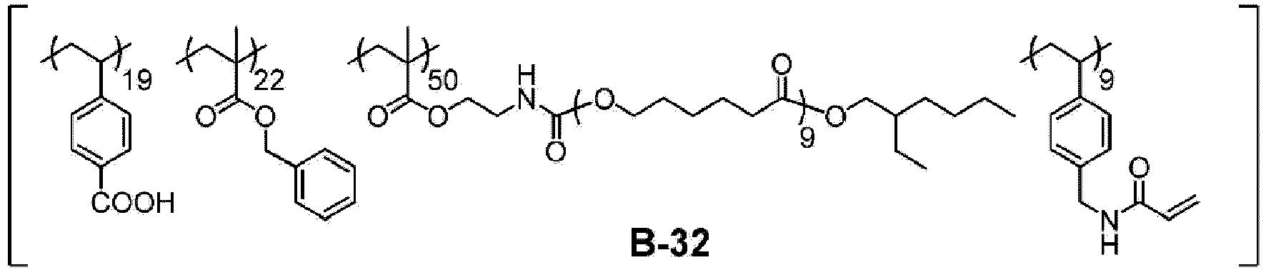
- b-1 having the following structure (weight-average molecular weight: 2.8 × 10⁴, acid value: 70.0 mgKOH/g) was synthesized by the same method except that, in the synthesis of the prepolymer B-5' in Synthesis Example 1, the proportion of the raw materials was changed. In the following structural formula, the numerical value added to the main chain is a mass ratio.

- 94.84 g (0.12 mol) of dipentaerythritol hexakis(3-mercaptopropionate) (DPMP), 55.16 g (0.42 mol) of itaconic acid, and 350.00 g of MFG were charged into a three-neck flask. After purging with nitrogen at room temperature, an oxygen concentration of 1% or less was confirmed, and the mixture was heated to 80°C and stirred (nitrogen flow rate: 50 mL/min, stirring rate: 200 rpm). After temperature stabilization, 0.24 g (1.06 mmol) of
dimethyl 2,2'-azobis(isobutyrate) was added thereto, and the mixture was stirred for 2 hours. Next, 0.24 g (1.06 mmol) ofdimethyl 2,2'-azobis(isobutyrate) was added thereto, and the mixture was heated to 90°C and stirred for 2 hours. The mixture was cooled to room temperature to obtain a 30% by mass solution of an intermediate D-1" (yield amount: 495.90 g). - 549.00 g of propylene glycol monomethyl ether acetate (PGMEA) was charged into a three-neck flask, and after purging with nitrogen at room temperature to set an oxygen concentration to 1% or less, the mixture was heated to 80°C and stirred (nitrogen flow rate: 50 mL/min, stirring rate: 200 rpm).
- 412.49 g (0.1 mol) of the intermediate D-1", 230.21 g (2.67 mol) of methacrylic acid, 1268.29 g (0.4010 mol) of the compound C-2, 937.36 g of PGMEA, and 5.281 g (23.0 mmol) of
dimethyl 2,2'-azobis(isobutyrate) were charged into an Erlenmeyer flask to prepare a solution. The solution in the Erlenmeyer flask was added dropwise to the three-neck flask over 2.5 hours (dropwise addition rate: 2.80 mL/min). Next, 54.90 g of PGMEA for washing was added to the Erlenmeyer flask to wash the inside of the Erlenmeyer flask, and then PGMEA in the Erlenmeyer flask was added dropwise to the three-neck flask, followed by stirring for 2.5 hours. - Next, 5.281 g (23.0 mmol) of
dimethyl 2,2'-azobis(isobutyrate) was added to the three-neck flask, and the mixture was heated to 90°C and stirred for 2 hours (nitrogen flow rate: 50 mL/min, stirring rate: 250 rpm). The mixture was cooled to room temperature to obtaining a 40% by mass solution of a prepolymer D-1' (yield amount: 3300 g, weight-average molecular weight: 1.3 × 10⁴, acid value: 153.1 mgKOH/g). - D-1 having the following structure (weight-average molecular weight: 1.2 × 10⁴, acid value: 155.0 mgKOH/g, C=C value: 0.28 mmol/g) was synthesized by the same method except that, in the synthesis of the resin B-28 in Synthesis Example 28, the prepolymer D-1' was used instead of B-28'.
- Resins D-2 to D-6 having the following structures were respectively synthesized in the same manner as in Synthesis Example 34, except that, in Synthesis Example 34, a proportion of the raw materials was changed. In the following structural formulae, the subscript number is the number of repeating units.

- A compound C-3 was synthesized in the same manner as the compound C-2, except that, in the synthesis of the compound C-2, 6-bromohexanoyl chloride was used instead of 2-bromopropionyl chloride.

- A resin D-7 having the following structure (weight-average molecular weight: 1.4 × 10⁴, acid value: 158.0 mgKOH/g, C=C value: 0.28 mmol/g) was synthesized in the same manner as in Synthesis Example 34, except that, in Synthesis Example 34, the compound C-3 was used instead of the compound C-2. In the following structural formulae, the subscript number is the number of repeating units.

- A resin D-8 having the following structure (weight-average molecular weight: 1.3 × 10⁴, acid value: 158.0 mgKOH/g, C=C value: 0.23 mmol/g) was synthesized in the same manner as in Synthesis Example 34, except that, in Synthesis Example 34, PVBA was used instead of methacrylic acid. In the following structural formulae, the subscript number is the number of repeating units.

- A resin D-9 having the following structure (weight-average molecular weight: 1.2 × 10⁴, acid value: 158.0 mgKOH/g, C=C value: 0.26 mmol/g) was synthesized in the same manner as in Synthesis Example 34, except that, in Synthesis Example 34, NK ESTER CB-1 (manufactured by Shin-Nakamura Chemical Co., Ltd.) was used instead of itaconic acid. In the following structural formulae, the subscript number is the number of repeating units.

- A block polymer was synthesized using a compound which derived each component so that the compound had a formulation (type and content of the constitutional component) shown in the following chemical formula, according to Example 1 described in paragraphs 0101 and 0102 of
JP2011-054439A 
- A resin D-11 having the following structure (weight-average molecular weight: 1.2 × 10⁴, acid value: 158.0 mgKOH/g, C=C value: 0.5 mmol/g) was synthesized in the same manner as in Synthesis Example 30, except that, in Synthesis Example 30, butyl methyl methacrylate was used instead of benzyl methyl methacrylate and methyl methacrylate, and glycidyl methacrylate was used instead of 4HBAGE. In the following structural formula, the numerical value added to the main chain is a mass ratio.

- A resin d-1 having the following structure (weight-average molecular weight: 1.2 × 10⁴, acid value: 158.0 mgKOH/g) was synthesized in the same manner as in Synthesis Example 34, except that, in Synthesis Example 34, methyl methacrylate was used instead of the compound C-2. In the following structural formulae, the subscript number is the number of repeating units.

- A resin d-2 having the following structure (weight-average molecular weight: 1.2 × 10⁴, acid value: 158.0 mgKOH/g) was synthesized in the same manner as in Synthesis Example 33, except that, in Synthesis Example 33, the type of the raw material was changed to methacrylic acid and lauryl methacrylate, and a proportion thereof was changed. In the following structural formula, the numerical value added to the main chain is a mass ratio.

- A resin T-1 having the following structure (weight-average molecular weight: 2.8 × 10⁴, acid value: 70.0 mgKOH/g, C=C value: 0.5 mmol/g) was synthesized in the same manner as in Synthesis Example 33, except that, in Synthesis Example 33, the type of the raw material was changed to methacrylic acid and glycidyl methacrylate, and a proportion thereof was changed. In the following structural formula, the numerical value added to the main chain is a mass ratio.

- The weight-average molecular weights, acid values, and ethylenically unsaturated bond-containing group values (C=C values) of the obtained resins are shown in the following tables.
[Table 1] Type of polymer Weight-average molecular weight Acid value (mgKOH/g) C=C value (mmol/g) B-1 28000 70 0.05 B-2 28000 70 2.1 B-3 28000 70 0.2 B-4 28000 70 1.8 B-5 28000 70 0.5 B-6 9000 70 0.5 B-7 15000 70 0.5 B-8 60000 70 0.5 B-9 100000 70 0.5 B-10 28000 15 0.5 B-11 28000 120 0.5 B-12 28000 70 0.5 B-13 28000 70 0.35 B-14 28000 70 0.5 B-15 28000 70 0.5 B-16 28000 70 0.5 B-17 28000 70 0.5 B-18 28000 70 0.5 B-19 27000 70 0.5 B-20 27000 70 0.5 B-21 28000 70 0.5 B-22 28000 70 0.5 B-23 28000 70 0.5 B-24 28000 70 0.5 B-25 28000 70 0.5 B-26 28000 70 0.5 B-27 28000 70 0.5 B-28 28000 70 0.5 B-29 28000 70 0.5 B-30 28000 70 0.5 B-31 28000 70 0.5 B-32 28000 70 0.5 b-1 28000 70 0.5 T-1 28000 70 0.5 [Table 2] Type of polymer Weight-average molecular weight Acid value (mgKOH/g) C=C value (mmol/g) D-1 12000 155 0.28 D-2 11000 210 0.23 D-3 14000 100 0.35 D-4 4000 158 0.24 D-5 25000 158 0.29 D-6 108000 158 0.3 D-7 14000 158 0.28 D-8 13000 158 0.23 D-9 12000 158 0.26 D-10 12000 158 0.5 D-11 12000 158 0.5 d-1 12000 158 0 d-2 12000 158 0 - By using ULTRA APEX MILL (manufactured by Kotobuki Industries Co., Ltd.) as a circulation type dispersion apparatus (beads mill), a mixed solution having the following composition shown in the following table was dispersed. In this way, a dispersion liquid was produced.
- Bead diameter: diameter 0.2 mm
- Bead filling rate: 65 volume%
- Circumferential speed: 6 m/sec
- Pump supply amount: 10.8 kg/hour
- Cooling water: tap water
- Beads mill circular passage inner volume: 0.15 L
- Amount of mixed solution to be dispersed: 0.65 kg
- The raw materials shown above in the table are as follows.
-
[Table 4] Particles Name (manufacturer) Type Specific gravity [g/cm3] Refractive index Average primary particle diameter [nm] P-1 TTO-51 (manufactured by ISHIHARA SANGYO KAISHA, LTD.) Titanium oxide particles 4.1 2.71 20 P-2 TTO-80A (manufactured by ISHIHARA SANGYO KAISHA, LTD.) Titanium oxide particles 4.1 2.71 60 P-3 MPT-136 (manufactured by ISHIHARA SANGYO KAISHA, LTD.) Titanium oxide particles 4.1 2.71 80 P-4 MPT-141 (manufactured by ISHIHARA SANGYO KAISHA, LTD.) Titanium oxide particles 4.1 2.71 91 P-5 Zirconeo-Cp (manufactured by ITEC Co., Ltd.) Zirconium oxide particles 5.7 2.11 10 P-6 CR-90-2 (manufactured by ISHIHARA SANGYO KAISHA, LTD.) Titanium oxide particles 4.1 2.71 250 P-7 Aluminum oxide nanoparticles (manufactured by EM Japan) Aluminum oxide particles 4.0 1.77 80 - D-1 to D-11, d-1, d-2: resins D-1 to D-11, d-1, and d-2 described above
-
- S-1: propylene glycol monomethyl ether acetate (PGMEA)
- S-2: propylene glycol monomethyl ether (PGME)
- S-3: cyclopentanone
- Raw materials shown in the following tables were mixed with each other to prepare a composition.
[Table 5] Dispersion liquid Resin (binder) Polymerizable monomer Photopolymerization initiator Additive Surfactant Polymerization inhibitor Solvent Type Part by mass Type Part by mass Type Part by mass Type Part by mass Type Part by mass Type Part by mass Type Part by mass Type Part by mass Example 1 Dispersion liquid 1 52 B-5 8.96 M-2 9.58 I-3 2.70 A-1 0.25 Su-1 0.008 In-1 0.005 S-1 24 A-3 2.50 Example 2 Dispersion liquid 2 52 B-5 8.96 M-2 9.58 I-3 2.70 A-1 0.25 Su-1 0.008 In-1 0.005 S-1 24 A-3 2.50 Example 3 Dispersion liquid 3 52 B-5 8.96 M-2 9.58 I-3 2.70 A-1 0.25 Su-1 0.008 In-1 0.005 S-1 24 A-3 2.50 Example 4 Dispersion liquid 4 52 B-5 8.96 M-2 9.58 I-3 2.70 A-1 0.25 Su-1 0.008 In-1 0.005 S-1 24 A-3 2.50 Example 5 Dispersion liquid 5 52 B-5 8.96 M-2 9.58 I-3 2.70 A-1 0.25 Su-1 0.008 In-1 0.005 S-1 24 A-3 2.50 Example 6 Dispersion liquid 8 52 B-5 8.96 M-2 9.58 I-3 2.70 A-1 0.25 Su-1 0.008 In-1 0.005 S-1 24 A-3 2.50 Example 7 Dispersion liquid 4 52 B-5 8.96 M-1 9.58 I-3 2.70 A-1 0.25 Su-1 0.008 In-1 0.005 S-1 24 A-3 2.50 Example 8 Dispersion liquid 4 52 B-5 8.96 M-3 9.58 I-3 2.70 A-1 0.25 Su-1 0.008 In-1 0.005 S-1 24 A-3 2.50 Example 9 Dispersion liquid 4 52 B-5 8.96 M-4 9.58 I-3 2.70 A-1 0.25 Su-1 0.008 In-1 0.005 S-1 24 A-3 2.50 Example 10 Dispersion liquid 4 52 B-5 8.96 M-2 9.58 I-1 2.70 A-1 0.25 Su-1 0.008 In-1 0.005 S-1 24 A-3 2.50 Example 11 Dispersion liquid 4 52 B-5 8.96 M-2 9.58 I-2 2.70 A-1 0.25 Su-1 0.008 In-1 0.005 S-1 24 A-3 2.50 Example 12 Dispersion liquid 4 52 B-5 8.96 M-2 9.58 I-3 2.70 A-2 0.25 Su-1 0.008 In-1 0.005 S-1 24 A-3 2.50 Example 13 Dispersion liquid 4 52 B-5 8.96 M-2 9.58 I-3 2.70 A-1 0.25 Su-1 0.008 In-2 0.005 S-1 24 A-3 2.50 Example 14 Dispersion liquid 4 52 B-5 8.96 M-2 9.58 I-3 2.70 A-1 0.25 Su-1 0.008 In-1 0.005 S-2 24 A-3 2.50 Example 15 Dispersion liquid 4 52 B-5 8.96 M-2 9.58 I-3 2.70 A-1 0.25 Su-1 0.008 In-1 0.005 S-3 24 A-3 2.50 [Table 6] Dispersion liquid Resin (binder) Polymerizable monomer Photopolymerization initiator Additive Surfactant Polymerization inhibitor Solvent Type Part by mass Type Part by mass Type Part by mass Type Part by mass Type Part by mass Type Part by mass Type Part by mass Type Part by mass Example 16 Dispersion liquid 9 52 b-1 8.96 M-2 9.58 I-3 2.70 A-1 0.25 Su-1 0.008 In-1 0.005 S-1 24 A-3 2.50 Example 17 Dispersion liquid 10 52 b-1 8.96 M-2 9.58 I-3 2.70 A-1 0.25 Su-1 0.008 In-1 0.005 S-1 24 A-3 2.50 Example 18 Dispersion liquid 11 52 b-1 8.96 M-2 9.58 I-3 2.70 A-1 0.25 Su-1 0.008 In-1 0.005 S-1 24 A-3 2.50 Example 19 Dispersion liquid 12 52 b-1 8.96 M-2 9.58 I-3 2.70 A-1 0.25 Su-1 0.008 In-1 0.005 S-1 24 A-3 2.50 Example 20 Dispersion liquid 13 52 b-1 8.96 M-2 9.58 I-3 2.70 A-1 0.25 Su-1 0.008 In-1 0.005 S-1 24 A-3 2.50 Example 21 Dispersion liquid 14 52 b-1 8.96 M-2 9.58 I-3 2.70 A-1 0.25 Su-1 0.008 In-1 0.005 S-1 24 A-3 2.50 Example 22 Dispersion liquid 15 52 b-1 8.96 M-2 9.58 I-3 2.70 A-1 0.25 Su-1 0.008 In-1 0.005 S-1 24 A-3 2.50 Example 23 Dispersion liquid 16 52 b-1 8.96 M-2 9.58 I-3 2.70 A-1 0.25 Su-1 0.008 In-1 0.005 S-1 24 A-3 2.50 Example 24 Dispersion liquid 17 52 b-1 8.96 M-2 9.58 I-3 2.70 A-1 0.25 Su-1 0.008 In-1 0.005 S-1 24 A-3 2.50 Example 25 Dispersion liquid 18 52 b-1 8.96 M-2 9.58 I-3 2.70 A-1 0.25 Su-1 0.008 In-1 0.005 S-1 24 A-3 2.50 Example 26 Dispersion liquid 19 52 b-1 8.96 M-2 9.58 I-3 2.70 A-1 0.25 Su-1 0.008 In-1 0.005 S-1 24 A-3 2.50 Example 27 Dispersion liquid 4 52 B-1 8.96 M-2 9.58 I-3 2.70 A-1 0.25 Su-1 0.008 In-1 0.005 S-1 24 A-3 2.50 Example 28 Dispersion liquid 4 52 B-2 8.96 M-2 9.58 I-3 2.70 A-1 0.25 Su-1 0.008 In-1 0.005 S-1 24 A-3 2.50 Example 29 Dispersion liquid 4 52 B-3 8.96 M-2 9.58 I-3 2.70 A-1 0.25 Su-1 0.008 In-1 0.005 S-1 24 A-3 2.50 Example 30 Dispersion liquid 4 52 B-4 8.96 M-2 9.58 I-3 2.70 A-1 0.25 Su-1 0.008 In-1 0.005 S-1 24 A-3 2.50 [Table 7] Dispersion liquid Resin (binder) Polymerizable monomer Photopolymerization initiator Additive Surfactant Polymerization inhibitor Solvent Type Part by mass Type Part by mass Type Part by mass Type Part by mass Type Part by mass Type Part by mass Type Part by mass Type Part by mass Example 31 Dispersion liquid 4 52 B-6 8.96 M-2 9.58 I-3 2.70 A-1 0.25 Su-1 0.008 In-1 0.005 S-1 24 A-3 2.50 Example 32 Dispersion liquid 4 52 B-7 8.96 M-2 9.58 I-3 2.70 A-1 0.25 Su-1 0.008 In-1 0.005 S-1 24 A-3 2.50 Example 33 Dispersion liquid 4 52 B-8 8.96 M-2 9.58 I-3 2.70 A-1 0.25 Su-1 0.008 In-1 0.005 S-1 24 A-3 2.50 Example 34 Dispersion liquid 4 52 B-9 8.96 M-2 9.58 I-3 2.70 A-1 0.25 Su-1 0.008 In-1 0.005 S-1 24 A-3 2.50 Example 35 Dispersion liquid 4 52 B-10 8.96 M-2 9.58 I-3 2.70 A-1 0.25 Su-1 0.008 In-1 0.005 S-1 24 A-3 2.50 Example 36 Dispersion liquid 4 52 B-11 8.96 M-2 9.58 I-3 2.70 A-1 0.25 Su-1 0.008 In-1 0.005 S-1 24 A-3 2.50 Example 37 Dispersion liquid 4 52 B-12 8.96 M-2 9.58 I-3 2.70 A-1 0.25 Su-1 0.008 In-1 0.005 S-1 24 A-3 2.50 Example 38 Dispersion liquid 4 52 B-13 8.96 M-2 9.58 I-3 2.70 A-1 0.25 Su-1 0.008 In-1 0.005 S-1 24 A-3 2.50 Example 39 Dispersion liquid 4 52 B-14 8.96 M-2 9.58 I-3 2.70 A-1 0.25 Su-1 0.008 In-1 0.005 S-1 24 A-3 2.50 Example 40 Dispersion liquid 4 52 B-15 8.96 M-2 9.58 I-3 2.70 A-1 0.25 Su-1 0.008 In-1 0.005 S-1 24 A-3 2.50 Example 41 Dispersion liquid 4 52 B-16 8.96 M-2 9.58 I-3 2.70 A-1 0.25 Su-1 0.008 In-1 0.005 S-1 24 A-3 2.50 Example 42 Dispersion liquid 4 52 B-17 8.96 M-2 9.58 I-3 2.70 A-1 0.25 Su-1 0.008 In-1 0.005 S-1 24 A-3 2.50 Example 43 Dispersion liquid 4 52 B-18 8.96 M-2 9.58 I-3 2.70 A-1 0.25 Su-1 0.008 In-1 0.005 S-1 24 A-3 2.50 Example 44 Dispersion liquid 4 52 B-19 8.96 M-2 9.58 I-3 2.70 A-1 0.25 Su-1 0.008 In-1 0.005 S-1 24 A-3 2.50 Example 45 Dispersion liquid 4 52 B-20 8.96 M-2 9.58 I-3 2.70 A-1 0.25 Su-1 0.008 In-1 0.005 S-1 24 A-3 2.50 [Table 8] Dispersion liquid Resin (binder) Polymerizable monomer Photopolymerization initiator Additive Surfactant Polymerization inhibitor Solvent Type Part by mass Type Part by mass Type Part by mass Type Part by mass Type Part by mass Type Part by mass Type Part by mass Type Part by mass Example 46 Dispersion liquid 4 52 B-21 8.96 M-2 9.58 I-3 2.70 A-1 0.25 Su-1 0.008 In-1 0.005 S-1 24 A-3 2.50 Example 47 Dispersion liquid 4 52 B-22 8.96 M-2 9.58 1-3 2.70 A-1 0.25 Su-1 0.008 In-1 0.005 S-1 24 A-3 2.50 Example 48 Dispersion liquid 4 52 B-23 8.96 M-2 9.58 I-3 2.70 A-1 0.25 Su-1 0.008 In-1 0.005 S-1 24 A-3 2.50 Example 49 Dispersion liquid 4 52 B-24 8.96 M-2 9.58 I-3 2.70 A-1 0.25 Su-1 0.008 In-1 0.005 S-1 24 A-3 2.50 Example 50 Dispersion liquid 4 52 B-25 8.96 M-2 9.58 I-3 2.70 A-1 0.25 Su-1 0.008 In-1 0.005 S-1 24 A-3 2.50 Example 51 Dispersion liquid 4 52 B-26 8.96 M-2 9.58 I-3 2.70 A-1 0.25 Su-1 0.008 In-1 0.005 S-1 24 A-3 2.50 Example 52 Dispersion liquid 4 52 B-27 8.96 M-2 9.58 I-3 2.70 A-1 0.25 Su-1 0.008 In-1 0.005 S-1 24 A-3 2.50 Example 53 Dispersion liquid 4 52 B-28 8.96 M-2 9.58 I-3 2.70 A-1 0.25 Su-1 0.008 In-1 0.005 S-1 24 A-3 2.50 Example 54 Dispersion liquid 4 52 B-29 8.96 M-2 9.58 I-3 2.70 A-1 0.25 Su-1 0.008 In-1 0.005 S-1 24 A-3 2.50 Example 55 Dispersion liquid 4 52 B-30 8.96 M-2 9.58 I-3 2.70 A-1 0.25 Su-1 0.008 In-1 0.005 S-1 24 A-3 2.50 Example 56 Dispersion liquid 4 52 B-31 8.96 M-2 9.58 I-3 2.70 A-1 0.25 Su-1 0.008 In-1 0.005 S-1 24 A-3 2.50 Example 57 Dispersion liquid 20 52 B-5 8.96 M-2 9.58 I-3 2.70 A-1 0.25 Su-1 0.008 In-1 0.005 S-1 24 A-3 2.50 Example 58 Dispersion liquid 21 52 B-5 8.96 M-2 9.58 1-3 2.70 A-1 0.25 Su-1 0.008 In-1 0.005 S-1 24 A-3 2.50 Example 59 Dispersion liquid 22 52 B-5 8.96 M-2 9.58 1-3 2.70 A-1 0.25 Su-1 0.008 In-1 0.005 S-1 24 A-3 2.50 Example 60 Dispersion liquid 9 52 B-5 8.96 M-2 9.58 1-3 2.70 A-1 0.25 Su-1 0.008 In-1 0.005 S-1 24 A-3 2.50 [Table 9] Dispersion liquid Resin (binder) Polymerizable monomer Photopolymerization initiator Additive Surfactant Polymerization inhibitor Solvent Type Part by mass Type Part by mass Type Part by mass Type Part by mass Type Part by mass Type Part by mass Type Part by mass Type Part by mass Example 61 Dispersion liquid 4 60 B-5 8.96 M-2 5.58 I-3 2.70 A-1 0.25 Su-1 0.008 In-1 0.005 S-1 20 A-3 2.50 Example 62 Dispersion liquid 4 52 B-5 15.96 M-2 7.58 I-3 2.70 A-1 0.25 Su-1 0.008 In-1 0.005 S-1 19 A-3 2.50 Example 63 Dispersion liquid 4 55 B-5 10.96 M-2 7.58 I-3 2.70 A-1 0.25 Su-1 0.008 In-1 0.005 S-1 21 A-3 2.50 Example 64 Dispersion liquid 4 48 B-5 8.96 M-2 11.58 I-3 2.70 A-1 0.25 Su-1 0.008 In-1 0.005 S-1 26 A-3 2.50 Example 65 Dispersion liquid 4 52 B-5 5.96 M-2 10.58 I-3 2.70 A-1 0.25 Su-1 0.008 In-1 0.005 S-1 26 A-3 2.50 Example 66 Dispersion liquid 4 48 B-5 5.96 M-2 12.58 I-3 2.70 A-1 0.25 Su-1 0.008 In-1 0.005 S-1 28 A-3 2.50 Example 67 Dispersion liquid 4 52 B-5 8.96 M-2 9.58 1-4 2.70 A-1 0.25 Su-1 0.008 In-1 0.005 S-1 24 A-3 2.50 Example 68 Dispersion liquid 4 52 B-5 8.96 M-2 9.58 I-3 2.70 A-1 0.25 Su-2 0.008 In-1 0.005 S-1 24 A-3 2.50 Example 69 Dispersion liquid 4 52 B-32 8.96 M-2 9.58 I-3 2.70 A-1 0.25 Su-1 0.008 In-1 0.005 S-1 24 A-3 2.50 Example 70 Dispersion liquid 4 52 B-5 8.96 M-2 9.58 I-3 2.56 A-1 0.25 Su-1 0.008 In-1 0.005 S-1 24 1-4 0.14 A-3 2.50 Comparative Example 1 Dispersion liquid 20 52 T-1 8.96 M-2 9.58 I-3 2.70 A-1 0.25 Su-1 0.008 In-1 0.005 S-1 24 A-3 2.50 Comparative Example 2 Dispersion liquid 6 52 T-1 8.96 M-2 9.58 I-3 2.70 A-1 0.25 Su-1 0.008 In-1 0.005 S-1 24 A-3 2.50 Comparative Example 3 Dispersion liquid 7 52 T-1 8.96 M-2 9.58 I-3 2.70 A-1 0.25 Su-1 0.008 In-1 0.005 S-1 24 A-3 2.50 - The raw materials shown above in the table are as follows.
-
Dispersion liquids 1 to 22:dispersion liquids 1 to 22 described above - B-1 to B-32, b-1, T-1: resins B-1 to B-32, b-1, and T-1 described above
-
- M-1: KAYARAD DPHA (manufactured by Nippon Kayaku Co., Ltd., dipentaerythritol hexa(meth)acrylate)
- M-2: KAYARAD RP-1040 (manufactured by Nippon Kayaku Co., Ltd., compound having the following structure)

- M-3: NK ESTER A-TMMT (manufactured by Shin-Nakamura Chemical Co., Ltd.)
- M-4: Light Acrylate DCP-A (manufactured by KYOEISHA CHEMICAL Co., Ltd., dimethyloltricyclodecane diacrylate)
-
- 1-1: Irgacure OXE01 (manufactured by BASF)
- 1-2: Omnirad 369 (manufactured by IGM Resins B.V)
- 1-3: Omnirad TPO H (manufactured by IGM Resins B.V.)
- 1-4: Irgacure OXE03 (manufactured by BASF)
-
- A-1: ADEKA STAB AO-80 (manufactured by Adeka Corporation, anti-coloring agent)
- A-2: Irganox 1010 (manufactured by BASF, anti-coloring agent)
- A-3: compound having the following structure (silane coupling agent)
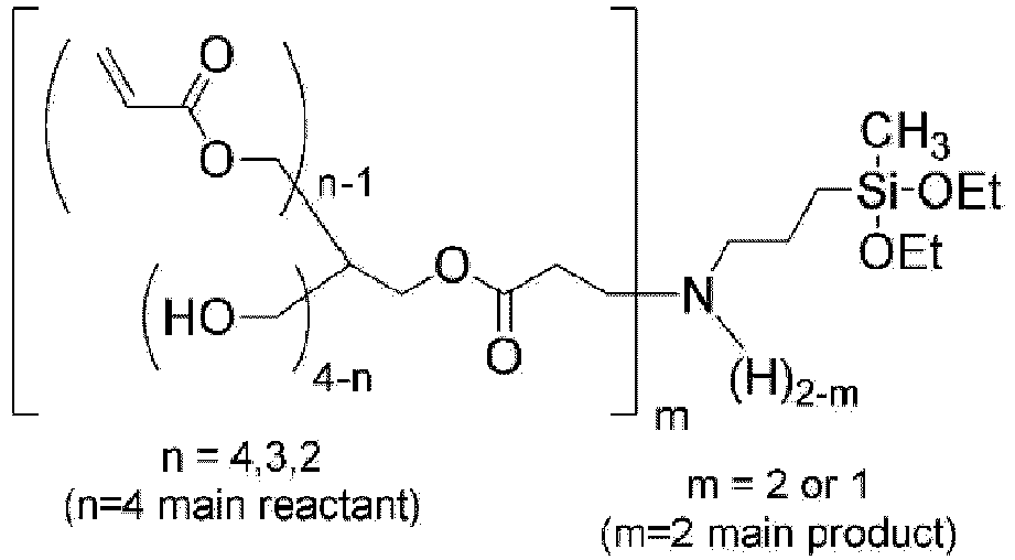
-
- Su-1: KF-6001 (manufactured by Shin-Etsu Chemical Co., Ltd.; silicone-based surfactant having the following structure)

- Su-2: SH8400 (manufactured by Dow TORAY; silicone-based surfactant)
-
- In-1: p-methoxyphenol
- In-2: 1,4-benzoquinone
-
- S-1: propylene glycol monomethyl ether acetate (PGMEA)
- S-2: propylene glycol monomethyl ether (PGME)
- S-3: cyclopentanone
- Each of the compositions was applied to an 8-inch (= 203.2 mm) glass wafer with an undercoat layer (manufactured by Fujifilm Electronic Materials Co., Ltd., CT-4000L, thickness: 0.1 µm) using a spin coater such that the thickness after post-baking was 8 µm. The coating film was heat-treated (pre-baked) using a hot plate at 120°C for 2 minutes.
- Next, using an i-ray stepper exposure device FPA-3000 i5+ (manufactured by Canon Inc.), the coating film was exposed by irradiating the coating film with light having a wavelength of 365 nm through a mask with a 300 µm square opening portion at an exposure amount of 1700 mJ/cm2. The glass wafer with the film after exposure was placed on a horizontal rotary table of a spin-shower developing machine (DW-30 Type, manufactured by Chemitronics Co., Ltd.), and subjected to a puddle development at 23°C for 60 seconds using an alkali developer (CD-2060, manufactured by Fujifilm Electronic Materials Co., Ltd.). Next, the glass wafer after the puddle development was fixed on the horizontal rotary table by a vacuum chuck method, a rinse treatment (23 seconds × 2 times) was performed by supplying pure water from above a rotation center in shower-like from an ejection nozzle while rotating the glass wafer at a rotation speed of 50 rpm by a rotating device, and then the glass wafer was spin-dried. Next, a heating treatment (post-baking) was performed for 5 minutes using a hot plate at 220°C to form a colored pattern (pattern size: 300 µm).
- The obtained pattern was evaluated for undercut and tape peeling resistance to evaluate curing properties.
- The pattern (film) formed on the glass wafer was imaged with an optical microscope, and a region where the pattern (film) was in close contact with the glass wafer was specified from a shade of color to calculate an area S2 of the region where the pattern (film) was in close contact with the glass wafer.
- An area ratio Y (= S2/S1) of the area S2 of the region where the pattern was in close contact with the glass wafer to an area S1 (= 300 µm × 300 µm) of the pattern was calculated, and an average value × of undercut lengths was calculated by the following expression.

-
- 5: average value of undercut lengths was less than 5 µm.
- 4: average value of undercut lengths was 5 µm or more and less than 10 µm.
- 3: average value of undercut lengths was 10 µm or more and less than 15 µm.
- 2: average value of undercut lengths was 15 µm or more and less than 20 µm.
- 1: average value of undercut lengths was 20 µm or more.
- An ultraviolet curable tape (D-510TT, manufactured by LINTEC Corporation) was attached to a surface of the pattern formed on the glass wafer, the ultraviolet curable tape was cured by irradiation with light at an exposure amount of 1000 mJ/cm2 using an exposure machine (Portable Cure 100, manufactured by SEN LIGHTS Co., Ltd.), and then the tape was peeled off from the surface of the pattern to perform tape peeling resistance.
- A pattern peeling rate was calculated from the number of patterns on the glass wafer before and after the tape peeling resistance test, and the tape peeling resistance was evaluated based on the following standard.

- A1: number of patterns formed on the glass wafer before the tape peeling resistance test
- A2: number of patterns formed on the glass wafer after the tape peeling resistance test
-
- 5: pattern peeling rate was less than 10%.
- 4: pattern peeling rate was 10% or more and less than 20%.
- 3: pattern peeling rate was 20% or more and less than 30%.
- 2: pattern peeling rate was 30% or more and less than 40%.
- 1: pattern peeling rate was 40% or more.
- Each of the compositions was applied to an 8-inch (= 203.2 mm) glass wafer with an undercoat layer (manufactured by Fujifilm Electronic Materials Co., Ltd., CT-4000L, thickness: 0.1 µm) using a spin coater such that the thickness after post-baking was 8 µm. The coating film was heat-treated (pre-baked) using a hot plate at 120°C for 2 minutes. Next, using an i-ray stepper exposure device FPA-3000 i5+ (manufactured by Canon Corporation), the coating film was exposed to light having a wavelength of 365 nm at an exposure amount of 1000 mJ/cm2. Thereafter, a heating treatment (post-baking) was performed for 5 minutes used a hot plate at 220°C to form a film having a thickness of 8 µm.
- A transmittance of the obtained film to light in a wavelength range of 400 to 1000 nm was measured using a spectrophotometer (U-4100, manufactured by manufactured by Hitachi High-Tech Corporation), and the maximum value (Tmax) of the transmittance in the range and an absolute value (transmittance difference ΔT) of a difference between a transmittance (T940) to light having a wavelength of 940 nm and a transmittance (T450) to light having a wavelength of 450 nm were calculated.

-
- 5: transmittance difference ΔT was less than 15%.
- 4: transmittance difference ΔT was 15% or more and less than 25%.
- 3: transmittance difference ΔT was 25% or more and less than 30%.
- 2: transmittance difference ΔT was 30% or more and less than 35%.
- 1: transmittance difference ΔT was 35% or more.
-
- 5: maximum value Tmax of the transmittance was 60% or less.
- 4: maximum value Tmax of the transmittance was more than 60% and 70% or less.
- 3: maximum value Tmax of the transmittance was more than 70% and 75% or less.
- 2: maximum value Tmax of the transmittance was more than 75% and 80% or less.
- 1: maximum value Tmax of the transmittance was more than 80%.
- The film produced above was heated at 265°C for 5 minutes. The transmittance of the film after heating was measured, the maximum value of variation of transmittance was determined, and then the heat resistance was evaluated based on the following standard. In addition, the measurement of transmittance was performed 5 times for each sample, and the average value of the 3 times result except the maximum value and the minimum value was adopted. In addition, the maximum value of the variation of transmittance means a variation of transmittance of the film in a wavelength which has the largest variation of transmittance in a range of 400 to 1000 nm before and after heating.
-
- 5: maximum value of variation of transmittance was 1% or less.
- 4: maximum value of variation of transmittance was more than 1% and 2% or less.
- 3: maximum value of variation of transmittance was more than 2% and 4% or less.
- 2: maximum value of variation of transmittance was more than 4% and 5% or less.
- 1: maximum value of variation of transmittance was more than 5%.
- As shown in the above tables, the compositions of Examples were evaluated as good in undercut and tape peeling resistance, and were excellent in curing properties. In addition, the films formed of the compositions of Examples had excellent light scattering properties. In addition, the films formed of the compositions of Examples also had excellent heat resistance.
- Each of the compositions of Examples 1 to 70 was applied to an 8-inch (= 203.2 mm) glass wafer with an undercoat layer (manufactured by Fujifilm Electronic Materials Co., Ltd., CT-4000L, thickness: 0.1 µm) using a spin coater such that the thickness after post-baking was 8 µm. The coating film was heat-treated (pre-baked) using a hot plate at 120°C for 2 minutes. Next, using an i-ray stepper exposure device FPA-3000 i5+ (manufactured by Canon Corporation), the coating film was exposed to light having a wavelength of 365 nm at an exposure amount of 1000 mJ/cm2. Thereafter, a heating treatment (post-baking) was performed for 5 minutes used a hot plate at 220°C to form a film having a thickness of 8 µm. Using a scanning electron microscope (SEM) (S-4800H, manufactured by Hitachi High-Tech Corporation), a cross section of the obtained film in a thickness direction was observed (magnification: 10000 times), and the uneven distribution state of the particles was confirmed to check whether a phase-separated state was formed.
- In all of the obtained films, the phase-separated structure including the first phase containing particles and the second phase having a lower content of the particles than the first phase was formed in the film.
-
- 1, 2: optical sensor
- 101: photoelectric conversion element
- 111 to 114: pixels
- 110: optical filter
- 121, 122: film
- 130: transparent support
| Particles | Resin (dispersant) | Solvent | ||||
| Type | Part by mass | Type | Part by mass | Type | Part by mass | |
| Dispersion liquid 1 | P-1 | 38.4 | d-1 | 11.6 | S-1 | 50.0 |
| Dispersion liquid 2 | P-2 | 38.4 | d-1 | 11.6 | S-1 | 50.0 |
| Dispersion liquid 3 | P-3 | 38.4 | d-1 | 11.6 | S-1 | 50.0 |
| Dispersion liquid 4 | P-4 | 38.4 | d-1 | 11.6 | S-1 | 50.0 |
| Dispersion liquid 5 | P-5 | 38.4 | d-1 | 11.6 | S-1 | 50.0 |
| Dispersion liquid 6 | P-6 | 38.4 | d-1 | 11.6 | S-1 | 50.0 |
| Dispersion liquid 7 | P-7 | 38.4 | d-1 | 11.6 | S-1 | 50.0 |
| Dispersion liquid 8 | P-3 | 19.2 | d-1 | 11.6 | S-1 | 50.0 |
| P-4 | 19.2 | |||||
| Dispersion liquid 9 | P-4 | 38.4 | D-1 | 11.6 | S-1 | 50.0 |
| Dispersion liquid 10 | P-4 | 38.4 | D-2 | 11.6 | S-1 | 50.0 |
| Dispersion liquid 11 | P-4 | 38.4 | D-3 | 11.6 | S-1 | 50.0 |
| Dispersion liquid 12 | P-4 | 38.4 | D-4 | 11.6 | S-1 | 50.0 |
| Dispersion liquid 13 | P-4 | 38.4 | D-5 | 11.6 | S-1 | 50.0 |
| Dispersion liquid 14 | P-4 | 38.4 | D-6 | 11.6 | S-1 | 50.0 |
| Dispersion liquid 15 | P-4 | 38.4 | D-7 | 11.6 | S-1 | 50.0 |
| Dispersion liquid 16 | P-4 | 38.4 | D-8 | 11.6 | S-1 | 50.0 |
| Dispersion liquid 17 | P-4 | 38.4 | D-9 | 11.6 | S-1 | 50.0 |
| Dispersion liquid 18 | P-4 | 38.4 | D-10 | 11.6 | S-1 | 50.0 |
| Dispersion liquid 19 | P-4 | 38.4 | D-11 | 11.6 | S-1 | 50.0 |
| Dispersion liquid 20 | P-4 | 38.4 | d-2 | 11.6 | S-1 | 50.0 |
| Dispersion liquid 21 | P-1 | 38.4 | d-1 | 11.6 | S-2 | 50.0 |
| Dispersion liquid 22 | P-1 | 38.4 | d-1 | 11.6 | S-3 | 50.0 |
| Curing properties | Light scattering properties | Heat resistance | |||
| Undercut | Tape peeling resistance | Maximum value of transmittance Tmax | Transmittance difference ΔT | ||
| Example 1 | 3 | 3 | 3 | 3 | 4 |
| Example 2 | 4 | 4 | 5 | 5 | 4 |
| Example 3 | 4 | 4 | 5 | 5 | 4 |
| Example 4 | 4 | 4 | 5 | 5 | 4 |
| Example 5 | 3 | 3 | 2 | 2 | 4 |
| Example 6 | 4 | 4 | 5 | 5 | 4 |
| Example 7 | 4 | 4 | 5 | 5 | 4 |
| Example 8 | 4 | 4 | 5 | 5 | 4 |
| Example 9 | 3 | 3 | 5 | 5 | 4 |
| Example 10 | 4 | 4 | 5 | 5 | 4 |
| Example 11 | 4 | 4 | 5 | 5 | 4 |
| Example 12 | 4 | 4 | 5 | 5 | 4 |
| Example 13 | 4 | 4 | 5 | 5 | 4 |
| Example 14 | 4 | 4 | 5 | 5 | 4 |
| Example 15 | 4 | 4 | 5 | 5 | 4 |
| Example 16 | 4 | 4 | 5 | 5 | 4 |
| Example 17 | 3 | 4 | 4 | 4 | 4 |
| Example 18 | 5 | 5 | 4 | 4 | 4 |
| Example 19 | 3 | 3 | 4 | 4 | 4 |
| Example 20 | 4 | 4 | 5 | 5 | 4 |
| Example 21 | 4 | 4 | 4 | 4 | 4 |
| Example 22 | 2 | 2 | 5 | 5 | 4 |
| Example 23 | 4 | 4 | 5 | 5 | 5 |
| Example 24 | 4 | 4 | 5 | 5 | 4 |
| Example 25 | 4 | 4 | 2 | 2 | 4 |
| Example 26 | 4 | 4 | 2 | 2 | 4 |
| Example 27 | 3 | 3 | 5 | 5 | 4 |
| Example 28 | 4 | 3 | 5 | 5 | 3 |
| Example 29 | 4 | 4 | 5 | 5 | 4 |
| Example 30 | 4 | 4 | 5 | 5 | 4 |
| Example 31 | 3 | 3 | 4 | 4 | 4 |
| Example 32 | 4 | 4 | 5 | 5 | 4 |
| Example 33 | 4 | 4 | 5 | 5 | 4 |
| Example 34 | 4 | 4 | 4 | 4 | 4 |
| Example 35 | 5 | 5 | 3 | 3 | 4 |
| Curing properties | Light scattering properties | Heat resistance | |||
| Undercut | Tape peeling resistance | Maximum value of transmittance Tmax | Transmittance difference ΔT | ||
| Example 36 | 3 | 3 | 4 | 4 | 4 |
| Example 37 | 3 | 3 | 5 | 5 | 4 |
| Example 38 | 4 | 4 | 5 | 5 | 4 |
| Example 39 | 4 | 4 | 5 | 5 | 4 |
| Example 40 | 4 | 4 | 5 | 5 | 4 |
| Example 41 | 4 | 4 | 5 | 5 | 4 |
| Example 42 | 4 | 4 | 5 | 5 | 4 |
| Example 43 | 4 | 4 | 5 | 5 | 4 |
| Example 44 | 4 | 4 | 5 | 5 | 4 |
| Example 45 | 3 | 3 | 5 | 5 | 4 |
| Example 46 | 2 | 2 | 5 | 5 | 4 |
| Example 47 | 2 | 3 | 5 | 5 | 4 |
| Example 48 | 2 | 3 | 5 | 5 | 4 |
| Example 49 | 2 | 3 | 5 | 5 | 4 |
| Example 50 | 2 | 3 | 5 | 5 | 4 |
| Example 51 | 5 | 5 | 5 | 5 | 4 |
| Example 52 | 4 | 4 | 5 | 5 | 4 |
| Example 53 | 4 | 4 | 5 | 5 | 4 |
| Example 54 | 3 | 3 | 4 | 4 | 3 |
| Example 55 | 4 | 4 | 3 | 3 | 4 |
| Example 56 | 4 | 4 | 4 | 4 | 4 |
| Example 57 | 4 | 4 | 2 | 2 | 4 |
| Example 58 | 4 | 4 | 5 | 5 | 4 |
| Example 59 | 4 | 4 | 5 | 5 | 4 |
| Example 60 | 5 | 5 | 5 | 5 | 5 |
| Example 61 | 3 | 3 | 4 | 4 | 4 |
| Example 62 | 4 | 4 | 3 | 3 | 4 |
| Example 63 | 4 | 4 | 5 | 5 | 4 |
| Example 64 | 4 | 4 | 2 | 2 | 4 |
| Example 65 | 4 | 4 | 4 | 4 | 4 |
| Example 66 | 4 | 4 | 3 | 3 | 4 |
| Example 67 | 4 | 4 | 5 | 5 | 4 |
| Example 68 | 4 | 4 | 5 | 5 | 4 |
| Example 69 | 2 | 3 | 5 | 5 | 4 |
| Example 70 | 4 | 4 | 5 | 5 | 4 |
| Comparative Example 1 | 1 | 1 | 2 | 2 | 1 |
| Comparative Example 2 | 1 | 1 | 1 | 1 | 1 |
| Comparative Example 3 | 1 | 1 | 1 | 1 | 1 |
Claims (17)
- A composition comprising:particles having a refractive index of 2.0 or more and an average primary particle diameter of 200 nm or less;a film-forming component; anda solvent,wherein the film-forming component includes two or more kinds of resins, or includes one or more kinds of resins and one or more kinds of polymerizable monomers, andat least one kind of the resins includes a resin a having a partial structure represented by Formula (1),
 in Formula (1), Ar1 represents an aromatic ring, L1 represents a single bond or an (r+1)-valent linking group, R1 represents an ethylenically unsaturated bond-containing group, R10 represents a substituent, * represents a bonding site, n represents 1 or 2, m represents 0 or an integer of 1 or more, and r represents an integer of 1 or more,provided that in a case where m is 2 or more, m pieces of R10's may be the same or different from each other, andin a case where r is 2 or more, r pieces of R1's may be the same or different from each other.
 - The composition according to claim 1,
wherein an ethylenically unsaturated bond-containing group value of the resin a is 0.1 to 2.0 mmol/g. - The composition according to claim 1 or 2,wherein the film-forming component includes a resin as a dispersant of the particles and a resin as a binder, andat least one selected from the resin as a dispersant of the particles or the resin as a binder is the resin a.
- The composition according to claim 3,
wherein the film-forming component includes 40 to 250 parts by mass of the resin as a binder with respect to 100 parts by mass of the resin as a dispersant of the particles. - The composition according to claim 1 or 2,wherein the film-forming component includes a resin having a structure in which a plurality of polymer chains are bonded to a tri- or higher valent linking group and a resin having a repeating unit having a graft chain, andat least one selected from the resin having a structure in which a plurality of polymer chains are bonded to a tri- or higher valent linking group or the resin having a repeating unit having a graft chain is the resin a.
- The composition according to claim 5,
wherein the graft chain includes a polyester structural repeating unit. - The composition according to claim 1 or 2,wherein the resin a is a resin including at least one repeating unit selected from a repeating unit represented by Formula (1-1) or a repeating unit represented by Formula (1-2),
 in the formulae, L1 represents a single bond or an (r+1)-valent linking group,R1 represents an ethylenically unsaturated bond-containing group,R2 and R3 each independently represent a hydrogen atom or an alkyl group,L11 represents a single bond or a divalent linking group, andr represents an integer of 1 or more,provided that in a case where r is 2 or more, r pieces of R1's may be the same or different from each other.
 - The composition according to claim 1 or 2,
wherein a weight-average molecular weight of the resin a is 8,000 to 120,000. - The composition according to claim 1 or 2,
wherein an acid value of the resin a is 20 to 200 mgKOH/g. - The composition according to claim 1 or 2,
wherein, in a case where a film having a thickness of 8 µm is formed by heating the composition at 200°C for 5 minutes, a phase-separated structure of a first phase containing the particles and a second phase having a lower content of the particles than the first phase is formed in the film. - The composition according to claim 10,
wherein the phase-separated structure is a sea-island structure or a co-continuous phase structure. - The composition according to claim 1 or 2,
wherein the average primary particle diameter of the particles is 100 nm or less. - The composition according to claim 1 or 2,
wherein the particles are inorganic particles. - The composition according to claim 13,
wherein the inorganic particles include at least one selected from titanium oxide particles, strontium titanate particles, barium titanate particles, zinc oxide particles, magnesium oxide particles, zirconium oxide particles, aluminum oxide particles, aluminum hydroxide particles, barium sulfate particles, or zinc sulfide particles. - A resin comprising:at least one repeating unit selected from a repeating unit represented by Formula (1-1) or a repeating unit represented by Formula (1-2),
 in the formulae, L1 represents a single bond or an (r+1)-valent linking group,R1 represents an ethylenically unsaturated bond-containing group,R2 and R3 each independently represent a hydrogen atom or an alkyl group,L11 represents a single bond or a divalent linking group, andr represents an integer of 1 or more,provided that in a case where r is 2 or more, r pieces of R1's may be the same or different from each other.
 - A film formed of the composition according to claim 1 or 2.
- An optical sensor comprising:
the film according to claim 16.
Applications Claiming Priority (2)
| Application Number | Priority Date | Filing Date | Title |
|---|---|---|---|
| JP2021159034 | 2021-09-29 | ||
| PCT/JP2022/035284 WO2023054142A1 (en) | 2021-09-29 | 2022-09-22 | Composition, resin, film and optical sensor |
Publications (2)
| Publication Number | Publication Date |
|---|---|
| EP4410855A1 true EP4410855A1 (en) | 2024-08-07 |
| EP4410855A4 EP4410855A4 (en) | 2024-12-18 |
Family
ID=85780689
Family Applications (1)
| Application Number | Title | Priority Date | Filing Date |
|---|---|---|---|
| EP22876009.6A Pending EP4410855A4 (en) | 2021-09-29 | 2022-09-22 | COMPOSITION, RESIN, FILM AND OPTICAL SENSOR |
Country Status (5)
| Country | Link |
|---|---|
| EP (1) | EP4410855A4 (en) |
| JP (1) | JPWO2023054142A1 (en) |
| CN (1) | CN117916279A (en) |
| TW (1) | TW202319783A (en) |
| WO (1) | WO2023054142A1 (en) |
Family Cites Families (110)
| Publication number | Priority date | Publication date | Assignee | Title |
|---|---|---|---|---|
| JP2515010B2 (en) * | 1989-01-26 | 1996-07-10 | 株式会社メニコン | Ophthalmic lens material |
| SG77689A1 (en) | 1998-06-26 | 2001-01-16 | Ciba Sc Holding Ag | New o-acyloxime photoinitiators |
| DK199901098A (en) | 1998-08-18 | 2000-02-19 | Ciba Sc Holding Ag | Sylphony oxymers for in-line photoresists with high sensitivity and high resistance thickness |
| NL1016815C2 (en) | 1999-12-15 | 2002-05-14 | Ciba Sc Holding Ag | Oximester photo initiators. |
| EP1395615B1 (en) | 2001-06-11 | 2009-10-21 | Basf Se | Oxime ester photoinitiators having a combined structure |
| JP2003261827A (en) | 2002-03-07 | 2003-09-19 | Sekisui Chem Co Ltd | Colored resin emulsion, ink for inkjet printing and color filter |
| JP4305608B2 (en) | 2002-03-11 | 2009-07-29 | Jsr株式会社 | Color filter protective film composition and protective film |
| JP2003185831A (en) | 2002-11-14 | 2003-07-03 | Seiko Epson Corp | Color filter and its manufacturing method, liquid crystal device and its manufacturing method, and electronic equipment |
| JP2006169325A (en) | 2004-12-14 | 2006-06-29 | Sony Corp | Inkjet recording liquid, ink cartridge, and inkjet recording method |
| WO2007060884A1 (en) | 2005-11-25 | 2007-05-31 | Catalysts & Chemicals Industries Co., Ltd. | Hollow silica microparticle, composition for transparent coating formation containing the same, and substrate with transparent coating |
| JP4223071B2 (en) | 2006-12-27 | 2009-02-12 | 株式会社Adeka | Oxime ester compound and photopolymerization initiator containing the compound |
| JP5535065B2 (en) | 2007-05-11 | 2014-07-02 | ビーエーエスエフ ソシエタス・ヨーロピア | Oxime ester photoinitiator |
| US20100203445A1 (en) | 2007-09-26 | 2010-08-12 | Fujifilm Corporation | Negative resist composition and resist pattern forming method using the same |
| JP2009145395A (en) | 2007-12-11 | 2009-07-02 | Tokyo Ohka Kogyo Co Ltd | Pre-wetting agent and resist protective film forming method using the pre-wetting agent |
| JP5147499B2 (en) | 2008-02-13 | 2013-02-20 | 富士フイルム株式会社 | Photosensitive coloring composition, color filter and method for producing the same |
| JP5344843B2 (en) | 2008-03-31 | 2013-11-20 | 富士フイルム株式会社 | Polymerizable composition and solid-state imaging device |
| JP5339781B2 (en) | 2008-05-30 | 2013-11-13 | 富士フイルム株式会社 | Colored curable composition, color filter, and solid-state imaging device |
| CN102112497B (en) | 2008-06-06 | 2013-04-10 | 巴斯夫欧洲公司 | Photoinitiator mixtures |
| JP5371313B2 (en) | 2008-07-28 | 2013-12-18 | 富士フイルム株式会社 | Colored curable composition for color filter, color filter, method for producing color filter, and liquid crystal display element |
| JP2010054632A (en) | 2008-08-26 | 2010-03-11 | Fujifilm Corp | Negative resist composition and pattern forming method |
| JP5340102B2 (en) | 2008-10-03 | 2013-11-13 | 富士フイルム株式会社 | Dispersion composition, polymerizable composition, light-shielding color filter, solid-state imaging device, liquid crystal display device, wafer level lens, and imaging unit |
| JP2010164965A (en) | 2008-12-19 | 2010-07-29 | Mitsubishi Chemicals Corp | Composition for forming color filter pixel, color filter, liquid crystal display and organic el display |
| JP5702925B2 (en) | 2008-12-26 | 2015-04-15 | 株式会社日本触媒 | α-Allyloxymethylacrylic acid polymer and production method thereof |
| JP2010262028A (en) | 2009-04-30 | 2010-11-18 | Nippon Steel Chem Co Ltd | Photosensitive resin composition for black matrix |
| CN101565472B (en) | 2009-05-19 | 2011-05-04 | 常州强力电子新材料有限公司 | Ketoxime ester photoinitiator |
| JP5299178B2 (en) | 2009-09-02 | 2013-09-25 | 日本ゼオン株式会社 | All solid state secondary battery |
| TWI605063B (en) | 2009-11-25 | 2017-11-11 | 住友化學股份有限公司 | Resin composition and display device |
| CN102770465B (en) | 2010-03-22 | 2015-04-22 | 汉高美国知识产权有限责任公司 | Macro-photoinitiators and curable compositions thereof |
| JP5734602B2 (en) | 2010-08-26 | 2015-06-17 | 富士フイルム株式会社 | Red coloring composition, colored curable composition, color filter for solid-state imaging device, method for producing the same, and solid-state imaging device |
| JP2011252065A (en) | 2010-06-01 | 2011-12-15 | Fujifilm Corp | Pigment dispersion composition, colored curable composition, color filter for solid state imaging device, its manufacturing method, and solid state imaging device |
| JP2012014052A (en) | 2010-07-02 | 2012-01-19 | Fujifilm Corp | Colored photosensitive resin composition, color filter, method for manufacturing color filter, and liquid crystal display device |
| WO2012045736A1 (en) | 2010-10-05 | 2012-04-12 | Basf Se | Oxime ester derivatives of benzocarbazole compounds and their use as photoinitiators in photopolymerizable compositions |
| CN102020727B (en) | 2010-11-23 | 2013-01-23 | 常州强力先端电子材料有限公司 | Pyrazole oxime ester photoinitiator with high photosensibility, preparation method and application thereof |
| JP2012126830A (en) | 2010-12-15 | 2012-07-05 | Sony Corp | Ink composition for inkjet, inkjet recording method, ink cartridge, recording unit, and inkjet recording apparatus |
| JP5816428B2 (en) | 2010-12-24 | 2015-11-18 | 富士フイルム株式会社 | Photosensitive transparent composition for color filter of solid-state image sensor, method for producing color filter of solid-state image sensor using the same, color filter of solid-state image sensor, and solid-state image sensor |
| US9052458B2 (en) | 2011-03-17 | 2015-06-09 | Fujifilm Corporation | Radiation-sensitive colored composition, colored cured film, color filter and method of producing the same, solid-state imaging device, liquid crystal display apparatus, and method of producing dye |
| JP5657442B2 (en) | 2011-03-22 | 2015-01-21 | 富士フイルム株式会社 | Colored radiation-sensitive composition, pattern forming method, color filter, method for producing the color filter, and solid-state imaging device |
| JP5623958B2 (en) | 2011-03-30 | 2014-11-12 | 富士フイルム株式会社 | Radiation-sensitive composition, pattern forming method, color filter and method for producing the same, and solid-state imaging device |
| JP5851141B2 (en) | 2011-07-29 | 2016-02-03 | 富士フイルム株式会社 | Colored curable composition, colored cured film, color filter, pattern forming method, color filter manufacturing method, solid-state imaging device, and image display device |
| JP2013043962A (en) | 2011-08-26 | 2013-03-04 | Fujifilm Corp | Colorant-containing particle, colorant-containing particle dispersion and polymer compound |
| JP2013064993A (en) | 2011-08-31 | 2013-04-11 | Fujifilm Corp | Method for manufacturing color filter, color filter and solid-state imaging device |
| JP2013068814A (en) | 2011-09-22 | 2013-04-18 | Fujifilm Corp | Colored radiation-sensitive composition, color filter and method of producing the same, and solid-state image sensor |
| JP2013114249A (en) | 2011-12-01 | 2013-06-10 | Toppan Printing Co Ltd | Black photosensitive resin composition and color filter |
| US9365515B2 (en) | 2011-12-07 | 2016-06-14 | Basf Se | Oxime ester photoinitiators |
| JP5772642B2 (en) | 2012-02-09 | 2015-09-02 | Jsr株式会社 | Curable resin composition, cured film for display element, method for forming cured film for display element, and display element |
| JP6026757B2 (en) | 2012-03-12 | 2016-11-16 | 東京応化工業株式会社 | Photosensitive resin composition, color filter, display device, photopolymerization initiator, and compound |
| KR101968462B1 (en) | 2012-05-09 | 2019-04-11 | 바스프 에스이 | Oxime ester photoinitiators |
| JP6032591B2 (en) | 2012-05-16 | 2016-11-30 | 国立大学法人 名古屋工業大学 | Method for producing silica nano hollow particles |
| JP5946389B2 (en) | 2012-07-27 | 2016-07-06 | 富士フイルム株式会社 | Near-infrared absorbing composition, near-infrared cut filter using the same, and method for manufacturing the same, and camera module and method for manufacturing the same |
| JP5909468B2 (en) | 2012-08-31 | 2016-04-26 | 富士フイルム株式会社 | Dispersion composition, curable composition using the same, transparent film, microlens, and solid-state imaging device |
| JP6088794B2 (en) | 2012-10-31 | 2017-03-01 | 富士フイルム株式会社 | Laminated body and color filter having the same |
| WO2014077171A1 (en) | 2012-11-16 | 2014-05-22 | 富士フイルム株式会社 | White photosensitive resin composition, white cured film, white pattern, and method for producing white pattern |
| JP6170673B2 (en) | 2012-12-27 | 2017-07-26 | 富士フイルム株式会社 | Composition for color filter, infrared transmission filter, method for producing the same, and infrared sensor |
| JP6065596B2 (en) | 2013-01-16 | 2017-01-25 | Jsr株式会社 | Radiation-sensitive coloring composition, colored cured film, and display element |
| JP6469669B2 (en) | 2013-07-08 | 2019-02-13 | ビーエーエスエフ ソシエタス・ヨーロピアBasf Se | Oxime ester photoinitiator |
| JP6530410B2 (en) | 2013-09-10 | 2019-06-12 | ビーエーエスエフ ソシエタス・ヨーロピアBasf Se | Oxime ester photoinitiator |
| JP5968291B2 (en) | 2013-09-30 | 2016-08-10 | 太陽インキ製造株式会社 | White curable composition for printed wiring board, cured coating film using the same, and printed wiring board |
| JP6268967B2 (en) | 2013-11-19 | 2018-01-31 | 三菱ケミカル株式会社 | Colored resin composition, color filter, liquid crystal display device and organic EL display device |
| JP6198058B2 (en) | 2013-12-19 | 2017-09-20 | Dic株式会社 | Surfactant composition, coating composition, and resist composition |
| JP5898172B2 (en) | 2013-12-27 | 2016-04-06 | コダマ樹脂工業株式会社 | Chemical resistant blow molded laminated container |
| JP2015157893A (en) | 2014-02-24 | 2015-09-03 | 日本化薬株式会社 | Indolenine compound |
| CN103819583B (en) | 2014-03-18 | 2016-05-18 | 常州强力电子新材料股份有限公司 | A kind of containing two oxime ester lightlike initiating agents of nitro and its preparation method and application |
| JP6340871B2 (en) | 2014-03-31 | 2018-06-13 | 東洋インキScホールディングス株式会社 | Coloring composition for color filter, and color filter |
| JP6595983B2 (en) | 2014-04-04 | 2019-10-23 | 株式会社Adeka | Oxime ester compound and photopolymerization initiator containing the compound |
| KR101966125B1 (en) | 2014-05-01 | 2019-04-05 | 후지필름 가부시키가이샤 | Coloring composition, film, color filter, method for forming pattern, method for producing color filter, solid-state imaging device, and infrared sensor |
| CN104076606B (en) | 2014-07-15 | 2019-12-03 | 常州强力电子新材料股份有限公司 | A kind of photosensitive composite and its application containing oxime ester lightlike initiating agent |
| JP6449445B2 (en) | 2014-09-04 | 2019-01-09 | アイ ジー エム マルタ リミテッド | Polycyclic photoinitiator |
| JP6697849B2 (en) | 2015-01-21 | 2020-05-27 | ソニー株式会社 | Wearable display device and image display method |
| JP2016162946A (en) | 2015-03-04 | 2016-09-05 | Jsr株式会社 | Solid state image sensor |
| JP6720969B2 (en) | 2015-05-12 | 2020-07-08 | Agc株式会社 | Optical filter and imaging device |
| JP6628072B2 (en) | 2015-05-20 | 2020-01-08 | Dic株式会社 | Fluorinated surfactant and composition containing the same |
| CN107735728A (en) | 2015-06-15 | 2018-02-23 | 东洋油墨Sc控股株式会社 | Photosensitive composite, colored filter photosensitive composite and colored filter |
| WO2017033680A1 (en) | 2015-08-26 | 2017-03-02 | パナソニックヘルスケアホールディングス株式会社 | Ultra-low temperature freezer |
| WO2017051680A1 (en) | 2015-09-25 | 2017-03-30 | 株式会社Adeka | Oxime ester compound and polymerization initiator containing said compound |
| JP6750249B2 (en) | 2016-02-26 | 2020-09-02 | 東洋インキScホールディングス株式会社 | Photosensitive coloring composition and color filter |
| JP6688875B2 (en) | 2016-03-14 | 2020-04-28 | 富士フイルム株式会社 | Composition, film, cured film, optical sensor and method for manufacturing film |
| KR101727429B1 (en) | 2016-03-16 | 2017-04-14 | 주식회사 수콘 | Mobile terminals for printed circuit speaker vibration plate exchanger device |
| JP6762739B2 (en) | 2016-03-17 | 2020-09-30 | 株式会社Dnpファインケミカル | Photosensitive colored resin composition for color filters, color filters, display devices |
| JP7006267B2 (en) | 2016-03-25 | 2022-01-24 | 東レ株式会社 | Colored resin composition, color filter substrate, and liquid crystal display device |
| WO2017175545A1 (en) * | 2016-04-06 | 2017-10-12 | 富士フイルム株式会社 | Composition, film, cured film, optical sensor, and process for producing film |
| JP2018087956A (en) | 2016-04-26 | 2018-06-07 | Jsr株式会社 | Method for producing colored cured film and method for forming pixel pattern of color filter |
| JP6860978B2 (en) | 2016-04-27 | 2021-04-21 | 東京応化工業株式会社 | Photosensitive composition |
| JP2018018077A (en) | 2016-07-28 | 2018-02-01 | 中強光電股▲ふん▼有限公司 | Head-mounted display |
| JP6859353B2 (en) * | 2016-08-25 | 2021-04-14 | 富士フイルム株式会社 | Curable composition and its manufacturing method, cured film and its manufacturing method, color filter, solid-state image sensor, solid-state image sensor, and infrared sensor |
| KR102734648B1 (en) | 2016-11-28 | 2024-11-28 | 삼성디스플레이 주식회사 | Display apparatus and head mounted electronic device comprising the same |
| WO2018110179A1 (en) | 2016-12-13 | 2018-06-21 | 日油株式会社 | Peroxycinnamate derivative and polymerizable composition containing said compound |
| JP2018101034A (en) | 2016-12-20 | 2018-06-28 | コニカミノルタ株式会社 | Video display device and head-mounted display |
| JP6893236B2 (en) | 2017-03-07 | 2021-06-23 | 富士フイルム株式会社 | Compositions, membranes, photosensors and dispersants |
| JP6308323B1 (en) | 2017-08-08 | 2018-04-11 | 大日本印刷株式会社 | Display device |
| WO2018221177A1 (en) | 2017-06-01 | 2018-12-06 | 日油株式会社 | Triazine peroxide derivative and polymerizable composition containing said compound |
| JP6995309B2 (en) | 2017-08-31 | 2022-01-14 | 学校法人東京理科大学 | A polymerizable composition containing a thioxanthone derivative having a peroxyester group, a cured product thereof, and a method for producing the cured product. |
| JP6923130B2 (en) | 2017-08-31 | 2021-08-18 | 学校法人東京理科大学 | A benzophenone derivative having a peroxyester group, a polymerizable composition containing the compound, a cured product thereof, and a method for producing the cured product. |
| JP2019061199A (en) | 2017-09-28 | 2019-04-18 | セイコーエプソン株式会社 | Virtual image display |
| JP7051357B2 (en) | 2017-10-06 | 2022-04-11 | 日本ペイント・オートモーティブコーティングス株式会社 | An anti-glare coating composition, an optical laminated member using the same, and a method for forming an anti-glare hard coat layer. |
| JPWO2019088055A1 (en) | 2017-10-30 | 2020-12-10 | 株式会社Adeka | Compounds, compositions, cured products and methods for producing cured products |
| WO2019163505A1 (en) * | 2018-02-21 | 2019-08-29 | 富士フイルム株式会社 | Curable composition, cured object, color filter, method for producing color filter, solid imaging element, and image display device |
| JP6970922B2 (en) | 2018-03-26 | 2021-11-24 | 日油株式会社 | A peroxycinnamate derivative, a polymerizable composition containing the compound and a cured product thereof, and a method for producing the cured product. |
| US10921499B1 (en) | 2018-06-12 | 2021-02-16 | Facebook Technologies, Llc | Display devices and methods for processing light |
| JP7205089B2 (en) | 2018-07-04 | 2023-01-17 | 三菱ケミカル株式会社 | Photosensitive resin composition, partition wall, organic electroluminescence device, image display device and lighting |
| TWI677492B (en) | 2018-07-17 | 2019-11-21 | 奇鈦科技股份有限公司 | Liquid photo initiating compound and uses of the same |
| TWI827663B (en) | 2018-09-06 | 2024-01-01 | 以色列商魯姆斯有限公司 | Near-eye display with laser diode illumination |
| WO2020084854A1 (en) | 2018-10-24 | 2020-04-30 | 三菱マテリアル電子化成株式会社 | Fluorinated imide salt compound and surfactant |
| JP7122244B2 (en) | 2018-12-21 | 2022-08-19 | 株式会社日立エルジーデータストレージ | head mounted display |
| US20220073702A1 (en) | 2018-12-26 | 2022-03-10 | Miyoshi Oil & Fat Co., Ltd. | Light-resistant, heat-resistant and durable ultraviolet absorber |
| US20220121113A1 (en) | 2019-01-23 | 2022-04-21 | Basf Se | Oxime ester photoinitiators having a special aroyl chromophore |
| JP2020172619A (en) | 2019-03-28 | 2020-10-22 | 株式会社Adeka | Polymer |
| KR102652548B1 (en) * | 2019-06-27 | 2024-03-29 | 후지필름 가부시키가이샤 | Compositions, membranes, and optical sensors |
| CN112394509B (en) | 2019-08-13 | 2022-07-19 | 宏达国际电子股份有限公司 | head mounted display |
| JP7363186B2 (en) | 2019-08-21 | 2023-10-18 | 株式会社Jvcケンウッド | head mounted display |
| US12196964B2 (en) | 2019-08-27 | 2025-01-14 | Apple Inc. | Transparent display system with peripheral illumination |
-
2022
- 2022-09-22 WO PCT/JP2022/035284 patent/WO2023054142A1/en not_active Ceased
- 2022-09-22 CN CN202280060166.5A patent/CN117916279A/en active Pending
- 2022-09-22 JP JP2023551398A patent/JPWO2023054142A1/ja not_active Abandoned
- 2022-09-22 EP EP22876009.6A patent/EP4410855A4/en active Pending
- 2022-09-26 TW TW111136303A patent/TW202319783A/en unknown
Also Published As
| Publication number | Publication date |
|---|---|
| TW202319783A (en) | 2023-05-16 |
| CN117916279A (en) | 2024-04-19 |
| WO2023054142A1 (en) | 2023-04-06 |
| EP4410855A4 (en) | 2024-12-18 |
| JPWO2023054142A1 (en) | 2023-04-06 |
Similar Documents
| Publication | Publication Date | Title |
|---|---|---|
| US10928726B2 (en) | Dispersion liquid, composition, film, manufacturing method of film, and dispersant | |
| JP6701324B2 (en) | Composition, film, cured film, optical sensor and method for manufacturing film | |
| US11149141B2 (en) | Composition, film, optical sensor, and dispersant | |
| EP3992254B1 (en) | Composition, film, and optical sensor | |
| JPWO2017159190A1 (en) | Composition, film, cured film, optical sensor, and film production method | |
| EP3431513B1 (en) | Composition, film, cured film, optical sensor and method for producing film | |
| JP2025039598A (en) | Colored photosensitive composition, cured product, color filter, solid-state imaging device, and image display device | |
| JPWO2019130807A1 (en) | Methods for manufacturing compositions, films, color filters, solid-state image sensors, image display devices and compounds | |
| EP4130147A1 (en) | Composition, film, and optical sensor | |
| WO2020262271A1 (en) | Composition, film, and light sensor | |
| JP6734384B2 (en) | Composition, formed body, laminated body, far-infrared transmission filter, solid-state image sensor, infrared camera and infrared sensor | |
| EP4410855A1 (en) | Composition, resin, film and optical sensor | |
| EP4310556A1 (en) | Film and photosensor | |
| EP4585620A1 (en) | Photocurable composition, film, light sensor, and method for producing light sensor | |
| EP4579342A1 (en) | Photosensitive composition, film, and optical sensor | |
| WO2023210394A1 (en) | Composition, film, light sensor, and method for producing light sensor |
Legal Events
| Date | Code | Title | Description |
|---|---|---|---|
| STAA | Information on the status of an ep patent application or granted ep patent |
Free format text: STATUS: THE INTERNATIONAL PUBLICATION HAS BEEN MADE |
|
| PUAI | Public reference made under article 153(3) epc to a published international application that has entered the european phase |
Free format text: ORIGINAL CODE: 0009012 |
|
| STAA | Information on the status of an ep patent application or granted ep patent |
Free format text: STATUS: REQUEST FOR EXAMINATION WAS MADE |
|
| 17P | Request for examination filed |
Effective date: 20240222 |
|
| AK | Designated contracting states |
Kind code of ref document: A1 Designated state(s): AL AT BE BG CH CY CZ DE DK EE ES FI FR GB GR HR HU IE IS IT LI LT LU LV MC MK MT NL NO PL PT RO RS SE SI SK SM TR |
|
| A4 | Supplementary search report drawn up and despatched |
Effective date: 20241119 |
|
| RIC1 | Information provided on ipc code assigned before grant |
Ipc: C08F 265/06 20060101ALI20241113BHEP Ipc: G02B 5/02 20060101ALI20241113BHEP Ipc: C08F 2/44 20060101ALI20241113BHEP Ipc: G01J 1/04 20060101ALI20241113BHEP Ipc: C08F 290/12 20060101AFI20241113BHEP |
|
| DAV | Request for validation of the european patent (deleted) | ||
| DAX | Request for extension of the european patent (deleted) |